
Abstract
In this study, the dynamic behavior of trapezoidal and sinusoidal corrugated plates, which are widely used in the fields of space, aviation, automotive design, construction, and shipbuilding, was analyzed. A total of 330 different surface models of corrugated plates with varying corrugation heights, widths and numbers of corrugations were created, which have various manufacturing parameters. At this stage, the total number of natural frequency and mode shape analyses conducted for different boundary conditions is 660, where 330 are for four sides free and 330 are for four sides encastre. Mode shapes were also obtained using the finite element method. In addition, changes in the trapezoidal cross-sectional profile were investigated by analyzing 38 different plates with varying cross-sectional profiles. Examining these results, the effects of corrugation height and number on the natural frequencies and mode shapes of the plate were determined. As a result of the study, a total of 368 plate drawings were prepared, and 736 analyses for two types of boundary conditions were performed. Moreover, the theoretical results were verified using the experimental modal analysis technique for some selected models that are being manufactured in the market.
1. Introduction
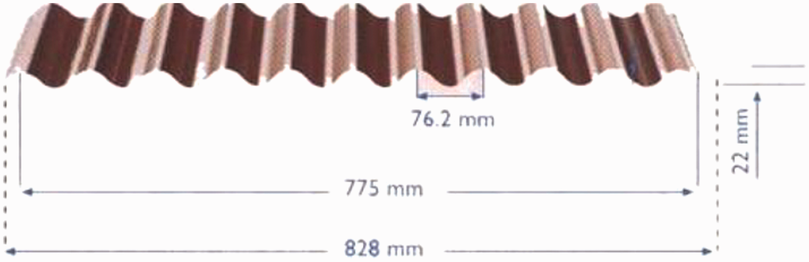
Corrugated plates, commonly called corrugated galvanized iron and abbreviated CGI, are building materials composed of sheets of hot-dipped galvanized mild steel, cold-rolled to produce a linear corrugated pattern in them. The corrugations increase the bending strength of the sheet in the direction perpendicular to the corrugations, but not parallel to them. Normally, each sheet is manufactured longer in its strong direction. Corrugated galvanized iron is lightweight and easily transported. It was and still is widely used, especially in rural and military buildings such as sheds and water tanks. In Figures 1 and 2, examples of trapezoidal and sinusoidal corrugated plates are shown with pitch and depth values.
Trapezoidal corrugated plate. Sinusoidal corrugated plate.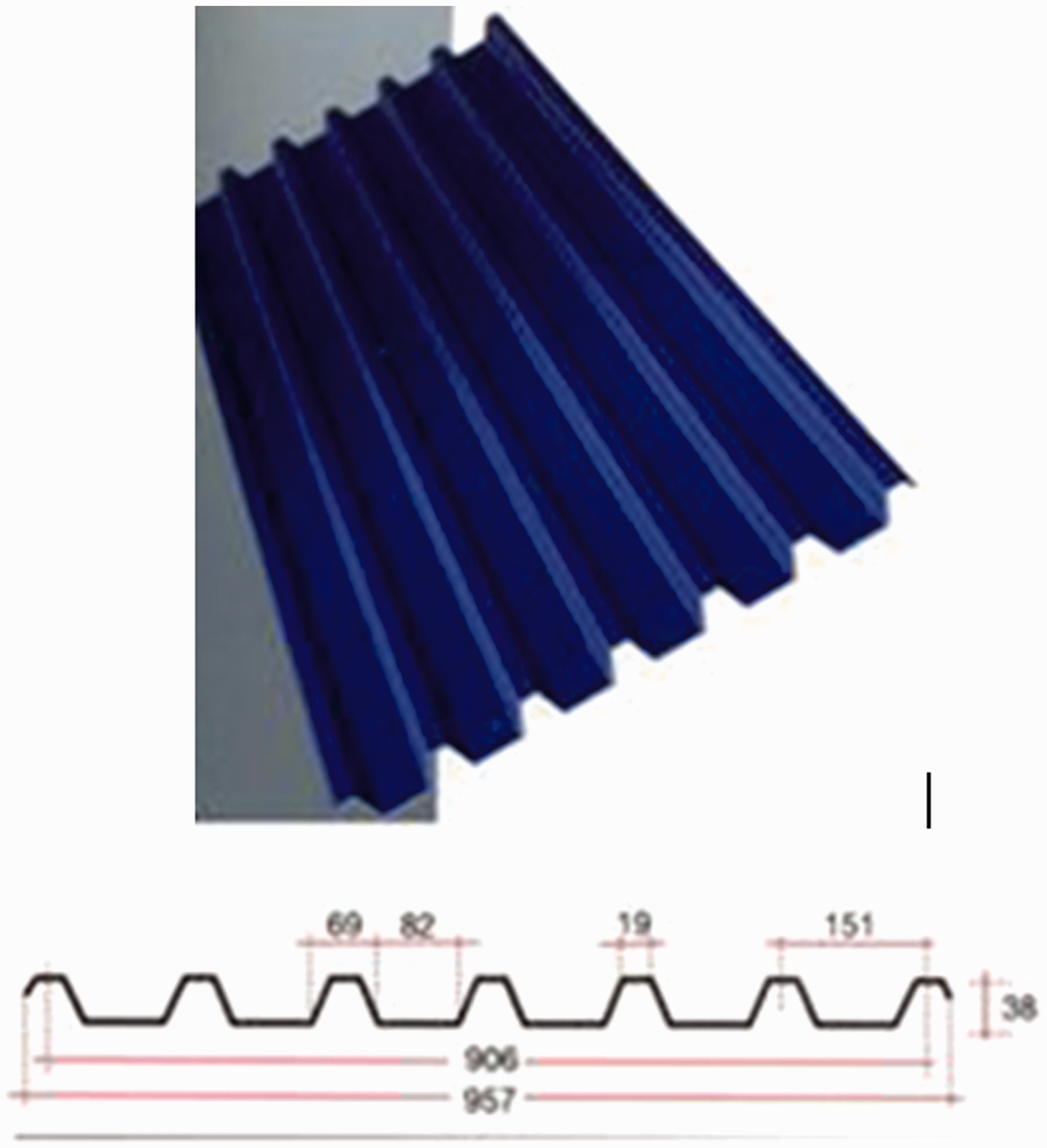
In 1995, Li investigated the large amplitude axisymmetrical free vibration of corrugated circular plates with free central holes and clamped at the outer edge in an analytical manner. In 2007, Peng et al. studied the elastic bending of unstiffened and stiffened corrugated plates and a mesh-free Galerkin method was presented for the analyses. The dynamic behavior of corrugated panels (with or without endplates) was studied by Liang et al. (2007), where both theoretical and finite element (FE) analyses were carried out, and comparisons between these two groups of results and further illustrations were also provided. The study of Liew et al. (2007) presents a geometrically nonlinear analysis of stiffened and unstiffened corrugated plates using a mesh-free Galerkin method that is based on the first-order shear deformation theory (FSDT). The strains are assumed to be small, and the corrugated plates are modeled approximately as equivalent orthotropic plates. The large deflection theory of von Karman is adopted in the nonlinear analysis of the orthotropic plate, and the equivalent flexure properties of the orthotropic plate are derived. In another study of Liew et al. (2009), a mesh-free Galerkin method for the free vibration analysis of unstiffened and stiffened corrugated plates was introduced, in which the corrugated plates were simulated with an equivalent orthotropic plate model. Yuan (2008) investigated the nonlinear free vibration and forced vibration of a corrugated shallow shell under concentrated load acting at the center based on the dynamic equations of nonlinear large deflection of axisymmetric shallow shells of revolution. The nonlinear partial differential equations of shallow shells were reduced to the nonlinear integral-differential equations using the method of Green’s function. To solve the integral-differential equations, the expansion method was used to obtain Green’s function. Wang et al. (2008) investigated the large amplitude-free vibration of corrugated circular plates with shallow sinusoidal corrugations under uniformly static temperature changes. The governing equations for corrugated plates are established from Hamilton’s principle based on the nonlinear bending theory of thin shallow shells. The study by Kazanci and Mecitoglu (2008) deals with the analysis and discussion of the nonlinear dynamic response of a laminated composite plate subjected to blast load. Dynamic equations of the plate are derived by the use of the virtual work principle. The geometric nonlinearity effects are taken into account with von Karman’s large deflection theory of thin plates. In 2004, Aboura et al. created a model which takes into account the geometrical and mechanical properties of the corrugated cardboard constituents. An experimental methodology was also proposed to obtain both the in-plane elastic properties of each constituent and the corrugated cardboard. Liu and Li (1989) investigated problems of practical and theoretical interests for the nonlinear bending and vibration of corrugated circular plates with plane central regions based on the nonlinear bending and vibration theories of anisotropic circular plates. Characteristic relations for uniformly loaded corrugated circular plates and a relation of the nonlinear period vs amplitude for free vibrational corrugated circular plates were obtained using Galerkin’s method. In another study by Liu (1984), the problem of large deflections for corrugated circular plates with a plane central region under the action of concentrated loads at the center were solved by means of the nonlinear bending theory for anisotropic circular plates. The characteristic relation of the plate was obtained using the modified iteration method. In 1999, a nonlinear geometric analysis of trapezoidal corrugated sheet was reported for the first time by Samanta and Mukhopadhyay. In addition to three-dimensional analysis, an equivalent orthotropic model was proposed in the study that includes both extensional and bending rigidities. The analysis was extended to the determination of the free vibration characteristics of the corrugated sheet. A comparison of the displacements and natural frequencies of folded plates is made to demonstrate the versatility of the proposed approach. In 2001, Wu and Yu presented a simple approach to reduce the governing equations for orthotropic corrugated core sandwich plates to a single equation containing only one displacement function and obtained the exact solution of the natural frequencies for rectangular corrugated-core sandwich plates with all edges simply supported. In 2003, Zietsman et al. considered the vibration of a thin rectangular plate supported by identical beams at two opposing sides. This plate-beam system was rigidly supported on the remaining sides. They used the finite element method to calculate the natural frequencies for the plate-beam system and to solve the associated equilibrium problem.
Our study is completely based on the natural frequency and mode shape analyses of corrugated galvanized plates with varying pitches and depths. The effect of the residual stresses and gradient thickness generated by the corrugation process were not taken into account because the plates were taken to be ideal.
The aim of the present study is to provide an extensive source about the vibration of corrugated plates, for design engineers, exhibiting numerous cases including various parameters like corrugation height, width and number.
2. Corrugated plate models
We first created the models for trapezoidally corrugated plates, abbreviated “TRP”. The technical drawing and section properties of the plate are given in Figure 3.
Properties of the TRP model.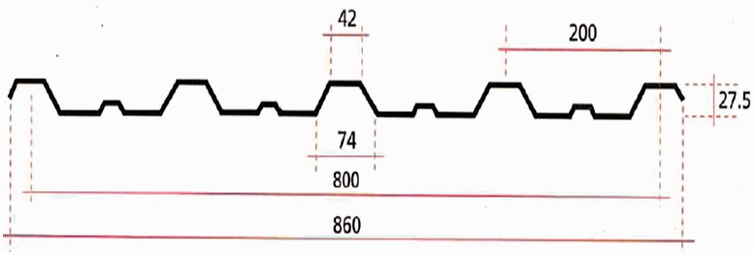
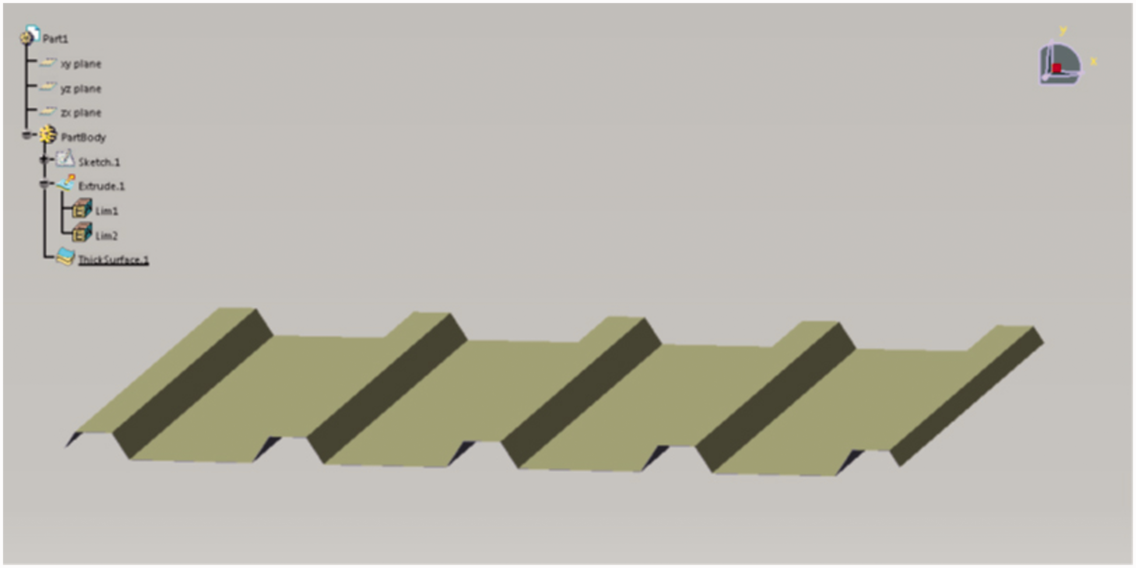
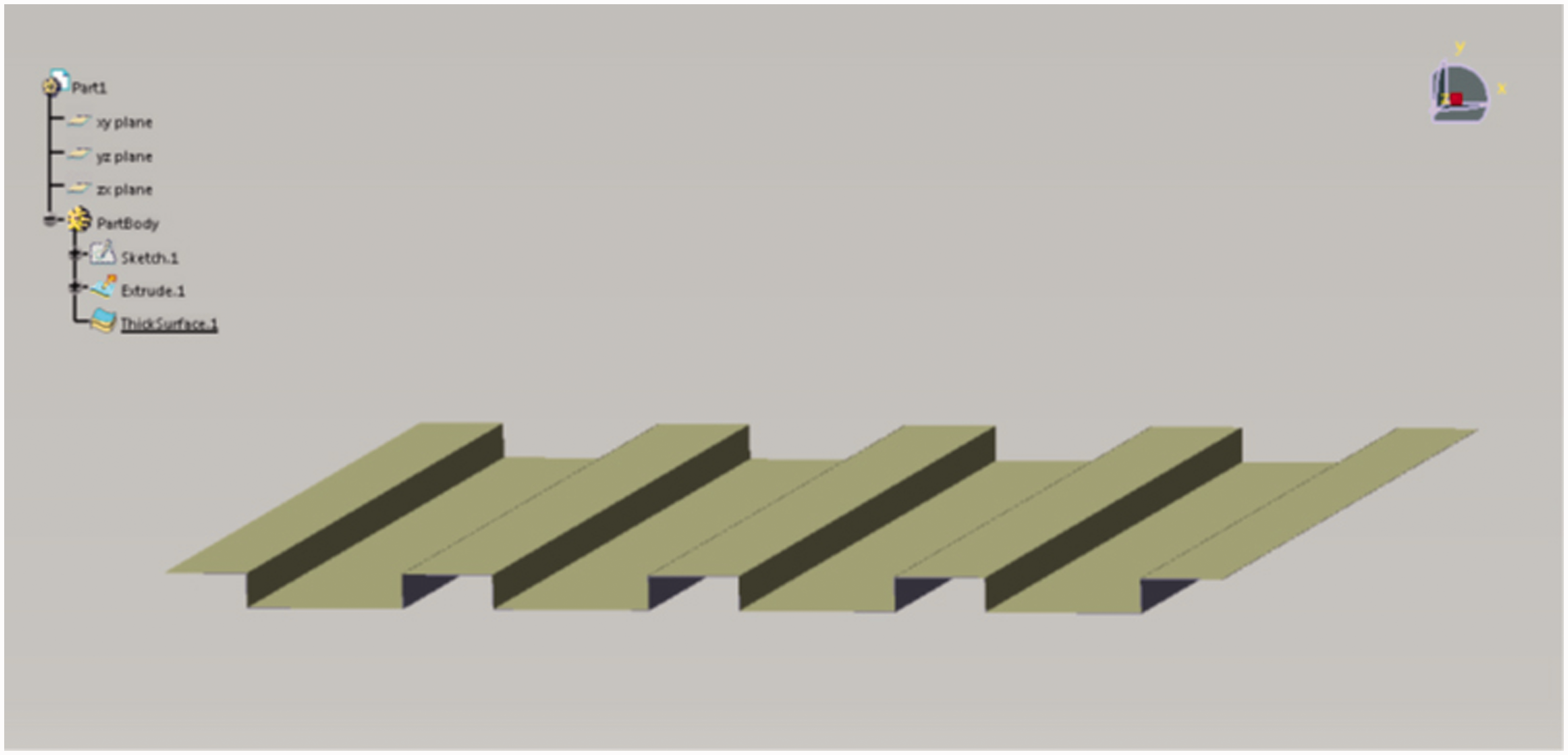
The parameters that are variable are the corrugation number and the corrugation height. The number of corrugations varies from 3 to 11, and the corrugation height varies from 20 mm to 30 mm. The thickness of the plate is 0.5 mm. The dimensions are 860 × 860 mm. These models, which were created in CATIA, were named using the “TRPXXhYY” format in which XX is the number of corrugations and YY shows the corrugation height. For example, “TRP08h21” is a trapezoidally corrugated plate with eight corrugations and a height of 21 mm. A solid model drawing of the plate is shown in Figure 4.
TRP model.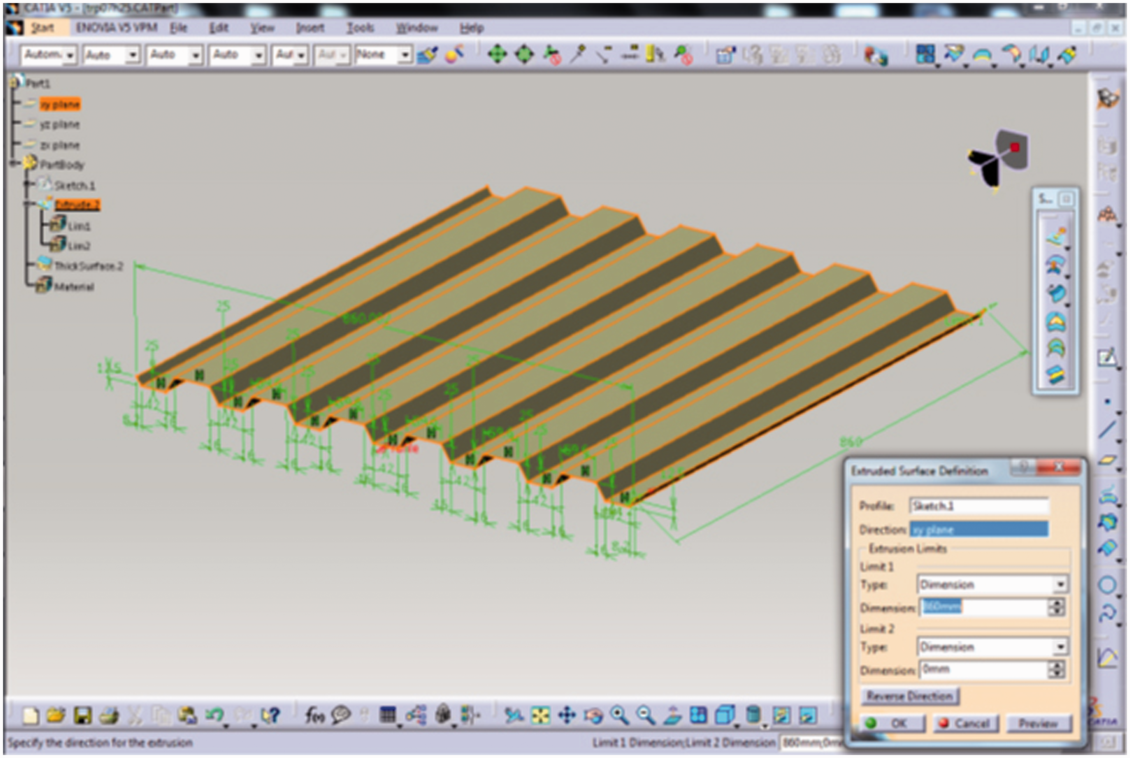
The other models created for the analyses are sinusoidally corrugated plates, abbreviated “SIN”. The technical drawing and section properties of the plate are given in Figure 5.
Properties of the SIN model.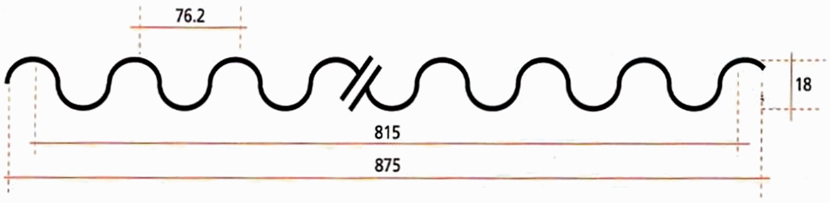
The parameters that are variable are the corrugation number and corrugation height, as in the trapezoidally corrugated plates. The number of corrugations varies from 10 to 20, and the corrugation height varies from 10 mm to 30 mm. The thickness of the plate is 0.4 mm. The dimensions are 875 × 875 mm. These models, which were also created in CATIA, were named using the “SINXXhYY” format in which XX is the number of corrugations and YY is the corrugation height. For example, “SIN12h28” is a sinusoidally corrugated plate with 12 corrugations and a height of 28 mm. A solid model drawing of the plate is shown in Figure 6.
SIN model.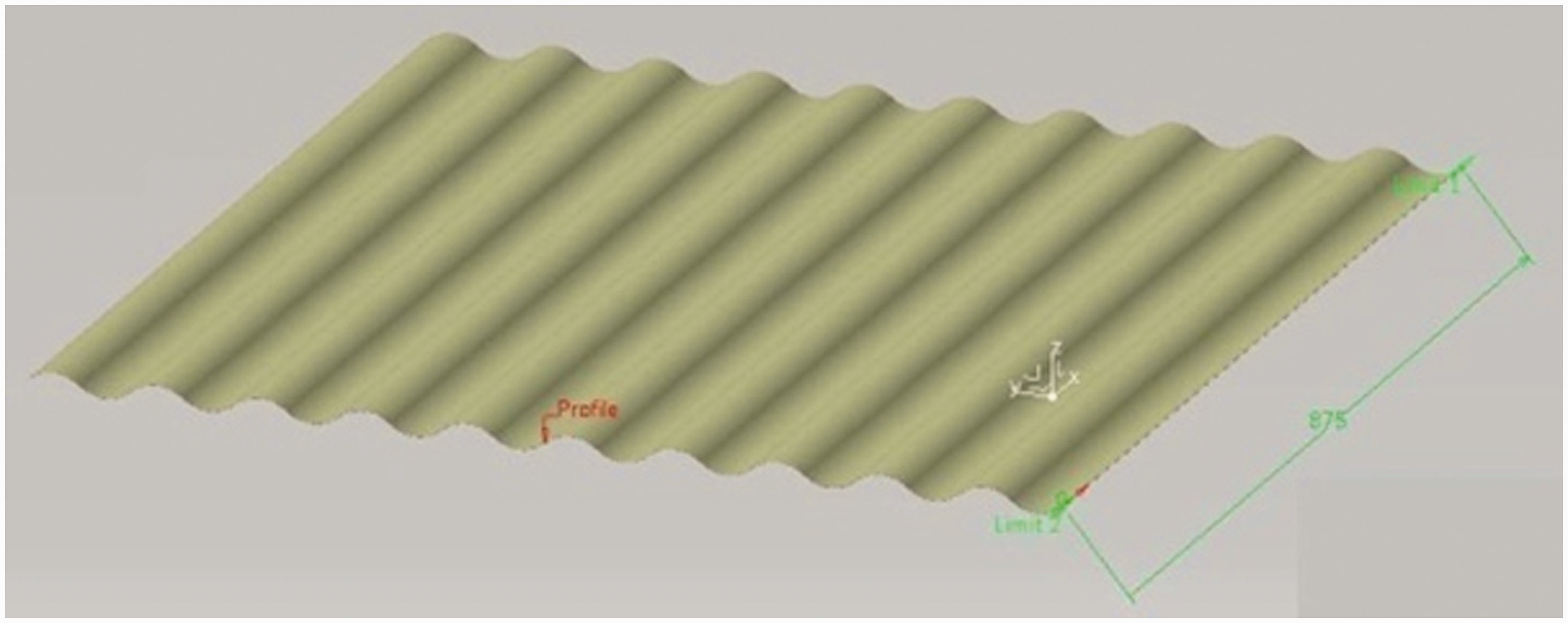
The last model type created for analyses is the “TRZ” model, which is a special type of trapezoidal corrugated plate. The section properties are the same as in Figure 4. All the dimensions are constant except the corrugation top width (which is 42 mm in the figure). The number of corrugations and corrugation height are also constant at 5 and 27.5 mm, respectively. The only varying parameter is the corrugation top width, which varies from 0 to 74 mm. When the corrugation top width is 0, the plate corrugation is triangular, and when the corrugation top width is 74, the plate corrugation is a rectangle. This model is labeled “TRZXX,” where XX is the corrugation top width. Various models are shown in Figures 7 to 9.
TRZ00 model. TRZ38 model. TRZ74 model.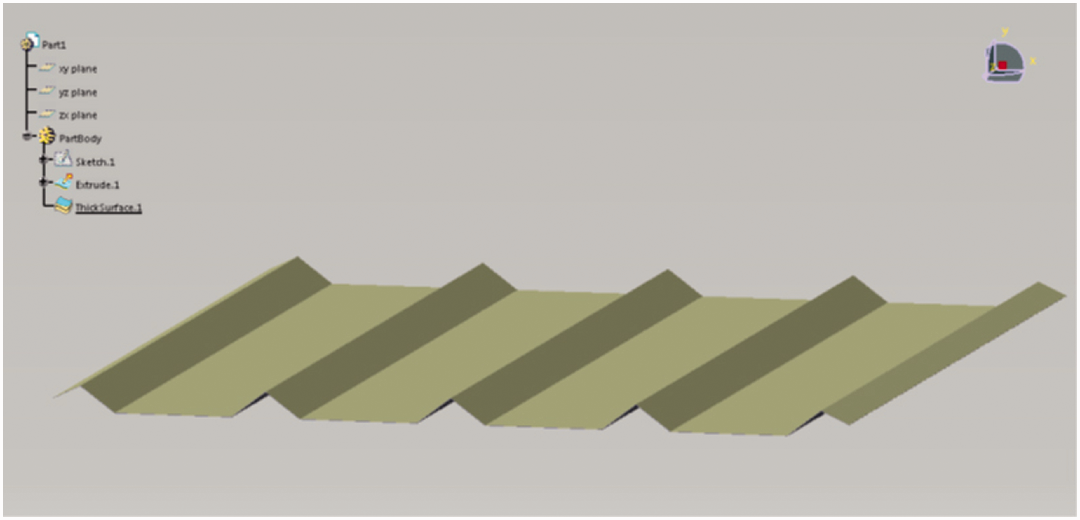
In the next section, these solid models created in CATIA were prepared for analyses in the ABAQUS software preprocessor environment.
3. Modal analyses
In the analyses, the parameters given below were used for the finite element modal analyses:
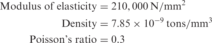
The analyses were conducted for a boundary condition with the four sides encastre. A sample preprocessor image for the finite element model of the “TRP05h28” model with boundary conditions is shown in Figure 10.
Finite element method model of TRP05H28.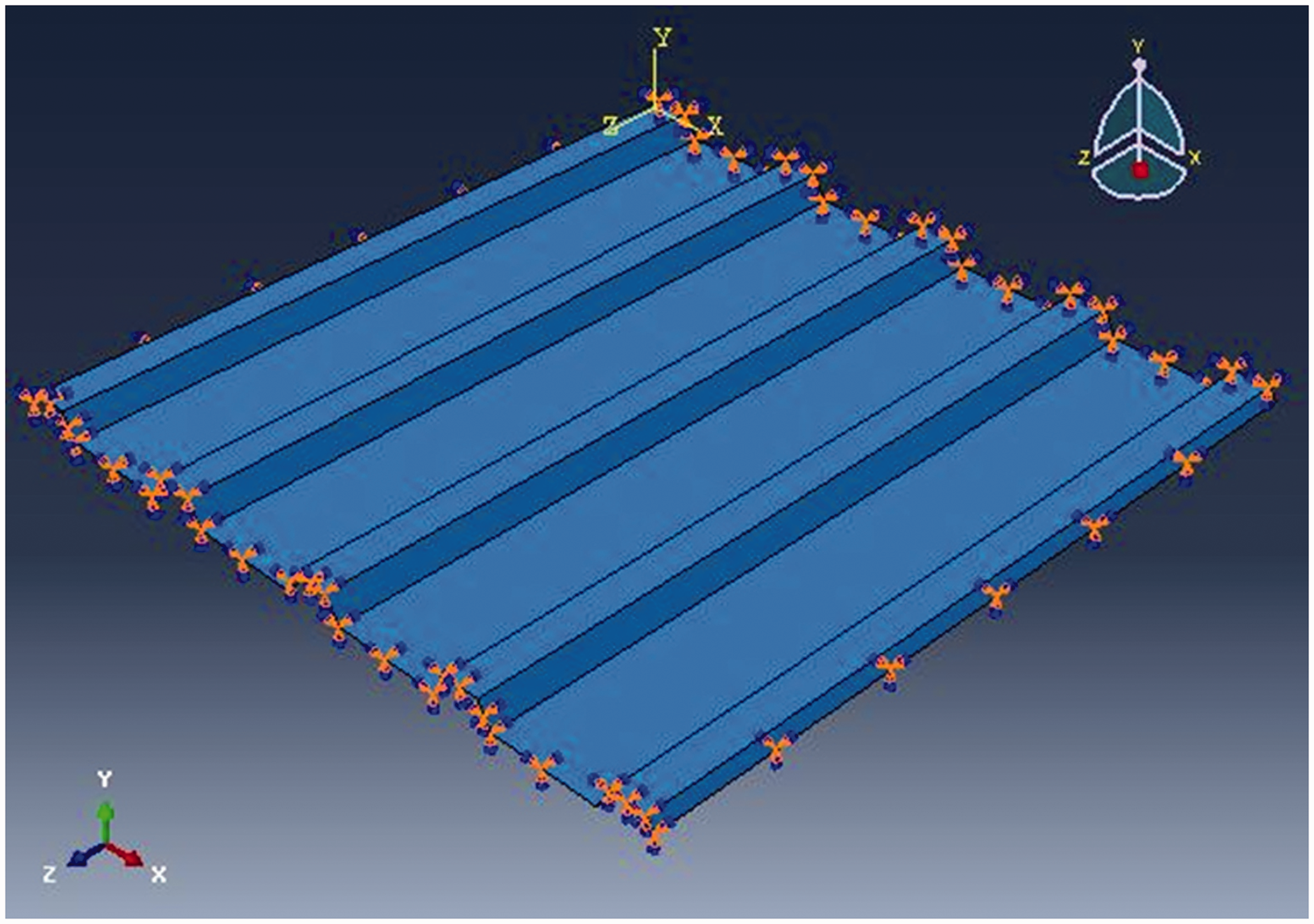
In the finite element analyses, the mesh size was 20 mm for trapezoidally corrugated plates and 4 mm for sinusoidally corrugated plates. In Figure 11, the mesh of the plate is shown.
Mesh of TRP05H28.
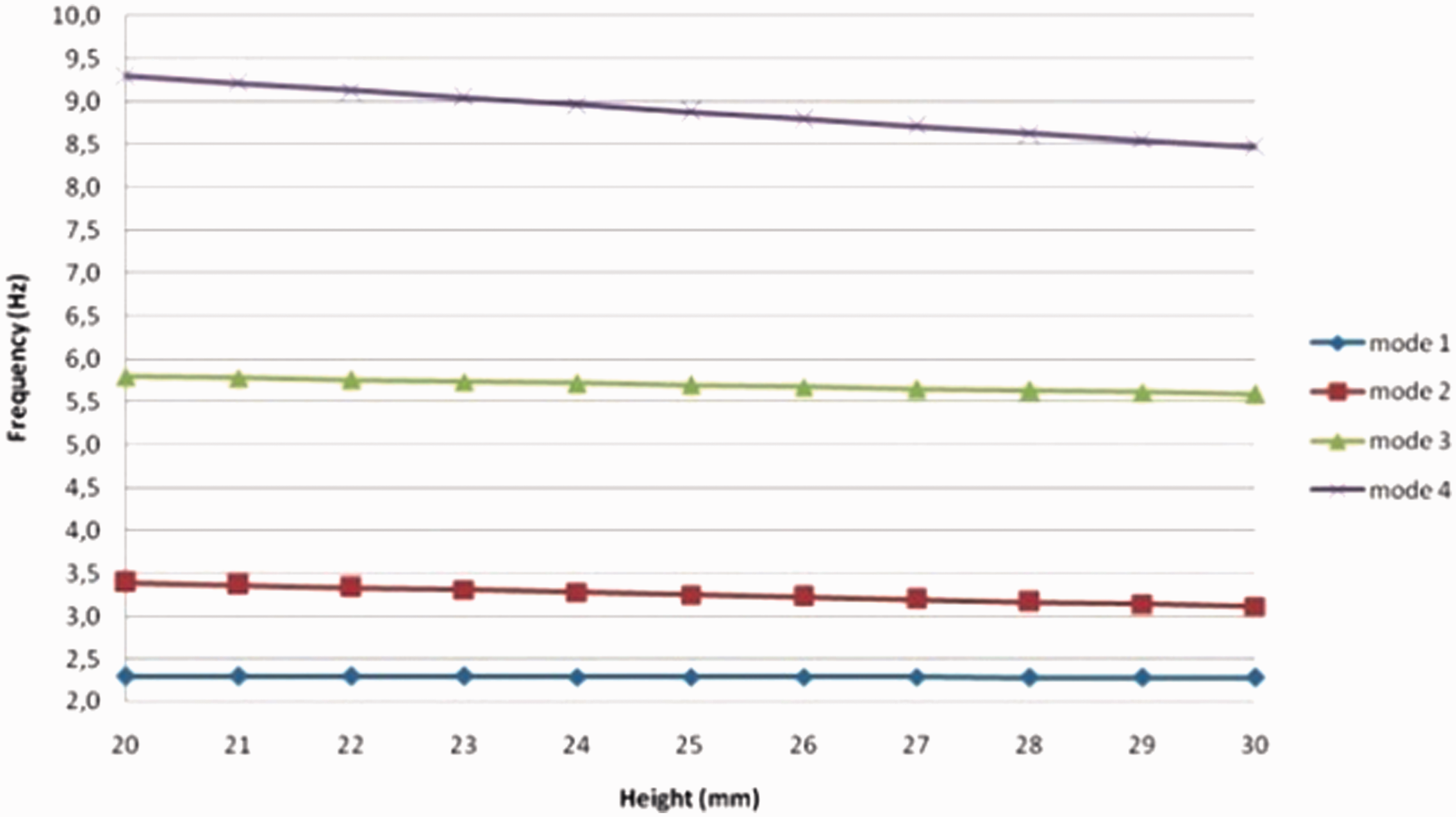
The technique given above was applied to 368 different corrugated plate models for two different boundary conditions: four sides encastre and four sides free. A total of 736 analyses were conducted. It is clear that, because of length, it is impossible to present all the natural frequencies of all models in a table. Instead, we show the change in the natural frequencies according to the height of the corrugated plate for a certain number of corrugations and the boundary condition. Figures 12 and 13 show the changes in the natural frequencies according to the height of the trapezoidally corrugated plate with five corrugations of four sides encastre and four sides free.
Natural frequency analysis for TRP05 with four sides encastre. Natural frequency analysis for TRP05 with four sides free.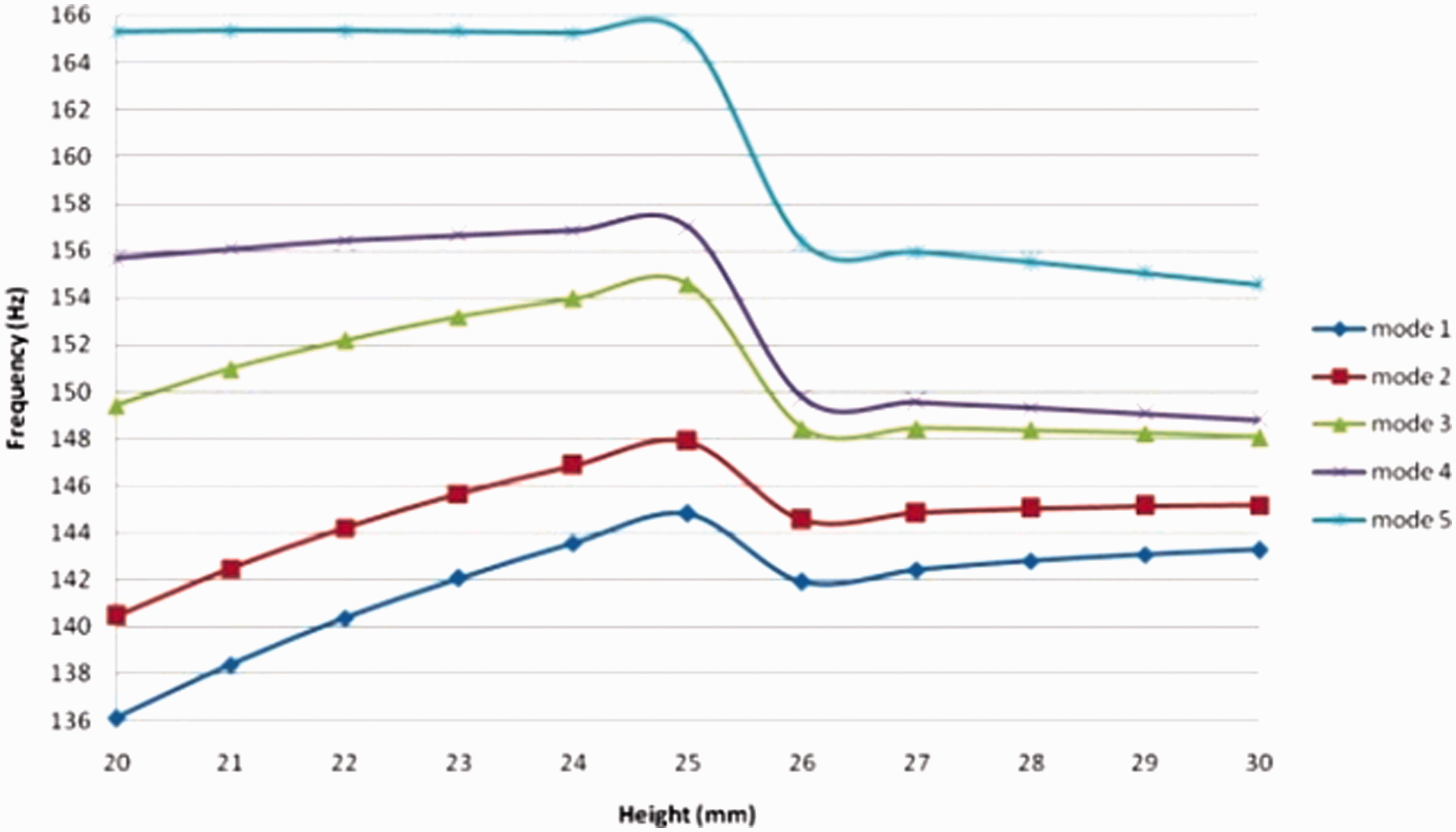
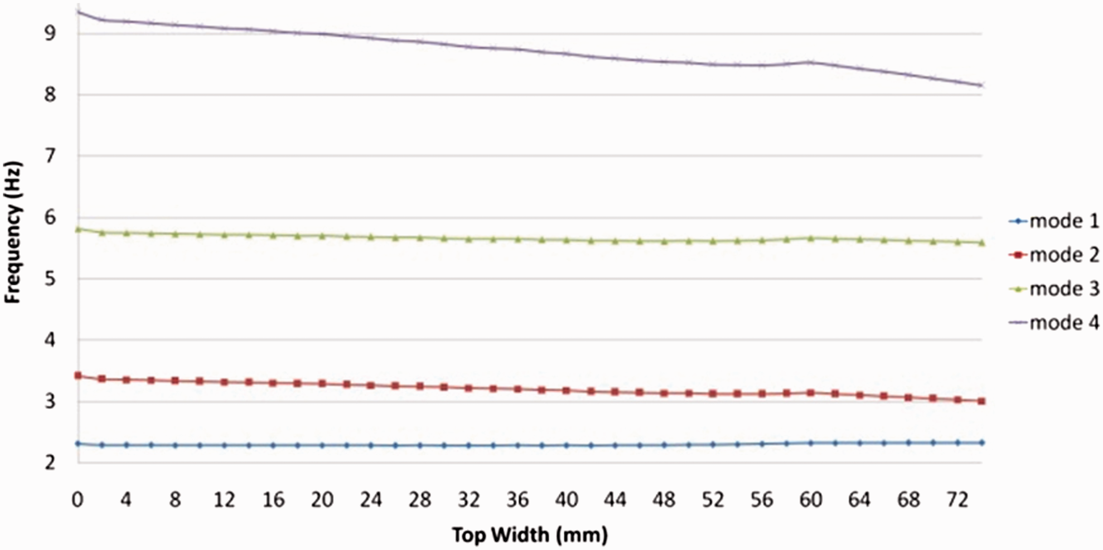
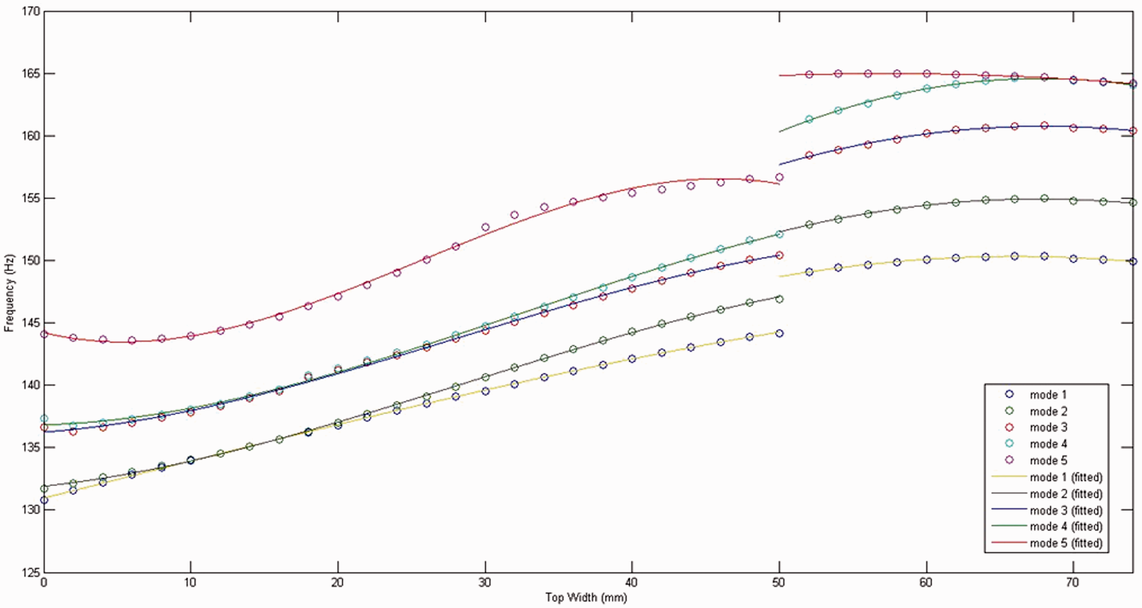
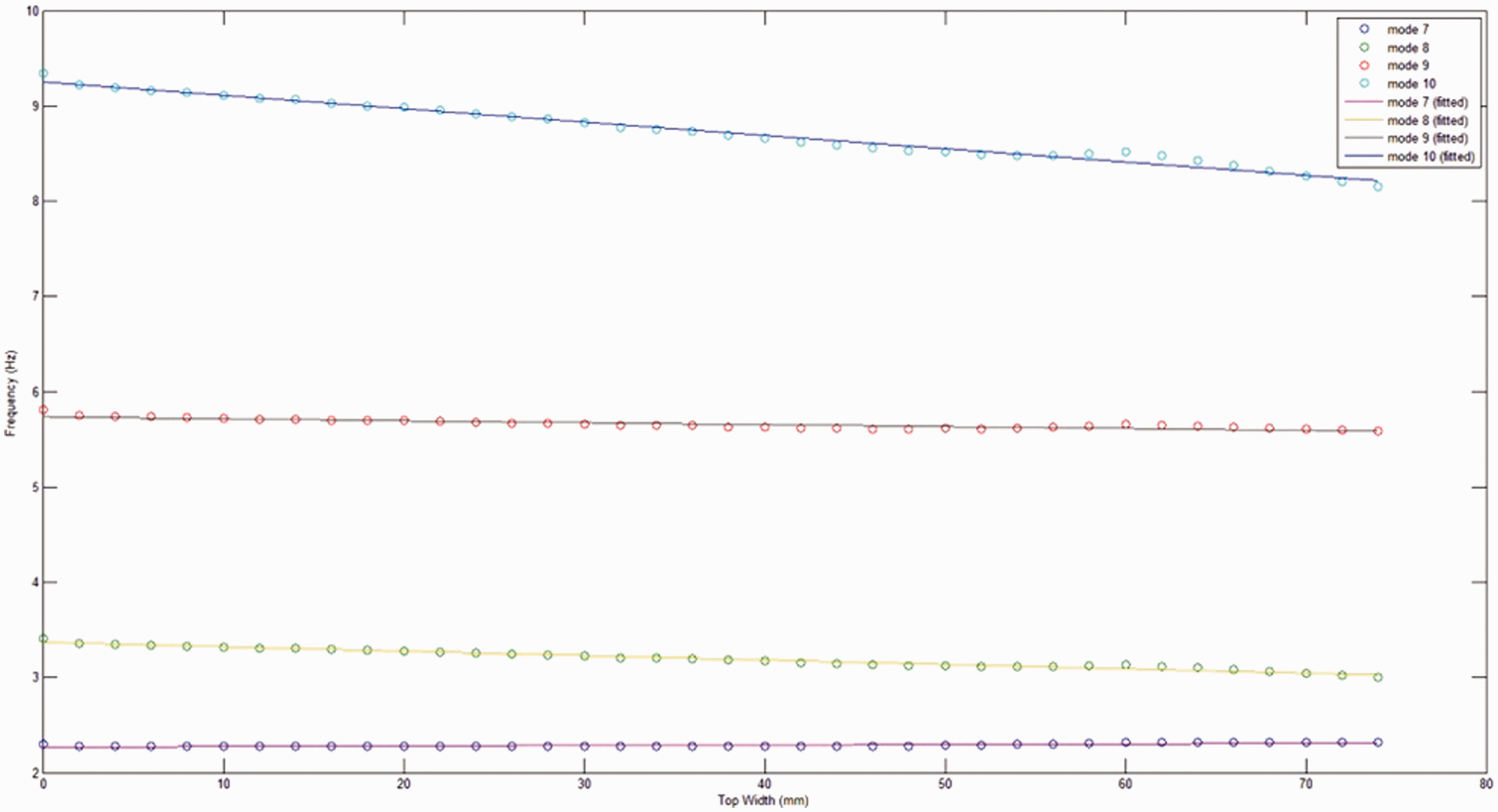
Figures 14 and 15 show the changes in frequency according to the corrugation top width for the special type of trapezoidally corrugated plates abbreviated with “TRZXX”.
Natural frequency analysis for TRZ with four sides encastre. Natural frequency analysis for TRZ with four sides free.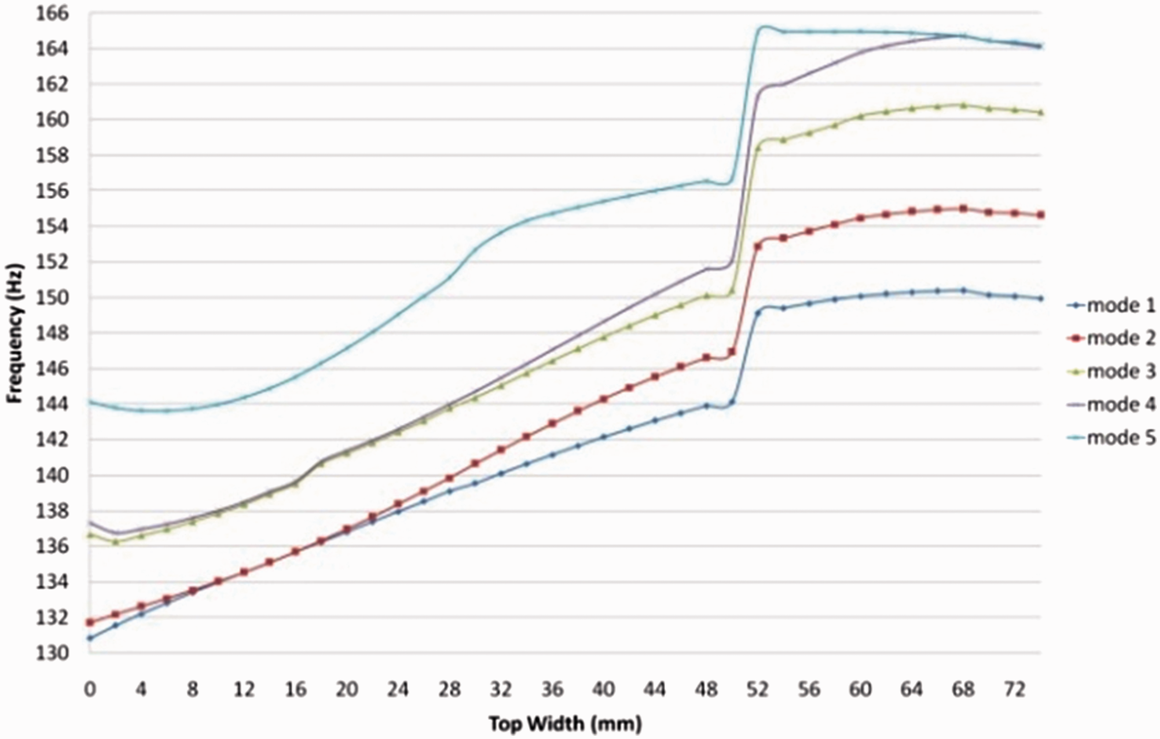
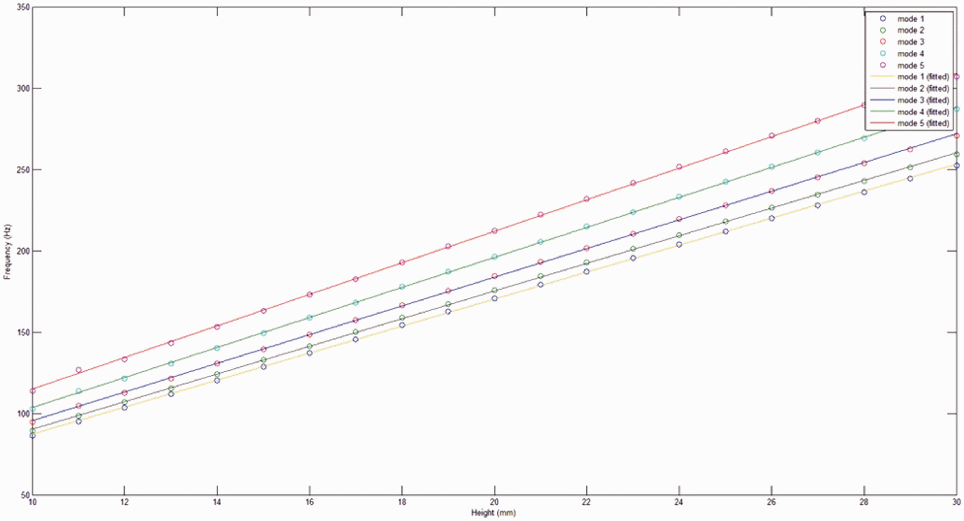
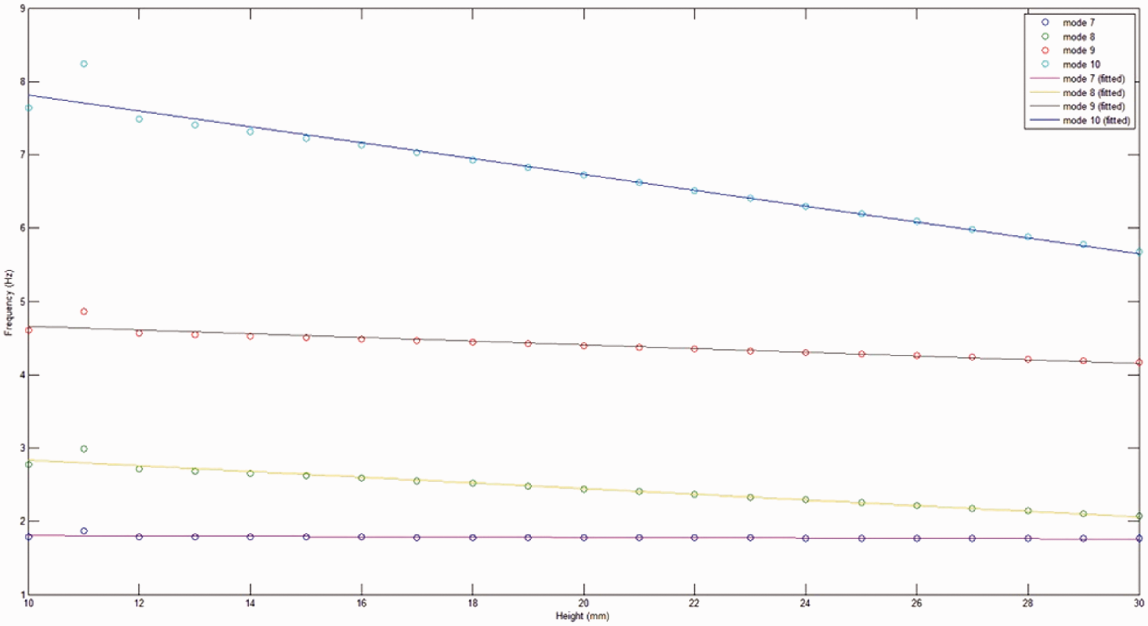
Figures 16 and 17 show the changes in the natural frequencies according to the height of the sinusoidally corrugated plate with 12 corrugations of four sides encastre and four sides free.
Natural frequency analysis for SIN12 with four sides encastre. Natural frequency analysis for SIN12 with four sides free.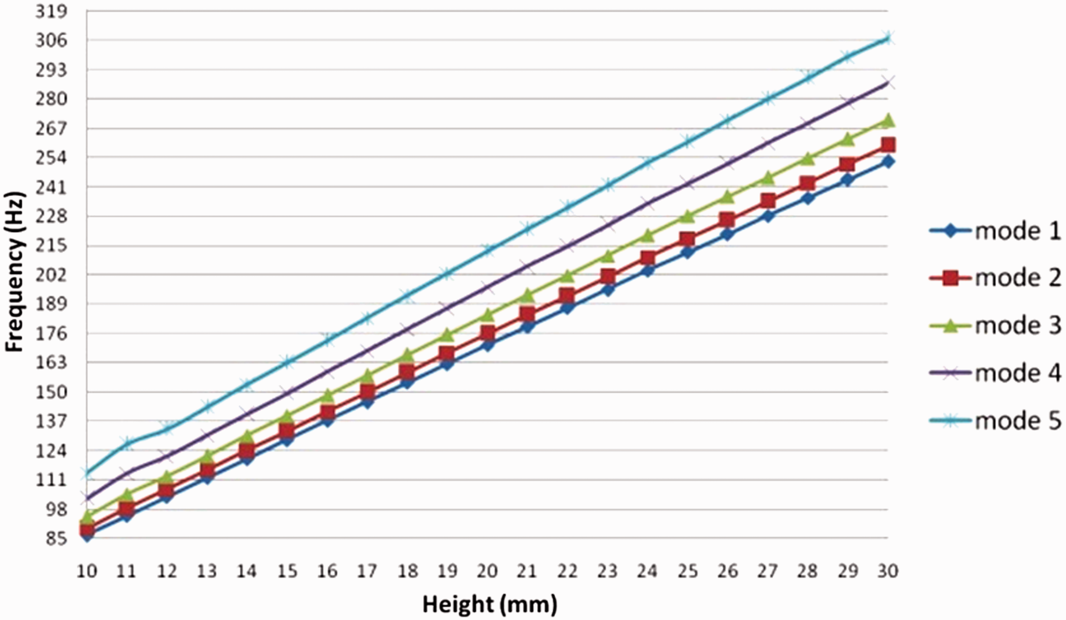
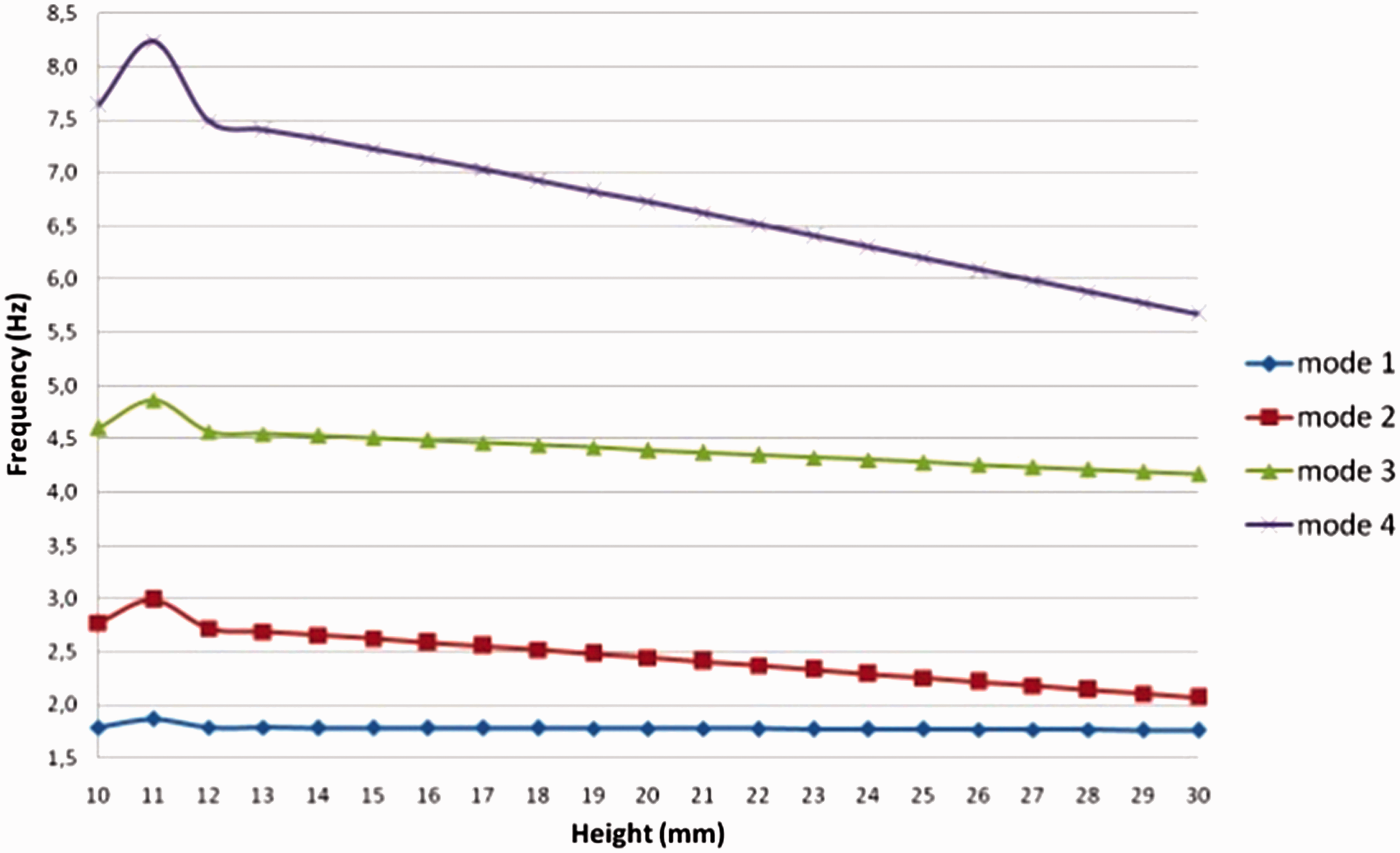
These figures, which show the changes in the natural frequencies according to the height of the corrugated plates for various numbers of corrugations and the two boundary conditions, were obtained using finite element modal analyses.
For clamped plates, Figure 12 shows that the natural frequency increases to a critical height in lower modes and then remains approximately constant. In higher modes it is nearly constant, being of different values before and after the critical value.
Figure 13 shows that the natural frequencies decrease very slightly versus increasing values of corrugation heights for the plates with four edges free.
For clamped plates, Figure 14 indicates that natural frequencies increase as the corrugation profile approaches a square in all modes before a critical value of top width and after that it slightly affects the frequencies.
Figure 15 shows that the top width has a very slight effect on the natural frequencies of free plates.
Figure 16 and Figure 17 depict an approximately linear increase and decrease versus increasing values of corrugation heights respectively, for sinusoidal corrugated plates, with the exception of a local small jump in Figure 17.
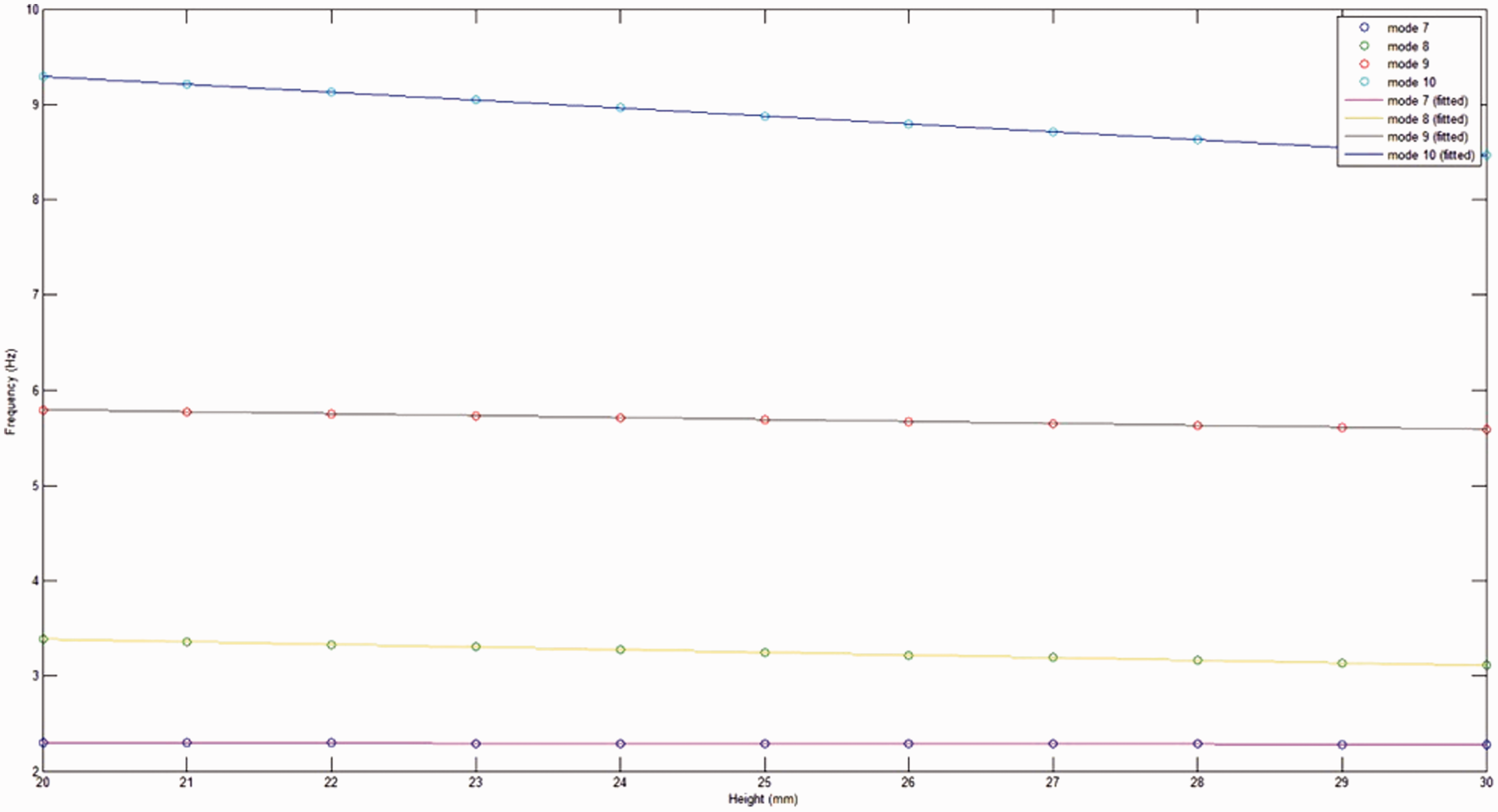
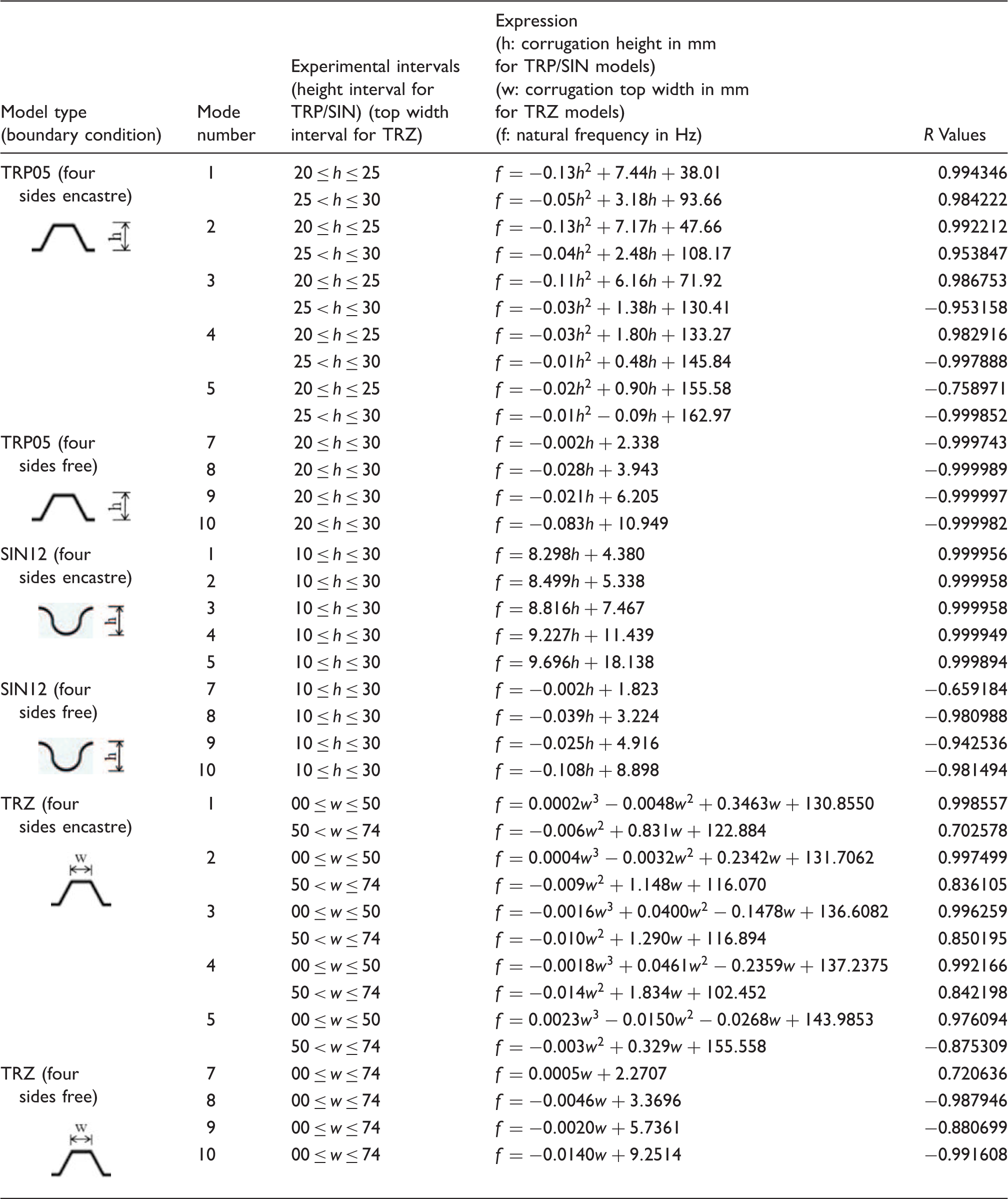
Figures 18–23 and Table 1 show the regressions performed on the results of the finite element analyses. The discontinuities in Figures 18 and 20 refer to the sudden jumps on the original figures of analyses (Figures 12 and 14). Since the curves in these figures show different characteristics and make sudden jumps before and after a critical value, we had to divide the figures into two sections, which is why we have the discontinuities in Figures 18 and 20 on the critical value of corrugation height and width.
Natural frequency regression for TRP05 with four sides encastre. Natural frequency regression for TRP05 with four sides free. Natural frequency regression for TRZ with four sides encastre. Natural frequency regression for TRZ with four sides free. Natural frequency regression for SIN12 with four sides encastre. Natural frequency regression for SIN12 with four sides free. Natural frequencies regression expressions.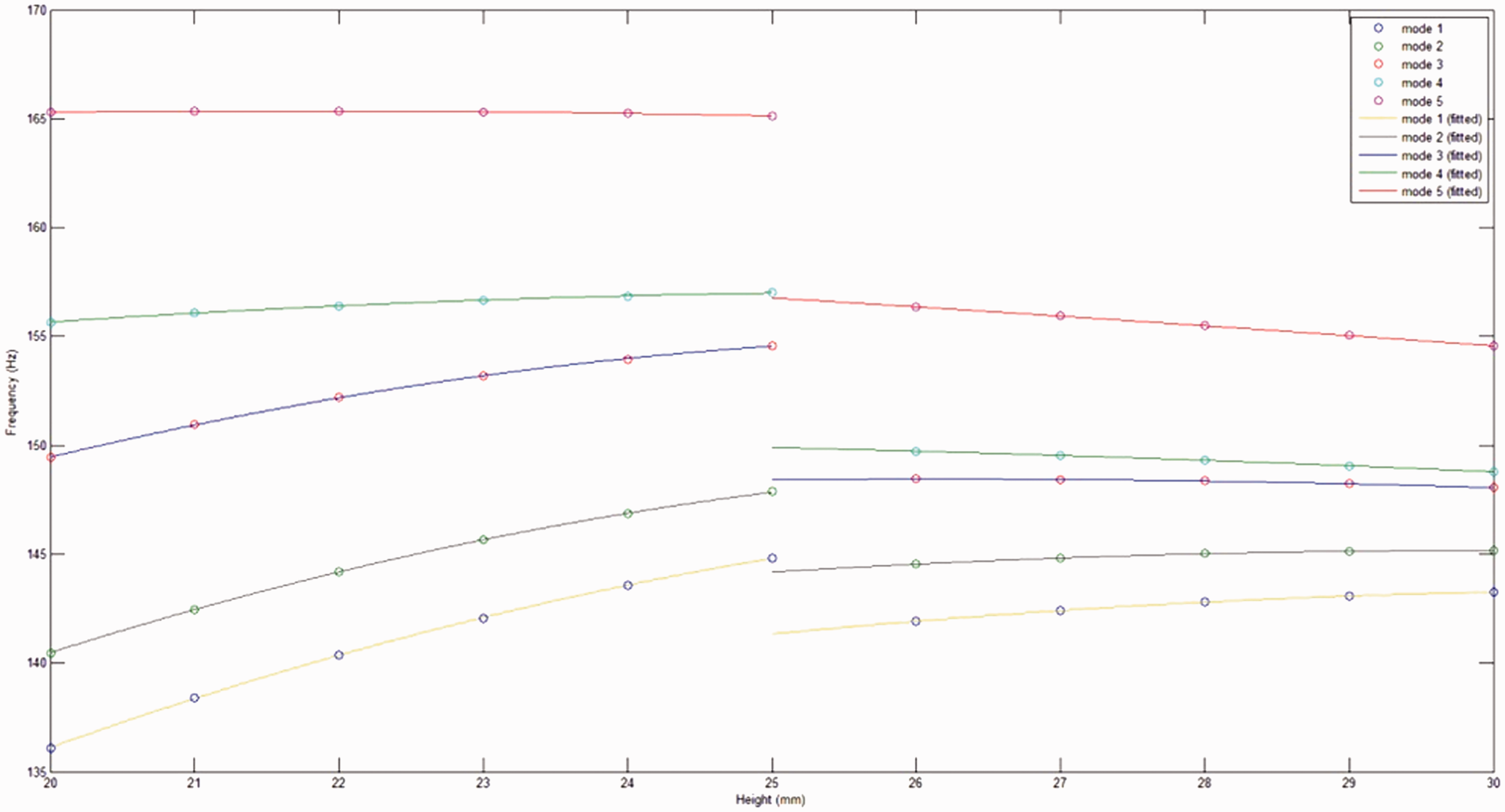
As well as the analyses according to the height and top width, Figures 24–27 show the changes in the natural frequencies according to the number of corrugations for certain values of height for the two boundary conditions. Height has been taken constant as 10 mm for SIN models and 20 mm for TRP models in analyses.
Changes in frequencies for SIN with four sides encastre according to the number of corrugations. Changes in frequencies for SIN with four sides free according to the number of corrugations. Changes in frequencies for TRP with four sides encastre according to the number of corrugations. Changes in frequencies for TRP with four sides free according to the number of corrugations.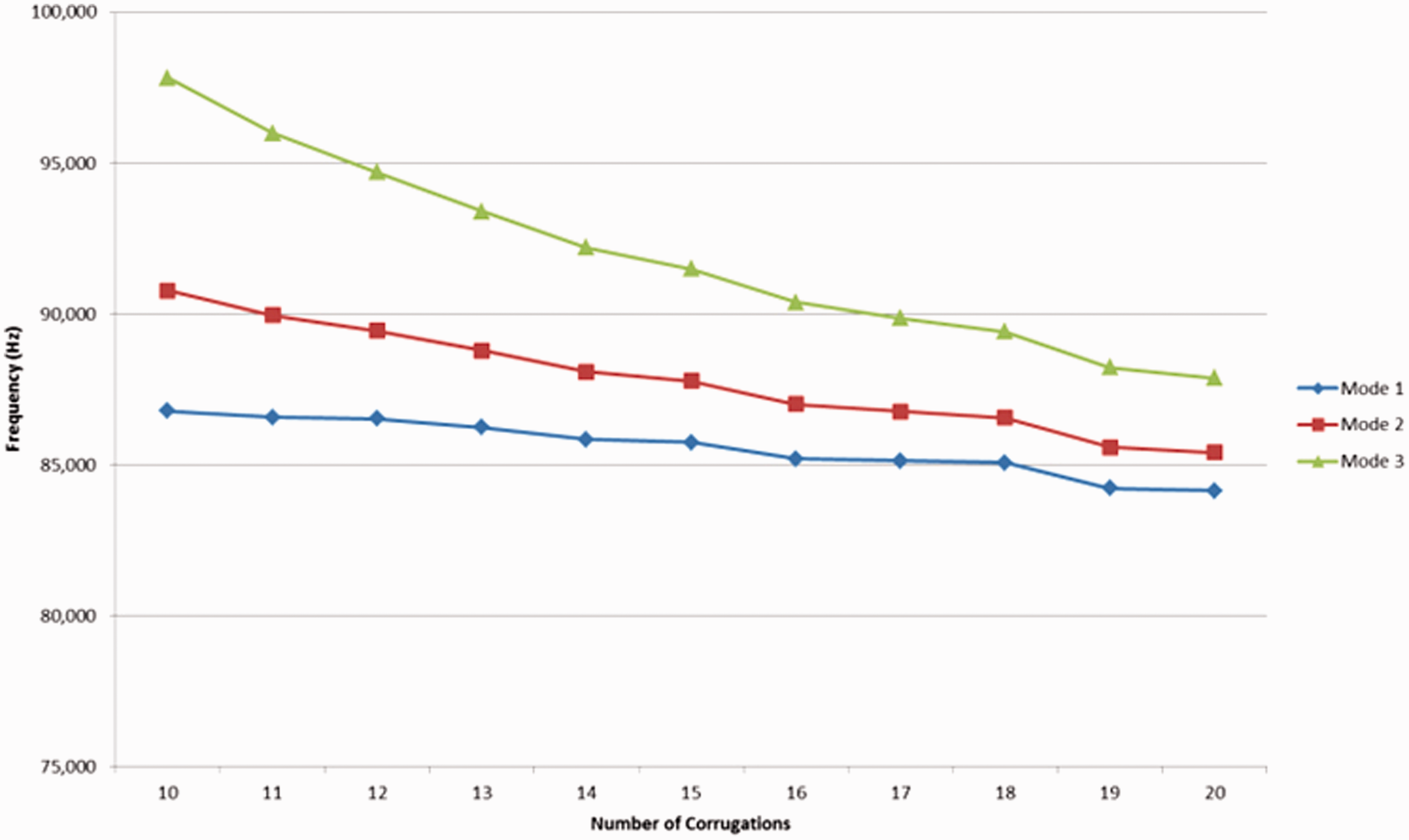
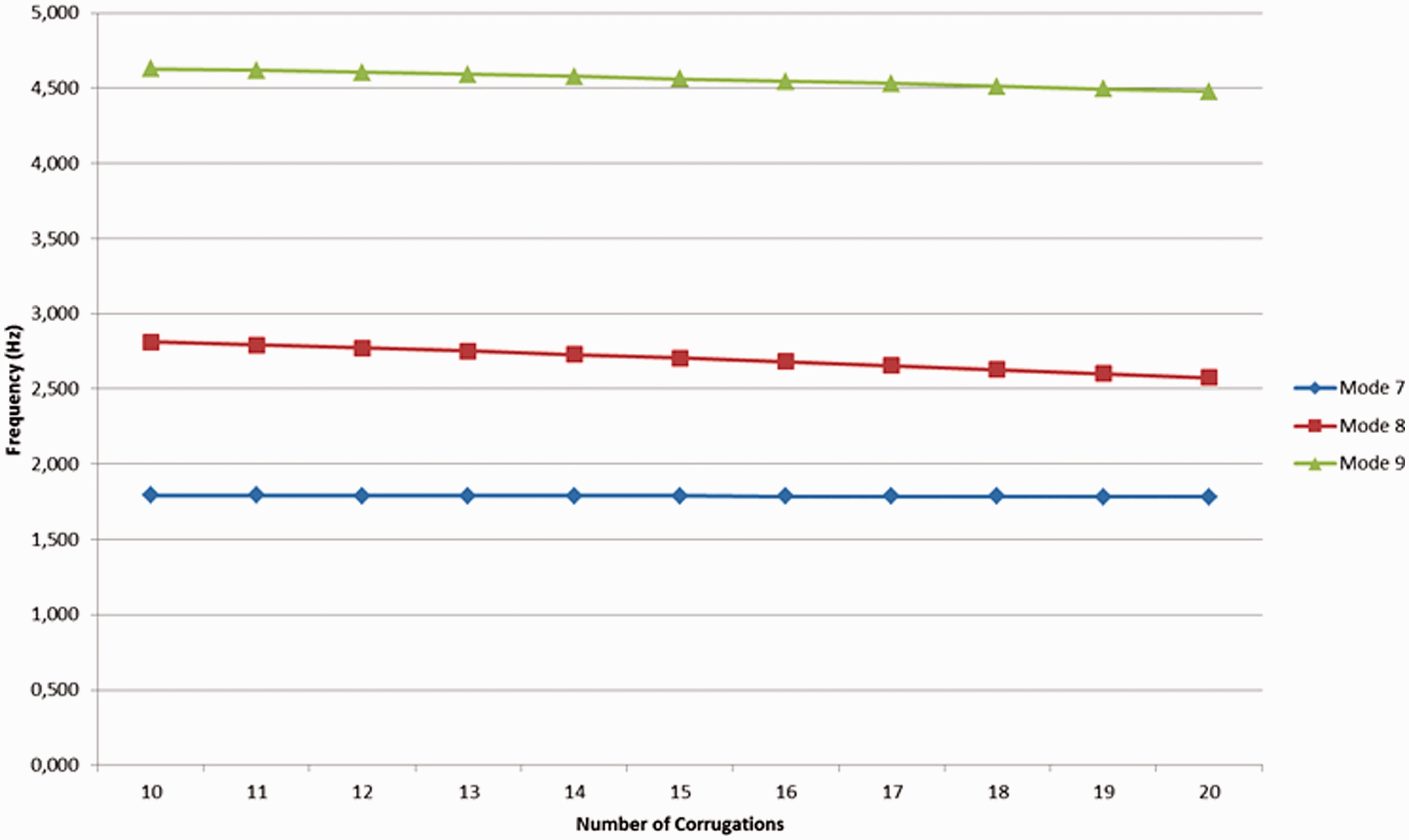
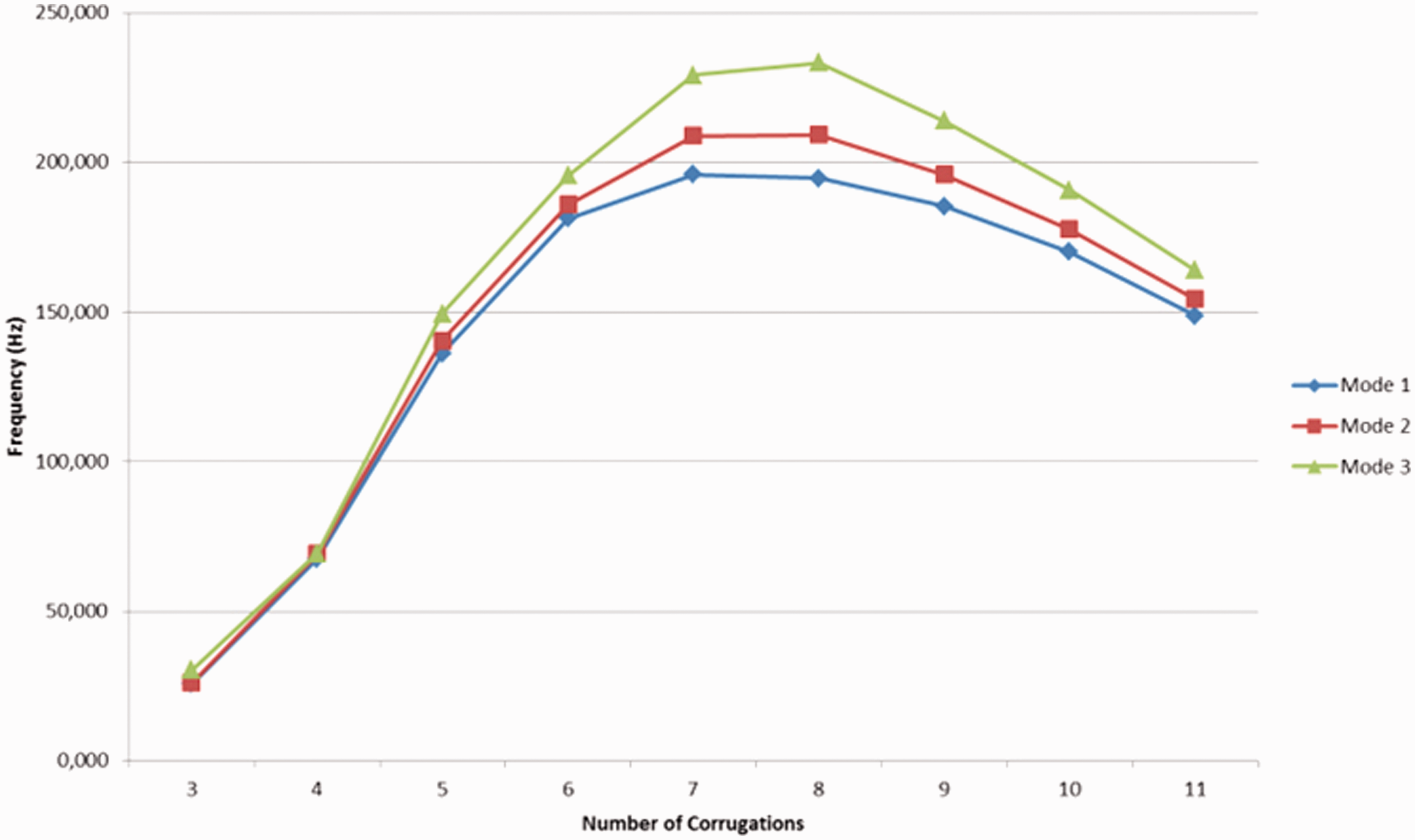
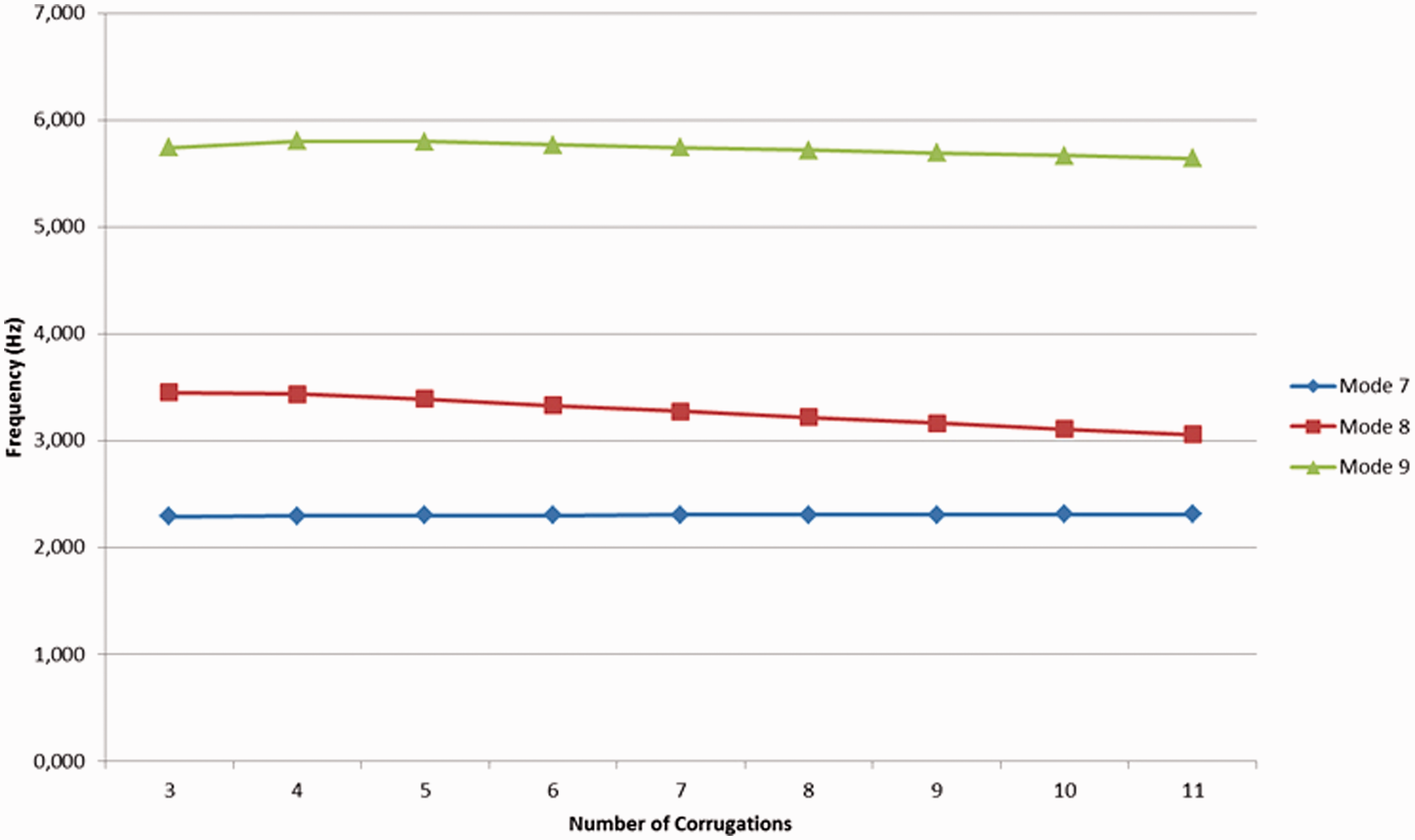
Figures 24 to 27 exhibit the effect of corrugation number on the natural frequencies. For clamped plates, it is observed that the corrugation number has a considerable effect on the natural frequencies, whereas it is negligible for free plates.
Using the analyses, we also obtained all the mode shapes of the corrugated models. Figure 28 shows the 9. mode shape of the “SIN12h18” model with four sides free.
SIN12H18 mode shape.
4. Experimental modal analyses
The corrugated plate models that were analyzed using the finite element method were also investigated experimentally using an experimental analysis technique. Naturally, it is impossible to obtain all models on the market. We selected “SIN12h18” as the representative sinusoidally corrugated plate and “TRP05h27” as the representative trapezoidally corrugated plate for the experiments. The thickness of the “SIN12h18” plate is 0.4 mm and the dimensions are 875 × 875 mm where the thickness of the “TRP05h27” plate is 0.5 mm and the dimensions are 860 × 860 mm.
The roving hammer impact test method was selected as the experimental modal analysis technique. This means that the accelerometer was fixed to a point over the mesh, and the impact hammer was applied to each mesh point on the plate. The impact forces from the hammer and the responses from the sensor were collected by a two-channel data recorder and analyzer (Brüel and Kjær’s PULSE LAN-XI Data Acquisition Platform). Then, using these data, the frequency response functions (FRF) were obtained. Using modal analysis software (Brüel and Kjær’s PULSE Reflex Modal Analysis and PULSE Modal Test Consultant Software) and FRFs obtained from the recorder, we calculated the natural frequencies and mode shapes of the plates. The boundary condition for both plates was four sides free. The sinusoidal and trapezoidal plates used for the experiment are shown in Figure 29.
Plates used in the experiment.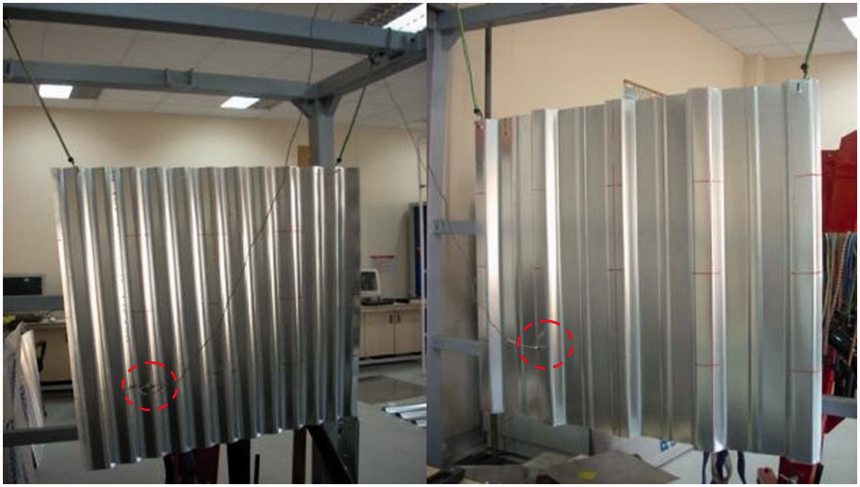
An impact hammer (B&K 8206) with a sensitivity of 22.7 mV/N was used for excitation, and an accelerometer (B&K 4507B) with a sensitivity of 100 mV/g was used to collect the responses. A mesh of 25 points was created on each plate, and the sensor was positioned on point #17. In Figure 30, the mesh and the roving hammer used during the experiment can be seen.
The mesh of the sinusoidally corrugated plate.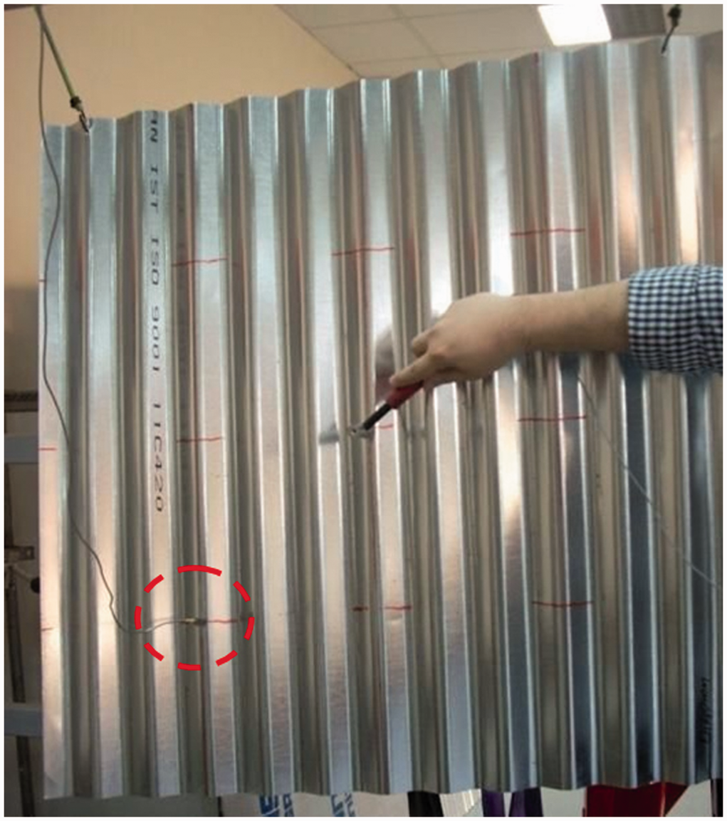
The mode shapes can be seen in Figures 31 and 32.
The mode shapes of SIN12H18. The mode shapes of TRP05H27.

5. Comparison of modal analyses
A comparison of the natural frequencies obtained using the finite element method and experimental modal analyses is given in Table 2 and Figure 33. The discrepancy in the table can be stated as
Comparison of experimental and numerical results. Comparison of the natural frequencies.
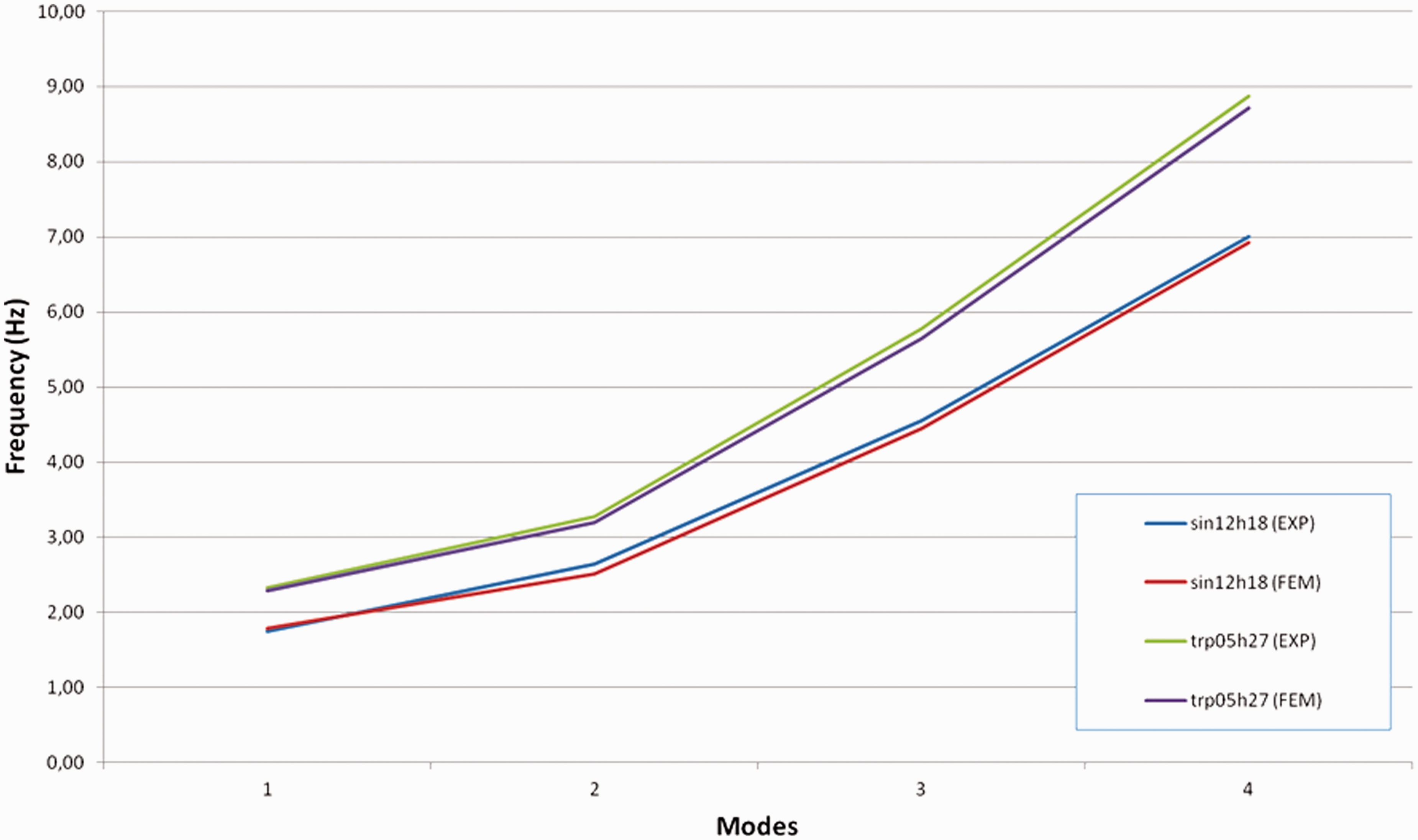
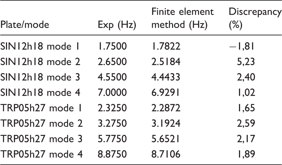
As shown in Table 2, the discrepancy between the experimental and numerical results do not exceed 6%. This discrepancy can be attributed to the fact that the theoretical boundary conditions for a completely free plate have been realized only in practical sense. In the experiments, we could not achieve exact boundary conditions because of the elastic rubbers used to hang the plates.
6. Conclusion
Figures 13 and 17, which display the changes in the natural frequencies of trapezoidally and sinusoidally corrugated plates with four sides free according to corrugation height, show that the corrugation height has almost no effect on the natural frequencies for lower modes. In higher modes, the change is approximately linear. Figures 12 and 16, which display the changes in the natural frequencies of trapezoidally and sinusoidally corrugated plates with four sides encastre, show that the change in the natural frequency according to the corrugation height is approximately linear before and after a critical value. Especially in Figure 12 and Figure 14, the natural frequency increases linearly until a critical height is reached, and then remains approximately constant after a sudden jump. In higher modes it is nearly constant, being of different values before and after the critical value.
Examination of Figures 12 and 14 indicates that a critical height exists for a constant width and a critical width exists for a constant height. In the authors’ opinion, this situation refers to a problem of stability. Since the clamped edges completely restrict the in-plane deformation, the corrugated plates undergo a different equilibrium condition as a critical geometry parameter is reached.
Figures 14 and 15 show the change in frequencies according to the corrugation top width for the special type of trapezoidally corrugated plates abbreviated with “TRZ”. For the models with four sides free, the behavior is much like standard trapezoidal plates. This means that the corrugation top width has a minimal effect on the natural frequency for TRZ models with four sides free. For the four sides encastre models, the change appears to be approximately linear in lower modes until a sudden jump at a critical value of width and then appears to stay constant.
In the authors’ opinion, for CCCC (four sides encastre), in-plane forces are produced and increased with increasing values of corrugation heights and this raises the plate rigidity and consequently natural frequencies. But as for FFFF (four sides free) plates, no in-plane forces are produced because of the missing restrictions. Moreover, a decrease in flexural rigidity can be expected during vibration especially in higher modes due to in-plane expansion. This decrease of rigidity causes slightly low natural frequencies as shown in Figures 16 and 17.
In all corrugated models with four sides free, the change in corrugation height and corrugation top width has little to no effect on the natural frequencies in the first modes. However, in corrugated models with four sides encastre, the change in natural frequencies according to corrugation height and corrugation width appears to be almost linear until a critical value is reached.
As a result, in this study, the dynamic behavior of trapezoidal and sinusoidal corrugated plates with varying corrugation height, width and number-of-corrugations has been analyzed experimentally and numerically. In total, 736 different analyses with varying parameters were conducted for two types of boundary conditions, which are four sides free and four sides encastre. The theoretical results were verified using the experimental modal analysis technique for some selected models that are being manufactured in the market, and it was found that the discrepancies between the experimental and numerical results do not exceed 6%. We believe that this study will be an extensive source of information about the vibration of corrugated plates, for design engineers and for optimization problems, exhibiting numerous cases including various parameters such as corrugation height, width and number.
Footnotes
Acknowledgements
We thank Askin Demir for her support in the preparation of solid models and analyses files.
Funding
This research received no specific grant from any funding agency in the public, commercial, or not-for-profit sectors.