






Abstract
In this study, a robust adaptive control method is employed for an active engine mount in a six-degree-of-freedom model of the engine on the mounts to improve vibration behavior of the engine. The vibration isolation performance and robustness of the employed robust adaptive controller are compared with a robust and an adaptive control technique. In addition, effectiveness of the robust adaptive control is evaluated in transient conditions (accelerating and gear change conditions). In this regard, a dynamic model for the engine supported by rubber and active mounts and its governing equations are presented. Then, a robust adaptive control, namely the robust Model Reference Adaptive Control (robust MRAC) technique, based on the gradient method with σ-modification, is designed by selecting a proper reference model. Moreover, a robust control, namely the H∞ control scheme and an adaptive control, namely MRAC, are employed for the active mount. Simulation results show that the robust MRAC has a better control performance (in reducing the transmitted force to the chassis) as compared with the H∞ scheme. In addition, in the face of large uncertainties, MRAC may diverge and become unstable. However, the robust MRAC is robust in the presence of large uncertainties. Also, robust MRAC is effective not only in constant engine speeds, but also in transient conditions.
Keywords
1. Introduction
Engine mounts have an important role in reducing undesired vibrations transmitted to the engine from road inputs and the engine at idle. Moreover, they are required to isolate the chassis from engine vibrations resulting from the inertia effects and combustion forces. To reduce engine vibrations due to the road inputs and idling, engine mounts should have high stiffness and high damping. On the other hand, low stiffness and low damping properties for the mounts are required to isolate the chassis from engine vibrations. The mentioned conflicting characteristics for a proper mount motivated the researchers to develop various types of engine mounts. Recently, semi-active and active engine mounts have been developed to improve vibration performance of the conventional rubber and hydraulic mounts.
Semi-active engine mounts have been developed with electrorheological fluids (Choi et al., 1999), magnetorheological fluids (Arzanpour and Golnaraghi, 2008), engine intake manifold vacuum (Kim and Singh, 1995) and so on. Moreover, active engine mounts with piezoelectric actuators (Shibayama et al., 1995) and electromagnetic actuators (Nakaji et al., 1999) have been investigated by some researchers. Recently, some automotive manufacturers have performed some studies on employing new types of the mounts in their products. Japanese automotive companies such as Toyota, Nissan and Honda have employed active engine mounts in some commercial automotives (Aoki et al., 1999; Ozaki et al., 1999; Matsuoka et al., 2004).
Various adaptive control algorithms have been employed for the active mounts to improve the vibration behavior of the engine on the mounts. Nakaji et al. (1999) developed and tested an active control engine mount to reduce idling vibration and booming noise by employing an adaptive control strategy based on the synchronized filtered-X least-mean-square (FXLMS) algorithm. Hillis et al. (2005) applied and compared two adaptive control algorithms for the control of a developed active engine mount: the FXLMS adaptive filter and the error-driven minimal controller synthesis (Er-MCSI) adaptive controller.
Uncertainties in the model used for control design is an undeniable fact. Therefore, employing the robust controller schemes is necessary for real-world implementation of the controllers. However, investigations on the development of an active control engine mount with robust controllers are limited in number. Olsson (2006) investigated the active automotive engine vibration isolation using the gain scheduled H2 controllers. Olsson (2006) designed the mentioned controllers based on the engine model in ADAMS software, a simple model of the active mount without considering the uncertainties. Fakhari and Ohadi (2012) evaluated the effectiveness of an active engine mount in vibration suppression of a four-cylinder engine. In this regards, they designed and applied two robust control algorithms, namely H2 and H∞ schemes, using an accurate engine model.
In recent years, some researchers employed intelligent controllers such as fuzzy (Tian-ye and Wen-ku, 2009) and neural network (Darsivan et al., 2009) for vibration isolation in active engine mounts. Some researchers (e.g. Matsuoka et al., 2004; Lee and Lee, 2009) employed feedforward control algorithms without any feedback sensor for vibration isolation in active mounts based on the engine vibration estimation.
According to the presented literature review, various adaptive and robust control algorithms have been employed for the active engine mounts. In the adaptive approach, one designs a controller that attempts to learn the uncertain parameters of the system and, if properly designed, will eventually be the “best” controller for the system in question. However, in the robust approach, the controller has a fixed structure that yields “acceptable” performance for a class of plants that includes the plant in question (Abdallah et al., 1991). Therefore, robust approaches are more conservative than adaptive approaches. In other words, in general, adaptive approaches have better performance compared with robust approaches.
The conventional adaptive approaches are robust only in the face of parametric uncertainties and may become unstable in the presence of noise, disturbance and unmodeled dynamics. However, the robust approaches are robust in the presence of various perturbations, including noise, disturbance, unmodeled dynamics and parametric uncertainties (Ioannou and Sun, 1996; Yao and Tomizuka, 1996).
The nonrobust behavior of the adaptive approaches (in the face of nonparametric uncertainties) motivated some researchers to find the ways to enhance it. Therefore, some modifications were proposed in the mid-1980s to enhance the robustness of the conventional adaptive controls, leading to a field of research known as “robust adaptive control” (Ioannou and Sun, 1996).
Robust adaptive control can be thought of as combining the adaptive and robust approaches. Robust adaptive control has the advantages of the two methods (better performance of the adaptive approach and robustness to various perturbations of the robust approach) and, at the same time, overcomes the drawbacks of two methods (nonrobust behavior of the adaptive approach in the presence of nonparametric uncertainties and conservative behavior of the robust approach).
Robust adaptive control algorithms have been employed in application of vibration suppression purpose such as the active suspension system (Maleki et al., 2006), piezoelectric smart structures (Nestorović Trajkov et al., 2008) and spacecraft jitter suppression (Liu et al., 2012). However, to the best of the authors’ knowledge, employing a robust adaptive control for an active engine mount by considering an accurate dynamic model of the engine on the mounts has not been presented in the literature. Consequently, the main contribution of this study is to propose a robust adaptive control, namely robust Model Reference Adaptive Control (robust MRAC), for an active engine mount based on a six-degree-of-freedom dynamic model of the engine on the mounts. In addition, vibration control performance and robustness of the proposed robust adaptive control are evaluated and compared with the corresponding results obtained by applying an adaptive and a robust control algorithm.
In Section 2, a six-degree-of-freedom dynamic model of the engine on the mounts and its governing equations are presented. In Section 3, a robust control algorithm, namely the H∞ control scheme, is presented and designed for the active engine mount. In Section 4, an adaptive control, namely MRAC, is presented and employed for the active mount. In Section 5, a robust adaptive control (robust MRAC) based on the gradient method with σ-modification is employed for vibration control of the engine. Structured (parametric) uncertainties in stiffness and damping of all mounts in three directions are considered. Control performance and robustness of the robust MRAC in the face of small and large uncertainties are evaluated and compared with the H∞ control scheme and MRAC via simulation results in Section 6. In addition, effectiveness of the robust MRAC in transient conditions is investigated using the simulation results presented in Section 6. Finally, a brief conclusion is presented in Section 7.
2. Dynamic model of engine on the mounts
In order to predict the engine dynamics and vibrations, various models have been presented in the literature. The authors derived the equations of motion for the engine on the rubber and active mounts in their previous study (Fakhari and Ohadi, 2012) using Lagrange's and Newton–Euler equations. The assumptions of the employed model by the authors are the same as those in the model presented by Hoffman and Dowling (2001). In this paper, the mentioned model of the engine on the mounts is employed for design of the controllers. Dynamic equations of motions for the engine on the mounts are presented in this section.
The dynamic model for the engine on the mounts presented here consists of two sub-models: the piston-rod-crankshaft sub-model and the engine block displacement sub-model. The first sub-model simulates the rigid-body nonlinear dynamics of the piston-rod-crankshaft mechanism, where all motions are defined using one degree of freedom (crankshaft angle). The second sub-model simulates engine block vibrations resulting in six rigid-body degrees of freedom describing the translation and rotation of the engine block on the mounts. The piston-rod-crankshaft mechanism provides prescribed load inputs to the engine block displacement sub-model.
The body-fixed engine block coordinate system (xyz) shown in Figure 1 is used to derive the dynamic equations of motions. This coordinate system is fixed to the engine block and its origin is located in point O (the intersection of the cylinder 1 axis and the crankshaft axis). Also, an inertial coordinate system (XYZ) is considered with the origin located in point O while the engine is at rest. The unit vectors ( Schematic view of the considered engine block and inertial coordinate systems.
It is assumed that the dynamic displacement of point O in directions of inertial coordinate system axes are x, y and z. Also, the dynamic rotation angles of the engine about the axes of the inertial coordinate system are considered as θx, θy and θz. The dynamic displacements, rotation angles of the engine and their time derivatives are considered to be small.
In addition, it is assumed that the engine center of mass is stationary, that is, the position of the engine center of mass and engine mass moments of inertia are considered in a specified crankshaft configuration. Total mass of the engine is represented by m and the position vector of its center of mass in the engine block coordinate system is considered as given below:
Also, the engine mass moment of the inertia tensor in the coordinate system located at the center of mass (parallel to the engine block coordinate system) is presented as
Newton–Euler equations of motion for the engine can be presented as below:
The resultant force and moment (about point O) applied to the engine can be presented as
In this study, it is assumed that the engine is supported by rubber and active mounts. The active mount consists of two parts: a rubber and an active part. Each rubber mount and also the rubber part of the active mount can be modeled as three orthogonally placed springs and dampers in directions of their elastic axes. For each engine mount, a local coordinate system in the directions of its elastic axes is considered. The local coordinate system of the ith engine mount is denoted by (
The stiffness and damping matrices of the ith mount in its local coordinate system are denoted by [k]i and [c]
i
, respectively, which are presented as follows:
In this study, an active engine mount with a linear solenoid actuator is considered. As mentioned, the passive part of the mount is modeled with a spring and damper like a rubber mount. The active part of the mount generates the force by applying the input current. Figure 2 shows a simple mechanical model presented by Olsson (2006) for the active engine mount (loaded with a supported mass) in its actuation direction. In this figure, Fta denotes the transmitted force to the base and supported mass from the active part of the mount (by applying the input current I). Transfer properties of the active part of the mount (between input current and transmitted force) can be identified using some off-line identification tests. Then, a transfer function G20(s) can be fitted to the experimental results, that is:
Simple mechanical model for the active engine mount loaded with a supported mass of M. Reproduced with kind permission from Elsevier (Olsson, 2006).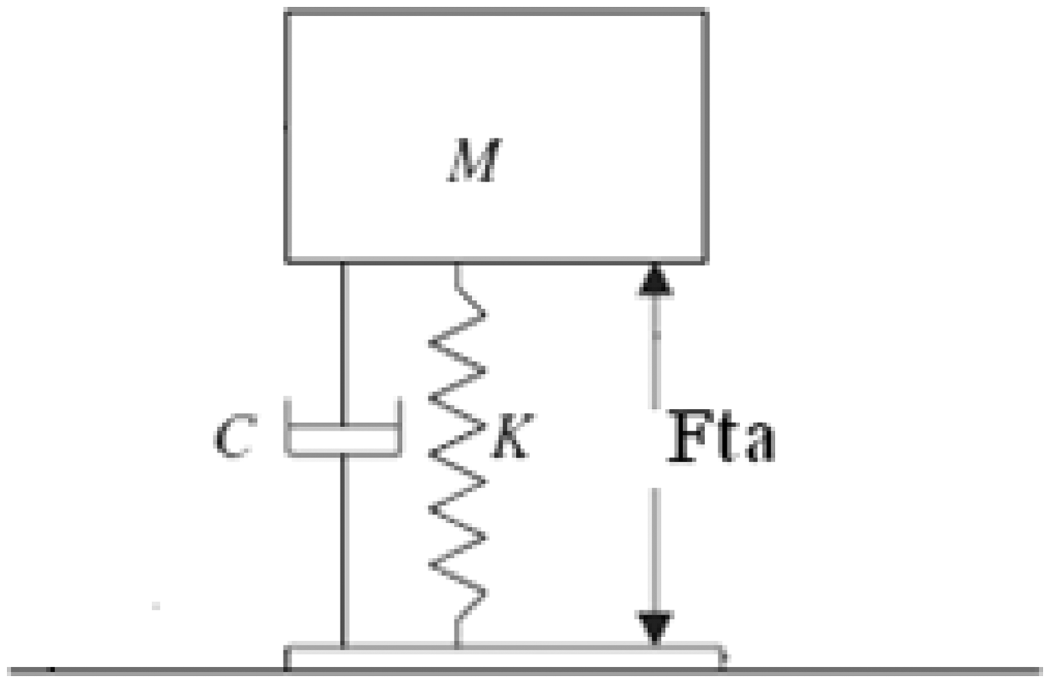
In this study, the engine supported by two rubber mounts and one active mount is considered. By employing the method presented in the previous study (Fakhari and Ohadi, 2012), linearized dynamic equations of motion of the engine on the mounts can be presented as follows:
In this study, the considered parameters for the engine and its mounts are presented in Appendix B. Also, the transfer function G20(s) for active part of the active mount is considered the same as the corresponding transfer function for a commercial active engine mount with a linear solenoid actuator. The mentioned transfer function has been identified by some experimental tests in a previous study, as shown schematically in Figure 3. In these tests, the active mount is loaded with a supported mass and is excited by sine wave current with constant amplitude and various frequencies using a function generator and a current amplifier. No displacement excitation is applied to the active mount. An accelerometer is attached on top of the supported mass to measure its acceleration. The transmitted force to the supported mass is calculated by multiplying its mass and the measured acceleration. By obtaining the transmitted force and knowing the applied current, the ratio of force amplitude to current amplitude is obtained for various excitation frequencies. Also, the phase difference between applied current and transmitted force to the supported mass in each excitation frequency can be obtained from experimental results. Finally, a transfer function G20(s) between input current and transmitted force can be fitted to the experimental results as below:
Schematic diagram of the experimental set-up for identification of the active part of the mount.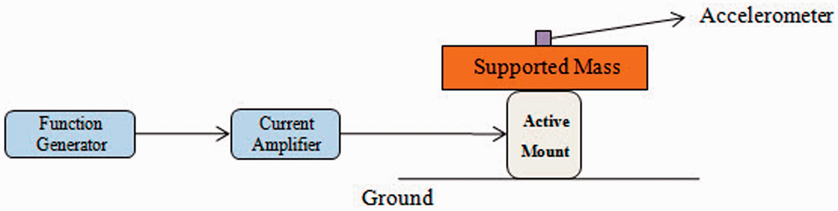
In addition, the considered parameters for the engine components (crankshaft, pistons and connecting rods) are adopted from the previous study (Fakhari and Ohadi, 2012).
In the next sections, three control algorithms (robust, adaptive and robust adaptive) are designed for the active mount to improve the vibration behavior of the engine on the mounts.
3. Robust control (H∞ scheme)
3.1. Backgrounds
Uncertainties can arise in the mathematical model of the physical systems. Therefore, employing the robust control schemes is necessary for real-world implementation of the controllers. In this study, one of the robust control algorithms, namely the H∞ control scheme, is considered.
The general block diagram of a control system with uncertainties is shown in Figure 4. In this figure, P(s) and K(s) denote the transfer functions of the plant and the controller, respectively. In addition, Δ indicates the uncertainties in the model. The vectors General block diagram of a control system with uncertainties.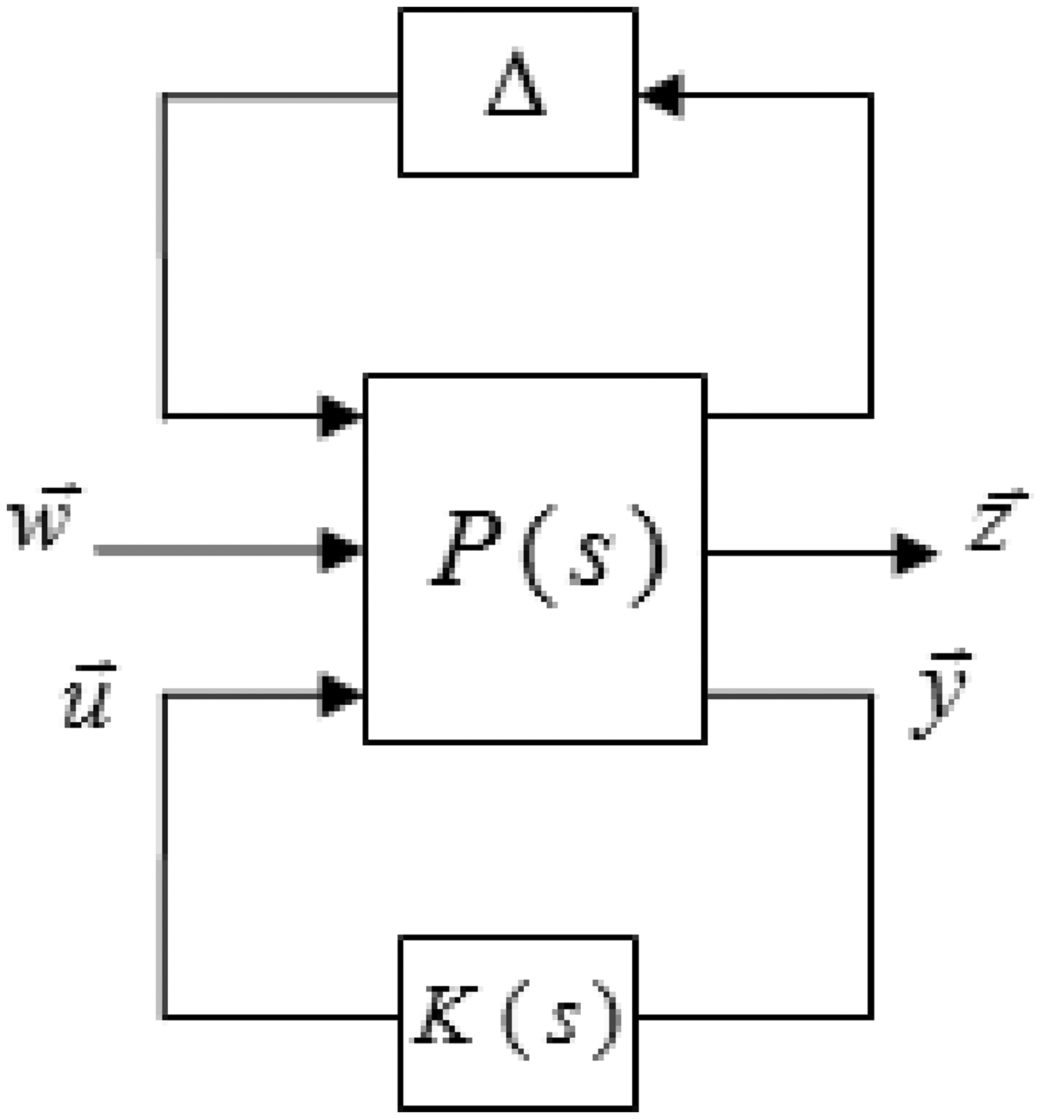
3.2. State-space representation
By considering the following state vector, the linearized dynamic motion equations of the engine on the mounts (considering the active mount model) can be presented in the state-space form:
The plant inputs are divided into two groups. The first group includes disturbance forces and moments (
The second group (u) is the applied current to the actuator of the active engine mount (control input), that is, u = I. In this study, it is assumed that the transmitted force to the chassis in the position of active mount in the vertical direction (Ft1z) is determined by a force transducer. The mentioned transmitted force is considered as the input signal to the controller.
3.3. Uncertainty representation
In practical situations, stiffness and damping properties of the mounts may be deviated from their nominal values due to the variations in manufacturing processes. In other words, the rubber material and geometry of the mount can be varied due to the manufacturing errors. This results in the variation in stiffness and damping properties of the mounts. The stiffness properties of the mounts can be varied by 30% of the nominal value due to the manufacturing processes and assembly variations (Weng, 2007). Therefore, in this study, the structured uncertainty in stiffness and damping properties of the mounts is considered to design the robust control. In this regard, the stiffness and damping matrices of the ith mount in its local coordinate system are presented as below:
By pulling out the uncertain parameters from the known part of the model, the uncertain model can be presented in the form of an upper linear fractional transformation (LFT), as shown in Figure 5, with a matrix Plant model in the form of an upper linear fractional transformation.
3.4. Performance requirements
The aim of the controller design is to reduce the transmitted force to the chassis in the position of the active mount in the vertical direction and also the prevention of actuator saturation in the presence of exogenous inputs (sensor noise and disturbances) in the range of engine operation (about 800–6000 rpm). In other words, it is necessary to reduce the transmitted force and limit the input current to the actuator. Therefore, the controller should minimize the effect of exogenous inputs on the transmitted force and input current to the actuator.
In robust controller design, the desired performance characteristics can be achieved by choosing the appropriate weighting functions. In this study, the disturbances (
A block diagram of the model of the engine supported by rubber and active mounts with the mentioned weighting functions (augmented plant) is shown in Figure 6.
Block diagram of the closed-loop system with the weighting functions.
3.5. H∞ control design
In order to design a robust controller, the disturbance forces and moments and sensor noise are considered as exogenous inputs (
By considering the state vector presented in Equation (12), dynamic equations of motion of the engine supported by the rubber and active mounts (Equations (8) and (9)) considering the weighting functions [Wd]6 × 6, Wn, Wu and WF are presented in the state-space form of Equation (11). Therefore, the model in Figure 6 can be presented in standard form as shown in Figure 4. In this study, the H∞ controller is designed using MATLAB, Robust Control Toolbox.
4. Model reference adaptive control
4.1. Backgrounds
The transfer function of the plant for the case of single input, single output can be represented as follows:
The control objective is to determine the plant input up so that all signals in the closed-loop plant are bounded and the plant output yp tracks the reference model output ym as closely as possible for any given bounded reference input r(t). The controller parameters are estimated online using an adjustment mechanism.
The control law, designed based on the modeled part of the plant, is presented as follows (Ioannou and Sun, 1996):
In this study, adaptive law based on the gradient method is employed to update the controller parameters Magnitude of the transmitted force (Ft1z) to control force (Fta) versus frequency with plant and reference model parameters.
The details of stability proof of the mentioned MRAC have been presented by Ioannou and Sun (1996).
4.2. Reference model
In this study, it is assumed that the displacement of the engine in the position of the active mount in the vertical direction is fedback to the MRAC controller. This can be obtained by double integration from acceleration of the engine in the position of the active mount in the vertical direction determined by an accelerometer.
The aim of the control is to reduce the transmitted force to the chassis. In order to achieve better vibration isolation in the closed-loop system, the passive stiffness and damping properties of the active mount defined in the reference model are considered to be smaller than those of the original system. In other words, the transfer function of the reference model is considered similar to that of the plant, but with smaller stiffness and damping for the passive part of the active mount. In this study, stiffness and damping properties of the passive part of the active mount in direction of actuation are 350,000 N/m and 374.7 Ns/m, respectively. The corresponding properties in the reference model are considered to be 100,000 N/m and 50 Ns/m. The Bode diagram (magnitude) related to the transfer function between the control force (Fta) and the transmitted force to the chassis in the position of active mount in the vertical direction (Ft1z) with the mentioned parameters for the plant and reference model are presented in Figure 7. It is clear that by employing the mentioned reference model, transmitted force to the chassis will be reduced in the frequency range of interest.
Time response of the transmitted force to the chassis in the position of the active mount in the vertical direction with and without robust MRAC at 3000 rpm.
In addition, for vibration isolation purposes, the reference signal is set to zero (r = 0).
4.3. MRAC design
As mentioned in Section 4.2, in this study displacement of the engine in the position of the active mount in the vertical direction is considered as a feedback signal to the MRAC. This can be obtained by double integration from acceleration of the engine in the position of the active mount in the vertical direction determined by an accelerometer. In simulation, double integration can be performed easily. However, in practice, double integration from the measured acceleration signal may lead to large integration errors. This is because of the accelerometer drift and unknown initial conditions for velocity and displacement. To solve this problem, high-pass filters (with very low cutoff frequency) are used in the process of integration. Double integration process includes two stages of integration and three stages of high-pass filtering. The first filter removes the accelerometer drift. The second filter removes the constant component (offset) from the velocity signal to eliminate the need for an initial velocity value. The third filter removes the low-frequency content from the position signal to eliminate the need for an initial position measurement. The mentioned process solves the problem of integration errors from the combined effects of accelerometer drift and unknown initial conditions (Slifka, 2004). However, filtering makes a relatively large phase shift in the obtained displacement signal from integration. This can easily destabilize the controller, if the models of the filters are not considered in controller design. Therefore, in this study models of the filters are incorporated with the plant model and the MRAC is designed to make the controller applicable in real-world implementation. In this regard, the transfer function of high-pass filters for double integration is considered as below:
Time response of the control current with application of robust MRAC at 3000 rpm.
In this study, transfer functions of the plant (G0(s)) and reference model (Wm (s)) for the considered engine on the passive and active mounts satisfy the assumptions presented by Ioannou and Sun (1996). Therefore, MRAC is designed using Equations (21) and (22) for control law and adaptive law, respectively. Also, the design parameters γ and
5. Robust Model Reference Adaptive Control
5.1. Background
Conventional adaptive control schemes such as MRAC are robust only in the face of parametric uncertainties and may become unstable in the presence of noise, disturbances and unmodeled dynamics. Because such modeling error effects will exist in practice, the nonrobust behavior of the mentioned controllers limits their applicabilities. This motivated many researchers to study the mechanisms of instabilities and find ways to counteract them. By the mid-1980s, several new designs and modifications were proposed and analyzed leading to a body of work known as robust adaptive control (Ioannou and Sun, 1996). In this study, one of robust adaptive control schemes, namely robust MRAC, is employed for vibration isolation using an active engine mount.
The plant model with multiplicative uncertainty and bounded disturbance can be presented as follows (for the case of single input, single output):
A1. Δm (s) is analytic in Re(s) ≥−δ0/2 for some known δ0 >0. A2. There exists a strictly proper transfer function W(s) analytic in Re(s) ≥−δ0/2 such that W(s) Δm (s) is strictly proper.
Moreover, it is assumed that the state-space form of the controller, the transfer functions G0(s) and
In conventional adaptive controllers (e.g. MRAC), adaptive laws (e.g. Equation (22)) are employed to update the controller parameters
The details of stability proof of the mentioned robust MRAC have been presented by Ioannou and Sun (1996).
In brief, the main difference between the robust MRAC and conventional MRAC is in the adaptive law. The robust adaptive law presented in Equation (25) for robust MRAC has additional terms
5.2. Uncertainty representation
In this study, the structured uncertainty in stiffness and damping properties of the mounts is used to design the robust MRAC (similar to the case of robust control design presented in Section 3.3). By considering Equation (15) for actual stiffness and damping parameters, the plant transfer function with uncertainties can be presented in the form of multiplicative perturbation shown in Equation (24). In this study, up to 50% uncertainty in the stiffness and damping properties of the mounts is considered for robust MRAC design, that is, pk = pc = 0.5.
5.3. Robust MRAC design
In order to design the robust MRAC, the feedback signal, reference model and reference input presented in Section 4.2 (for the case of MRAC design) are considered. In addition, the high-pass filter presented in Equation (23) is employed for the double integration process discussed in Section 4.3. In this study, transfer functions of the plant (G0(s)), reference model (Wm (s)) and multiplicative uncertainty (Δm(s)) for the considered engine on the passive and active mounts satisfy the assumptions presented by Ioannou and Sun (1996). Therefore, robust MRAC is designed using Equations (21) and (25) for control law and robust adaptive law, respectively. The design parameters γ and
In this way, at the start of applying the control, the values for σ1 and σ2 are large to counteract possible instabilities. After that, large values for σ1 and σ2 are not needed and maybe destroy the performance of the controller. Therefore, the mentioned parameters are decaying to smaller values by passing the time.
6. Simulation results and discussion
In this study, the engine supported by two rubber mounts and one active mount is considered. As mentioned in Section 2, the considered parameters in the simulation for the engine and its mounts are presented in Appendix B. Also, the parameters for engine components (crankshaft, pistons and connecting rods) are adopted from the previous study (Fakhari and Ohadi, 2012). In addition, the load torques and combustion pressure histories required for simulation are employed from experiments. It is noted that the mentioned data was available for engine speeds from 1000 to 6000 rpm with steps of 500 rpm. The vibration behavior of the engine on the mounts and performance of the active mount with the proposed controllers are simulated using MATLAB Simulink.
At first, a robust adaptive control algorithm, namely robust MRAC, is employed for the active mount to improve the vibration behavior of the engine on the mounts. The time domain response of the transmitted force to the chassis in the position of the active mount in the vertical direction with and without application of the robust MRAC is presented in Figure 8. The engine speed of 3000 rpm is considered. Results show that robust MRAC reduces the amplitude of transmitted force in the position of the active mount in the vertical direction at the mentioned engine speed. The corresponding control current and control force (Fta) in the time domain are shown in Figures 9 and 10, respectively.
Time response of the control force (Fta) with application of robust MRAC at 3000 rpm. Amplitude of the transmitted force to the chassis in the position of the active mount in the vertical direction for various engine speeds. Amplitude of the control current for various engine speeds.


In order to compare the robust adaptive control with the robust control algorithm, a robust control, namely the H∞ scheme, is employed for the active mount and performance of the mentioned controllers are evaluated and compared. The amplitude of the transmitted force at the position of the active mount in the vertical direction for various engine speeds with and without application of robust MRAC and H∞ control is shown in Figure 11. Also, Figures 12 and 13, respectively, show the amplitude of the control current and control force for various engine speeds with application of robust MRAC and H∞ control. The results show that both controllers reduce the transmitted force to the chassis. However, robust MRAC is more effective in reducing the transmitted force compared with the H∞ control at engine speeds above 2500 rpm. In other words, the control performance of the robust MRAC is better than that of H∞ control at high engine speeds. This is because of the fact that in the adaptive approach, the controller attempts to adapt to the dynamic characteristics of the plant and disturbances and, if properly designed, will eventually be the “best” controller for the considered plant. However, in the robust approach, the controller has a fixed structure that guarantees the “acceptable” (not necessarily the best) performance in the face of uncertainties and disturbances. Therefore, in general, robust adaptive control has better control performance compared with the robust control.
Amplitude of the control force (Fta) for various engine speeds. Transmitted force to the chassis in the position of the active mount in the vertical direction with and without MRAC; first case: 20% uncertainty in stiffness and damping of the mounts. Transmitted force to the chassis in the position of the active mount in the vertical direction with and without robust MRAC; first case: 20% uncertainty in stiffness and damping of the mounts.


In order to compare the robust adaptive control with the adaptive control algorithm, an adaptive control, namely MRAC, is employed for the active mount and robustness of the mentioned controllers are evaluated and compared. In this regard, uncertainty in stiffness and damping of all mounts in three directions is considered. As a first case, 20% decrease in nominal stiffness and damping properties of all mounts is considered and the MRAC and robust MRAC are applied. The time domain response of the transmitted force to the chassis in the position of the active mount in the vertical direction with and without application of MRAC and robust MRAC in the face of the mentioned uncertainty are presented in Figures 14 and 15, respectively. Results show that both MRAC and robust MRAC reduce the transmitted force in the presence of 20% uncertainty in stiffness and damping of the mounts.
Transmitted force to the chassis in the position of the active mount in the vertical direction with and without MRAC; second case: 30% uncertainty in stiffness and damping of the mounts. Transmitted force to the chassis in the position of the active mount in the vertical direction with and without robust MRAC; second case: 30% uncertainty in stiffness and damping of the mounts.

Then, robustness of MRAC and robust MRAC in the face of larger uncertainty is evaluated and compared. Therefore, as a second case, a 30% decrease in nominal stiffness and damping properties of all mounts is considered. Figures 16 and 17 show the transmitted force to the chassis in the presence of the mentioned uncertainty with and without application of MRAC and robust MRAC, respectively. The obtained results show that in the face of the second case uncertainty, MRAC cannot reduce the transmitted force and gradually is diverging. However, robust MRAC is robust in the presence of the second case uncertainty and reduces the transmitted force.
Transmitted force to the chassis in the position of the active mount in the vertical direction with and without MRAC; third case: 40% uncertainty in stiffness and damping of the mounts. Transmitted force to the chassis in the position of the active mount in the vertical direction with and without robust MRAC; third case: 40% uncertainty in stiffness and damping of the mounts.

Finally, a 40% decrease in stiffness and damping of the mounts is considered (as a third case uncertainty). Transmitted force to the chassis in the presence of the mentioned uncertainty with and without application of MRAC and robust MRAC are presented in Figures 18 and 19, respectively. The obtained results show that MRAC is not robust in the presence of the third case uncertainty and becomes unstable. However, robust MRAC is robust in the face of the third case uncertainty and reduces the transmitted force.
The considered variation of the engine speed versus time for simulation of the accelerating condition. Time response of the total transmitted force to the chassis in the accelerating condition without control.

It can be concluded that both MRAC and robust MRAC are robust in the presence of small uncertainties. However, in the face of large uncertainties, MRAC may diverge and become unstable, whereas robust MRAC is robust with respect to large uncertainties. It is noted that large uncertainties may arise in real-world implementation of the controllers. Therefore, robust MRAC is more applicable compared with MRAC.
In some driving conditions, the nominal speed of the engine is not constant. For example, when the driver is accelerating the automotive, the engine speed is increasing. Also, when the driver changes gears, the engine speed is changed. A proper control law for the active engine mount should be effective not only in constant engine speeds, but also in varying engine speeds. Therefore, in this study effectiveness of the robust MRAC in transient conditions (dynamic change in engine speed) is evaluated. In this regard, the accelerating and gear change conditions are considered and investigated. In order to evaluate and compare the results in the transient condition quantitatively, the RMS (root-mean-square) value of the signals is employed.
At first, the accelerating condition is investigated. It is assumed that the engine operates at constant nominal speed of 2000 rpm. Then, the engine speed is increased to 4000 rpm in two seconds by pressing the accelerator pedal, as shown in Figure 20. The total transmitted force to the chassis in the accelerating condition without and with application of robust MRAC is presented in Figures 21 and 22, respectively. RMS values of the total transmitted force without and with employing robust MRAC are 36.5 and 27.2 N, respectively. Therefore, the RMS value of the total transmitted force is reduced by about 25% by applying robust MRAC in accelerating condition. Results show that robust MRAC is effective and reduces the transmitted force to the chassis in the accelerating condition.
Time response of the total transmitted force to the chassis in the accelerating condition with the application of robust MRAC. The considered variation of the engine speed versus time for simulation of the gear change condition. Time response of the total transmitted force to the chassis in the gear change condition without control; 25% uncertainty in stiffness and damping of the mounts. Time response of the total transmitted force to the chassis in the gear change condition with application of robust MRAC; 25% uncertainty in stiffness and damping of the mounts.


As another transient condition, the gear change condition is considered. It is assumed that the engine operates at constant nominal speed of 3000 rpm in third gear. Then, the engine speed is suddenly decreased to 2000 rpm by changing into fourth gear, as shown in Figure 23. In addition, a 25% decrease (uncertainty) in nominal stiffness and damping properties of all mounts is considered. Figures 24 and 25 show the total transmitted force to the chassis in the gear change condition without and with application of the robust MRAC, respectively. RMS values of the total transmitted force without and with employing robust MRAC are 25.4 and 18.5 N, respectively. Therefore, the RMS value of the total transmitted force is reduced by about 27% by applying robust MRAC in the gear change condition. The obtained results show that robust MRAC reduces effectively the transmitted force to the chassis in the gear change condition and in the presence of uncertainty.
Therefore, robust MRAC is effective in reducing the transmitted force not only in constant engine speeds, but also in transient conditions.
7. Conclusions
In this study, a robust adaptive control was employed for an active engine mount in a six-degree-of-freedom model of the engine on the mounts to improve vibration behavior of the engine. The vibration isolation performance and robustness of the employed robust adaptive control were compared with a robust and an adaptive control. In addition, effectiveness of the robust MRAC in transient conditions was evaluated. A dynamic model for the engine supported by rubber and active mounts and its governing equations were presented. Then, a robust adaptive control, namely robust MRAC, based on the gradient method with σ-modification was designed by selecting a proper reference model. Also, structured (parametric) uncertainties in stiffness and damping properties of all mounts in three directions were considered. Performance and robustness of the robust MRAC were compared with a robust control (H∞ scheme) and an adaptive control (MRAC) in the face of small and large uncertainties. Simulation results show that robust MRAC is effective in reducing the transmitted force to the chassis. Moreover, robust MRAC has better control performance compared with the H∞ scheme. In addition, in the face of large uncertainties, MRAC may diverge and become unstable. However, robust MRAC is robust in the presence of large uncertainties. Based on the simulations results, robust MRAC is effective not only in constant engine speeds, but also in transient conditions. In this study, one active mount was employed for vibration isolation of the engine on the mounts. One active engine mount cannot reduce effectively total transmitted force to the chassis. By employing two active mounts, vibration behavior of the engine on the mounts is improved. Therefore, investigation on effectiveness of employing two active engine mounts for vibration control of the engine is proposed for future study.
Footnotes
Acknowledgment
The authors gratefully acknowledge the IPCO research center for supplying the required data for engine and rubber mounts.
Funding
This research received no specific grant from any funding agency in the public, commercial or not-for-profit sectors.