
Abstract
This article presents multiple channel estimation (MCE) that is a multi-sensor access wireless system model. An avionics wireless system needs a power control device to match the power received from the multiple sensors. Without a power control device, the aircraft control unit is unable to receive the signals from sensors due to signal reflections, refraction and transmission loss. The MCE system is designed to suppress multi-sensor signal noise and interference while a sensor, with lower power than the other sensors, is received. This article investigates overcome the power difference based on the MCE system. The performance of proposed MCE model is investigated and validated for a safe indoor avionics wireless system and it improves the overall performance of the wireless system to perfect power stability.
1. Introduction
Avionics wiring systems require 78% of power consumption to transmit the data to a receiver (Tooley and Wyatt, 2009). One of the methods to reduce the power consumption in avionics systems is to develop the wireless system services to provide reliability, flexibility, functionality and immunity to interference (Plass, 2011). Existing avionics indoor wiring system solutions are not optimized for power optimization and power efficiency is erratic (Stacey, 2008). The cost of avionics wireless system equipment reduces the total cost in an aircraft. The data interactions within an indoor aircraft avionics system for navigation and surveillance pass the control functions from transmitter to receiver through a wire link. The difficulty of this transmission is risky if the wire breaks (Spitzer, 2006a).
The Boeing 787 operates a dual 100–Mbps fiber local area network (LAN) system with multiple copper 10–Mbps Ethernet sub-LANs (Boeing, 2013). This is 900 times faster than the maximum data speed achievable on ARINC systems (Spitzer, 2006b). The weak spot in its reliability is the bus controller failure. Another problem is the ARINC systems coupling which uses hard wiring transformer coupling (ARINC, 2012). When faults occur, it is evident that the loss of avionics function or the avionics system failure is due to the bus problem. The ARINC system problems are associated with the bus wiring (ARINC, 2011). Maintenance of fiber and copper components of this system is expensive, requiring an extensive use of additional test equipment (Airbus, 2010). Airbus A380 aircraft has the fiber distributed data interface (FDDI) interface. In addition, the FDDI technology is more expensive (Airbus, 2013). This is a full duplex 100–Mbps LAN and switched Ethernet communications subsystem. The common point of failure in most of the communication systems is the power supply (Aviation Safety Network, 2013a).
Airframe systems such as landing gear control and indication, and control surface position require various sensors for monitoring and control of airframe systems. The nonlinear vibration suppression technique was robust and efficient and it functioned with most sensors and actuators (Garg and Anderson, 2003). The size and location of the piezoelectric actuators are two issues to guarantee the highest energy efficiency and controllability of the system (Fariborzi et al., 1999). The safe operation of an aircraft is becoming dependent on avionics systems. These systems are all interconnected with wires and cables (Logan, 2013). This is followed by direct ongoing inspection and maintenance requirements for continued airworthiness. System reliability will be seriously affected by wiring that has not been correctly installed or maintained (Dornheim, 2001). The appropriate location of the sensors has to be considered for system observability and minimum noise sensor output ratio (Fariborzi et al., 1999).
Aircraft systems need to distribute the electrical power safely for efficient control of the aircraft (Airbus, 2012). The wires and cables must be protected from overload conditions that could lead to overheating, causing the release of toxic fumes, possibly leading to fire (Field, 2001). Wire and cable installations cannot be considered as units that when once fitted, can be left unsupervised. System reliability is affected by wiring that has not been correctly installed or maintained (Liu, 2008). Aircraft systems need to be controlled and/or monitored either manually or automatically.
The placement of control devices and sensors is very important to improve the effectiveness of control strategies (Cha, 2013). There is a need to develop and design sensors that can easily be installed on aircraft and provide accurate measurements of the surrounding flow as required for controlling and maneuvering the flights (Ghommem et al., 2013). It is extremely important to determine sensor locations for the processes which need to be controlled. The two most reliable methods for determining the sensor are the improvement of state controllability and observability of the process (Van de Wal and De Jager, 2001). The sensor selection can be used to reduce the cost of operation and maintenance, even if all the variables can be manipulated and measured. The problem of determining the sensor locations is viewed as the problem of maximizing the output energy generated by a given state (Shaker and Tahavori, 2013). Separate sensors may be placed in separate parts of the beam to sense each mode but this is not the optimal method. It is better to control the output from the sensors in software and the estimation of the modal responses from the sensor outputs as well conditioned as possible (Friswell, 1999). It is virtually impossible to ensure that the power source will be perfect at all times (Aviation Safety Network, 2013b). Failures within a system can also cause irregular power levels.
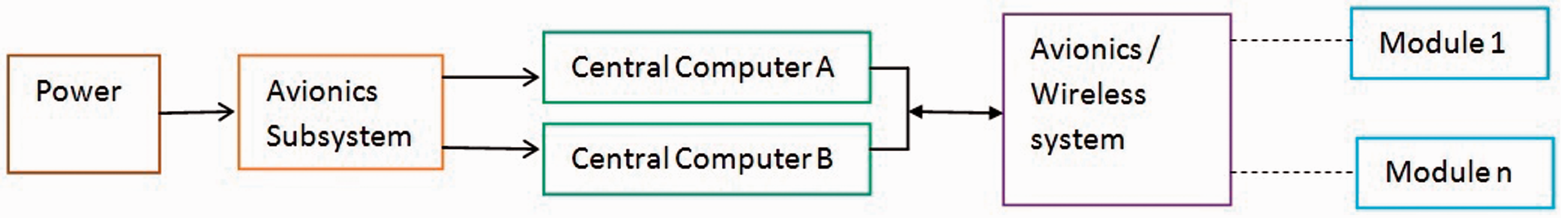
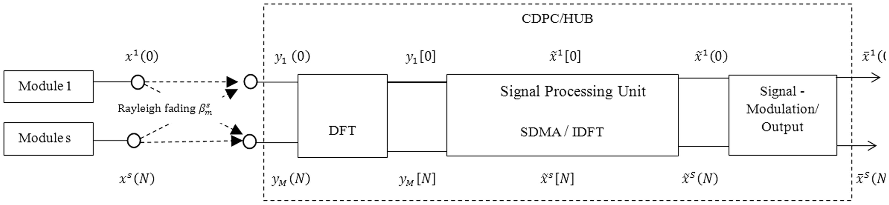
This paper describes the wireless system model in which protection from overload conditions before power is distributed to the various loads or module on the aircraft is available. The distribution control unit comprises the protection, control, wiring and loads unit. An existing avionics system is shown in Figure 1. Replacing the avionics system by an avionics multiple channel estimation (MCE) wireless system can reduce the wiring of aircraft weight and also improve the safety of the aircraft. A proposed avionics MCE wireless system is shown in Figure 2, it reduces the hardware installation and maintenance cost. The MCE method has been developed for aircraft indoor avionics wireless systems and its system model is shown in Figure 3. It considers multiple reflections and transmissions of the propagated waves and predicts the propagated signal with accuracy. The wireless system is responsible for the communication and receives interrupts associated with power failure and hardware error to direct necessary actions to enable recovery. The quality of the model depends on the mathematical models chosen, the measurement error in the data, the number and location of sensors, the excitation and response bandwidth (Papadimitriou et al., 2000).
Existing avionics system in aircraft (Boeing 787). Proposed avionics multiple channel estimation wireless system. System model of multiple channel estimation avionics wireless system.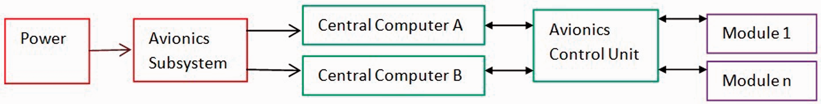
2. Multiple channel estimation avionics wireless system
The channel estimations, carrier frequency and data symbol timing are the elements of the space division multiple access (SDMA) system. The channel estimation of multiple sensors is based on transmitting symbols and frequency division. Different sensors transmit data symbols on each carrier and it separates by decorrelating the filter at the receiver. Moreover, the performance of SDMA system gets corrupted due to power control and it also introduces channel estimation problems. The MCE method reduces channel estimation problems by the MCE algorithm. The multi-senor channel estimation problem cracks into single-sensor channel estimation problems. The single-sensor MCE algorithm develops the time domain channel impulse response. The received signal synchronization problem mismatches sensors’ synchronization parameters. This problem is overcome by separating the signals from distortion in the SDMA processor. The vibrational energy of that particular mode is at a maximum and sensors placed at these locations are extremely effective at estimating that particular mode. To determine an effective sensor configuration is to find the areas of energetic modal activity (Cohen et al., 2004). Since there are usually some limitations on the location of sensors, collocation of sensors is not possible (Rastgaar et al., 2009). To detect erroneous measurements a filtering algorithm was applied locally at each sensor (Elmenreich, 2007). The distortion is produced by the sensor’s mismatch, and this problem is reduced by the MCE algorithm. Hence, sensor synchronization techniques compensate the sensor terminals for synchronization mismatches before transmission and reduce the distortion. Power control is a problem associated with SDMA detection due to inequality in the power received from different sensors. SDMA processor regulates power received from the sensors.
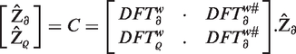
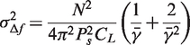
Space division multiple access is a multi-sensor access technique. It needs a power control device to match the power received from multiple sensors. Without a power control device, the HUB is able to receive the signals from nearby sensors only, due to signal reflection and transmission loss. This article investigates how power difference may impose on the performance of MCE (wireless system) algorithms. This MCE wireless system (algorithm) conquers multi-sensor interference and noise. When there are differences in the power transmitted by the sensors, MCE wireless system and its algorithm detect and suppress the noise and interference and ensure perfect power stability.
2.1. Multiple channel estimation (MCE)-space division multiple access (SDMA) algorithm
Multiple model adaptive control (MMAC) algorithms have been applied (Maybeck and Pogoda, 1989) with four elemental controllers to sensor failure detection and control reconfiguration in the STOL F–15 aircraft. This application of the MMAC algorithm is extended with seven elemental controllers for a healthy aircraft, three actuator failures, and three sensor failures (Maybeck and Stevens, 1991). The key point in MMAC is to design good elemental controllers to provide desirable vehicle behavior for the particular failure status of sensors only. Furthermore, the system is monitored through adaptive least-mean-squares (LMS) modelling, and sensor failures detected with adaptive analysis (Ni and Fuller, 2000, 2003). These algorithms are not suitable for wireless sensors.
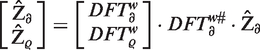
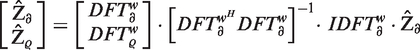
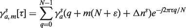
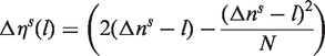
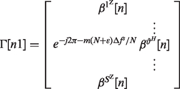
The single sensor channel estimation problem is resolved by the channel estimator. Consider the channel measurements
3. Wireless data synchronization
Wireless data synchronization inequalities activate the data interference and distortion. The multi-sensor receiver balances data synchronization inequalities in the sensor receiver. The environment does not guarantee optimal performance every time, especially when an obstacle interferes with the ultrasonic sensor’s detection ability. To have real time obstacle avoidance ability (Fahimi et al., 2009), the air route surveillance radar (ARSR) needs an online communication function (Peyrard, 2008). Hence, future work could be done using wireless data transmission devices (Valera et al., 2007) to give the ARSR the ability to have real time obstacle avoidance functions (Chen et al., 2011). The proposed SDMA-MCE algorithm performs a signal separation after the Fourier transform. Transceiver data symbol synchronization (TASS) refers to originality of the received data at the sensor receiver and hub with the OFDM symbol stream. The transceiver carrier frequency synchronization refers to the compensation of the carrier frequency offset between the transmitter and receiver (HUB). The transceiver clock frequency synchronization refers to the compensation of the sampling clock frequency offset between the sensor’s transmitter and receiver. These tasks are investigated in Sections 3.1, 3.2 and 3.3 respectively.
3.1. Transceiver data symbol synchronization (TASS)
Wireless sensor networks permit the decentralized instrumentation of large constructions eliminating the need to route expensive lengths of cable to locations distributed spatially distant from the host data. Incorporating signal conditioning hardware and signal processing with a chip transceiver directly at the sensor has the additional benefit of eliminating electromagnetic field noise pickup and impedance generated measurement errors associated with long cable lengths. It also significantly reduces the labor in installation and removal of sensor installations. The advent of the second generation chip transceivers enabling data rates up to and in excess of 250 kbps has the real time streaming of relatively large networks of vibration measurements theoretically feasible in the wireless platform (Whelan et al., 2011).
The transceiver data symbol synchronization is the timing of the signal streams
The transmitted signal
3.2. Transceiver carrier frequency synchronization (TCFS)
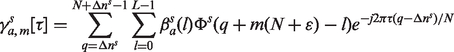
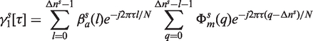
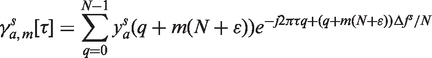
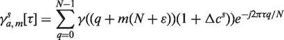
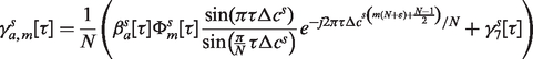
Multi-sensor frequency synchronization refers to the problem of aligning the carrier frequencies of all sensors to the base station. The carrier frequency aligning problem divides into multiple single-sensor problems and this problem is solved based on MCE algorithms. The carrier frequency of sensor s is denoted by a normalized frequency
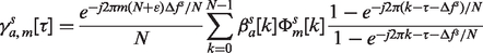

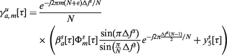
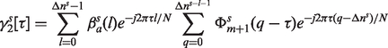
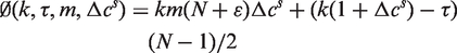
Equation (18) exposes that the contribution of the
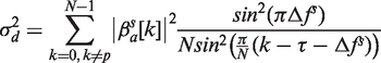
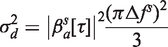
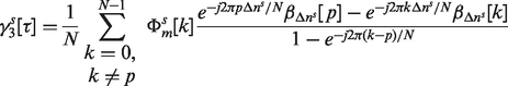
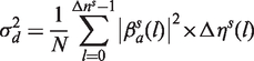
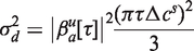
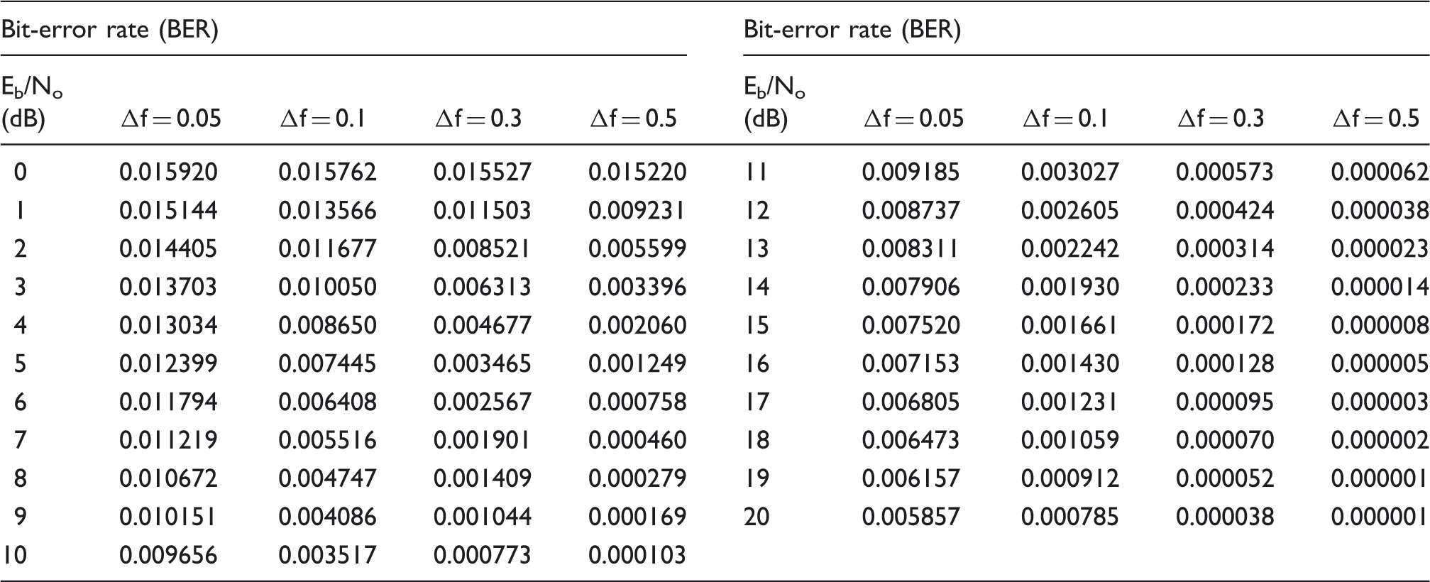
Equation (21) indicates that the distortion power on subcarrier p is equal to the power of the channel response coefficient and the square of the normalized frequency offset. Distortion is caused by the offset of a sensor s. This is spanned by the channel coefficient vector
The distortion due to Performance of frequency offset on multiple channel estimation-SDMA.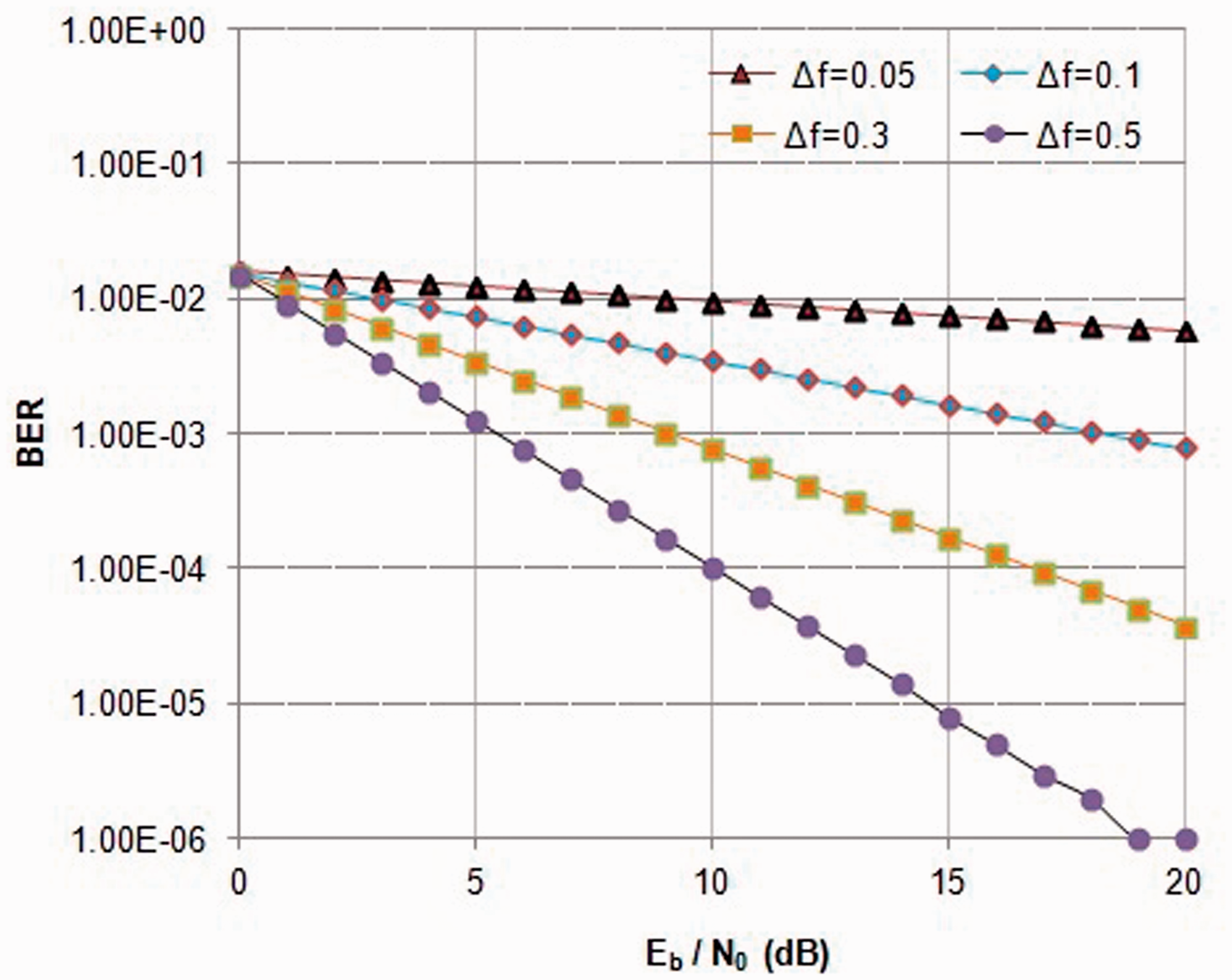
The accuracy and gain of correlation-based

3.3. Receiver sampling clock synchronization (RSCS)
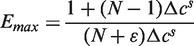
The energy consumption of each node was monitored to identify when to replace batteries and investigate the reliability of the wireless sensor network monitoring system by analyzing the arrival rate of periodically generated data (Feltrin et al., 2013). The receiver clock frequency offset of sensor s is denoted by

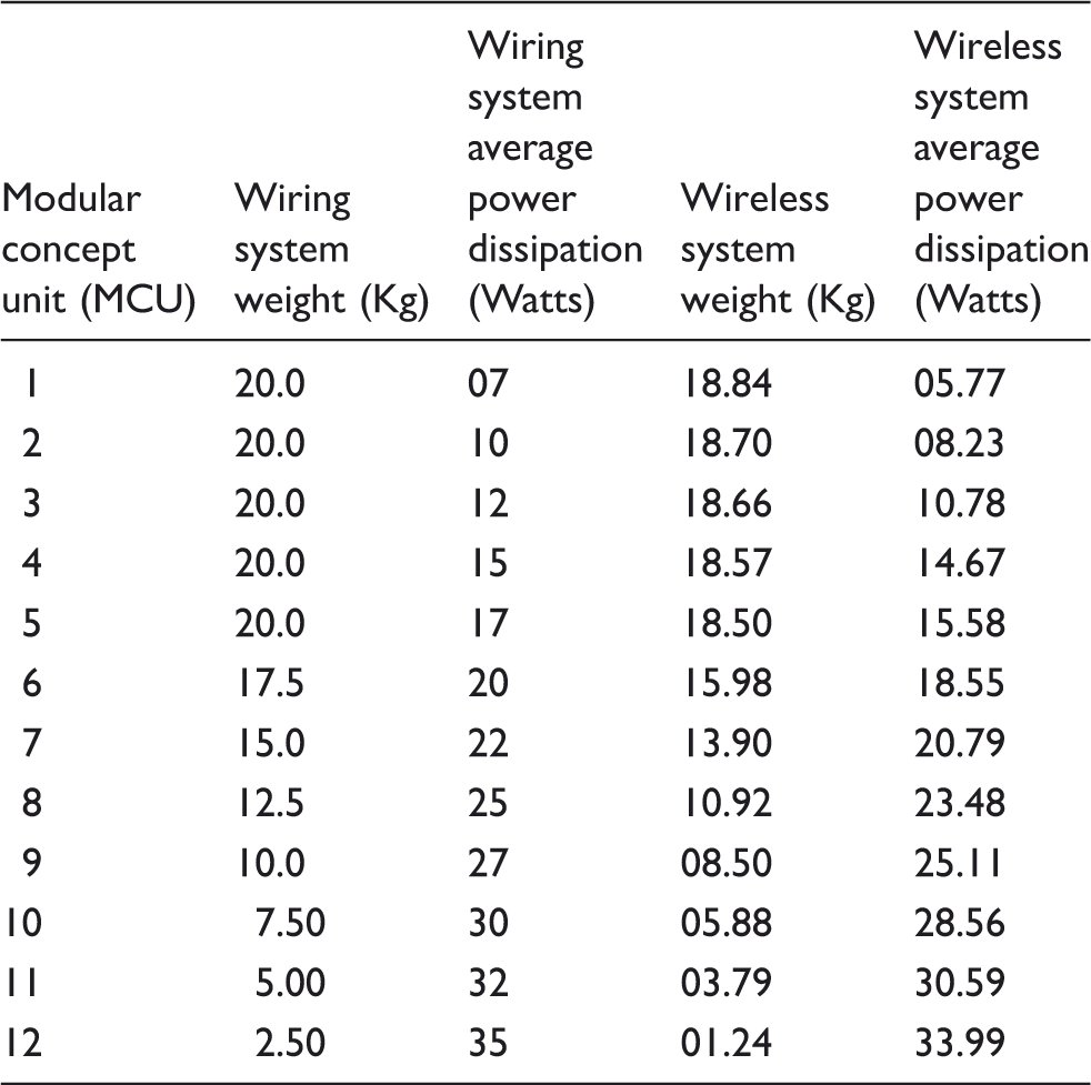
Average weight and power dissipation for avionics wiring system.
The distortion due to carrier frequency offset and a sampling clock frequency offset are the same. In practical systems both carrier frequencies and sampling clock frequency are derived from the same crystal oscillator. Therefore, this can be expressed by (31). The ratio of the distortion powers
4. Simulation results
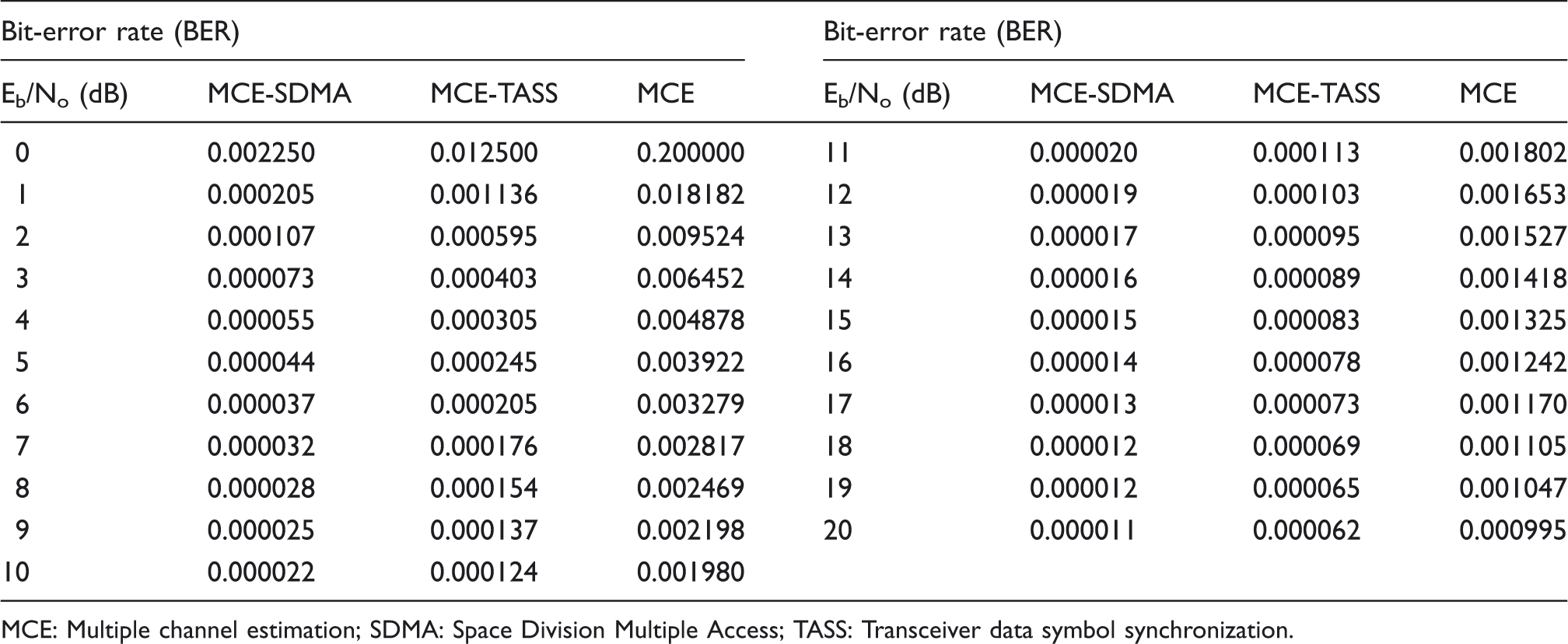
Simulation results to measure the performance of the SDMA-MCE algorithm are based on the multiple channel estimation method. In the proposed MCE approach to 400 sensors and 50 antennas SDMA with OFDM data symbol, a synchronization approach is adopted, in which the sensor terminals pre-compensate their data symbol mismatches before transmission to reduce distortion. After reception of the transmitted data symbol, the HUB applies the MCE algorithm on the 50 subsets of subcarriers, to obtain the channel responses from all sensors to all HUB antennas. The performance of MCE, MCE-TASS and MCE-SDMA is shown in Table 2. The resulting bit-error rate (BER) vs. received Performance of multiple channel estimation-SDMA with channel estimation. Performance of MCE, MCE-TASS, MCE-SDMA. MCE: Multiple channel estimation; SDMA: Space Division Multiple Access; TASS: Transceiver data symbol synchronization.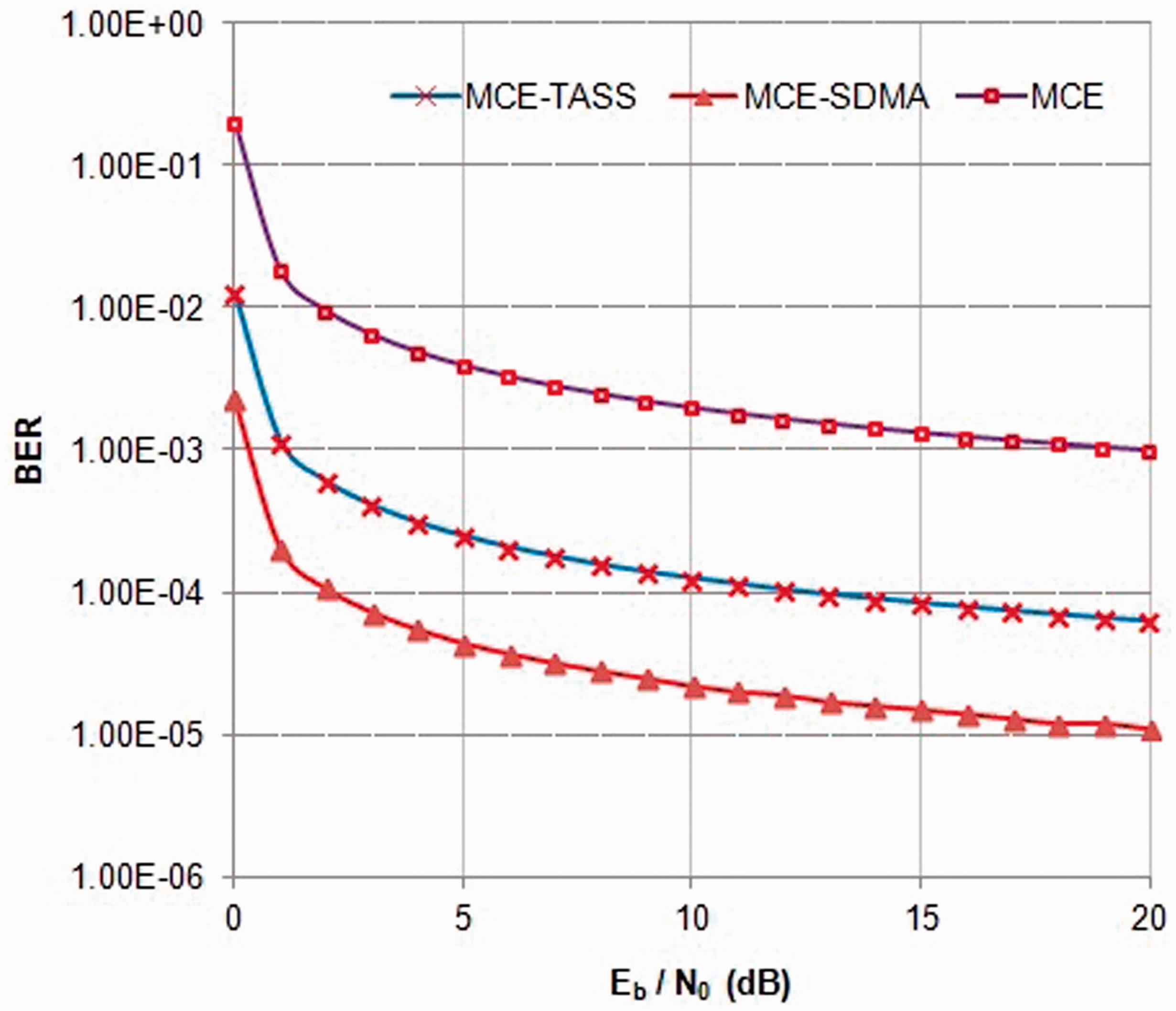
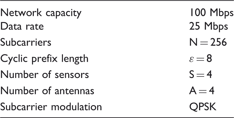
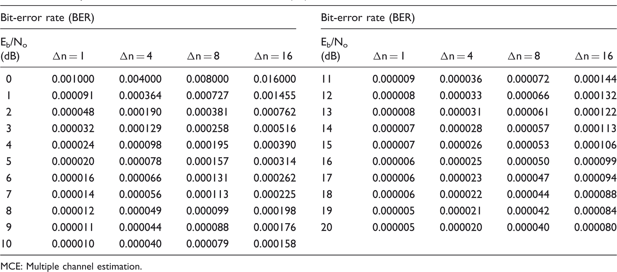
The performance degradation is 0.9 dB for 100 sensors in the MCE method. Hence, it reduces the error propagation problem of interference cancellation. Figure 5 shows the BER performance for sensor 1 with the data symbol offset Performance of a data symbol offset on multiple channel estimation-SDMA. Specification for aircraft local area network (ALAN). Data symbol offset on MCE-SDMA - BER Vs. Eb/No(dB). MCE: Multiple channel estimation.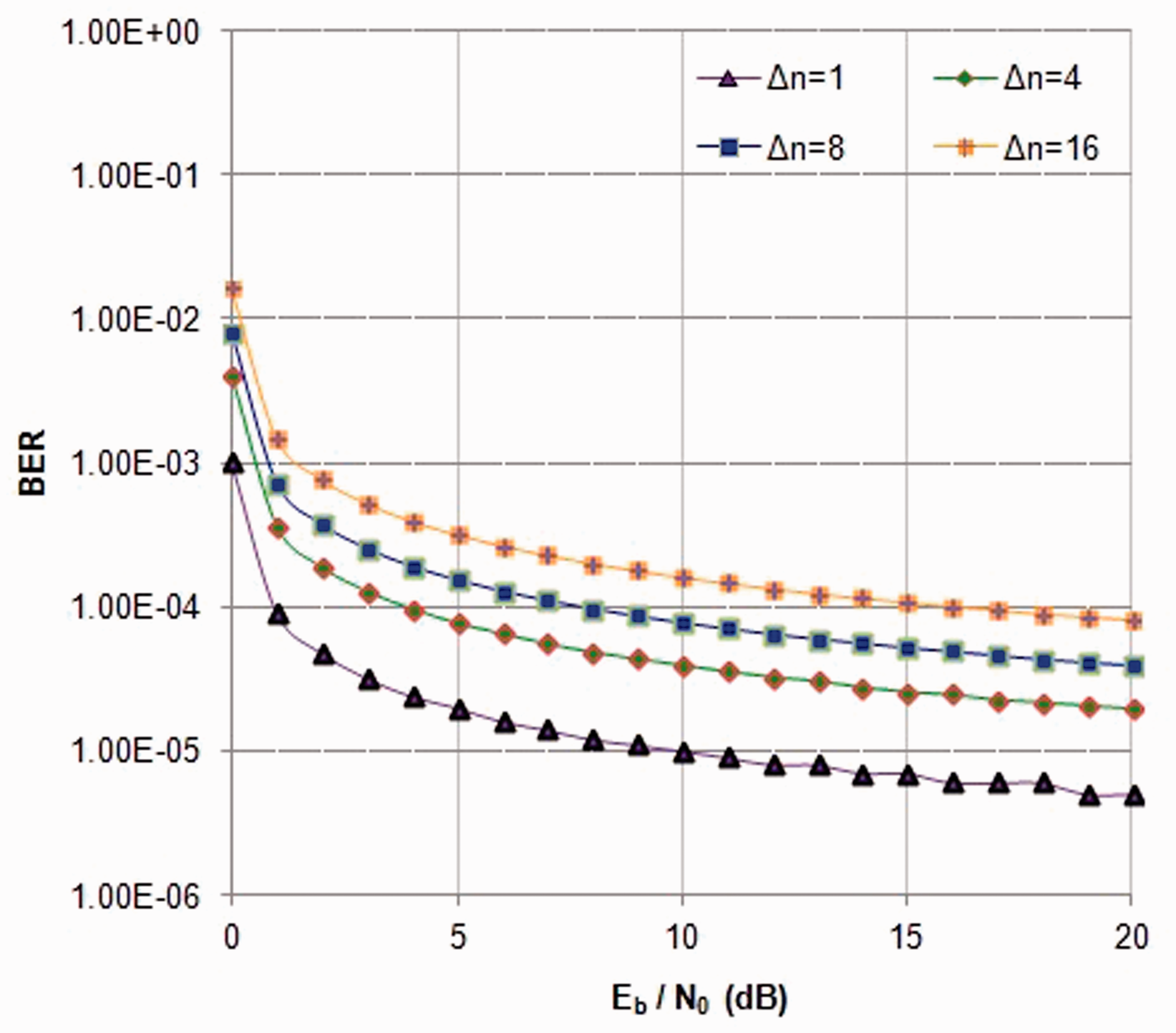
Frequency offset on MCE-SDMA - BER Vs. Eb/No(dB).
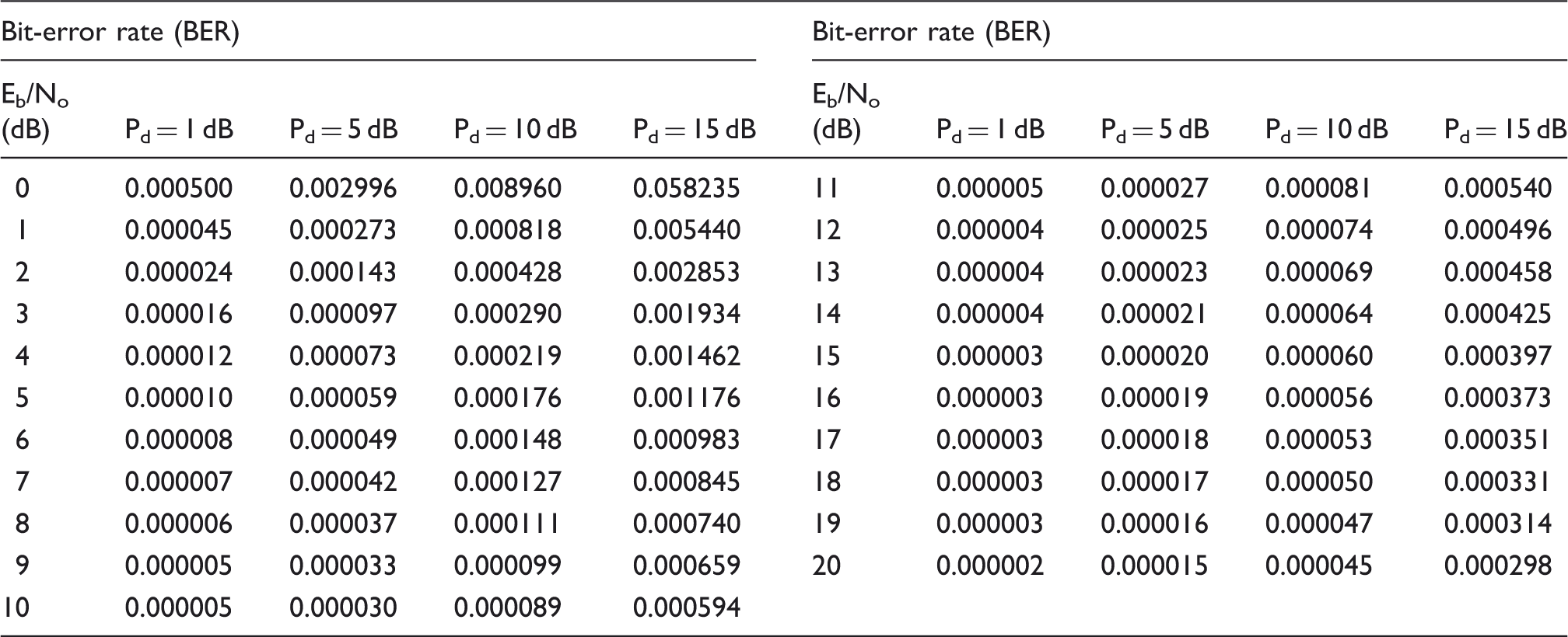
The MCE algorithm detects the sensors’ signals sequentially by power received on each subcarrier. After detection, the strongest signal received by a sensor is reconstructed and subtracted from the actual received signal. Therefore, the remaining weaker sensors do not experience this strong sensor’s interference and can exchange interference for noise reduction and better performance is achieved in the next iteration. This is demonstrated in Figure 7, which presents simulation results for a 400 sensors 50 antennas system with the power difference (Pd) as a parameter specified in Table 6.
Performance of multiple channel estimation-SDMA with perfect power control. MCE-SDMA with perfect power control - BER Vs. Eb/No(dB).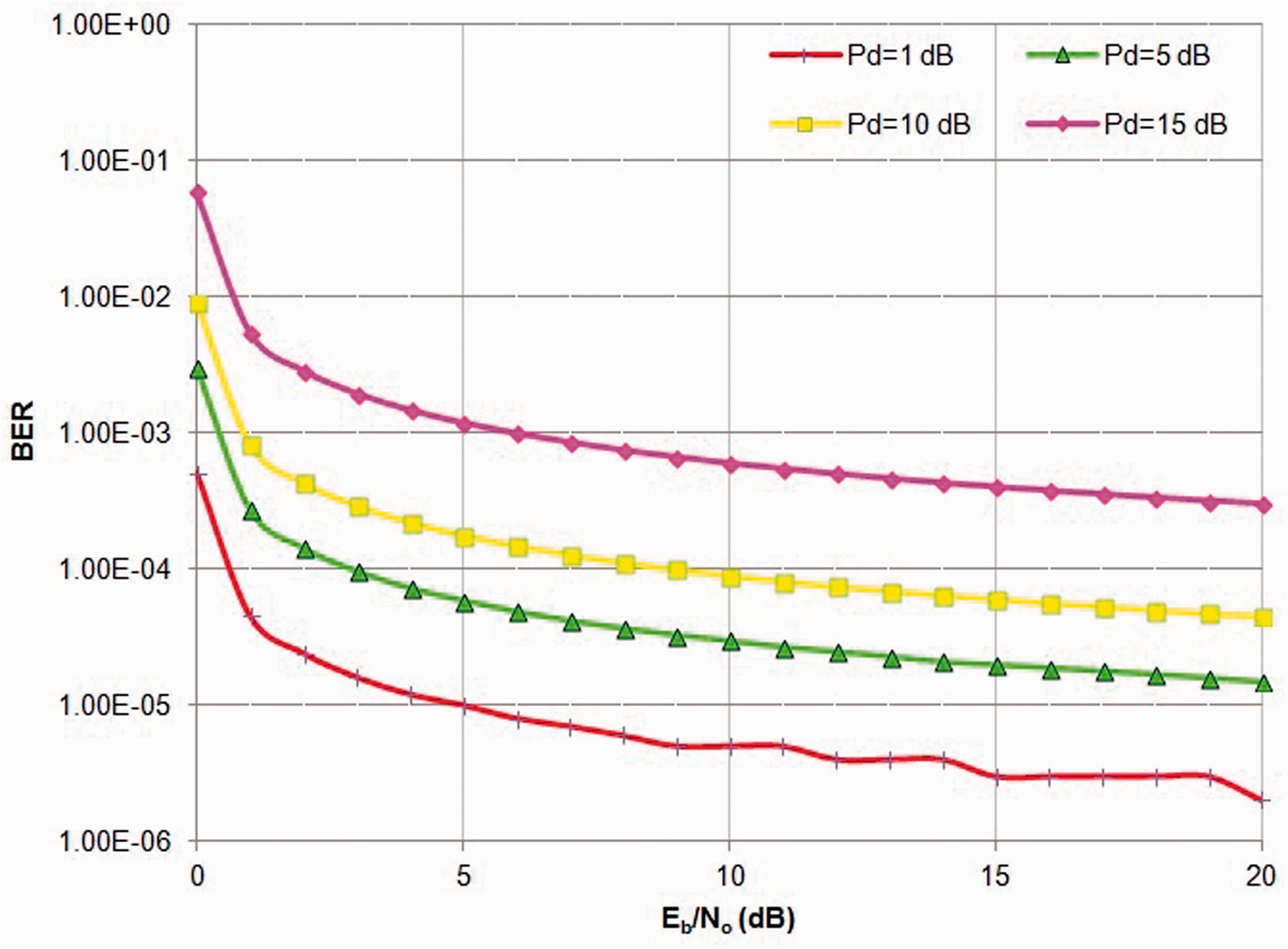
5. Conclusions
The aircraft indoor wiring problems encountered when building a wireless system for aircraft indoor wireless sensor communication and MCE-SDMA techniques are investigated. The proposed MCE method splits the multi-sensor channel estimation problem into several single-sensor problems. The resulting single sensor channel estimation problems are overcome by the MCE-SDMA algorithm that allows the estimation of the full channel based on measurements on subcarriers. Hence, the performance of proposed MCE model improves the overall performance of the wireless system with perfect power stability.
Footnotes
Funding
This work was supported by the AICTE-RPS, Government of India (grant number 20/AICTE/RIFD/RPS(POLICY-II)18/2012-13,Dt:20.01.2013).