This paper proposes the use of inverse disturbance response decoupling (DRD) for an optical table to suppress vibration in precision machinery. Optical tables are normally adopted in precision engineering to repress two vibration sources: ground disturbances from the environment and load disturbances from machines. The suspension settings for restraining these disturbances are conflicting; therefore, in previous studies, we developed a DRD structure that could independently control the disturbance responses: using soft passive elements to isolate the ground disturbances and improving the load responses by active control. This paper extends these ideas by proposing an inverse DRD structure that uses stiff passive elements to suppress load disturbances and improve ground responses by active control employing robust loop shaping techniques. The designed inverse DRD structure and controllers are implemented and verified by experiments. Based on the results, the proposed inverse DRD structure and robust control are deemed effective in improving the performance of an optical table.
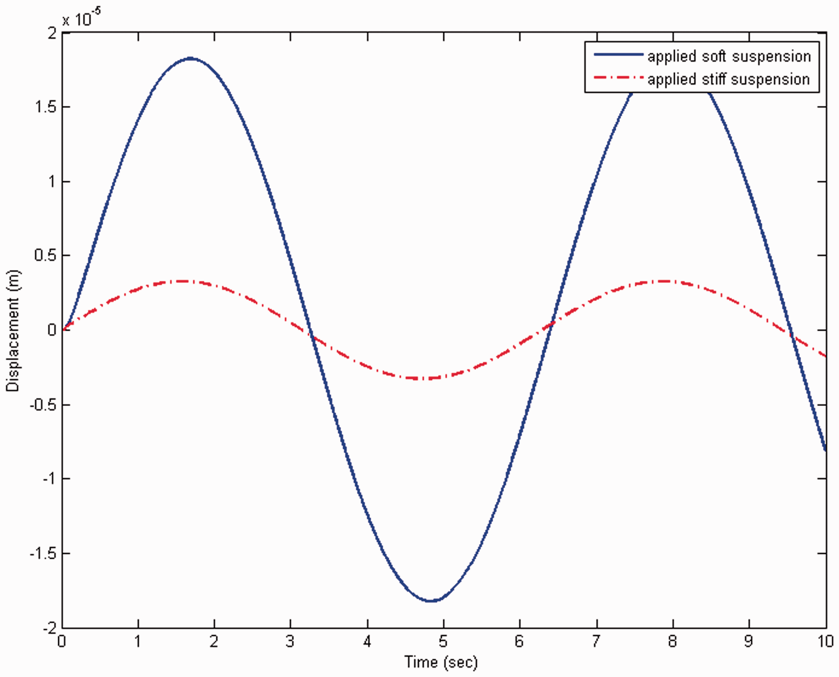
Vibration control is critical for precision engineering. Therefore, optical tables are normally applied to suppress system vibrations. For example, the TMC Gimbal Piston™ (Technical Manufacturing Corporation, 2013) utilizes a passive pneumatic spring/damper to isolate ground disturbances. Active optical tables are applied to further improve system performance by means of sensors and actuators (Kato et al., 2010; Chang et al., 2010; Oh et al., 2012). Generally speaking, an optical table needs to suppress two kinds of disturbances: load disturbances from the machines and ground disturbances from the environment. Because the settings for isolating these disturbances are conflicting (i.e., they need to be soft for isolating the ground disturbances and stiff for suppressing load disturbances), the suspension parameters of an optical table are normally a compromise between these requirements. Therefore, Wang et al. (2012a) developed a double-layer optical table, as shown in Figure 1, which employs disturbance response decoupling (DRD) techniques for independent control of these two disturbances: using soft passive elements to isolate the ground disturbances and improving the load responses by active control. The designed structure and controllers were implemented and shown to achieve the DRD effects. This paper considers the system’s responses to load disturbances, and proposes an inverse DRD structure that can effectively suppress load disturbances by stiff passive elements. For example, as illustrated in Figure 2, the responses of the optical table in Wang et al. (2012a) to a 1 N sinusoidal load disturbance are significant because of the soft passive elements. We can greatly reduce the table vibrations by replacing the original soft passive elements (i.e., the Newport™ I-2000 pneumatic LabLegs™) with a stiff stand . The developed inverse DRD structure can then improve the ground responses by active control without influencing the achieved load responses.
Vibration suppression of load responses by stiff suspensions.
The remainder of the paper is arranged as follows: Section 2 derives the inverse DRD structures for an optical table. Section 3 obtains transfer functions of system elements by experiments. Section 4 designs robust loop shaping controllers that can improve the ground responses without affecting the load responses. Section 5 implements the designed inverse DRD structures and robust controllers for experimental verification, and demonstrates the effectiveness of the proposed design. Lastly, we draw conclusions in Section 6.
2. Optical table with inverse disturbance responses decoupling
In this section, we derive the inverse DRD structures of an optical table that can isolate the load disturbances by stiff suspensions and improve the ground responses without influencing the load responses.
2. 1. The quarter-table
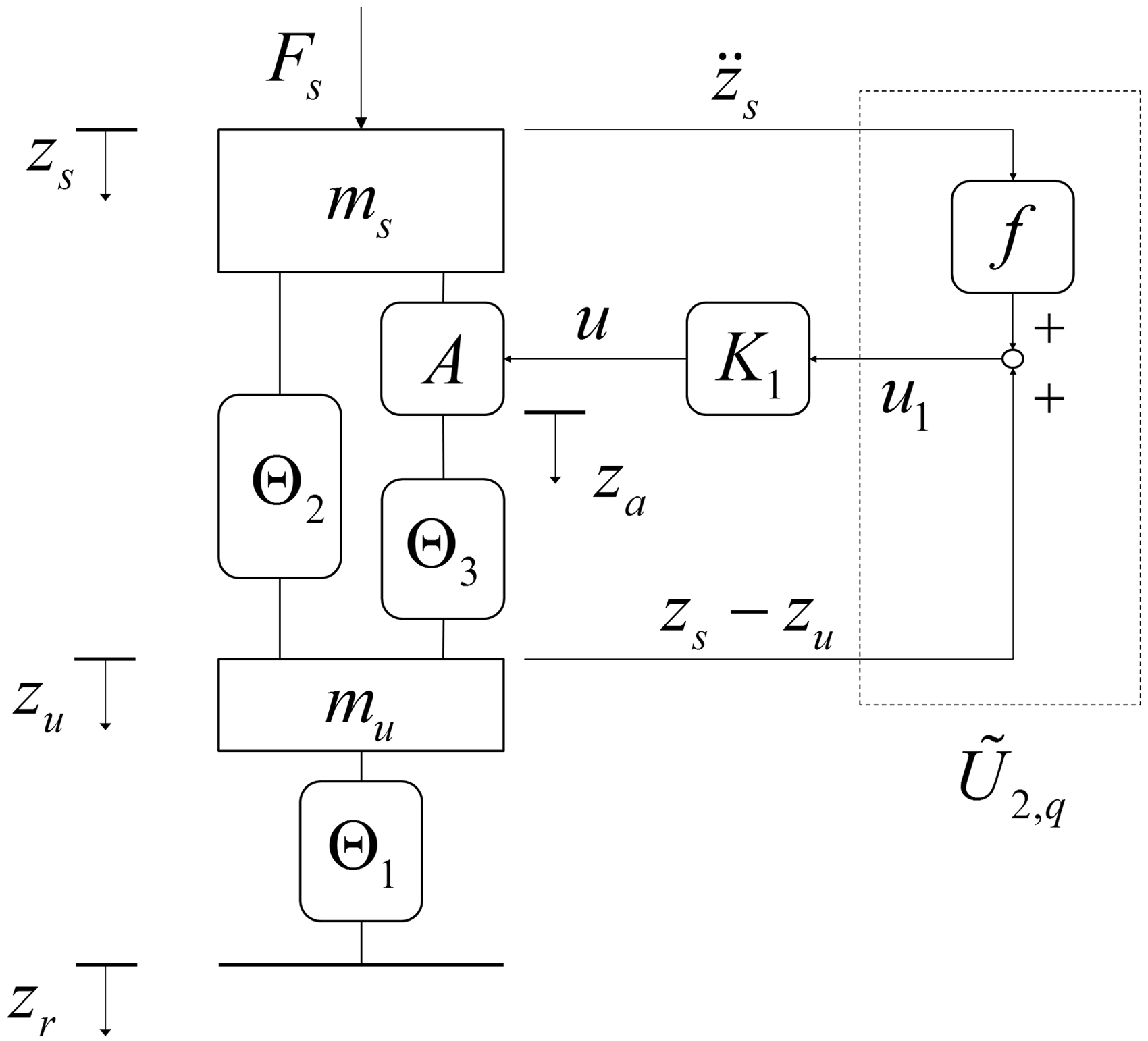
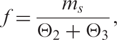
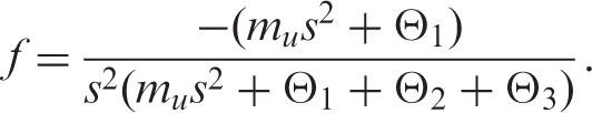
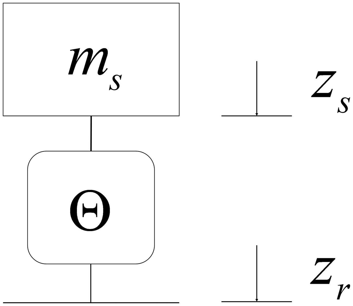
We first consider a quarter-table, as shown in Figure 1, in which A is an actuator; and f is the inverse DRD filter, with the following dynamic equations:
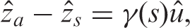
where Fs and zr are the load disturbance and ground disturbance, respectively; , , and represent passive suspension structures. The actuator controls the relative displacement across its two terminals, as follows:
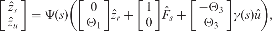
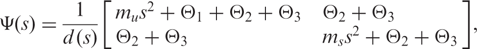
in which represents the actuator dynamics and “^” represents the Laplace transform. Taking Laplace transform of (1–2), the quarter-table model can be represented as
where
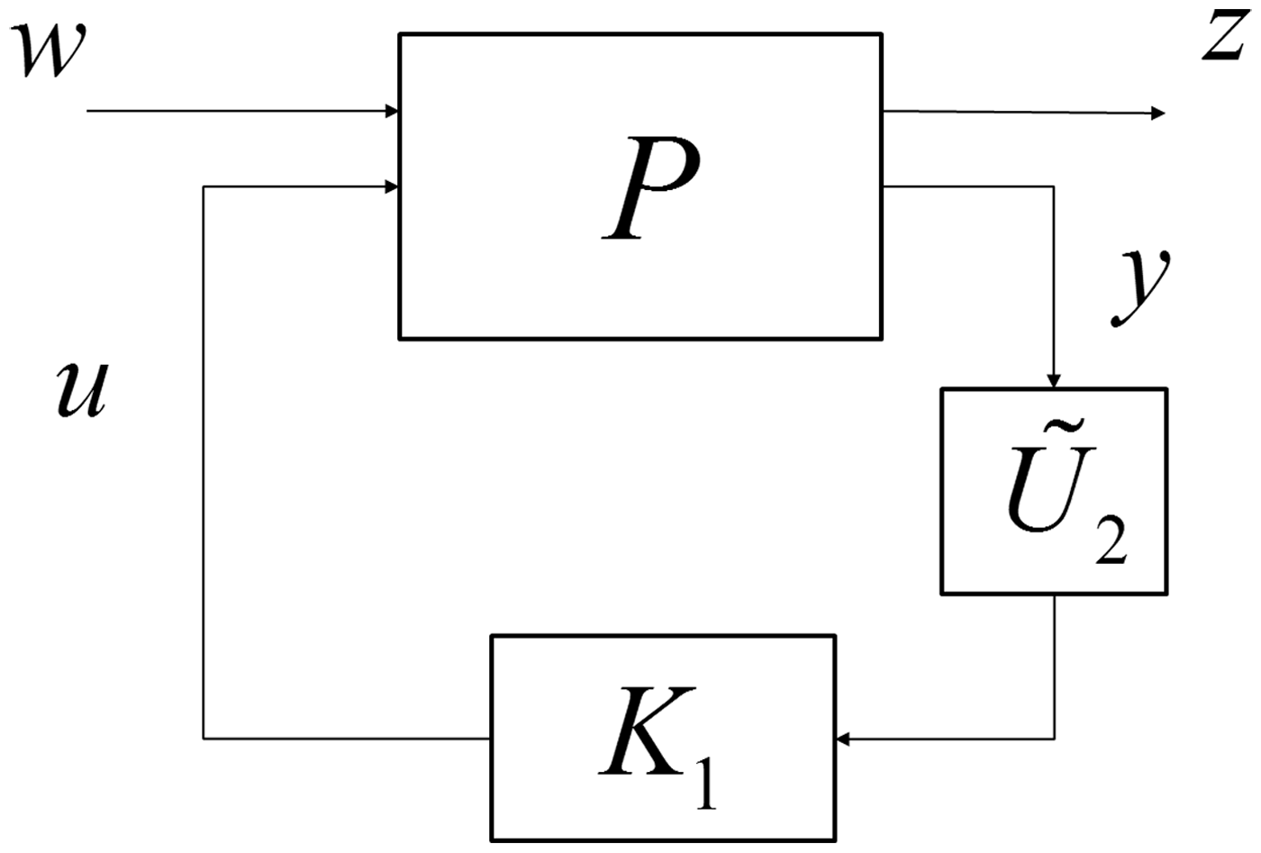
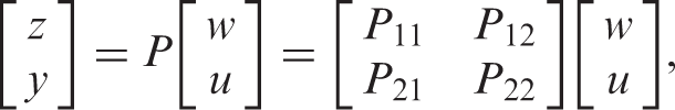
with a characteristic equation of . We can further represent the model as a standard linear fractional transformation (LFT) structure of Figure 3 (Wang et al., 2012a):
where are conformal partition of the plant P, , , u and y are the control and feedback signals, respectively. We can use the following theorem to independently control the system’s responses to the load disturbance Fs and ground disturbance zr.Theorem:(Smith and Wang, 2002; Wang and Smith, 2002)
The LFT structure.
Let P be (open loop) stable, then there exists such that all stabilizing controllers which do not affect can be parameterized as
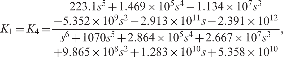
for . Furthermore, K can be expressed as where K1 is a stabilizing controller for .
In our previous studies (Wang et al., 2012a), we set the feedback signals that were measured by one accelerator and one linear variable differential transformer (LVDT), and designed the DRD filter as with
such that the ground disturbances would not activate the control signal; i.e., = 0. Consequently, we can apply soft suspensions to isolate the ground disturbances and then improve the load responses without influencing the ground responses.
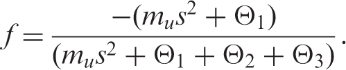
Our design goals now are to isolate the load disturbances by stiff suspensions and then improve the ground responses without influencing the load responses. Therefore, we proposed an inverse DRD filter such that the load disturbances would not activate the control signal; i.e., = 0. At first, we used the same feedback signals as in Smith and Wang (2002) and Wang and Smith (2002): and designed the filter as with
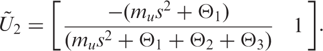
The filter was successfully verified by simulation (Wang et al., 2012b), but failed in experiments because the double integral accumulated errors resulted in saturated control signals. Therefore, we adjusted the feedback signals as (using two LVDTs) or (using two accelerators) to eliminate the double integral term, and designed the following inverse DRD filter:
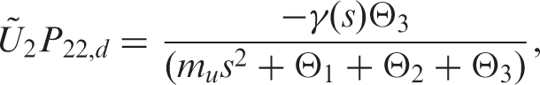
Referring to Figure 3, the plant with feedbacks yd is calculated as
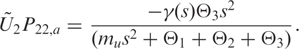
while the plant with feedbacks ya is found as
These plants will be used for robust loop-shaping control design in Section 4.
2.2. The full-table
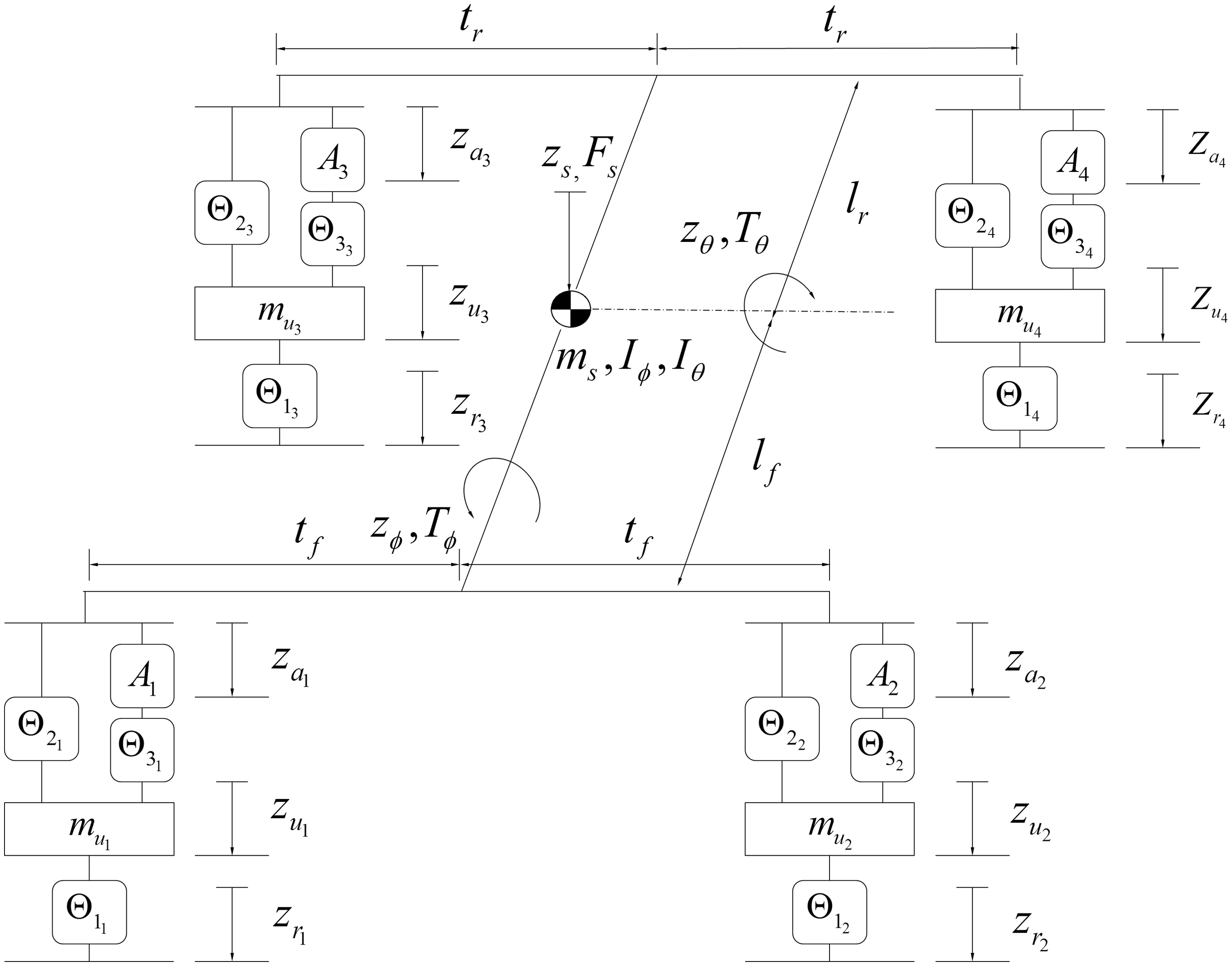
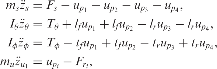
A full-table model, as shown in Figure 4, is now considered. We can further assume that and for for simplification, and describe the model’s dynamics by the following linearized equations:
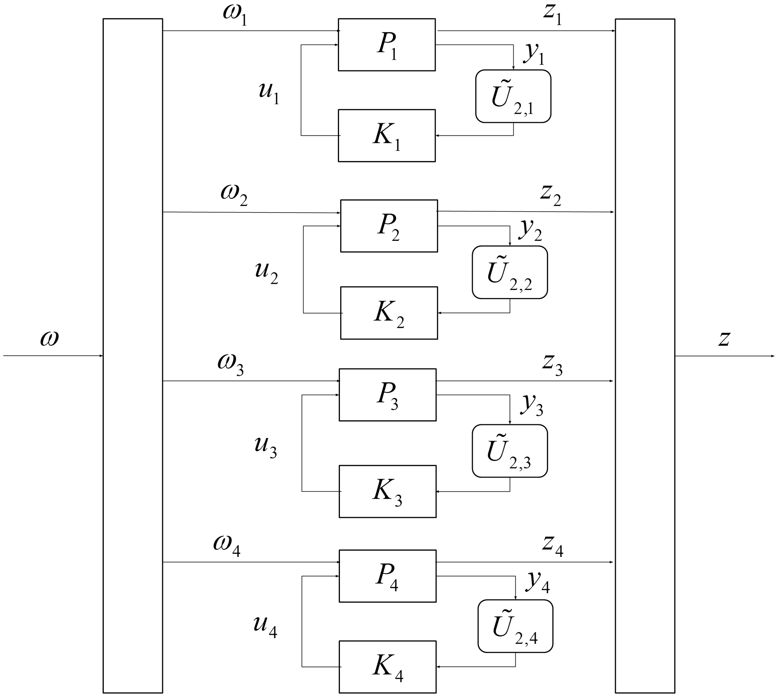
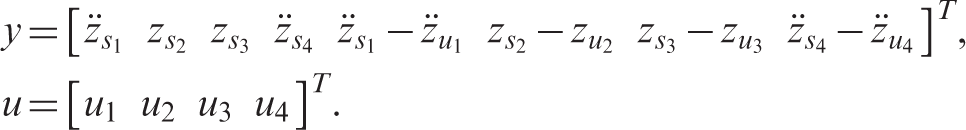
in which and for . Di represents the strut deflections: . is the displacement of the corners; i.e., The control structure can be formulated as Figure 5 with inputs and outputs . We can then consider the full-table model as four quarter-table models with and for . Therefore, we can represent Figure 5 as the standard LFT structure of Figure 3, where P is the full-table model with inputs , outputs , and the following measurements y and control signals u:
The full-table model.
Control scheme for the full-table model.
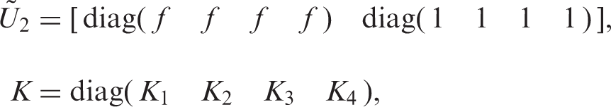
Note that we took acceleration feedbacks at corners 1 and 4, and displacement feedbacks at corners 2 and 3, so that the original four accelerators and four LVDTs can be directly applied for the inverse DRD structure. The corresponding blocks and K are derived as in the following forms:
in which
3. Identification of suspension elements
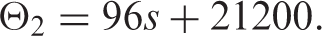
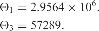
The transfer function of , , and was experimentally identified using the structure of Figure 6. First, Θ was replaced with corresponding passive elements and provided a swept sinusoidal signal zr. Second, zr and zs were measured, and the subspace system identification method was applied (Overschee and Moor, 1994) to derive the transfer functions from zr to zs. The experiments were repeated six times to account for system variation and uncertainties, and the corresponding transfer function was denoted as . Last, we noted that the results varied at each experiment, which might result from system nonlinearities and operating conditions Therefore, we applied the ideas of system gaps (Georgiou and Smith, 1990; Zhou et al., 1996) to decide the transfer functions of the suspension elements. The gap between systems is defined as in the following:Definition:System gap (Georgiou and Smith, 1990)
Identification of the suspension elements.
Suppose a nominal plant G0 has a normalized left coprime factorization of , where and . Assume a perturbed system can be expressed as with , and . The gap between a nominal plant G0 and a perturbed plant is defined as:
The smallest value ofwhich perturbsG0into, is called the gap betweenG0and, and is denoted as.
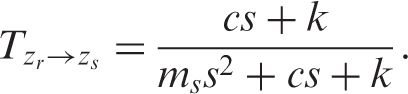
For example, it was assumed that because it is a parallel spring-damper set, and the theoretical transfer function was derived as:
Therefore, for , we calculated the optimal values of c and k which minimized the gap between and as follows:
where is the gap between Gi and . The optimization results gave:
Similarly the following transfer function of and was obtained:
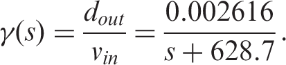
The PZT dynamics was identified by giving a swept sinusoidal voltage input signal and measuring the corresponding displacement output signal , and estimated as:
4. Active controller design
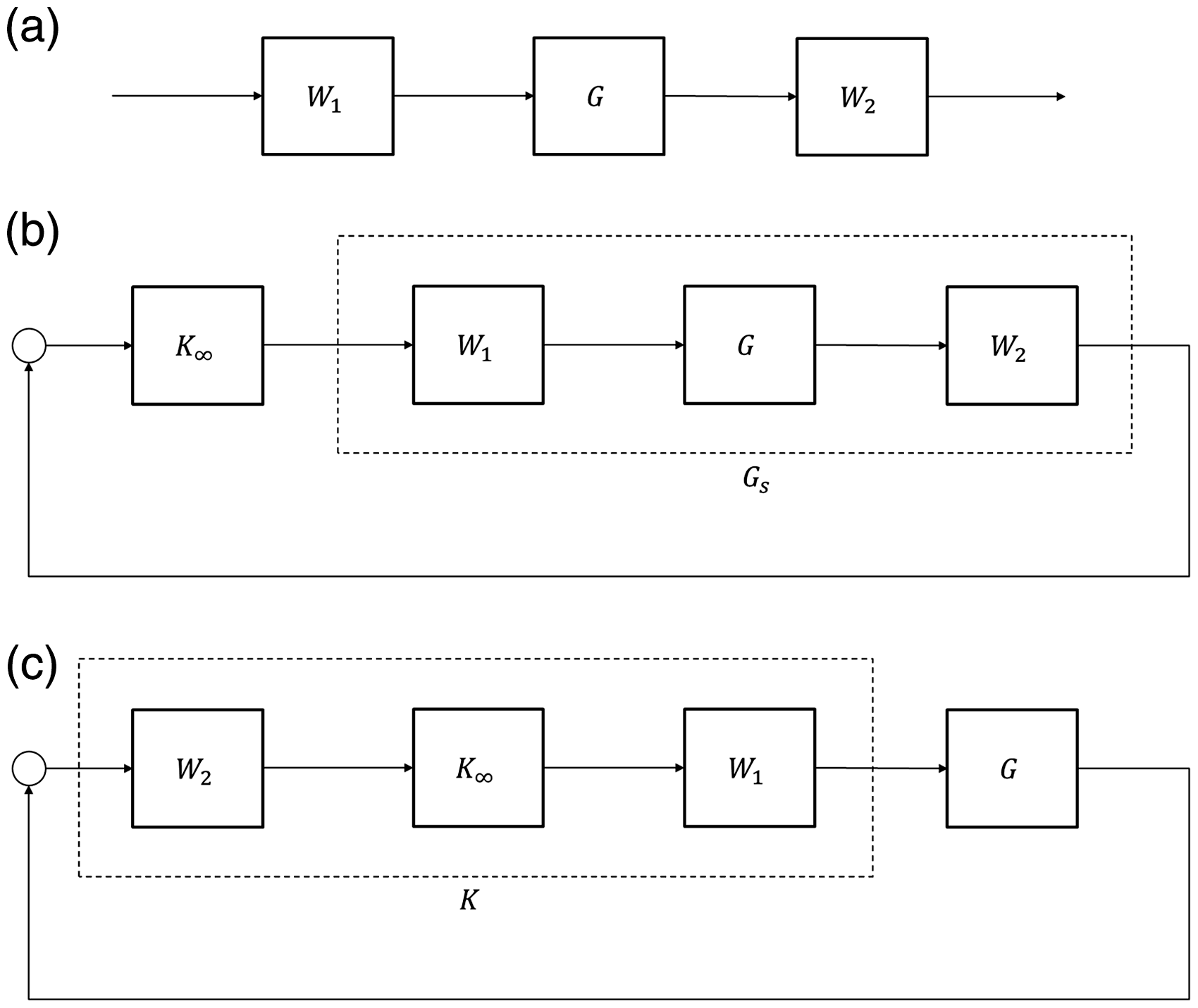
In this section, we apply loop shaping techniques (Zhou et al., 1996) to design the actuator controllers to improve the system’s ground disturbances. The loop shaping design procedures can be summarized as follows (see Figure 7): (a) Selecting suitable weighting functions W1 and W2 to form a weighted plant ; (b) Designing a controller that stabilizes the shaped plant Gs; (c) Implementing the shaped controller to the original plant G.
Loop shaping design.
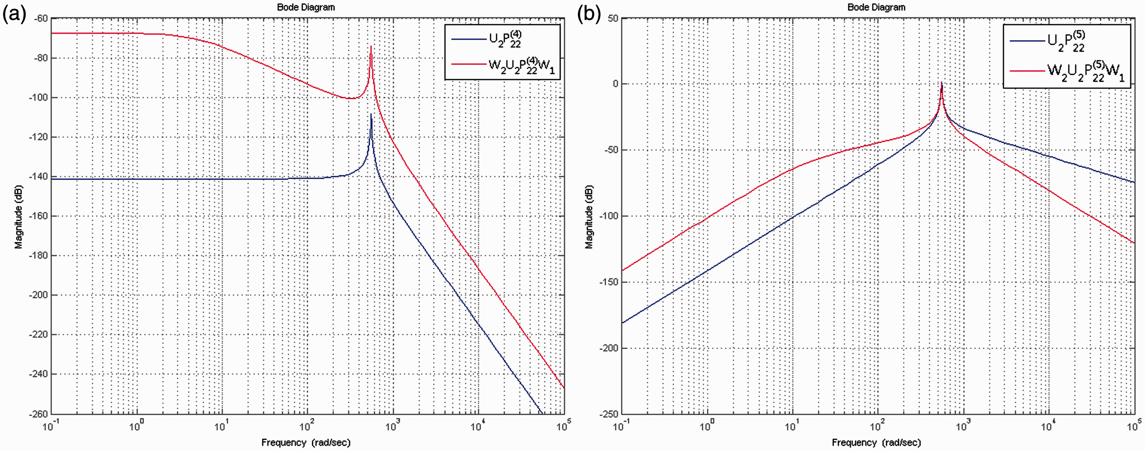
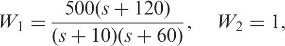
The weighting functions are normally selected to provide high system gains at the low-frequency ranges for disturbance rejection, and low system gains at the high-frequency ranges to attenuate noises. Because the ground disturbances are normally human- or traffic-induced within certain frequency ranges; e.g., between 0.8 and 10 Hz (Mhanna et al., 2012), we can use the weighting functions to improve the ground responses at these frequency ranges. We iteratively adjusted the weighting functions and verified them by experiments. First, we considered the plant of (4) with displacement feedback, and selected the following weighting functions:
The Bode plots of the original and weighted plants are shown in Figure 8(a), where we raised the low frequency gains for isolating the ground disturbances. The robust controllers were designed as
with a stability margin (McFarlane and Glover, 1990) If the stability margin is greater than the system gaps, the designed controller can guarantee internal stability for all perturbed models. Therefore, we further analyzed the system gaps of (4) with the values of identified in Section 3. First, for each we obtained six values of from the experiments, and combined them as models: for . Second, we calculated the maximum system gap between these models and the nominal model as . Because the stability margin is much greater than the system gaps, the stability of the closed-loop system can be guaranteed.
Bode plots of original plants and shaped plants.
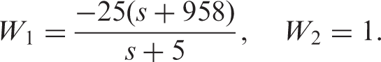
Similarly, we considered the plant of (5) with acceleration feedback, and chose the following weighting functions:
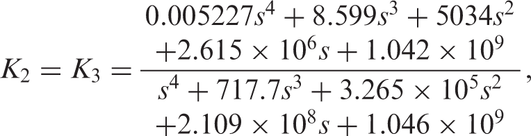
with the Bode plots of Figure 8(b), where we increased the low-frequency gains to suppress the ground disturbances. The robust controllers were designed as:
which gives a stability margin of We composed 216 models for , with the values of obtained from the experiments. Then we calculated the maximum gap between these models and the nominal model as .
Because the system gap is less than the stability margin, the designed controller can guarantee closed-loop stability. Finally, the shaped controllers were implemented for performance verification.
5. Experimental results
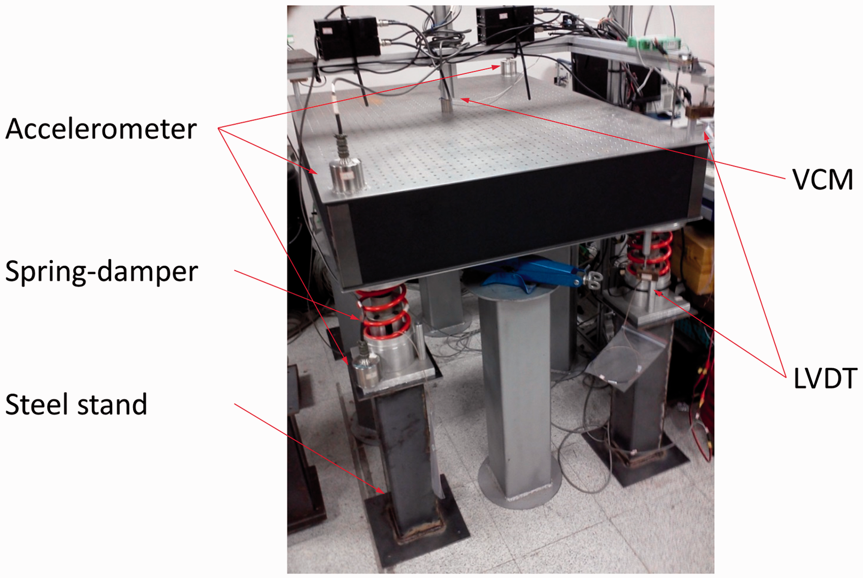
In this section, we implement the inverse DRD structure and the designed robust controllers for experimental verification. The experimental layouts are shown in Figure 9, where we generated the disturbances by voice coil motors (VCMs) and measured acceleration and displacement signals for feedback.
The full table system.
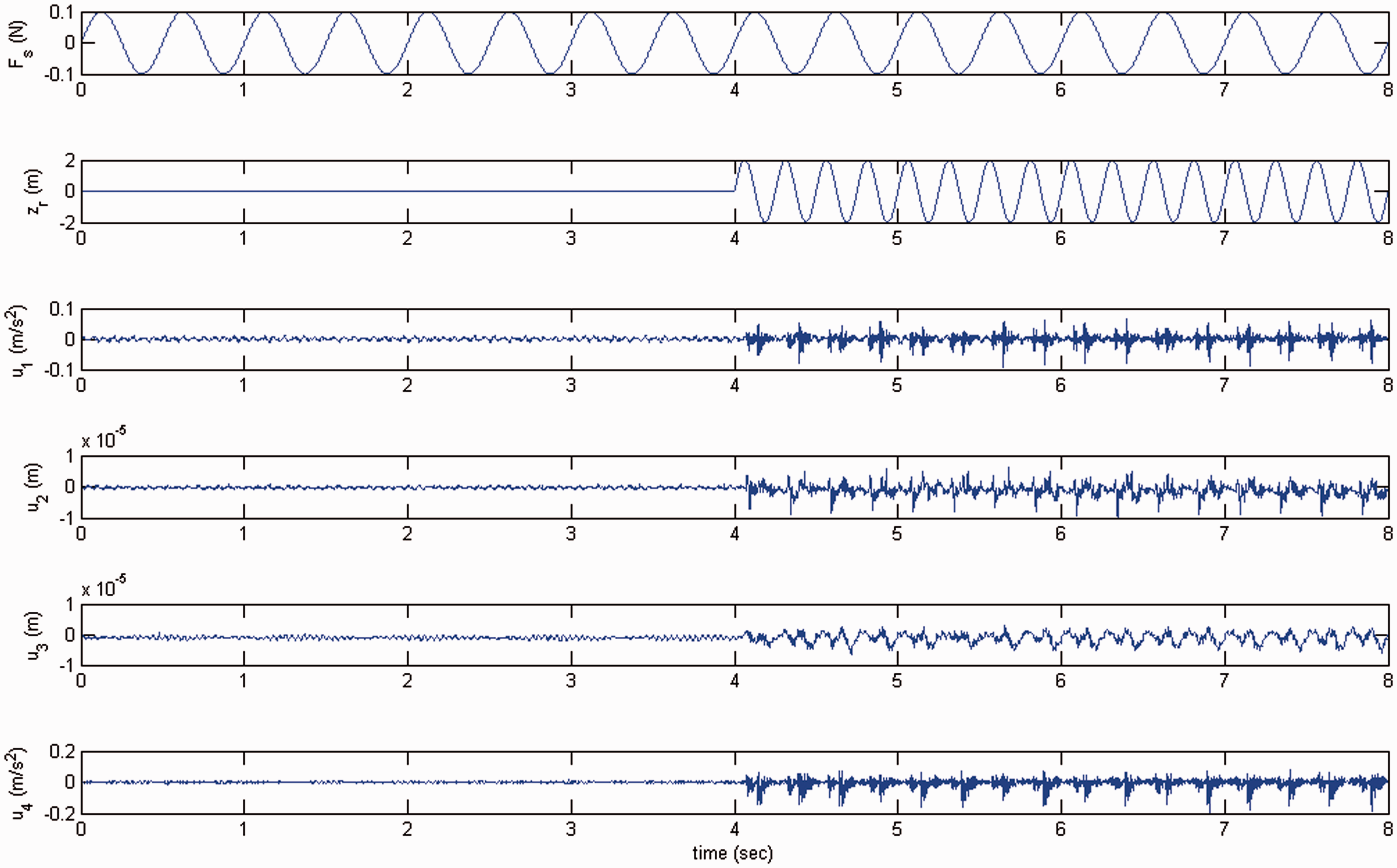
First, we applied VCMs to generate load disturbances Fs and ground disturbances , and took acceleration feedbacks at corners 1 and 4, and displacement feedbacks at corners 2 and 3 to calculate the control signals . The disturbances and corresponding PZT control signals are shown in Figure 10. We note that the control signals were not activated by the load disturbances; i.e., the inverse DRD structure was effective. Furthermore, the control signals were bounded; i.e., the closed-loop system was stable using the designed controllers, as analyzed in Section 4. Therefore, we can use stiff passive elements to attenuate load disturbances and apply active control to improve the system’s ground disturbances.
The inverse DRD effects.
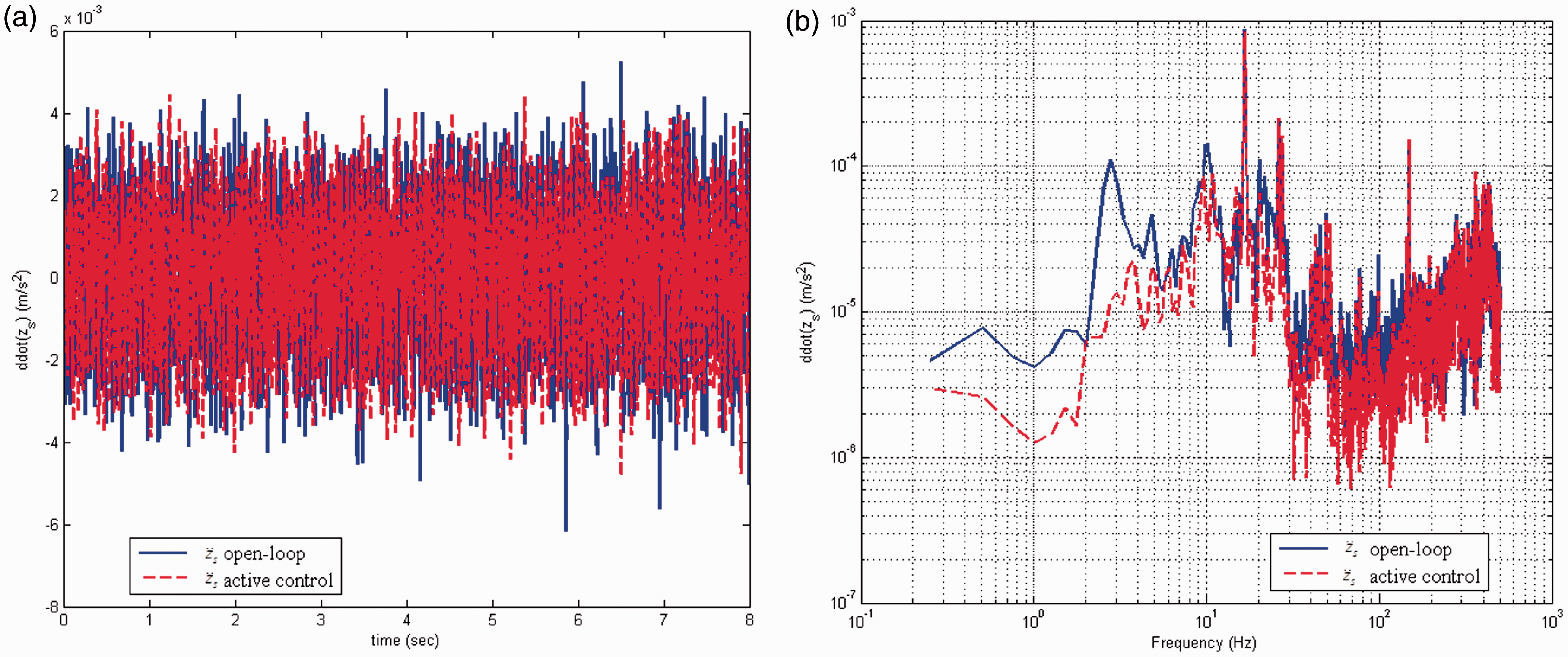
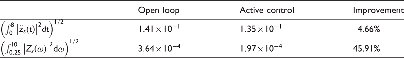
Second, we applied a VCM to generate white-noise ground disturbances to demonstrate the vibration suppression by the designed robust loop shaping controllers. The experimental time responses are illustrated in Figure 11(a), where the magnitude was slightly reduced by the designed active controllers. To further appreciate robust loop-shaping control, we took fast Fourier transform of the measured data and denoted it as . The results are shown in Figure 11(b), where the frequency responses at the concerned frequency ranges were significantly suppressed by the loop-shaping design. The statistic data of Figure 11 is illustrated in Table 1, where the time responses were decreased by 4.7%, while the frequency responses at the concerned frequency ranges were greatly improved by 45.9%. This means that, in the future, we can apply the loop-shaping techniques to improve system performance at particular frequency ranges.
Improvement of ground responses by active control. (a) Time-domain. (b) Frequency-domain.
This paper has applied an inverse DRD structure to control vibration for an optical table. First, we developed a double-layer structure and used stiff suspensions to isolate load disturbances. Second, we derived an inverse DRD filter such that the actuator should improve the system’s ground responses without influencing the satisfied load responses. Third, we designed robust loop-shaping controllers that can improve system performance to ground disturbances at particular frequency ranges. Lastly, the designed inverse DRD structure and robust controllers were implemented for experimental verification. The results show that the proposed design was deemed effective.
Footnotes
Acknowledgments
The authors would like to thank Mr. Yu-Chuan Chen for help in the stability analysis of the revision.
Funding
This work was supported in part by the National Science Council of Taiwan under grant number 102-2221-E-002-150.
References
1.
ChangPHHanDKShinYHKimKJ (2010) Effective suppression of pneumatic vibration isolators by using input-output linearization and time delay control. Journal of Sound and Vibration329(10): 1632–1652.
2.
GeorgiouTTSmithMC (1990) Optimal robustness in the gap metric. IEEE Transactions on Automatic Control35(6): 673–686.
3.
KatoTKawashimaKFunakiTTadanoKKagawaT (2010) A new, high precision, quick response pressure regulator for active control of pneumatic vibraiotn isolation tables. Precision Engineering34(1): 43–48.
MhannaMSadekMShahrourI (2012) Numerical modeling of traffic-induced ground vibration. Computers and Geotechnics39: 116–123.
6.
OhJSHanYMChoiSBNguyenVQMoonSJ (2012) Design of a one-chip board microcontrol unit for active vibration control of a naval ship mounting system. Smart Materials and Structures21(8): 087001.
7.
OverscheePVMoorBD (1994) N4SID-subspace algorithms for the identification of combined deterministic-stochastic system. Automatica30(1): 75–93.
8.
SmithMCWangFC (2002) Controller parametrisation for disturbance response decoupling: application to vehicle active suspension control. IEEE Transactions on Control Systems Technology10(3): 393–407.
WangFCSmithMC (2002) Disturbance response decoupling and achievable performance with application to vehicle active suspension. International Journal of Control75(12): 946–953.
11.
WangFCYuCHTsai JeffTHYangSH (2012a) Decoupled robust vibration control of an optical table. Journal of Vibration and Control20(1): 38–50.
12.
Wang FC, Yang SH and Wu SY (2012b) Inverse disturbance response decoupling control of an optical table. In: Proceedings of the SICE Annual Conference. Akita University, Akita, Japan, 20–23 August 2012, pp. 2226–2231.
13.
ZhouKDoyleJCGloverK (1996) Robust and Optimal Control, New Jersey: Prentice Hall.