
Abstract
In hybrid damper systems active control devices are usually introduced to enhance the performance of otherwise passive dampers. In the present paper a hybrid damper concept is comprised of a passive viscous damper placed in series with an active actuator and a force sensor. The actuator motion is controlled by a filtered integral force feedback strategy, where the main feature is the filter, which is designed to render a damper force that in a phase-plane representation operates in front of the corresponding damper velocity. It is demonstrated that in the specific parameter regime where the damper force leads velocity the control is stable and yields a significant improvement in damping performance compared to the pure viscous damper.
1. Introduction
Supplemental passive dampers (Fu and Kazai, 1998; Sorace and Terenzi, 2008) and base-isolation systems (Snowdon, 1979) are used in many aspects of structural engineering for mitigation of excessive dynamic response (Symans et al., 2008). However, improved damping performance compared to the passive case may be obtained by combining pure energy-dissipating installations with active elements to form so-called active/passive or hybrid damper systems (Thenozhi and Yu, 2013). Hybrid systems have been proposed for base-isolation (Beard et al., 1994; Xiong et al., 2000; Shin et al., 2013) and seismic protection systems (Tzan and Pantelides, 1994; Sener and Utku, 1998; Kurata et al., 1999; Kim and Adeli, 2005). In these systems the ‘passive’ properties of the system are often governed by basic load-carrying requirements and thereby appear nonoptimal with respect to the transmissibility problem. Thus, the augmentation to hybrid form allows the base-isolation system to maintain its structural integrity, while enhancing the isolation properties by suitable control of the additional active member. Hybrid damper forms have also been suggested in so-called active tuned mass dampers (Lee-Glauser et al., 1997; Mitchell et al., 2012) or active vibration absorbers (Kwak et al., 2002; Tso et al., 2012), where the aim of the active control unit may be to improve the performance of the absorber with respect to transient response during for example an earthquake, reduce the absorber mass without loss of performance or simply increase the operational bandwidth of the absorber. Finally, hybrid control has also been considered in damping layer treatment of beams and plates, where the damping efficiency of passive energy-dissipating (constrained) layers is improved effectively by the incorporation of active piezoelectric elements (Benjeddou, 2001; Trindade and Benjeddou, 2002; Trindade, 2011).
In the present paper a pure viscous dashpot is placed in series with both an active actuator and a force sensor, where the actuator motion is controlled by a decentralized collocated control algorithm based on feedback from the force sensor. The force feedback concept has been effectively used in space structure applications, where Preumont and coworkers have successfully implemented integral force feedback (IFF) for piezoelectric vibration control of truss structures (Preumont et al., 1992, 2008) and in active tendon control (Preumont and Achkire, 1997). In piezoelectric vibration control the transducer is conveniently placed in series with the force sensor, whereby the force measurement indirectly represents the displacement signal through the elastic properties of the piezoelectric transducer. Thus, the integration of the force provides a signal in phase with the energy-conjugated velocity, whereby damping is obtained by IFF. A thorough introduction to the IFF control approach and the corresponding implementation aspects can be found in the book by Preumont (2011). Alternative feedback strategies suitable for, in particular, piezoelectric vibration control have been proposed by Chen and Lurie (1992) and Kanestrøm and Egeland (1995), while Hyde and Anderson (1996) consider the application of force feedback control together with a (viscous) voice coil element instead of a piezoelectric transducer. In the case of active tendon control Guo et al. (2008, 2012) have proposed various modifications of the IFF control by Preumont and Achkire (1997). In Guo et al. (2008) a proportional-integral (PI) control format is introduced, while recently in Guo et al. (2012) a filtered IFF format results in a stable format which introduces a dissipative viscous component together with a proportional term, representing positive control stiffness. Furthermore, in Smrz et al. (2011) the IFF approach has been modified to give the so-called beta-controller, which is able to effectively introduce damping to the structure and maintain the static stiffness of the active tendons.
The aim of the present paper is to formulate a robust and effective control strategy, where the actuator motion is controlled by a filtered integration of the force feedback signal from the force sensor. Because the actuator is placed in series with the dissipative viscous dashpot the purpose of the control is to alter the apparent characteristics of the combined device so that larger damping ratios are obtained for the flexible structure, compared to the pure viscous case without active control. The hybrid damper concept is presented in Section 2, which also proposes a calibration of the filter constant. The robustness and performance of the hybrid damper concept are then demonstrated in Section 3, where stability limits are derived in Section 3.1, while the damping efficiency is subsequently assessed in Sections 3.2 to 3.4 by a root locus, a frequency response and a time transient analysis, respectively. It is shown that for an appropriately filtered force signal the feedback control of the hybrid concept yields a significantly more effective damper system than the passive viscous damper. The results are summarized in Section 4, which also addresses some aspects concerning the possible implementation of the control, and identifies some main limitations and drawbacks of the hybrid viscous damper.
2. The hybrid damper concept
The hybrid damper concept is illustrated in Figure 1. It is composed of a viscous dashpot with coefficient c in series with a load cell which measures the damper force f(t) and an active actuator or strut with stroke or piston motion q(t). In structural engineering applications servo-hydraulic actuators are often used to realize active control strategies, and as demonstrated by Gao and Dyke (2014) the desired actuator motion q(t) may effectively be tracked by a simple proportional-integral-derivative (PID) approach. Furthermore, the experimental setup in Gao and Dyke (2014) combines an actuator placed in series with a load cell and a spring, and is therefore similar to the hybrid damper shown in Figure 1(b), which contains a viscous dashpot instead of an elastic spring.
(a) Flexible structure with (b) hybrid damper concept.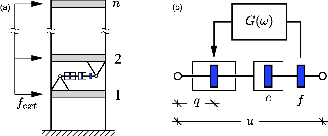
2.1. Filtered IFF
The motion of the hybrid damper is denoted u(t), which means that the velocity over the viscous dashpot is

2.2. Frequency domain analysis
The characteristics of the hybrid damper are investigated in the frequency domain by assuming the complex harmonic solution forms
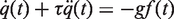
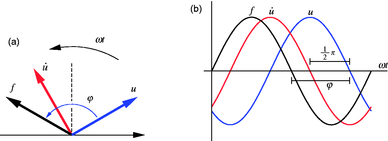
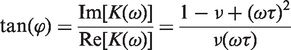
(a) Magnitude and (b) phase of the stiffness modulus (a) Phase-plane vector diagram and (b) response of hybrid damper displacement, velocity and force.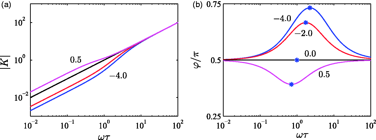

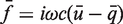

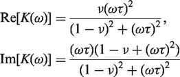

As explained previously equation (2) recovers the IFF control format in the limit τ = 0. It follows from (7) that in this limit the damper force relation reduces to
3. Damping of a flexible structure
As shown in Figure 1, in the present paper it is assumed that a single hybrid viscous damper acts on a flexible structure, represented by a discrete numerical model. The equations of motion for the structural degrees of freedom in the vector

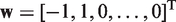
In the remaining part the performance and properties of the hybrid viscous damper are illustrated with respect to damping of flexible structures. It is therefore convenient to eliminate the damper force f(t) in both (14) and (2) by the viscous relation (1), whereby the governing closed-loop equations can be written in compact matrix form:
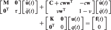
Next, the stability conditions for the filtered IFF control are derived, whereafter the damping performance is investigated by a root locus, a frequency response and finally a time transient analysis.
3.1. Closed-loop stability
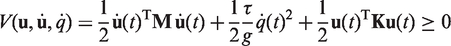
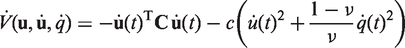
The stability of the control is analyzed for the closed-loop system of equations in (15) with external load vector
3.1.1. Positive gain
First consider the case with g > 0, whereby
3.1.2. Negative gain
Now consider the case with g < 0, whereby
3.2. Root locus analysis
The damping performance of the hybrid damper concept is initially illustrated by a root locus analysis with respect to increasing viscous coefficient c and fixed values of ν and τ. Thus, for a particular locus in the complex plane with constant ν the control gain g is inversely proportional to the increasing viscous parameter c via the relation (8). The equations of motion in (15), with external load vector
Figure 4(a) shows the four root loci for the first vibration mode of the 10-storey shear frame structure with (a) Root locus plot and (b) damping ratio for increasing c, with 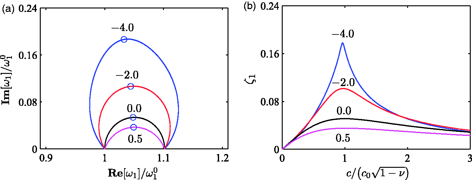
Figure 4(b) shows the corresponding modal damping ratio ζ1, evaluated as the relative imaginary part of the natural frequency,

The complex-valued mode shapes for the first vibration form of the shear frame structure are shown in Figure 5. The mode shapes are determined for the maximum damping case, represented by the circles in the root locus diagram in Figure 4(a), and normalized to unity at the top floor. The blue curves with asterisks represent the real parts of the mode shape vector, while the magenta curves with circles represent the corresponding imaginary parts. The additional black curves represent the undamped mode shape. Figure 5(a) shows the passive viscous case with ν = 0, and it is seen that the change in mode shape relative to the undamped case is only moderate. When increasing the magnitude of Real (blue *) and imaginary (magenta 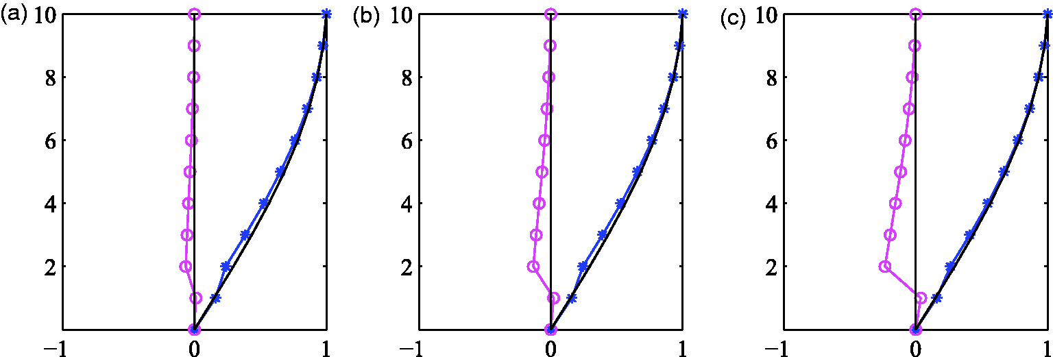
3.3. Frequency response analysis
The root locus analysis of the previous section represents the idealized case of free vibrations, without any modal interaction. This means that for realistic response and/or loading conditions the attainable damping determined from the root locus analysis may not be entirely realizable. Therefore, forced response characteristics are now considered in terms of a frequency response analysis, where harmonic motion is assumed by the complex representations

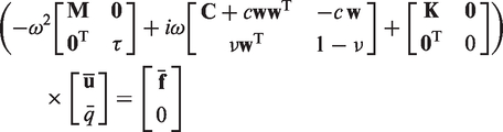
Figure 6 shows the frequency-dependent amplitudes for the harmonic response of both the structure and the hybrid damper, obtained from (23). The three curves in Figure 6 represent (a) Top floor and (b) hybrid damper response, (c) actuator displacement and (d) force with 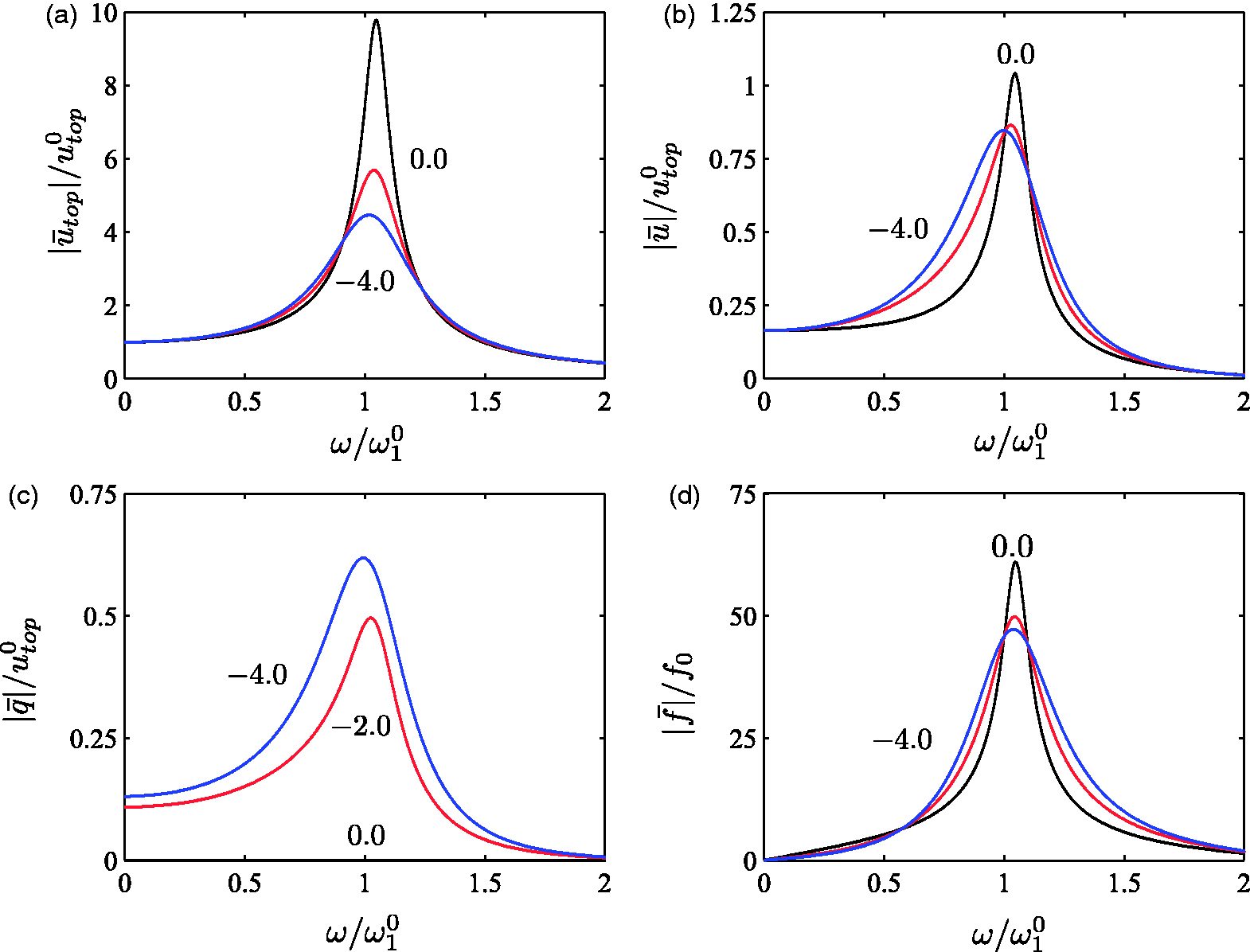
The hybrid damper concept is effective for the targeted vibration mode and the response mitigation improves with increasing magnitudes of Top-floor response of (a) second and (b) third vibration modes with 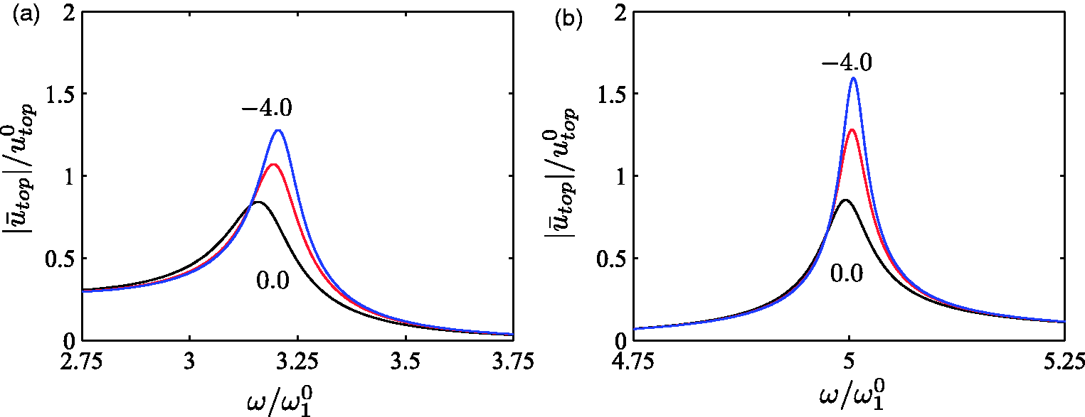
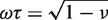
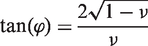
The maximum phase angle of the filtered IFF control is identified by the asterisks in Figure 2(b), and the corresponding time scale is governed by the relation (12) and therefore determined to be Top-floor response with (a) 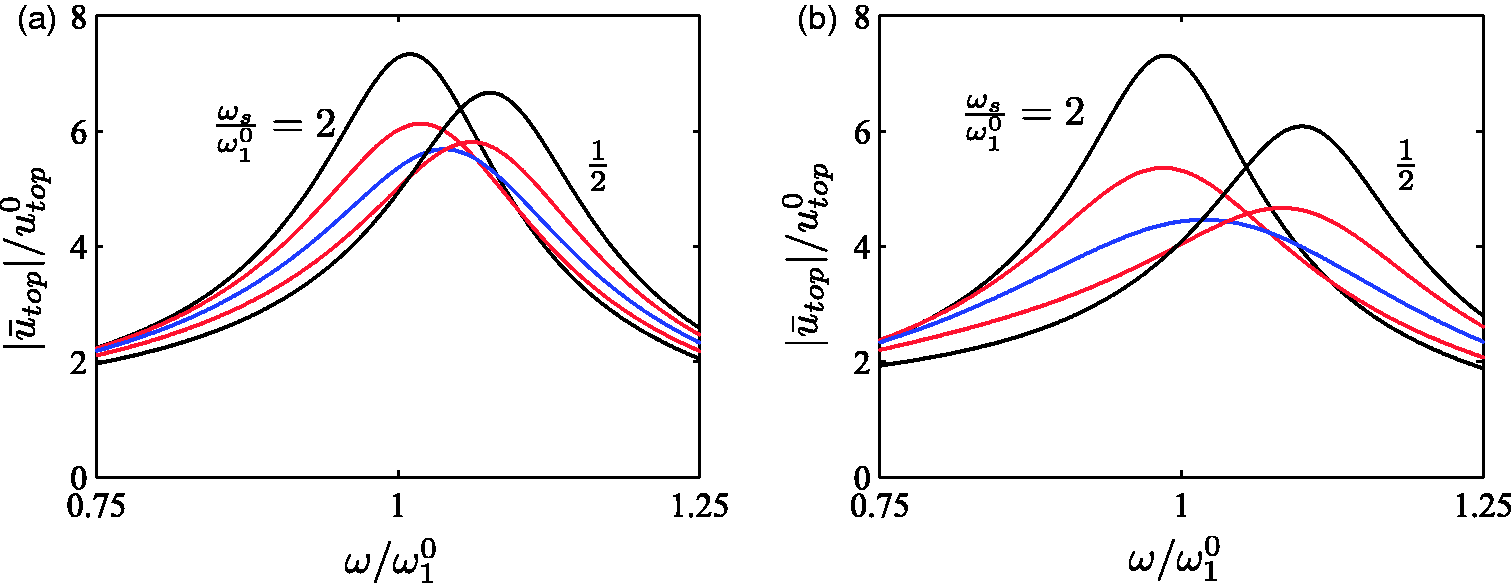
3.4. Time-dependent analysis
This section considers a transient vibration analysis of the shear frame structure in Figure 1, where the hybrid damper is again located between the first floor and the second floor. The governing system equations are given in (15), and as in the root locus and frequency response analysis structural damping is omitted (
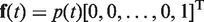
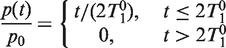
In this transient analysis the shear frame structure is loaded locally at the top floor by a linearly increasing force, which is then removed instantaneously after two vibration periods. The time-dependent external load vector is given as
The time histories of the structural and hybrid damper response are shown in Figure 9, where the three curves in each sub-figure again represent (a) Top floor and (b) hybrid damper response, (c) actuator displacement and (d) damper force with 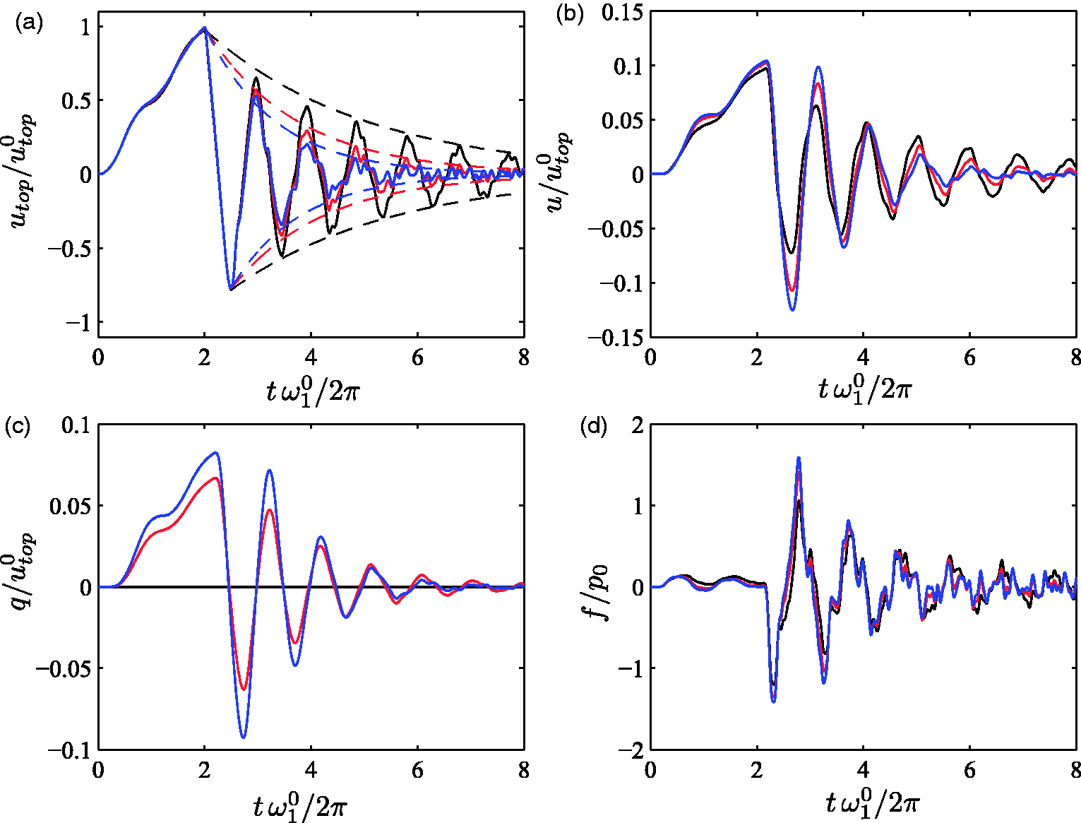
The time histories of the top-floor response utop are shown in Figure 9(a). The curves are normalized by the corresponding static top-floor deflection
The damper response u(t) is shown in Figure 9(b). For the passive viscous case with ν = 0 the damper motion exhibits a monotonically decaying amplitude envelope. For the active cases with
In general, Figure 9(b) to (d) shows that the magnitude of the initial transient damper response increases with the magnitude of ν, which is just opposite of what has been concluded for the harmonic analysis in connection with Figure 6, where the damper amplitudes
4. Summary
The hybrid damper is composed of a viscous dashpot in series with an active actuator and a load cell. A main contribution of the present research is the formulation of a suitably filtered IFF control of the actuator motion, which produces a damper force component that operates ahead of the energy-conjugated velocity in a phase-plane vector representation and thereby introduces improved damping performance as compared to the passive viscous benchmark damper. The phase lead of the damper force is the key ingredient in the present control format, and as demonstrated in connection with Figure 2(b) maximum phase lead is obtained by the relation in (12). Thus, the filter is effectively calibrated by

Footnotes
Funding
This work has been supported by the Danish Energy Agency and Vestas Wind Systems A/S under the EUDP project ‘Monopile cost reduction and demonstration by joint applied research’.