
Abstract
In this paper, a study on a doubly clamped microresonator actuated by two symmetrical electrodes is carried out to investigate its dynamic properties with delayed velocity feedback control. A stability chart of the linearized system depicting delay time versus feedback gain is drawn first, which is actually nonperiodic. Moreover, stability switches do exist in this system. Then, the method of multiple scales is used to determine the existence, stability and dynamic properties of small amplitude vibration in the neighborhood of different equilibrium positions. It is shown that the stability condition via perturbation analysis overestimates the system stable region. The delayed stability condition via linearized analysis is more suitable for stability estimation. The following analytical and numerical results are presented to investigate frequency responses and frequency/damping trimming properties with various system and control parameters. Moreover, explicit formulas for optimum direct current (DC) voltage and equivalent natural frequency, corresponding to an approximate linear-like state, are deduced, respectively. Two typical design sketches depicting the initial gap width versus DC voltage are drawn with different beam lengths and thicknesses. Finally, a case study is carried out to verify the correctness of our analytical results about linear-like state prediction and frequency/damping trimming.
Keywords
1. Introduction
Recently, micro-electro-mechanical systems (MEMSs) have been developed for various applications in the field of sensing and actuating (Batra et al., 2007; Nayfeh et al., 2010; Younis, 2011; Zhang et al., 2014). As one core micro-component of the MEMS community, electrically actuated microbeams have attracted much attention and have been investigated by many scholars. Their concentrations mainly focus on the static or dynamic properties of microbeams, such as pull-in instability (Nayfeh et al., 2007; Krylov et al, 2008, Fang and Li, 2013), nonlinear characteristics (Luo and Wang, 2002; Haghighi and Markazi, 2010; Towfighian et al., 2011; Zaitsev et al., 2012; Chen et al., 2013; Younesian et al., 2014; Han et al., 2015a), control strategies (Park et al., 2008; Haghighi and Markazi, 2010; Lakrad and Belhaq, 2010; Song and Sun, 2013; Rahim and Younis, 2016) and some design analyses (Hu et al., 2004; Kouravand, 2011; Seleim et al., 2012; Han et al., 2015b). In this paper, based on our previous works (Han et al., 2015a, 2015b), an extended study on a doubly clamped microresonator actuated by two symmetrical electrodes (Haghighi and Markazi, 2010) is carried out to investigate its stability and dynamic properties with delayed velocity feedback control.
The delayed feedback signal can be displacement, velocity and acceleration (Shao et al., 2013). Generally, feedback controllers have the ability to stabilize the system response and enhance resonator performance (Hu and Wang, 2002). For instance, Ge and Lin (2003) used delayed displacement feedback control to effectively suppress the chaos of an electro-mechanical gyrostat system. Yamasue and Hikihara (2006) presented a delayed displacement feedback controller to stabilize the chaotic motion of micro-cantilevers in dynamic force microscopy and showed the experimental stabilization results in their subsequent study (Yamasue et al., 2009). Alsaleem and Younis (2010, 2011) used a delayed velocity/displacement feedback controller to effectively enhance the stability of microresonators driven electrostatically in a nonlinear regime and prevent them from pull-in instability. Rezaie and Jahed Motlagh (2011) addressed a new adaptive delayed displacement feedback controller to stabilize a class of chaotic time-delayed systems with a variable parameter. Nayfeh and Nayfeh (2012) proposed a delayed acceleration feedback control strategy to mitigate regenerative chatter in turning on lathes. Recently, by the application of the finite difference technique combined with Floquet theory, Masri et al. (2015) investigated the stabilization effect of a delayed velocity feedback controller for MEMS resonators undergoing large motion.
However, delayed feedback controllers with inappropriate control parameters may also deteriorate the control performance or even lead to unstable responses of systems (Hu and Wang, 1998; Hu et al., 1998). Thus, the effects of delayed feedback control on system performances still need to be considered. Wang et al. (2004b) studied the local dynamics of a one-degree-of-freedom (1-DOF) system with delayed velocity feedback and pointed out that feedback control could induce Hopf bifurcation. Global dynamics of a Duffing oscillator with delayed displacement feedback were also studied by Wang et al. (2004a). Stability switches and local bifurcations were presented and analyzed in detail. Sun et al. (2006, 2007) investigated the control mechanism of delayed displacement and velocity feedback control on a nonautonomous Duffing oscillator. The results showed that positive feedback could reduce the possibility of chaos, while negative feedback could enlarge the possible chaotic domain. El-Bassiouny (2006) presented an analysis of primary and subharmonic resonances of a cantilever beam under delayed displacement and velocity feedback control. Using the method of multiple scales (MMS), the effect of time delay was investigated and the equivalent damping concept related to delay feedback was proposed in his study. Xu et al. (2007) proposed a perturbation incremental scheme to study the delayed displacement feedback control on double Hopf bifurcation and nonlinear dynamics of a general dynamic system. Naik and Singru (2011) presented the resonance, stability and chaotic analyses of a quarter-car vehicle system with delayed displacement and velocity feedback, and pointed out the importance of feedback control on system performance, which should be taken into account for designing vehicle suspension systems. Siewe et al. (2012) presented a study on the Rayleigh–Duffing oscillator with delayed displacement and velocity feedback signals and found that appropriate choice of time delay could broaden the stable region of the nontrivial steady-state solutions and enhance control performance. Shao et al. (2013) used the MMS to investigate the small vibration of a microresonator with delayed velocity feedback control, and pointed out that positive feedback control could strengthen system stability, while negative feedback could lead to an unstable response.
From the above analyses, one can see that delayed feedback controllers are very important to the stability and response of dynamic systems. Analytical investigations are required to reveal the control mechanism and obtain appropriate control regions. In Shao et al. (2013), the effect of delayed velocity feedback control on a microresonator actuated by one electrode was investigated in detail. The function of the controller on system damping trimming was discussed analytically and numerically. Their work sheds light on the theoretical analysis of dynamic a MEMS with delayed feedback control. However, they only considered a fixed delay time (half period of free oscillation) and then realized system damping control. Detailed operation mechanisms of this type of controller on the microresonator with other delay times are still unclear. Furthermore, our early studies find that the stable region is actually nonperiodic and stability switches do exist in this system, which is different from the periodic stability conclusion described by Shao et al. (2013). Moreover, with the decrease of characteristic size in MEMSs, it seems to be feasible to obtain velocity signals of the microbeam through an extra electrode (Mestrom et al., 2008, 2009). All of the above motivate our present work.
The rest of this paper is organized as follows. In Section 2, an analytical model with delayed velocity feedback control is briefly introduced. The equilibrium positions of its Hamiltonian system are given based on our previous works (Han et al., 2015a, 2015b). In Section 3, the effect of delayed feedback control on system stability is carried out via linearization analysis. A stability chart induced by the delayed velocity feedback controller is investigated in detail. Then, the MMS is applied to determine the response and stability of small vibration around different equilibrium positions. In Section 4, analytical and numerical results are given to investigate the frequency responses and frequency/damping trimming properties with different system and control parameters. Some design tips on linear-like state and frequency/damping trimming are discussed and then numerically verified. Finally, the last section presents the discussion and conclusions.
2. Model description
A simplified 1-DOF model to describe an electrostatically actuated microresonator (Haghighi and Markazi, 2010) is shown in Figure 1, in which Schematic of an electrostatically actuated microresonator with delayed velocity feedback control.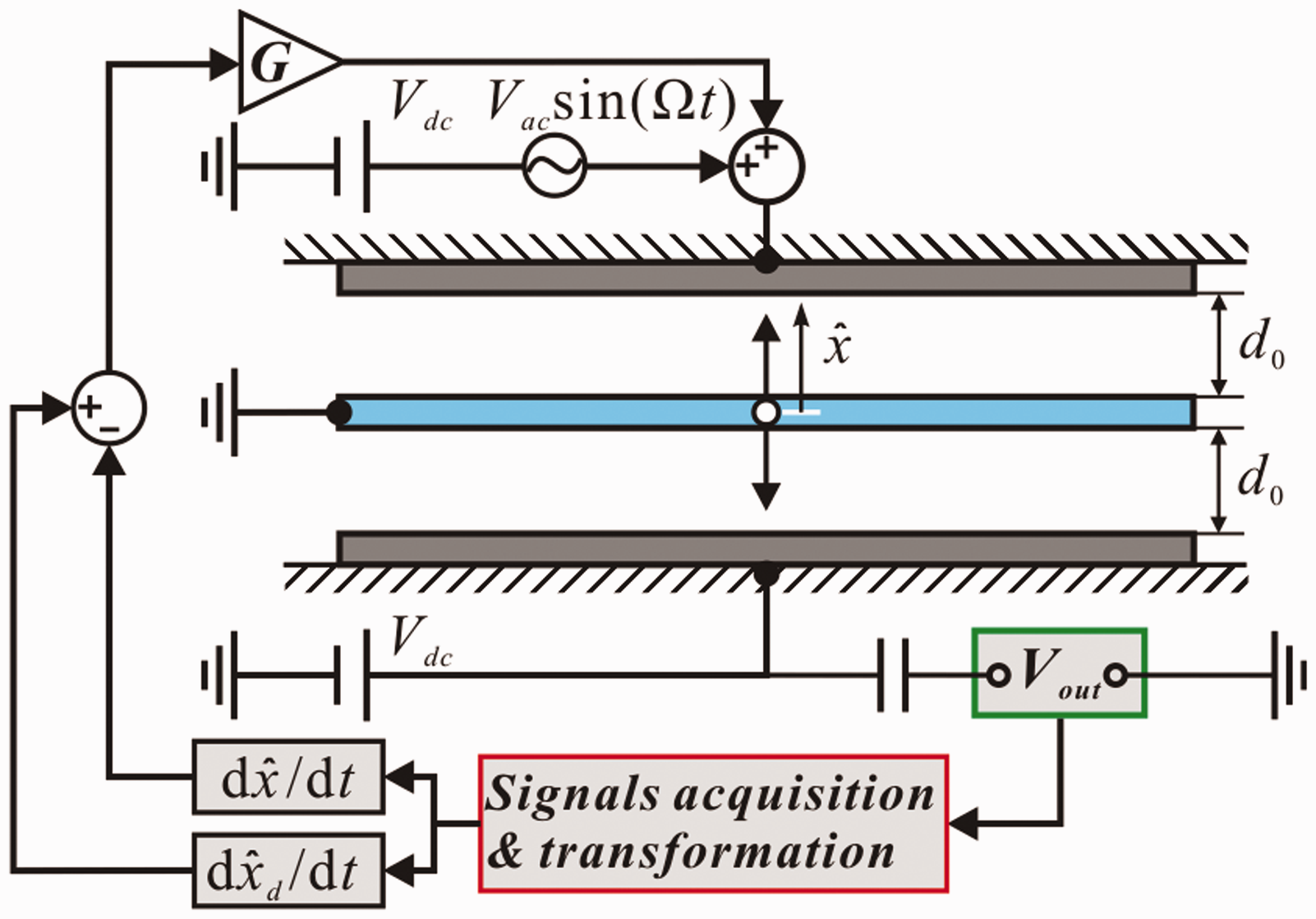
In fact, the actuation voltage and feedback signals can be designed and applied from either side of the electrodes or from both, which can induce different control performances. Those discussions can be found in Rahim and Younis (2016). Here, we only discuss one situation, as shown in Figure 1: (1) DC voltages applied on both electrodes is equal and AC voltage is only applied on the upper electrode; (2) delayed velocity feedback signals, treated as feedback voltage, are applied on the upper electrode, as mentioned by Shao et al. (2013). In addition, electrostatic force without a fringing effect is consdiered here, which has been illustrated by Younis (2011) and adopted by Haghighi and Markazi (2010) and Han et al. (2015a, 2015b). Thus, this simplification seems to be valid to qualitatively investigate the effect of delayed velocity feedback control on the stability and perturbed dynamics of a MEMS resonator.
Under the above considerations, the electrostatic force Fe with delayed velocity feedback control can be expressed as (Mestrom et al., 2008; Shao et al., 2013)
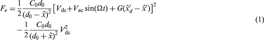
Combined with the work of Shao et al. (2013) and Han et al. (2015a) and taking equation (1) into consideration, the governing equation of motion of this dynamic system can be expressed as

It should be noted that although equation (2) seems to be similar to that of Shao et al. (2013), it actually has two obvious differences. One is the consideration of microbeam mid-plane stretching (nonlinear cubic stiffness), which is more suitable for describing the structural property of doubly clamped microbeams. The other is the expression of electrostatic force generated by two symmetrical electrodes. Thus, our dynamic model is different from that of Shao et al. (2013) to some extent.
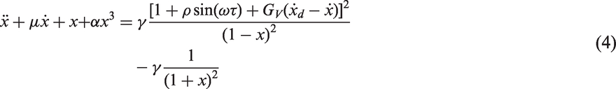
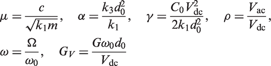
For convenience, we introduce the following nondimensional variables

Substituting equation (3) into equation (2) yields


Expression and stability of equilibrium positions under different α and γ (S: stable; US: unstable).
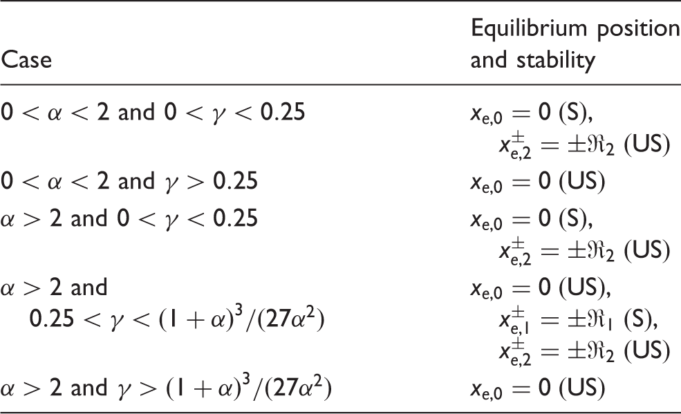
In addition, potential energy and phase portraits of the Hamiltonian system are qualitatively depicted in Figure 2. The dynamic properties can be easily grasped from these figures. Obviously, only the situations in Figures 2(a), (c) and (d) have stable centers. Under the situations in Figures 2(b) and (e), no stable equilibrium position exists. The microresonator undergoes the pull-in instable phenomenon. All these figures coincide with the theoretical results in Table 1.
Potential energy and phase portraits of the corresponding Hamiltonian system. (a) α = 1, γ = 0.1, (b) α = 1, γ = 0.3, (c) α = 3, γ = 0.1, (d) α = 3, γ = 0.255, (e) α = 3, γ = 0.27.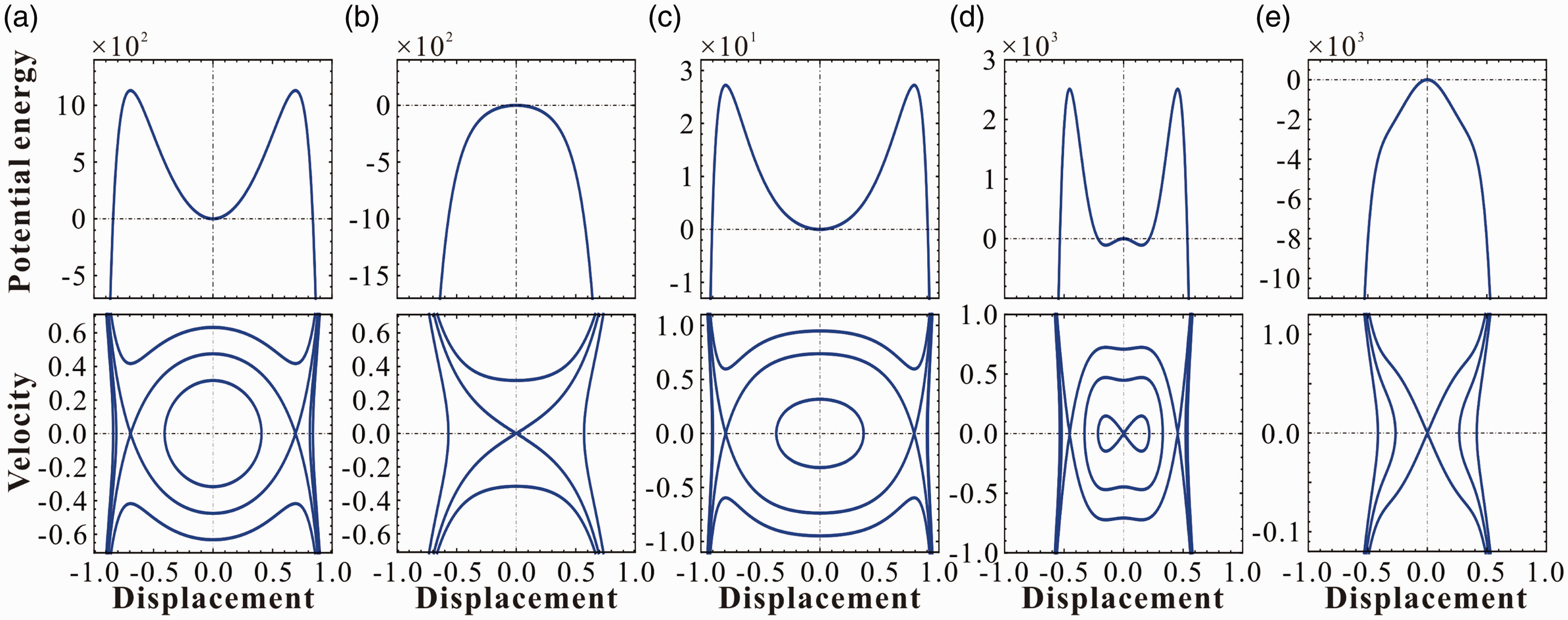
3. Theoretical analysis
In this section, vibration properties of this microresonator with delayed velocity feedback control are theoretically investigated.
3.1. Time delay stability
Generally, harmonic AC voltage applied on MEMS resonators is relatively smaller than DC voltage. Hence, AC excitation can be treated as small disturbances to the MEMS resonator and is approximately ignored here for time delay stability analysis. We introduce 
The characteristic equation of equation (7) can be given by

According to Hu and Wang (2002), linearized system (7) is delay-independent stable if all the roots of 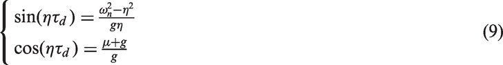
Eliminating 
Based on the above results and Hu and Wang (2002), linearized system (7) is delay-independent stable if p and q satisfy the following conditions

After some calculation, it can be easily derived that if μ and g meet the following condition

Next, the situation with 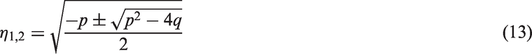
It is easy to prove that 

Next, let 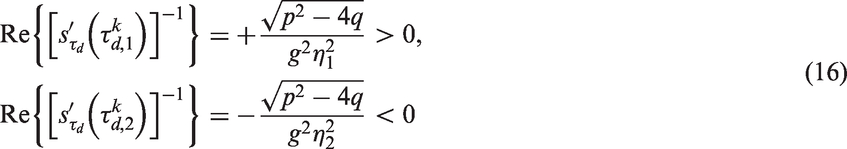
Note that
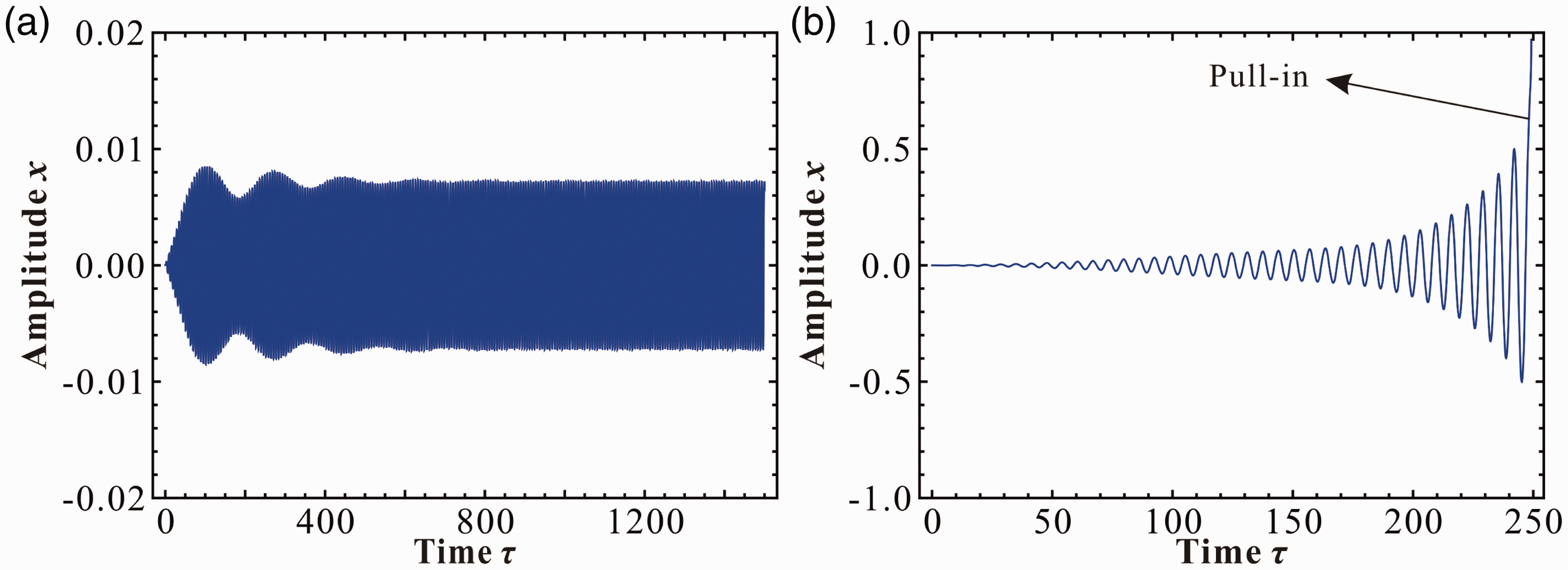
Stability charts depicting nondimensional time delay Stability chart with μ = 0.02 (Τn = 2π/ωn): (a) α = 0.3, γ = 0.01, the origin is a stable equilibrium position; (b) α = 3, γ = 0.26, the origin is an unstable equilibrium position. Displacement response of the resonator with ρ = 0.01, ω = 1, τd = 6.95Tn: (a) g = −0.03; (b) g = −0.08.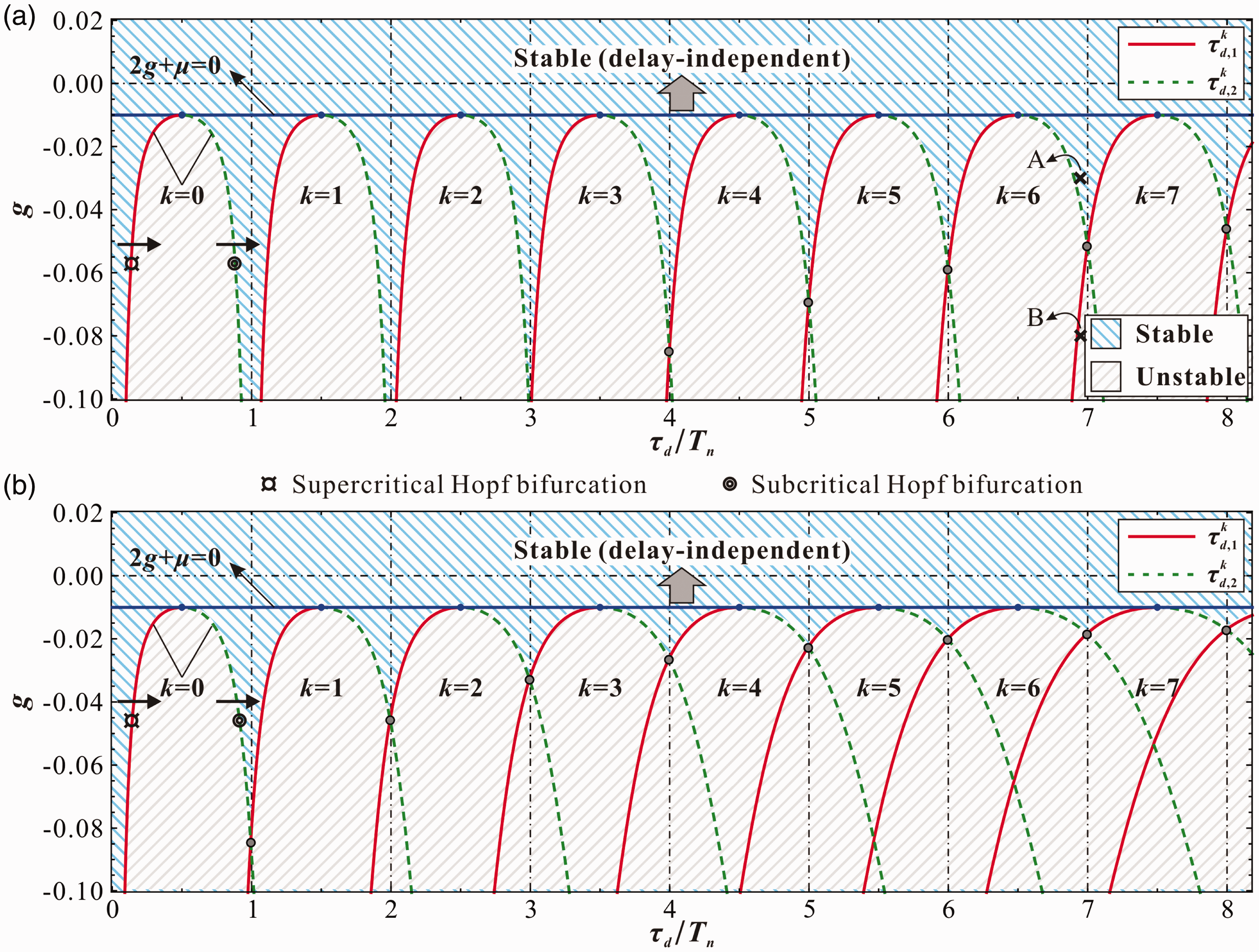
3.2. Perturbation solution
In this section, the small vibration of equation (4) around different equilibrium positions is investigated. Assume the feedback control satisfies the stable condition (Figure 3). Consider the following terms (Shao et al., 2013): 
Here, the primary resonance is investigated (Nayfeh et al., 2007). To describe the nearness of ω to 
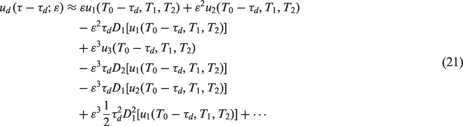
The approximate solution of equation (17) can be written as

By using the following differential operators
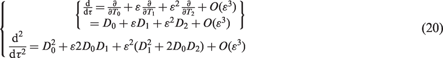
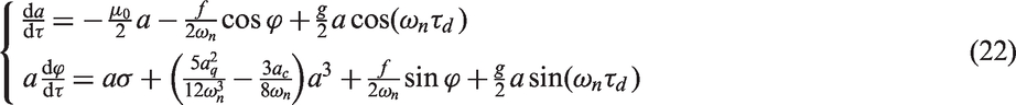
Applying the MMS (Nayfeh, 2011), one can obtain the average equation in polar form
A steady-state response can be obtained by imposing the condition 
The primary resonance peak value of the vibration amplitude and the backbone curve can be decided by


From equations (23)–(25), one can see the following: (1) delayed velocity feedback control may tune the effective damping coefficient
The stability of steady-state motion 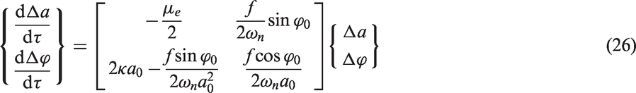
Thus, the stability of steady-state motion depends on the eigenvalues of the coefficient matrix on the right-hand sides of equation (26). The eigenvalue equation can be decided by
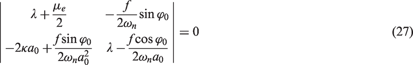

Hence, the steady-state motions are stable when both the following conditions are satisfied

From the expressions of
3.3. Stability analysis
In light of the analysis in Sections 3.1 and 3.2, one can see that the existence of small vibration u depends on two conditions: (1) time delay stability (Figure 3) and (2)
From the expression of g, one can see that for a certain g, DC voltage Stability chart and numerical validation for small vibration in 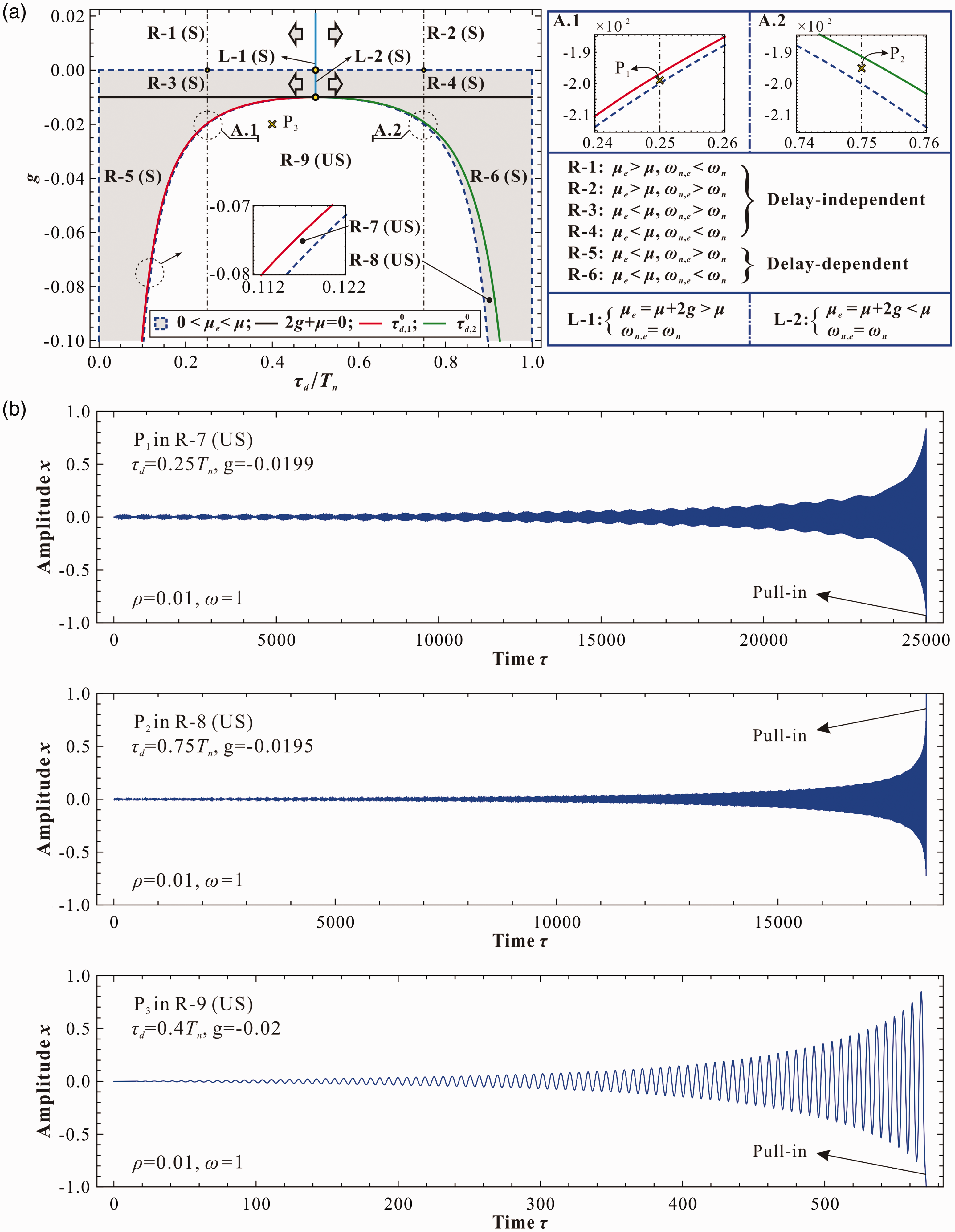
Another important note is that the existence condition of the periodic solution via perturbation analysis (
4. Results
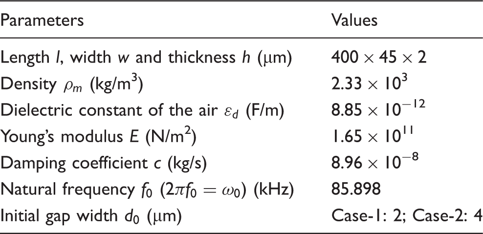
In this section, a specific doubly clamped microbeam (Table 2) with different initial gap widths (Bumkyoo and Lovell, 1997) is considered to investigate the effect of delayed velocity feedback control on the vibration properties of the system. The primary resonance peak value In Case-1, the system has only one stable equilibrium position In Case-2, the system has (a) only one stable equilibrium position, Parameters of a doubly clamped microbeam (Bumkyoo and Lovell, 1997).
4.1. Frequency response
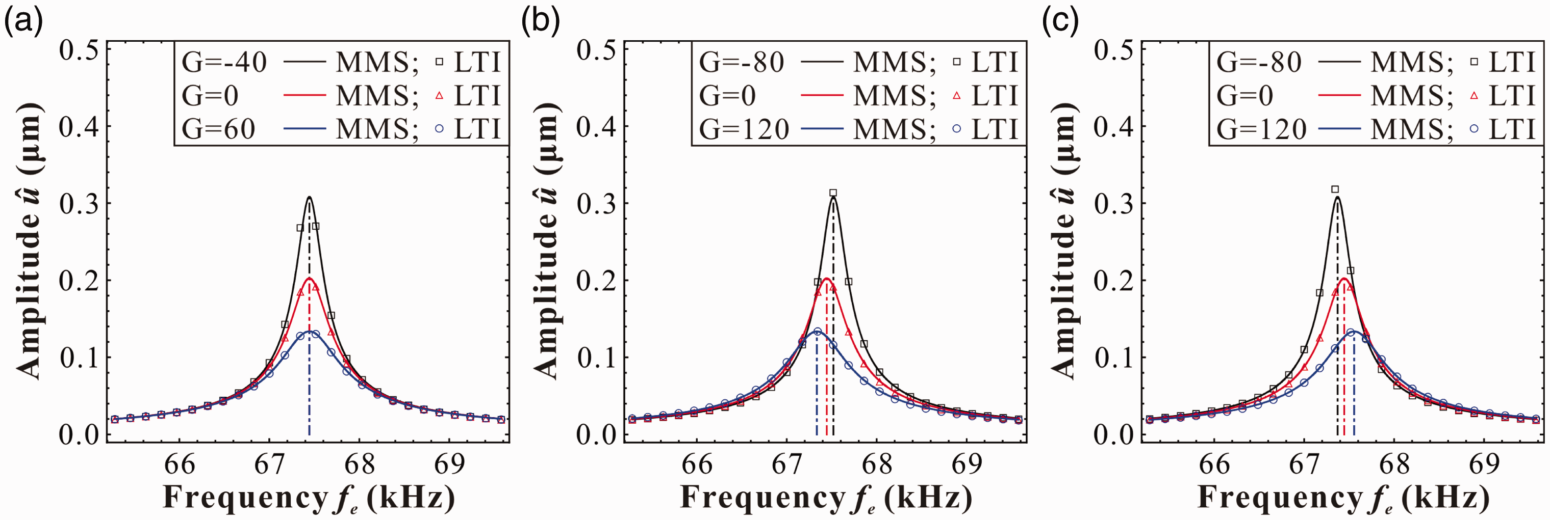
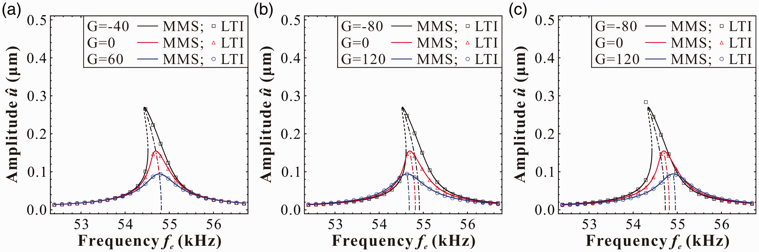
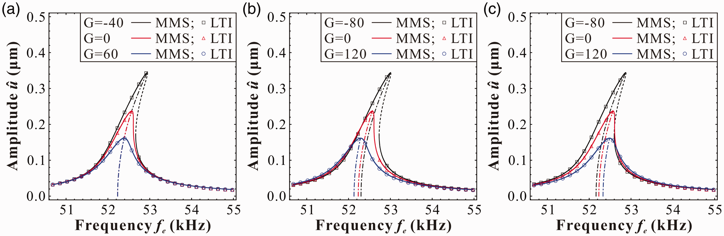
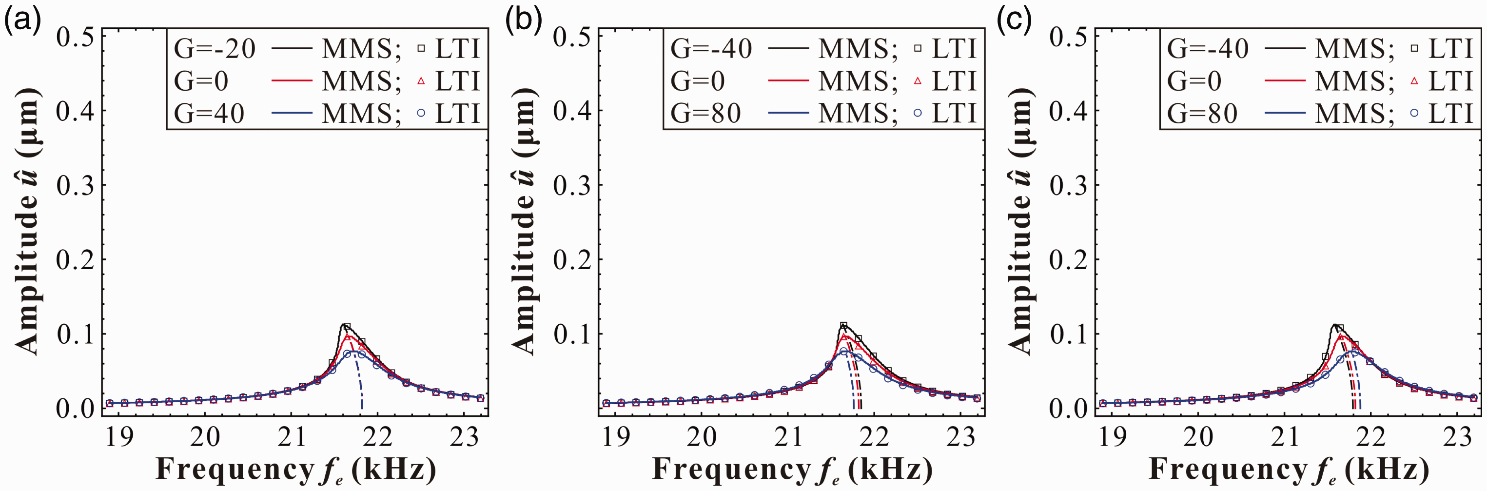
Firstly, we focus on the vibration characteristics in the neighborhood of zero equilibrium position Hardening-type behavior in Case-1 around xe,0 with Vdc = 7 V, Vac = 40 mV; the unit of G is mV/s. (a) τd = Tn/2. (b) τd = Tn/4. (c) τd=3Tn/4. MMS: method of multiple scales; LTI: long time integration. Linear-like behavior in Case-1 around xe,0 with Vdc = 9.653 V, Vac = 20 mV; the unit of G is mV/s. (a) τd = Tn/2. (b) τd = Tn/4. (c) τd=3Tn/4. MMS: method of multiple scales; LTI: long time integration. Softening-type behavior in Case-1 around xe,0 with Vdc = 12 V, Vac = 10 m V; the unit of G is mV/s. (a) τd = Tn/2. (b) τd = Tn/4. (c) τd=3Tn/4. MMS: method of multiple scales; LTI: long time integration. Hardening-type behavior in Case-2 around xe,0 with Vdc = 35 V, Vac = 20 mV; the unit of G is mV/s. (a) τd = Tn/2. (b) τd = Tn/4. (c) τd = 3Tn/4. MMS: method of multiple scales; LTI: long time integration.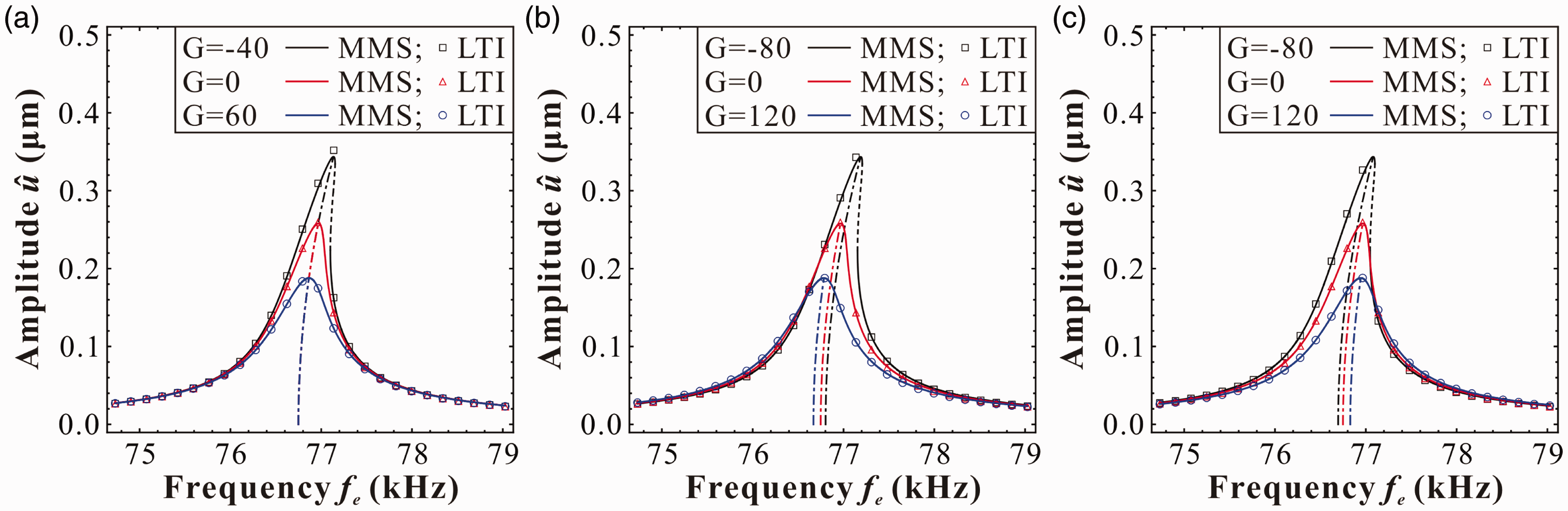
Next, the vibration characteristics around two equilibrium positions Softening-type behavior in Case-2 around Softening-type behavior in Case-2 around 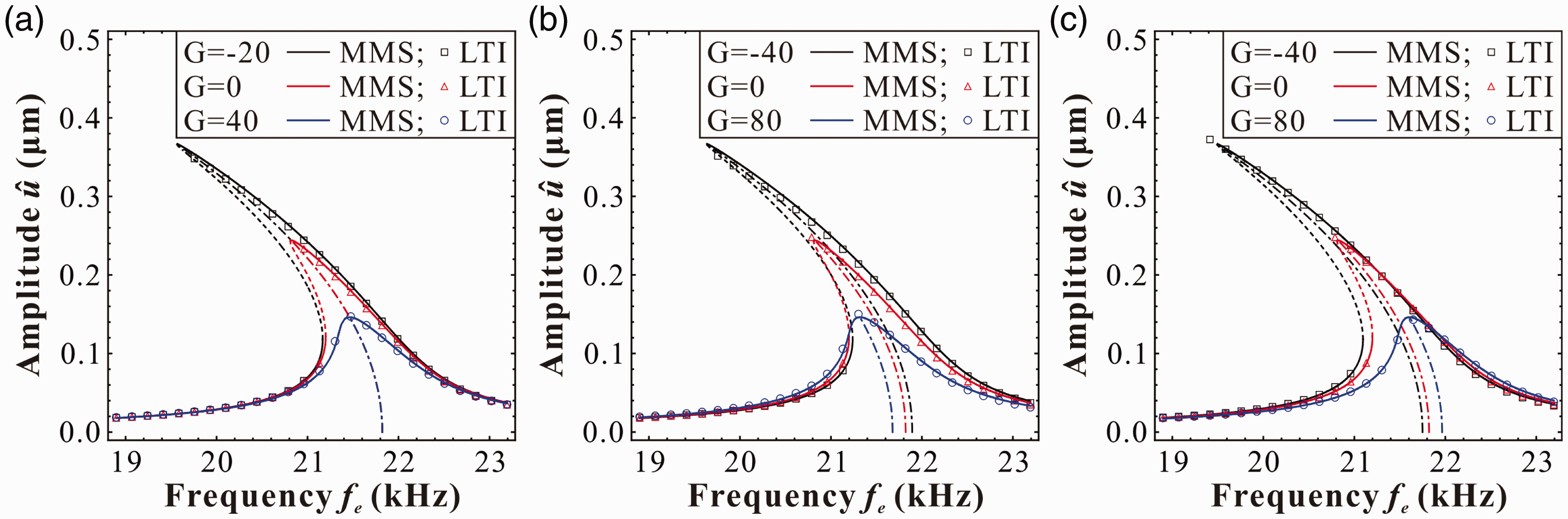
In this section, we study the nonlinear characteristics of the resonator and reveal the dynamic properties with delayed feedback control through case studies (Table 2). In addition, frequency and damping trimming properties are investigated as well to verify our analytical results in Section 3. These phenomena seem to be attractive to MEMS designers. In our following study, we will discuss these aspects in detail and offer some possible design tips.
4.2. Frequency and damping trimming
In fact, damping trimming can occur without frequency trimming when
Firstly, we must emphasize three different natural frequencies: (1) natural frequency of the resonator without DC voltage f0 (the unit is Hz), where
According to the above relationships, one can obtain the variation of equivalent natural frequency versus DC voltage under different initial gap widths, which is shown in Figure 12. In Case-1, the equivalent natural frequency fn decreases with the increasing of DC voltage. Pull-in instability is triggered when The variation of equivalent natural frequency versus direct current (DC) voltage.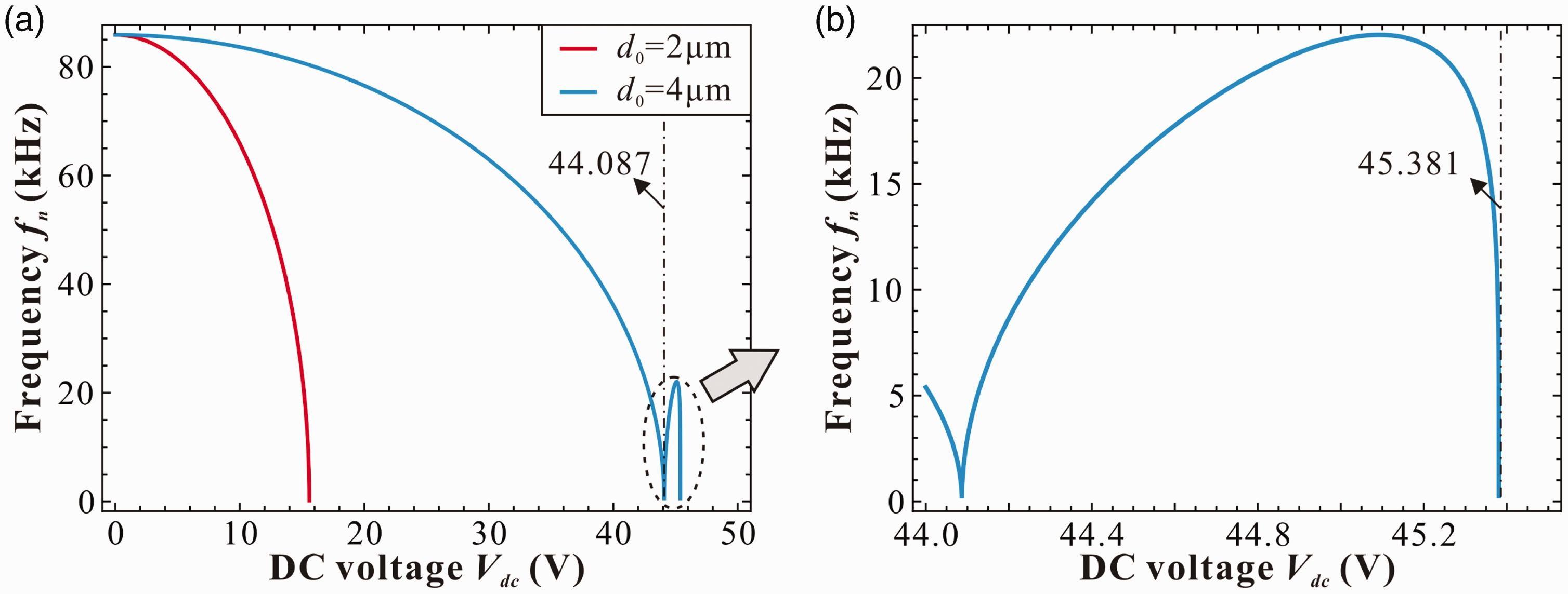
Assume the delayed feedback control does not change the vibration property. For convenience, we only investigate the delay-independent situation with Frequency and damping trimming in Case-1 around xe,0 with Vdc = 6 V; the unit of G is mV/s. (a) Frequency trimming and (b) Damping trimming.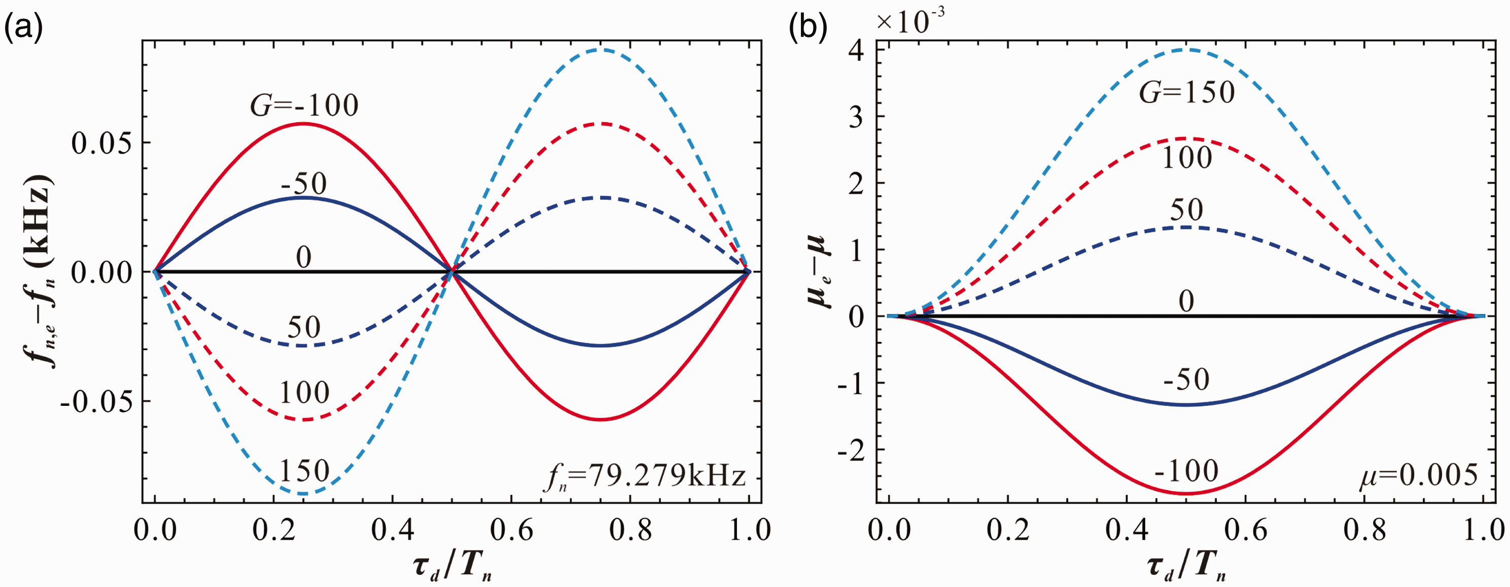
4.3. Optimum operating DC voltage
The linear-like state (Figure 7) seems to be more attractive to MEMS designers (Han et al., 2015a) because one can use delayed velocity feedback control to realize system frequency/damping trimming and, hence, enable the operation of MEMS resonators at a larger amplitude and more powerful signal (Alsaleem and Younis, 2010, 2011). Under this vibration state, one must meet the following condition:
In Figure 7, one can see that the analytical results (MMS, equation (23) in dimensional form) agree well with the numerical results (LTI, equation (2)) when the amplitude of the resonator 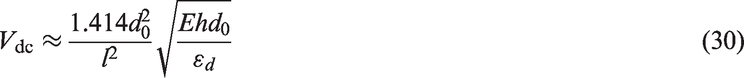

Based on equations (30) and (31), one can obtain the optimum operating DC voltage (solid lines) and its equivalent natural frequency (dashed lines) for different microbeam-based resonators. Figure 14 shows some optimum design curves depicting these two parameters versus the initial gap width. It is obvious from Figure 14(a) that the increase of the length of the microbeam can decrease the available design region of DC voltage and its equivalent natural frequency. However, the cut-off line (dot-dashed line) is invariable, as the critical initial gap width Optimum operating direct current (DC) voltage (solid line) and its corresponding equivalent natural frequency (dashed line) versus the initial gap width d0: (a) under different lengths l; (b) under different thicknesses h. Design case with feedback gain G = −50 mV/s (R: Vac = 19 mV, τd = Tn/4; Z: Vac = 25 mV, τd = 0; L: Vac = 19 mV, τd = 3Tn/4). MMS: method of multiple scales; LTI: long time integration.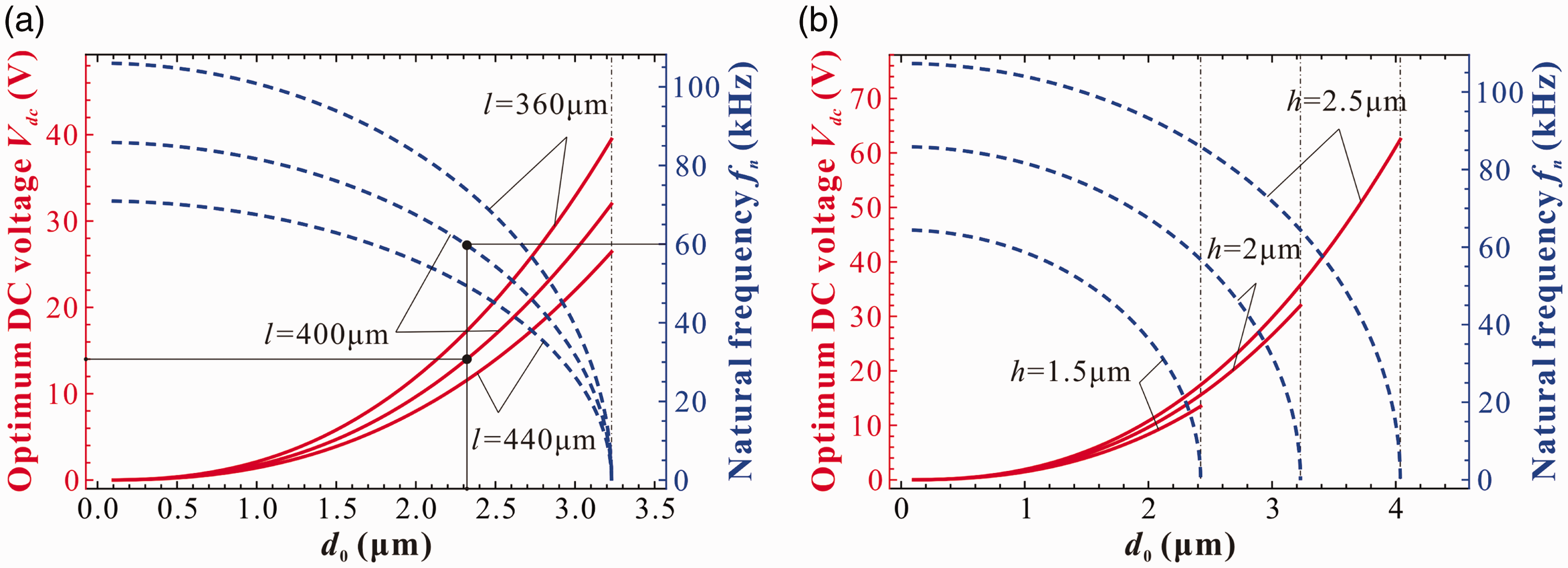

5. Discussion and conclusions
This paper established a simplified 1-DOF model to describe a doubly clamped microbeam actuated by two symmetrically located electrodes with delayed velocity feedback control. Through the analysis of the linearized time-delayed equation, the stable region depicting delay time versus feedback gain beyond Hopf bifurcation was obtained. Different from the periodic stability description as mentioned by Shao et al. (2013), we found that the stable region was nonperiodic and decreased with the increase of period k. Stability switches (Wang and Hu, 2000) do exist in this dynamic system. Then, under the small vibration assumption, an approximate analytical solution to characterize the nonlinear dynamics of the system was obtained by the application of the MMS. Two critical conditions to guarantee the existence and stability of small vibration solutions were deduced. Following this, a stability chart with k = 0, considering Hopf bifurcation and the above two critical conditions, was drawn. We found that the existence condition
We also investigated the hardening, softening and linear-like behaviors of the resonator with feedback control through case studies. What we found was that the feedback control could not qualitatively affect the above dynamic properties. However, both the delay time and feedback gain could tune the effective damping and natural frequency of the system. Then, we discussed the frequency and damping trimming properties in detail and concluded some qualitative trimming tips. Furthermore, we focused our attention on the linear-like behavior and derived two formulas to estimate the optimum operating DC voltage and its corresponding natural frequency. Through a case study, the designed initial gap width and DC voltage were obtained according to the predesigned working frequency of a specific resonator. The above analysis demonstrates that DC voltage can be used to tune the equivalent natural frequency and delayed velocity feedback control can realize the fine-tuning of frequency and damping.
The entire investigation may contain some potential applications in dynamic MEMS devices (Alsaleem and Younis, 2010, 2011). For example, one can obtain the control parameter scopes against dynamic instability, and then increase system stability via damping trimming, changing the resonance frequency via frequency trimming. In addition, linear-like design and control analysis have potential in generating a more powerful signal, thus improving the MEMS resonator performance in mass sensing.
Here, it should be noted that all of the analytical results are obtained based on the small vibration assumption. Both the stability analysis via linearized assumption and the dynamic analysis via perturbation approach can be effective only for weakly nonlinear systems and small vibrations in the neighborhood of the equilibrium position. Undergoing large motion, other feasible analysis methods such as the Shooting Method or the Finite Difference Method should be chosen for dynamic and control analyses (Masri et al., 2015). Moreover, many other factors, such as the fringing effect, residue stress, squeeze film damping, and the scale effect, which may affect system dynamics, are not taken into account here during the analysis. These factors can indeed affect the performance of the system to some extent and need to be further investigated. Although our analysis of the 1-DOF model can only provide an approximate understanding of this system in a relatively simple way, it can actually provide some references for the subsequent analysis. Guided by these analytical results, further research can be carried out to focus on the distributed model and to investigate the effects of more complicated impact factors on system static or dynamic behaviors.
Footnotes
Declaration of Conflicting Interests
The author(s) declared the following potential conflicts of interest with respect to the research, authorship, and/or publication of this article: This manuscript is our original unpublished work and it is not being submitted to any other journal for reviews. No data have been fabricated or manipulated (including images) to support our conclusions. The authors declare that we have no conflict of interest and agree to submit this manuscript to Journal of Vibration and Control. Besides, the manuscript has no research results involving human participants and/or animals.
Funding
The author(s) disclosed receipt of the following financial support for the research, authorship, and/or publication of this article: The work was supported by the National Natural Science Foundation of China (grant number 11372210, 51405343, 11302149), the Tianjin Research Program of Application Foundation and Advanced Technology (grant number 15JCQNJC05000) and the Scientific Research Foundation of Tianjin University of Technology and Education (Grant number KYQD1701, KYQD16009).