In this paper, a robust output feedback control design is developed for suppression of aeroelastic vibration of a 2-DOF nonlinear wing section system. The aeroelastic system operates in a quasi-steady aerodynamic incompressible flowfield and is actuated using a combination of a leading-edge (LE) and a trailing-edge (TE) flap. By only utilizing measurements of pitching and plunging deflections, an innovative Lyapunov-based procedure is used to design sliding mode control inputs for the LE and TE control surface deflections. The closed-loop system is shown to have semi-global asymptotic stability even in the presence of model uncertainty and unknown external gust loading. Extensive simulation results under a variety of scenarios show the effectiveness of the control strategy.
Aeroelastic stability and flutter suppression are important topics that have been investigated by numerous researchers over the past few years. Flutter instability jeopardizes aircraft performance and can affect its survivability. While it is possible to compute flutter boundaries for an aircraft, significant decays of the flutter speed are possible during its operational life which can cause flutter to set in. To increase the flutter speed, many passive methods have been employed such as added structural stiffness, mass balancing, and speed restrictions (Dowell, 1978). However, these attempts have the unintended consequences of increase in aircraft weight and reduction of nominal performance (Marzocca et al., 2001, 2002). Therefore, a slew of control strategies have been developed for active flutter suppression to expand the flight envelope as well as for superior vibration suppression at pre-flutter speeds (Marzocca et al., 2004). In the last two decades, the advances of active control technology have rendered the applications of active flutter suppression and active vibration control systems feasible (Lazarus et al., 1995; Vipperman et al., 1998; Yuan et al., 2004). Assuming linear structures and aerodynamics, early researchers designed and implemented linear controllers for the problem. Practical gust load alleviation and flutter suppression control laws were provided by Gangsaas et al. (1981) based on the LQG methodology. In Karpel (1982), a pole-placement technique was utilized for a partial-state feedback control law for flutter suppression, while Horikawa and Dowell (1979) adopted proportional gain feedback methods, developed from root locus plots, to perform flutter suppression and load alleviation.
Starting in the late nineties, nonlinear control strategies for flutter suppression of aeroelastic systems started to emerge. Ko et al. (1997, 1999) designed a nonlinear adaptive controller feedback methodology proposed for wing section with polynomial structural torsional nonlinearity. Lee and Singh (2009) proposed an immersion and invariance approach-based adaptive control design to solve the flutter suppression problem for aeroelastic wing sections with structural nonlinearity. A proportional-integral observer-based robust control strategy for the purpose of active flutter suppression of a nonlinear 2-DOF wing-flap system was presented in Zhang and Soffker (2009). More recently, Lee and Singh (2013) proposed an adaptive control law for the suppression of aeroelastic oscillations using pitch angle and pitch rate feedback with a state predictor in the presence of large parameter uncertainties and triangular, sinusoidal, and exponential gust loads. In Zhang et al. (2013) and Zhang and Behal (2014), a partial-state feedback adaptive controller and a robust integral of the sign of the error (RISE)-based control design were proposed for aeroelastic vibration suppression under unsteady flow. In addition to the aforementioned single-input designs, recent research works (e.g. Platanitis and Strganac, 2004, 2005; Wang et al., 2010, 2011; Zhang 2015; Zhang et al., 2015a;) have considered the utilization of both leading-edge (LECS) and trailing-edge (TECS) control surface as control surfaces operating in tandem to improve the system performance via design of a variety of multiple-input, multiple-output (MIMO) control strategies. In our most recent work (Zhang et al., 2015a), an adaptive control design for a 4-DOF wing section model was proposed to stabilize an unsteady aeroelastic system with LE and TE flaps. In Wang et al. (2012), a full-state continuous robust control design was based on integration of the signum of a filtered tracking error and an adaptation law.
Another focus of aeroservoelasticity researchers has been output feedback control strategies. In Zeng and Singh (1998), a variable structure model reference adaptive control-based output feedback control design was applied to aeroelastic systems with only a TECS. Backstepping-based output feedback nonlinear control strategies were designed for the control of an aeroelastic system for flutter suppression in Xing and Singh (2000), Bhoir and Singh (2004) and Reddy et al. (2007), whereas in Zhang and Singh (2001), high-gain observer, output feedback linearization, and adaptive control strategies have been derived to account for the effect of nonlinear structural stiffness. The work in Patil and Hodges (2002) designed a very simple optimal constant gain output feedback-based controller for a nonlinear aeroelastic system. In Baranyi (2006), an LMI-based observer for the prototypical aeroelastic wing section was built to estimate the practically unmeasurable state values from the selected output values and, based on those estimated states, an output feedback control strategy was designed. In Lee and Singh (2007), a first-order dynamic compensator was introduced for a global robust output feedback control design for an aeroelastic system with only a TECS. In Wang et al., (2011) and Zhang et al. (2012), a neural network-based full-state feedforward/feedback controller for aeroelastic vibration suppression was designed to achieve a uniformly ultimately bounded stability result.
Most of the previously proposed output feedback control algorithms have been developed by building a state observer to avoid measurements of the rate of outputs, which requires the knowledge of the model parameters. In this paper, an output feedback controller without observer is proposed to asymptotically stabilize a 2-DOF airfoil system under quasi-steady flow with unstructured nonlinear uncertainties and bounded unknown external disturbances. The goal of this paper is to utilize LECS and TECS deflection as actuators in the design of a robust output feedback controller to suppress the vibrations for a prototypical aeroelastic system. A suite of nonlinear analysis and synthesis techniques has been brought to bear to solve this novel problem. The proposed controller requires only minimal knowledge of the system model, namely, the signs of the leading principal minors of the high-frequency gain matrix. To the best of our knowledge, a MIMO output feedback controller for aeroelastic vibration suppression that is robust to unstructured model uncertainty and exogenous disturbances has not been reported in the literature. A suite of nonlinear analysis and synthesis techniques has been brought to bear to solve this novel problem. Inspired by Sadegh and Horowitz (1990), we design a specialized filtered tracking error by using measurements of the pitch and plunge values only; that is, measurements of pitch and plunge rates are not needed. As similarly done in Wang et al. (2012), an adaptation law is designed to compensate for the structured disturbance induced by the coupling between the two control inputs. A Lyapunov-based analysis is applied to show that semi-global asymptotic stability can be obtained for the pitching and plunging tracking errors under application of the proposed control design. The Lyapunov-based analysis theoretically guarantees robustness of the stability properties under bounded external gust disturbances. Due to the nature of sliding mode control, this control design requires a higher actuator bandwidth than needed in Wang et al. (2011). To alleviate this requirement, a tangent function or saturation function can be used in practice to substitute for the signum function in the control law.
2. Aeroelastic model and error system development
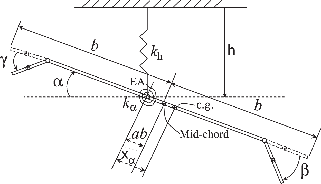
A wing section model with 2-DOFs in plunging displacement h, pitching angle α, TECS deflection and LECS deflection γ is presented in Figure 1.
Wing section with leading- and trailing-edge flaps.
where L, M are the quasi-steady lift and aerodynamic moment Theodorsen T and Garrick IE (1942) given as
while Lg, Mg are the aerodynamic loads due to the bounded external disturbance Librescu L, Na S, Marzocca P, et al. (2005) described as follows
where denotes the disturbance velocity while τ is a dimensionless time variable defined as . The reader is referred to Appendix A for a list of the model parameters utilized in (2), (3), and Figure 1.
The governing equations (1) can be transformed using (2) into the following input-output representation:
where is a system output vector, x and are the state variables, denotes the control input vector. Here, represents the zero-input acceleration of the disturbance free system, denotes the exogenous disturbance affecting the system, while G denotes the input gain matrix for the system. Explicit definitions for and have been provided in Appendix A. We note here that contains uncertain nonlinearities due to the existence of .
3. Error system and open-loop error dynamics
The objective of this paper is to design a sliding mode controller to suppress the vibrations in the pitching (i.e., α) and plunging (i.e., h) degrees of freedom using only measurements of these output variables. To facilitate the control design, the output tracking error is defined as
where is the desired bounded output variable that is designed to be C2 smooth. The desired output can be chosen to go to the origin along predefined trajectories or simply be set identically to zero. In order to compensate for lack of measurements of , a measurable filter tracking error is designed as
where
is chosen to have a lower triangular structure in deference to the ensuing stability analysis, and k3 are chosen such that is Hurwitz, while is generated via the following differential expression
where denotes an n × n identity matrix. In previous designs for the filter tracking error e, the gain has been chosen to be a scalar constant, but the more general MIMO problem under consideration here necessitates an innovative lower triangular structure for which will allow for the design of a singularity free control law that guarantees asymptotic stability. This aspect will make itself evident subsequently in the stability proof section. An unimplementable but analytically convenient expression for the dynamics of can be written as follows:
where is an immeasurable filtered tracking error defined as
based on the definitions of (5), (6), and (8). We define a composite error vector as follows:
Finally, based on the definitions of error signals in (6–10), we define a measurable auxiliary error signal as follows:
such that
After taking the time derivative of along the trajectory of (4) and performing some algebraic manipulation, the open-loop filtered tracking error dynamics can be compactly written as follows:
where we have applied an SDU decomposition (Strang, 1980; Morse, 1993) to the control gain matrix G as follows:
where is a symmetric positive-definite matrix, T, is a diagonal matrix with +1 or –1 as its diagonal entries, and U is a unit upper triangular matrix. Since the direction of control application is assumed to be known, thus the diagonal matrix D comprising the signs of the leading principal minors of G is assumed to be known accordingly. The auxiliary function is defined as
The auxiliary signal is defined as follows:
where Uij denotes the entry of the U matrix. From the structure of (16), one can split into two components
where and are defined as
Given the fact that one can assert the a prior boundedness of , i.e.,. After substituting (18) and (19) into (14), one can rewrite the open-loop error dynamics as follows:
4. Control design and stability analysis
4.1. Structure of control law
Given the foregoing analysis, we propose the following output feedback control law:
where the filtered errors , E, the control gain matrix K have been previously defined. Here, is the desired gain matrix defined as . The adaptation term is where the regressor and the estimation parameter adaptation law is designed as
where Γ is a positive adaptation gain. By substituting (21) into (20), one can obtain the following closed-loop error dynamics:
After substituting (21) into (17), can be explicitly rewritten as
which can be split into two parts as follows:
where
4.2. Stability analysis
To facilitate the stability analysis of (23) with respect to the control design of (21), we state the following preliminary Lemma:
Lemma 1
Similar to Xian et al. (2004), an auxiliary function is defined as follows:
If the control gains are chosen as follows:
then one can obtain the following bound
where
Proof
See Appendix B.
A non-negative Lyapunov function candidate V is defined as
where By taking derivative of along (9), (10), and (23), one can obtain
which can be upperbounded as follows:
where (26) is utilized. By applying the Mean Value theorem (Simmons, 1996) to in (19) and definition of Λ in (25), one can have
where denote globally invertible nondecreasing functions. Thus, by using (32) and (31), one can further upperbound as
where is defined in (7). Since is Hurwitz and T is a positive-definite (PD) matrix, there exists a diagonal PD matrix such that
By solving (34), one can have
where denotes the determinant of T. By utilizing (34) and substituting for k3 using the last equation in (35), can be further bounded as follows:
After completing the squares on the bracketed term in (36), the following upperbound is obtained:
By utilizing (35), one can choose K properly to ensure q large enough such that the bracketed term in (37) is positive. Thus in (37) can be upper bounded as follows:
on the set
The inequality of (38) implies that is negative semi-definite on the set given in (39). Given (30) and (38), standard signal chasing arguments can be utilized to show the boundedness of all plant signals and control input in closed-loop operation. Thus, the positive semi-definite function can be proven to be uniformly continuous. Now, one can use Theorem 8.4 of Khalil (1996) to show provided where
Since the region of attraction given by can be made arbitrarily large by increasing the control gains, the result is semi-global.
4.3. Control law design: Choice of control gains
It is clear to see from the stability analysis that q > 0 are proportional to the size of the initial errors and that sufficiently large q will be adequate for ensuring stability and convergence. However, the control design proposed in (21) requires selection of which has been shown in (35) to be related to q via the closed-form solution shown in (35). Even though our analysis guarantees the existence of ki, it is, however, not easy to prescribe choices for ki since the mi are considered to be uncertain. As an example, one can see from (35) that k1, k2 cannot be chosen to be arbitrarily large. In this section, our goal is to prescribe boundaries for ki in terms of the upper and lower bounds on the eigenvalues of These boundaries are meant to assist the design engineer in choosing control gains.
After a few algebraic manipulations, (34) can be rewritten into the following form:
on (41) and (44), one can obtain a useful upperbound for from
One can use these upperbounds in conjunction with the fact that (since is Hurwitz). From (35), the sign of k2 can be obtained as follows:
By utilizing the facts that , and T are all positive, one can have
Since , one can obtain
where gij denotes the element of the matrix G. For the nominal system as will be presented in Section 5, k2 is seen to be negative.
Remark 2
The aforementioned adaptation law for in (22) cannot be implemented directly since the variable r1 is unavailable for measurement. However, integration by parts can be utilized to obtain the following measurable expression for :
where
∪… ∪ ∪ ∪… ∪ . , , represents all the interval when , and , represents all the interval when . Here we have taken advantage of the fact that E2 is measurable and that the integral exists due to the continuity of signals as shown above.
5. Simulation results and discussion
5.1. Model and controller parameters
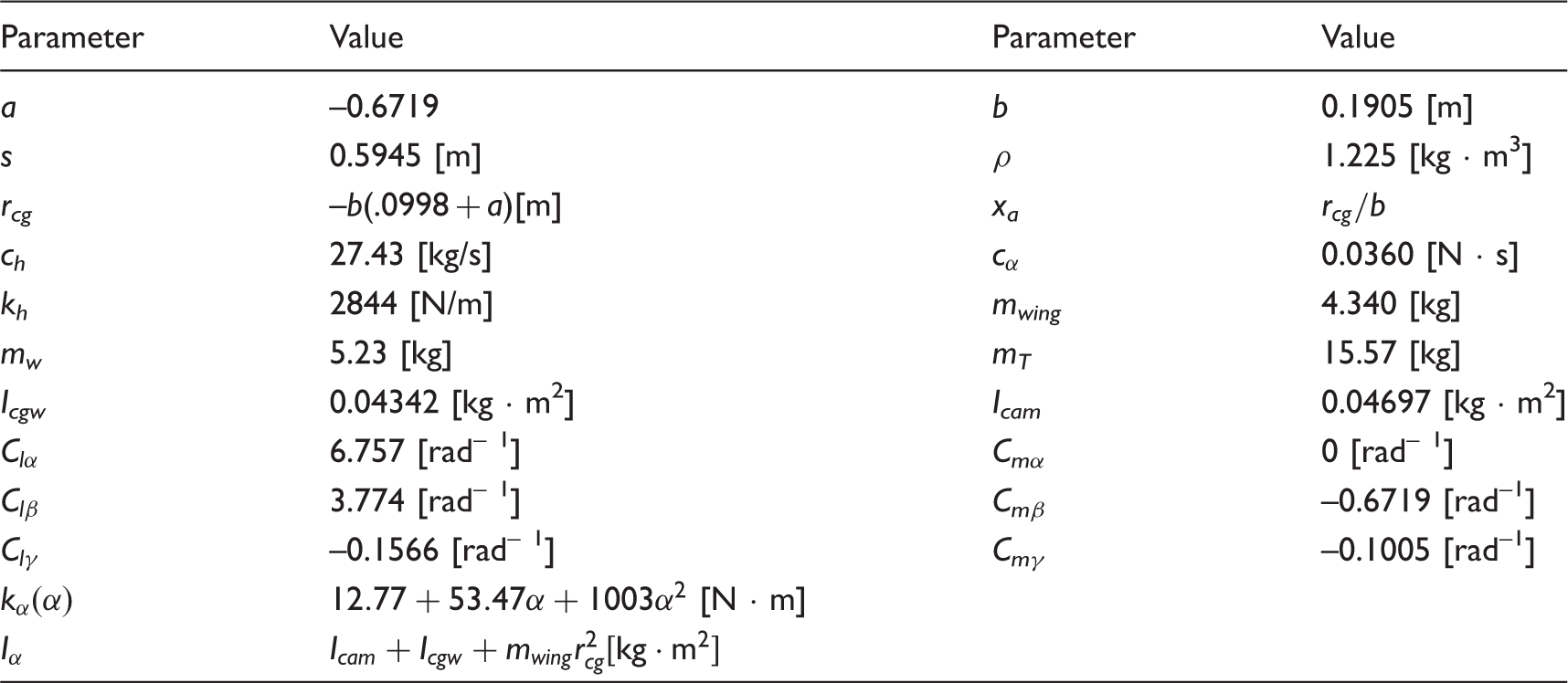
In this section, numerical simulation results are presented for a nonlinear wing section model controlled by the TE- and LE-flaps and subjected to external disturbances. The model parameters utilized in the simulation are the same as used in Platanitis and Strganac (2004) and listed in Table 1, while a block diagram for the controller is shown in Figure 1.
Wing section parameters.
Parameter
Value
Parameter
Value
a
–0.6719
b
0.1905 [m]
s
0.5945 [m]
ρ
1.225 [kg · m3]
rcg
–b(.0998 + a)[m]
xa
ch
27.43 [kg/s]
0.0360 [N · s]
kh
2844 [N/m]
mwing
4.340 [kg]
mw
5.23 [kg]
mT
15.57 [kg]
Icgw
0.04342 [kg · m2]
Icam
0.04697 [kg · m2]
6.757 [rad– 1]
Cmα
0 [rad– 1]
3.774 [rad– 1]
Cmβ
–0.6719 [rad–1]
–0.1566 [rad– 1]
Cmγ
–0.1005 [rad–1]
[N · m]
The pitching spring stiffness is modeled as a polynomial nonlinearity and selected as [N · m]. Note that all these parameters are used to simulate the wing section model but are considered unknown for the purpose of control design. The desired trajectory variables are simply set to zero. The initial conditions for pitching angle and plunge displacement h(t) are set to be [deg] and [m], respectively, while all other plant state variables are initially selected to be zero. The signs of the leading principal minors of the high-frequency gain matrix G are encoded in the diagonal matrix D which is explicitly given as for this case.
Note that the robust output feedback controller designed here depends only on the knowledge of D but not on the knowledge of S and U. Both the leading-edge β and trailing-edge γ flaps are constrained to vary between ± 15
Three kinds of external disturbances are considered according to Marzocca et al. (2001). The first type of external disturbance is modeled as a triangular pulse, whose velocity distribution can be given as:
where denotes a unit step function, and tG = 0.25 [s], and [m/s]. This triangular pulse lasts 0.5 seconds from t = 0 [s] to t = 0.5 [s]. The second type of external disturbance—one that is sustained beyond the transient response time of the closed-loop aeroelastic system—is given in the form of graded gust, whose velocity distribution can be expressed as follows:
where w0is chosen according to the simulation setting. The third disturbance is given in the form of sinusoidal gust with the following velocity distribution function :
where [rad/s] while w0 is selected based on different simulation settings. Thus, these three disturbance profiles test the system response to ephemeral disturbance, steady sustained disturbance, and time-varying sustained disturbance. Also note that the triangular gust tested in this section is very similar to the traditional 1-cosine gust-type function—both of which can be classified as ephemeral disturbances.
5.2. Numerical simulation results
The output feedback controller of (21) is implemented via the error variables defined in (5), (6), (8), and (12). Since signum function requires unlimited bandwidth of actuator, to solve this problem and avoid chattering, we use a steep tangent hyperbolic function to approximate it such that the control law becomes
where can be used to adjust steepness of the control input and it is set . The parameters for the controller are listed in Table 2.
Simulation parameters.
Parameter
Pre-flutter
Post-flutter
Kd
diag
diag
K
Γ
3
3
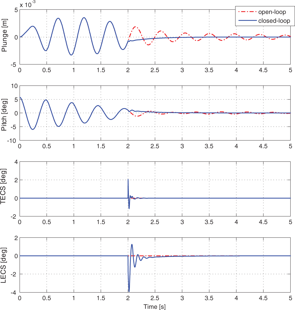
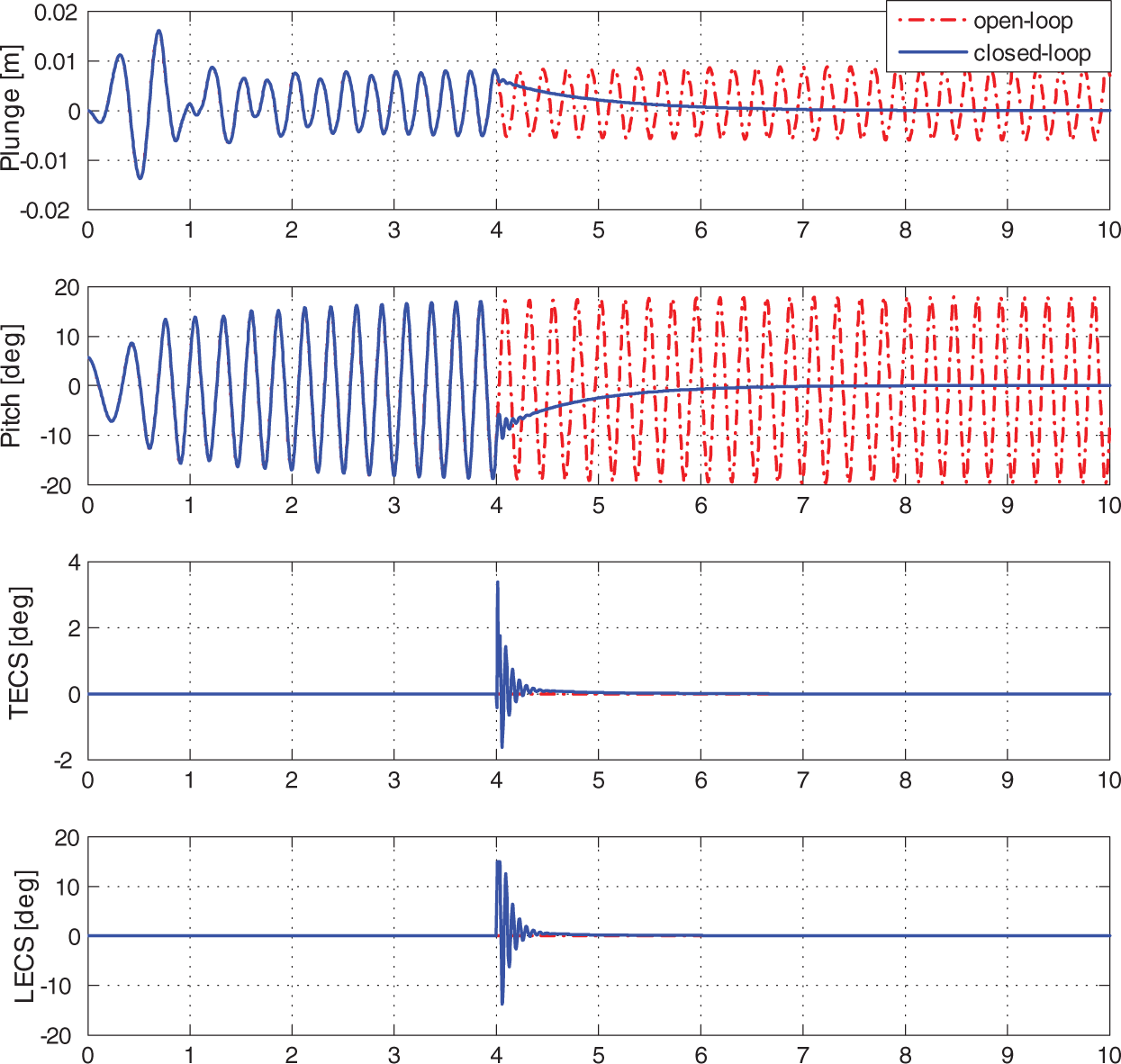
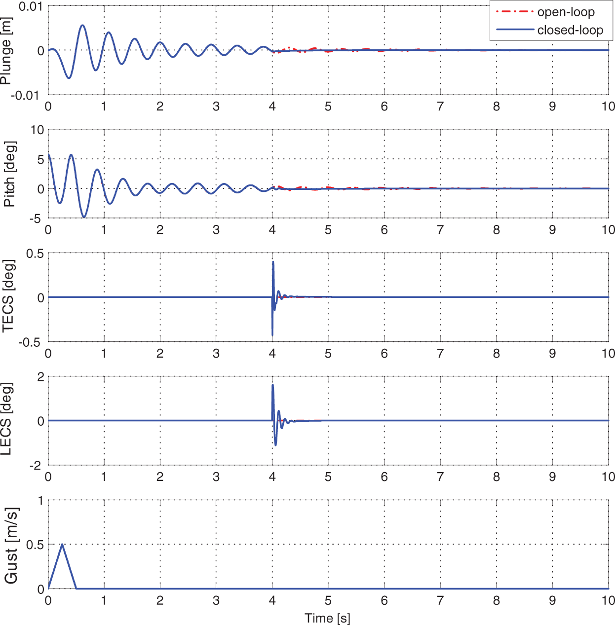
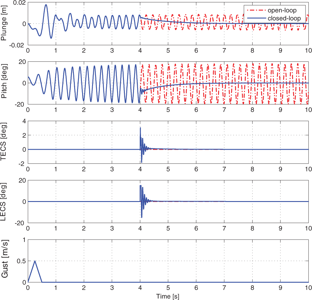
The contribution of those disturbances shown in (52), (53) and (54) to the system response will be presented in the form of gust loading as shown in (3). Both disturbance velocity distribution and the corresponding gust load will be presented along with the system response. Various simulations are run to test the nominal system response as well as response under the external disturbances given in (52–54). Both the leading-edge β and trailing-edge γ flaps were constrained to vary between ± 15 . Figure 2 shows the open- and closed-loop system response at pre-flutter speed [m/s] without gust disturbance. The controller is turned on at Even though the open-loop plunging and pitching displacements for the system can converge in finite time at pre-flutter speed, the application of closed-loop control reduces the convergence time as shown in Figure 2. Figure 3 shows open- and closed-loop system response without gust disturbance at post-flutter speed [m/s] while the controller is turned on at . As we can see, the controller has stabilized plunging and pitching displacement in .
Open- and closed-loop system respone without gust disturbance at pre-flutter speed [m/s].
Open- and closed-loop system respone without gust disturbance at post-flutter speed [m/s].
Figures 4 and 5 are system responses under triangular disturbance at pre- and post-flutter speed. In these two sets of simulations, the disturbance is introduced at while the controller is turned on at . From these two figures, we can see that the controller has effectively suppressed vibrations in the pitching displacement α and plunging displacement h. At pre-flutter speed, Figure 4 shows that the controller has remarkably decreased the convergence time from to and eliminated the errors caused by the tail of the disturbance. In Figure 5, one can see that the controller has effectively suppressed the oscillation of pitching and plunging displacement in about Figure 6 in Wang et al. (2012) provided a good comparison to show the advantages of the control design in this paper. System convergence time is greatly shorten from 4[s] in Wang et al. (2012) to less than 1 [s] in this paper, subject to the same external disturbance.
Control input of closed-loop system under triangular disturbance at pre-flutter speed [m/s].
Open- and closed-loop system response under triangular gust at post-flutter speed [m/s].
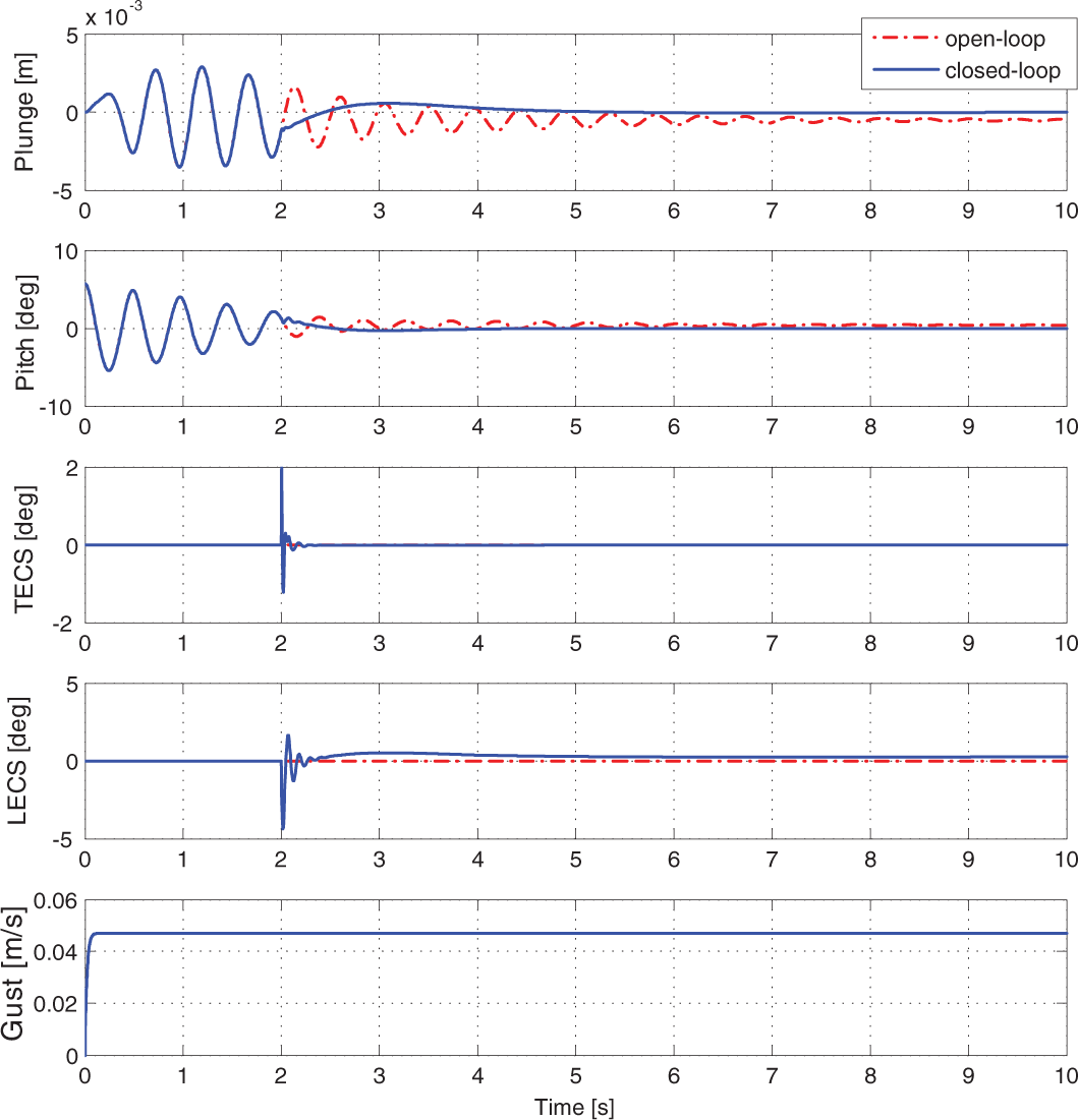
Open- and closed-loop system response under graded gust at pre-flutter speed .
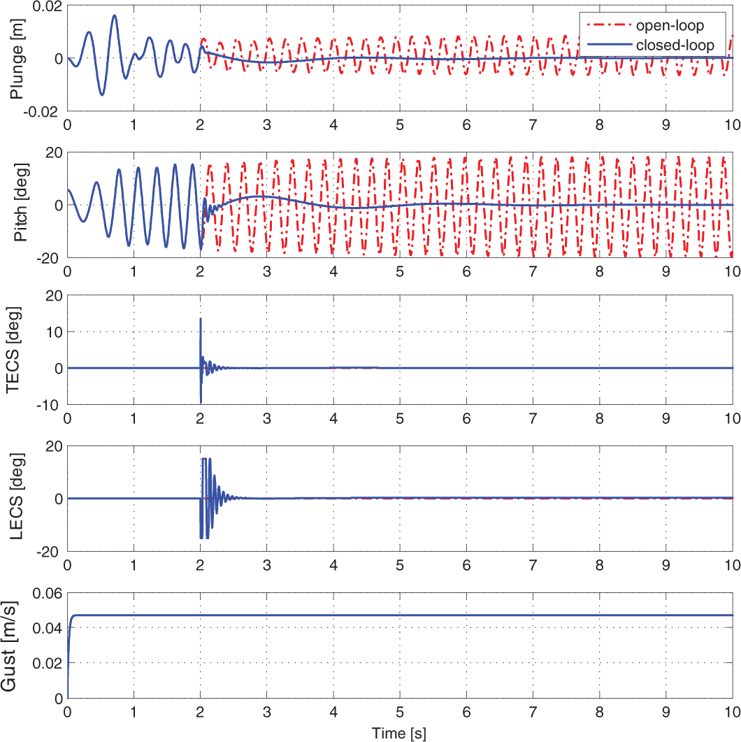
The system responses under graded disturbance are shown in Figures 6 and 7. The controller is turned on at As seen in Figure 6, due to the persistence of the graded disturbance, the open-loop system cannot converge at pre-flutter speed. The closed-loop system response at pre- and post-flutter speed, as observed from Figures 6 and 7, shows rapid regulation of the outputs even under the persistent disturbance. As expected, the persistent disturbance causes the control signals not to converge to zero along with the output.
Open- and closed-loop system response under graded gust at post-flutter speed [m/s].
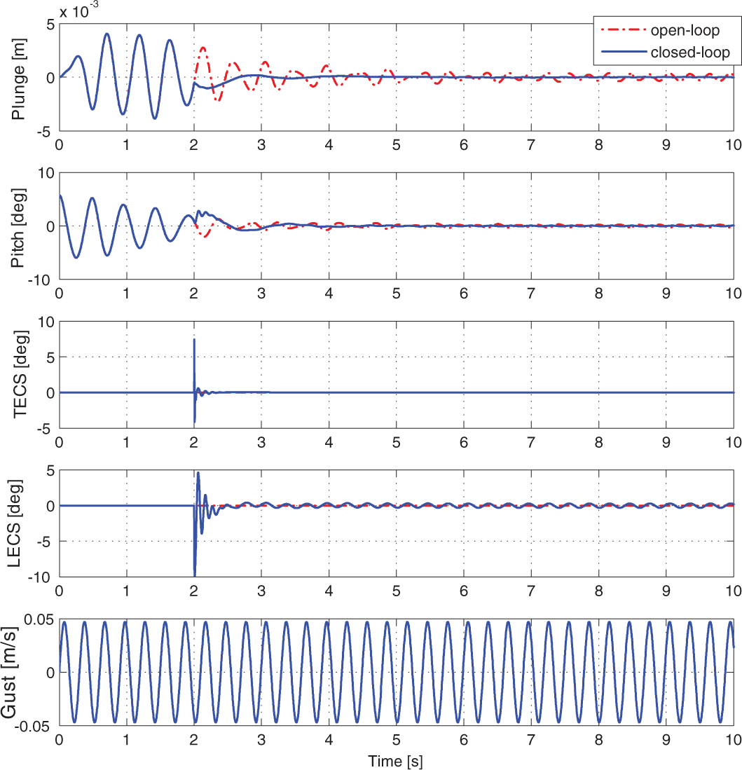
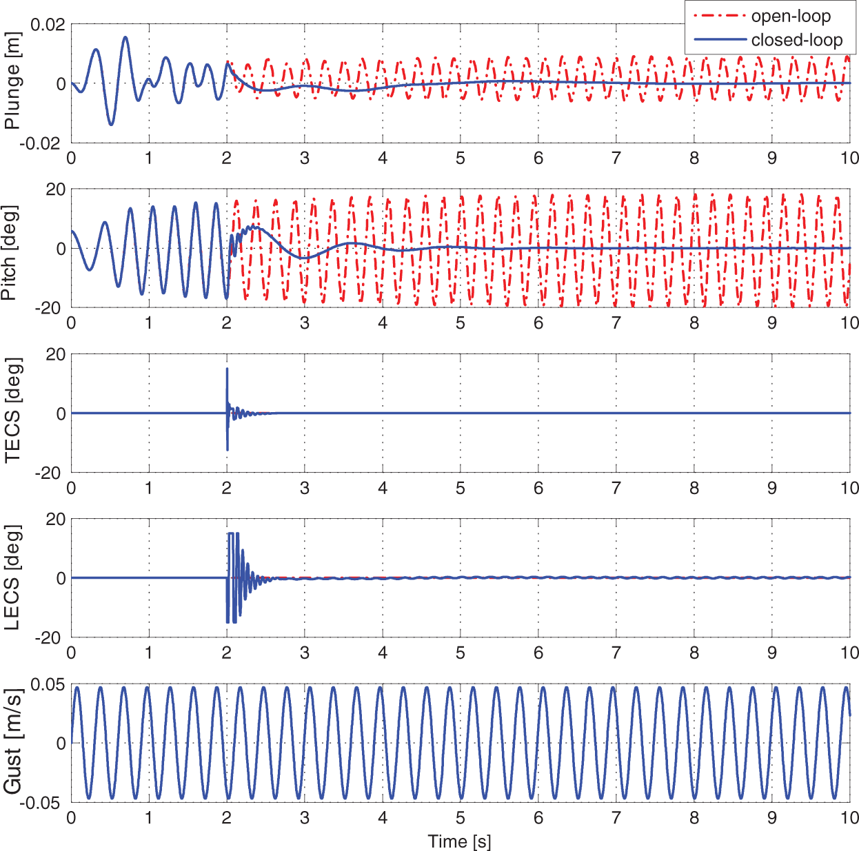
The last simulation set is for system response under sinusoidal disturbance. Figures 8 and 9 show the open- and closed-loop system response at both pre- and post-flutter speed under sinusoidal disturbance. The controller is turned on at . From Figure 8, one can see that the system keeps oscillating in open loop even at pre-flutter speed because of the sinusoidal disturbance. After the controller is turned on, the outputs h and α are stabilized in . At post-flutter speed, as shown in Figure 9, the open-loop system response is obviously coupled with the sinusoidal disturbance. However, the controller effectively stabilizes the system in As shown in Figures 8 and 9, due to the persistence of sinusoidal disturbance, there are still small residual oscillations in the response of β and Figure 5 in Wang et al. (2012) shows the system response under the same circumstance with a continuous robust control design. By comparison, one can find that the controller flaps deflections were saturated for over 1.5[s], in Wang et al. (2012) for this case. While in Figure 9 with new control design, we can see the saturation of LECS and TECS disappeared in less than 0.2[s]. Readers can also find that the system convergence time with the control design in this paper is much less than that of the continuous robust control design in Wang et al. (2012).
Open- and closed-loop system response under sinusoidal gust at pre-flutter speed [m/s].
Open- and closed-loop system response under sinusoidal gust at post-flutter speed [m/s].
6. Conclusions
In this paper, an output feedback robust control was proposed to suppress aeroelastic vibration of a wing section system operating in a quasi-steady aerodynamic incompressible flowfield. The leading-edge (LE) and trailing-edge (TE) control surfaces deflection were considered as the control inputs. Only the measurements of the pitching and plunging displacements were required for the control design, and a specific filter was built to substitute for the traditional state observer. That specific filter has a simple structure when compared with different kinds of state observers proposed in the literature, and is suitable for the case when little information is known about the plant structure and parameters. The robustness and efficacy of the controller was validated by simulation results under different operating conditions and disturbances. By comparing simulation results with previous literature, the new proposed control scheme was seen to achieve comparable or better performance with a simpler control design. A semi-global asymptotic stability result for the pitching and plunging displacements was guaranteed via a Lyapunov-based stability analysis.
Footnotes
Declaration of Conflicting Interests
The author(s) declared no potential conflicts of interest with respect to the research, authorship, and/or publication of this article.
Funding
The author(s) received no financial support for the research, authorship, and/or publication of this article.
Appendix A: Definitions of matrices and model parameters
References
1.
ArenaALacarbonaraWMarzoccaP (2013) Nonlinear aeroelastic formulation and postflutter analysis of flexible high-aspect-ratio wings. Journal of Aircraft50(6): 1748–1764.
2.
BaranyiP (2006) Output feedback control of two-dimensional aeroelastic system. Journal of Guidance, Control, and Dynamics29(3): 762–767.
3.
BehalARaoVMMarzoccaPet al.(2006) Adaptive control for a nonlinear wing section with multiple flaps. Journal of Guidance, Control and Dynamics29(3): 744–749.
4.
BhoirNSinghSN (2004) Output feedback nonlinear control of an aeroelastic system with unsteady aerodynamics. Aerospace Science and Technology8: 195–205.
5.
DowellEH (1978) A Modern Course in Aeroelasticity. Sijthoff and Noordhoff.
6.
Edwards JW (1977) Unsteady aerodynamic modeling and active aeroelastic control. PhD Thesis, Stanford University, USA.
7.
GangsaasDLyUNormanDC (1981) Practical gust load alleviation and flutter suppression control laws based on LQG methodology. AIAA Journal21.
8.
HorikawaHDowellEH (1979) An elementary explanation of the flutter mechanism with active feedback controls. Journal of Aircraft16(4): 225–232.
KarpelM (1982) Design for active flutter suppression and gust alleviation using state-space aeroelastic modeling. Journal of Aircraft19(3): 221–227.
11.
KhalilHK (1996) Nonlinear Systems, 3rd edition. Prentice Hall, pp. 323–324.
12.
KoJKurdilaAJStrganacTW (1997) Nonlinear control of a prototypical wing section with torsional nonlinearity. Journal of Guidance, Control, and Dynamics20(6): 1181–1189.
13.
KoJKurdilaAJStrganacTW (1999) Adaptive feedback linearization for the control of a typical wing section with structural nonlinearity. Nonlinear Dynamics18(3): 289–301.
14.
LazarausKCrawleyELinC (1995) Fundamental mechanisms of aeroelastic control with control surface and strain actuation. Journal of Guidance, Control, and Dynamics18(1): 10–17.
15.
LeeKWSinghSN (2007) Global robust control of an aeroelastic system using output feedback. Journal of Guidance, Control, and Dynamics30(1): 271–275.
16.
LeeKWSinghSN (2009) Immersion- and invariance-based adaptive control of a nonlinear aeroelastic system. Journal of Guidance, Control, and Dynamics32(4): 1100–1110.
17.
LeeKWSinghSN (2013) L1 adaptive control of a nonlinear aeroelastic system despite gust load. Journal of Sound and Vibration19(12): 1807–1821.
18.
LibrescuLNaSMarzoccaPet al.(2005) Active aeroelastic control of 2-D wing-flap systems operating in an incompressible flowfield and impacted by a blast pulse. Journal of Sound and Vibration283(3–5): 685–706.
19.
MarzoccaPLibrescuLChiocchiaG (2001) Aeroelastic response of a 2-D lifting surfaces to gust and arbitrary explosive loading signatures. International Journal of Impact Engineering25(1): 41–65.
20.
MarzoccaPLibrescuLChiocchiaG (2002) Aeroelasticity of two-dimensional lifting surfaces via indicial function approach. The Aeronautical Journal106(1056): 147–153.
21.
MarzoccaPLibrescuLSilvaWA (2004) Nonlinear open/closed-loop aeroelastic analysis of airfoils via volterra series. AIAA Journal42(4): 673–686.
22.
MorseAS (1993) A gain matrix decomposition and some of its applications. Systems and Control Letters21: 1–10.
23.
PatilMJHodgesDH (2002) Output feedback control of the nonlinear aeroelastic response of a slender wing. Journal of Guidance, Control, and Dynamics25(2): 302–308.
24.
PlatanitisGStrganacTW (2004) Control of a nonlinear wing section using leading- and trailing-edge surfaces. Journal of Guidance, Control, and Dynamics27(1): 52–58.
25.
PlatanitisGStrganacTW (2005) Suppression of control reversal using leading- and trailing-edge control surfaces. Journal of Guidance, Control, and Dynamics28(3): 452–460.
26.
ReddyKKChenJBehalAet al.(2007) Multi-Input/Multi-Output adaptive output feedback control design for aeroelastic vibration suppression. Journal of Guidance, Control, and Dynamics30(4): 1040–1048.
27.
SadeghNHorowitzR (1990) Stability and robustness analysis of a class of adaptive controllers for robotic manipulators. International Journal of Robotic Research9(3): 74–92.
28.
SimmonsG (1996) Calculus with Analytic Geometry, 2nd ed. New York, NY: McGraw-Hill, pp. 671.
29.
StrangG (1980) Linear Algebra and its Applications, 2nd ed. New York: Academic Press, Inc.
30.
Theodorsen T and Garrick IE (1942) Nonstationary flow about a wing-aileron-tab combination including aerodynamic balance. National Advisory Committee for Aeronautics NACA. Report, no. 736, pp. 137-138.
31.
VippermanJSClarkRLConnerMDet al.(1998) Investigation of the experimental active control of a typical section airfoil using a trailing edge flap. Journal of Aircraft35(2): 224–229.
32.
WangZBehalAMarzoccaP (2010) Adaptive and robust aeroelastic control of nonlinear lifting surfaces with single/multiple control surfaces: A review. International Journal of Aeronautical and Space Science11(4): 285–302.
33.
WangZBehalAMarzoccaP (2011) Model-free control design for MIMO aeroelastic system subject to external disturbance. Journal of Guidance, Control, and Dynamics34(2): 446–458.
34.
WangZBehalAMarzoccaP (2012) ) Continuous robust control for two-dimensional airfoils with leading- and trailing-edge flaps. Journal of Guidance, Control, and Dynamics35(2): 510–519.
35.
XianBDawsonDMQueirozMSet al.(2004) A continuous asymptotic tracking control strategy for uncertain nonlinear systems. IEEE Transactions on Automatic Control49(7): 1206–1211.
36.
XingWSinghSN (2000) Adaptive output feedback control of a nonlinear aeroelastic structure. Journal of Guidance, Control, and Dynamics23(6): 1109–1116.
37.
YuanYYuPLibrescuLet al.(2004) Aeroelasticity of time-delayed feedback control of two-dimensional supersonic lifting surfaces. Journal of Guidance Control and Dynamics27(5): 795–803.
38.
ZengYSinghSN (1998) Output feedback variable structure adaptive control of an aeroelastic system. Journal of Guidance, Control, and Dynamics21(6): 830–837.
39.
Zhang K (2015) Lyapunov-based robust and adaptive control design for nonlinear uncertain systems. PhD Thesis, University of Central Florida, USA.
40.
ZhangKBehalA (2014) Continuous robust control for aeroelastic vibration control of a 2-D airfoil under unsteady flow. Journal of Vibration and Control22(12): 2841–2860.
41.
ZhangRSinghSN (2001) Adaptive output feedback control of an aeroelastic system with unstructured uncertainties. Journal of Guidance, Control, and Dynamics24(3): 502–509.
42.
ZhangFSoffkerD (2009) Active flutter suppression of a nonlinear aeroelastic system using PI-observer. In: Motion and Vibration Control, Amsterdam: Springer, pp. 367–376.
43.
ZhangKMarzoccaPBehalA (2015a) Adaptive aeroelastic control of nonlinear airfoil with multiple flaps under unsteady flow. Journal of Vibration and Control. Ahead of print August 2015. doi:10.1177/1077546315597180.
44.
ZhangKWangZBehalAet al.(2012) A continuous robust control strategy for the active aeroelastic vibration suppression of supersonic lifting surfaces. International Journal of Aeronautical and Space Sciences13(2): 210–220.
45.
ZhangKWangZBehalAet al.(2013) Novel nonlinear control design for a two-dimensional airfoil under unsteady flow. Journal of Guidance, Control, and Dynamics36(6): 1681–1694.
46.
Zhang K, Wang Z and Behal A (2015b) A continuous asymptotic tracking control strategy for a class of uncertain MIMO nonlinear systems. In: 54th IEEE Conference on Decision and Control (CDC), Osaka, Japan, 15–18 December 2015, pp.6209–6214.