
Abstract
Real-time dynamic substructuring (RTDS) is a state-of-the-art experimental technique for evaluating the dynamic performance of a structural system subjected to time-varying loads in civil engineering. The accuracy and stability of RTDS is affected by the natural dynamics of the constituent transfer system. Of various control strategies, and due to the merits of simple implementation and low computational cost, delay-compensation methods have become most pervasive. In this paper, the performance of delay compensation based methods for RTDS is assessed in terms of accuracy and stability. Three commonly-used delay compensation schemes are considered, two of which are time variant and one time invariant. Stability is assessed analytically, numerically, and experimentally. Accuracy is assessed numerically and experimentally. To provide a suitable test for the delay compensation control schemes, a shaking table is adopted as the RTDS transfer system. It is demonstrated numerically, analytically, and experimentally that when applied to transfer systems such as these, delay compensation can work to the detriment of test accuracy and test stability. Adequate performance of delay compensated, shaking-table based RTDS is confined to a narrow low frequency bandwidth, which severely restricts the range of potential application.
Keywords
1. Introduction
In civil engineering, dynamic substructuring is an experimental method that fuses numerical modeling techniques with laboratory testing to evaluate the response of complex structural systems to dynamic loading (Nakata, 2011; Guo et al., 2014). The unpredictable component of the system—the substructure—is tested physically in the laboratory using a transfer system. The remainder of the structural system is consigned to a numerical model. The composite nature of dynamic substructuring systems allows critical structural components to be tested at full scale since laboratory apparatus are laden with neither the full mass nor the complete geometry of the emulated system. The dynamic substructuring method alleviates many of the shortcomings associated with conventional test techniques (Nakashima, 2001; Williams and Blakeborough, 2001).
The block diagram displayed in Figure 1 indicates the relationships between the principle components of the real-time dynamic substructuring (RTDS) system shown in Figure 2. More details can be found in the study by Tang et al. (2017). (Ignore for the time being the “stop” block.) Implementation generally involves two control loops. The outer loop calculates the required displacement response (yN) of the numerical–physical interface by summing the effect of the reference excitation (d) on the numerical model (GNd) and the effect of the reaction force (f) feeding back from the physical substructure (GP) on the interfacial constraint (GNf). In addition, an inner control loop is required to counteract the inherent dynamics of the transfer system (Gts) that can otherwise be ruinous to RTDS performance (Nakashima et al., 1992). The intention of any RTDS test is to reproduce the response of a system as if it were being tested not as a collection of composite parts but in its entirety.
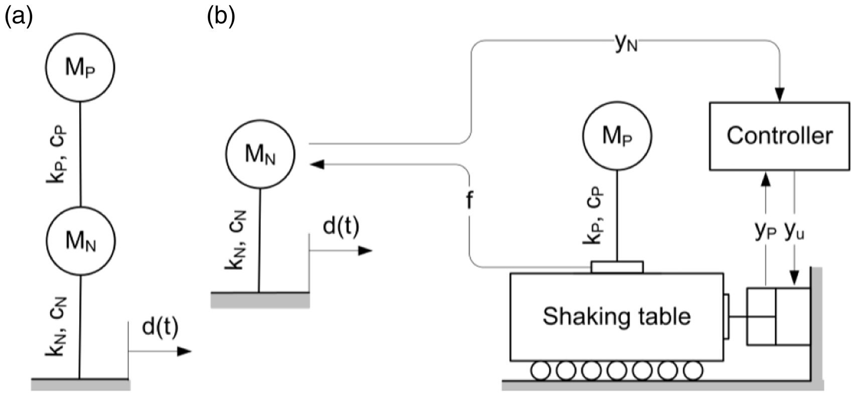
Generalized RTDS system. Shaking table RTDS: (a) emulated system; (b) RTDS system.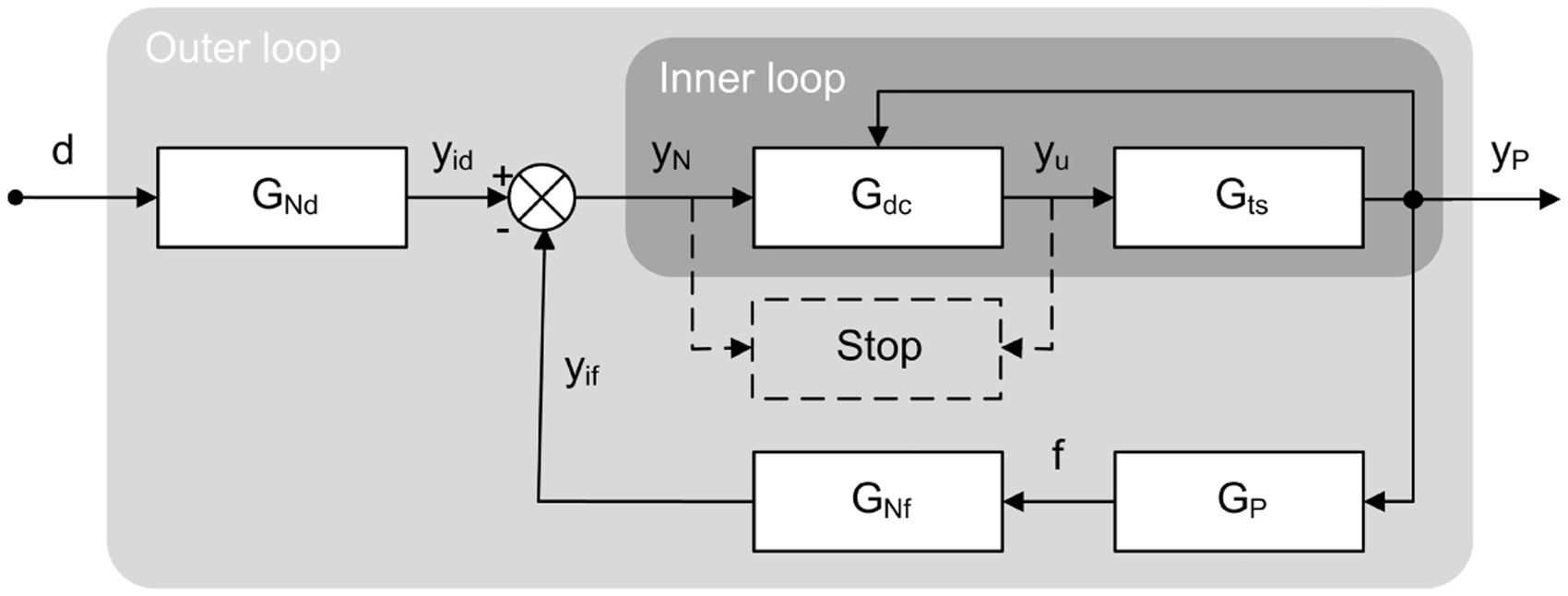
Advancement of the RTDS method has predominantly been focused towards implementing and improving inner-loop control so that dynamic loads are applied to the physical substructure correctly (e.g., Christenson et al., 2008). Two types of control methodology have been adopted: one based on classical control theory (Guo et al., 2016; Yao et al., 2016), the other based on delay compensation (Wallace et al., 2005a; Wang et al., 2011). These can be looked upon as forming different species within the RTDS genus. The simple implementation and low computational cost of delay compensation has garnered much favor and allowed it to become prominent amongst the alternative RTDS control schemes. As such, the inner loop controller of Figure 1 is given the subscript dc.
Delay compensation works to counteract the natural delay inherent in the RTDS system due to the inability of a transfer system to respond instantaneously to a change in state as prescribed by a numerical model. If not compensated, this delay adds negative damping to the RTDS system causing poor accuracy and instability (Horiuchi et al., 1999). At the core of delay compensation is the concept that the following expression is sufficient to characterize the dynamics of the transfer system

The displacement achieved by the transfer system (yP) is equivalent to the desired displacement (yN) delayed by τ seconds. Thus, by extrapolating yN forward in time by an amount equivalent to τ and using the predicted values to drive the transfer system, the adverse effect of transfer system dynamics on RTDS performance are negated. On this basis, numerous formulations of delay compensation have been proposed (Wallace et al., 2005a; Wang et al., 2011). A common feature of all these methodologies is that the dynamics of the included transfer system have to satisfy the unit-gain, linear-phase assumptions inherent in delay compensation.
When using the standalone servo-hydraulic actuators as the reference transfer system (Gawthrop et al., 2007; Carrion et al., 2009), the unit-gain, linear-phase assumptions can be met in the low frequency band. In this frequency range, delay compensation based strategies supplied a satisfactory performance for RTDS (Chen and Ricles, 2009). However, when the testing capability is required in the high frequency band, the performance of the delay compensated RTDS is unknown. Moreover, while standalone-actuator RTDS certainly extends testing capabilities, it also places restrictions on the form of the substructures that can be tested. To allow the testing of substructures with distributed properties (mass or geometry), attempts have been made to extend RTDS to incorporate transfer systems of increased sophistication such as shaking tables (e.g., Shao et al., 2009). In shaking table RTDS, the use of delay compensation has also met with mixed success (Lee et al., 2007; Wang et al., 2016). However, the dynamic characteristics of such transfer systems differ from those of standalone actuators due to their increased complexity. Shaking tables, for instance, have significant inherent mass associated with the shaking table that will, in the least, work to increase the transfer system delay and magnitude error, a potential jeopardy to reliable forward extrapolation and, consequently, RTDS performance (Horiuchi et al., 1999). The challenge posed to delay compensation by shaking table transfer systems is severe.
Herein, a shaking-table transfer system is used to explore both analytically and experimentally the performance envelopes of three alternative formulations of delay compensation. Time variant and invariant methodologies are compared. Performance is assessed in terms of accuracy and stability using the time- and frequency-domain based methods developed within.
2. Alternative formulations of delay compensation
In their pioneering studies, Horiuchi et al. (1999) and Horiuchi and Konno (2001) compensated for delay by driving the transfer system using predicted future values of yN derived from current and past values. By extrapolating a predefined number of recorded yN points forward in time using a polynomial with predefined coefficients and a predefined order, a prediction of yN a single whole time step ahead of time was obtained. Here, the time step refers to that of the RTDS outer loop integration algorithm. The single time step compensation method will herein be referred to with the abbreviation SDC.
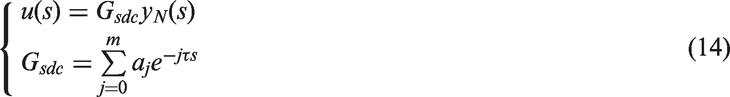
With m and ai the predefined order and coefficients of the polynomial, respectively, yN0 the present position of the interface, yN(t − iτ) former positions of the interface at prior time increments iτ, and τ the transfer system delay, the SDC command signal (yu) becomes

While the simplicity and speed of SDC are beneficial to RTDS implementation, its formulation based on predefined terms is restrictive. Performance is strongly dependent on the time step of the RTDS integration algorithm and is compromised when the time-step is close to or bigger than the system delay. Darby et al. (2001) refined the method using interpolation schemes to improve the accuracy of this scheme. Wallace et al. (2005b) removed some of the restrictions of SDC to produce a more generalized scheme wherein the prediction can be multiples or fractions of time steps and the constraint on the utilized number of previous yN points is removed. The Wallace et al. (2005b) multi-step prediction scheme will be referred to herein with the abbreviation MDC.
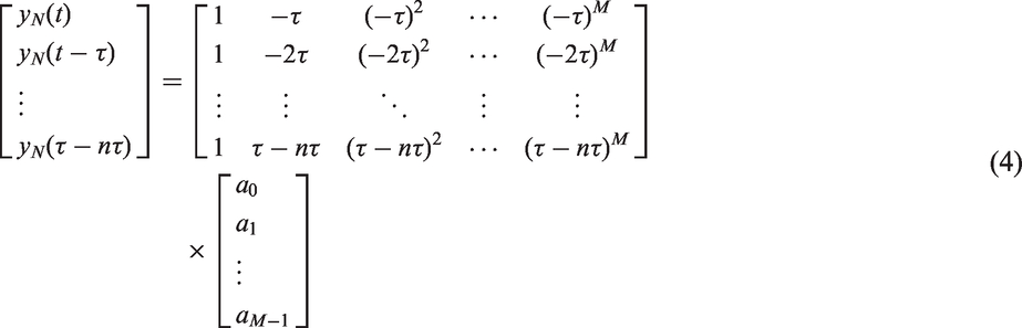
MDC works as follows. At each RTDS time step, a vector of the n most recent historic values of yN is constructed. An Mth order polynomial fit to the yN vector is constructed using the least squares method. The derived vector of polynomial coefficients (a) for the current time step provides the basis for forward extrapolation toward the predicted value used to drive the transfer system

In practice, actuator delay is related to both the dynamics of actuator and the time-variant characteristics the substructure. This has led to the development of adaptive schemes intended to deal with time varying delays. Darby et al. (2002) proposed an online method for estimating the delay as a RTDS test progresses through the product of the actuator position error and its velocity. The delay estimate for the ith time-step τi is given by

Other more recent implementations of delay compensation include the method developed by Ahmadizadeh et al. (2008) to measure the delay directly from desired and measured displacement histories during the progress of RTDS testing and the dual compensation schemes which combined delay compensation together with other control schemes (e.g., Chen and Tsai, 2013). However, the three aforementioned schemes (SDC, MDC, and ADC) are herein taken as the benchmarks that represent the key advancements within the ever-expanding field of delay compensation methodologies.
3. Analytical performance assessment
Analytical methods can be employed to achieve a better understanding of the factors affecting RTDS performance. Below, the adopted analytical methods are introduced and their output is presented and discussed. Stability and accuracy are considered in turn.
3.1. Delay compensated shaking table RTDS
The shaking table RTDS system of Figure 2 is adopted to provide a preliminary assessment of delay-compensation performance. The uppermost degree-of-freedom is taken to be the critical part of the system to be tested physically. Under the action of a reference excitation d(t), the shear force below the physical substructure is measured and fed back to the numerical model so that the translation of the physical-numerical interface can be derived. A shaking table is used to impart the interface translation to the physical substructure.
Given that mN, cN, and kN represent the mass, damping, and stiffness of the numerical model, mP, cP, and kP represent the mass, damping, and stiffness of the physical substructure, and referring back to Figure 1, the linear system transfer functions become


3.2. Stability
While the stability of time-invariant schemes such as SDC can efficiently be evaluated analytically in the frequency domain, time-variant schemes such as MDC and ADC require the use of numerical time-domain based methods. The adopted analytical methods will be introduced first.
Viewing the generalized RTDS system of Figure 1 as a closed loop feedback system provides a means for the stability assessment of linear (i.e., time-invariant) control schemes. The pertinent closed loop transfer function is

The stability of this expression can be analyzed using the root locus technique (Dorf and Bishop, 2008). The standard form of the root locus technique can be expressed as


Here K is the parameter that affects the stability of the system in the way to be determined and G(s) is a polynomial with constant values for the remaining system parameters. The roots locus technique tracks the migration of the poles of equation (10) about the s-plane as K is increased from zero to infinity. The critical stability point occurs at the value of K that renders pure imaginary roots.
To obtain an expression for Gts, a system identification of the six-axis shaking table was conducted using a 0.1–20 Hz sine sweep. Experimental results are displayed in Figure 3(a) alongside the fourth order transfer function of
Transfer system models: (a) shaking table; (b) standalone actuator.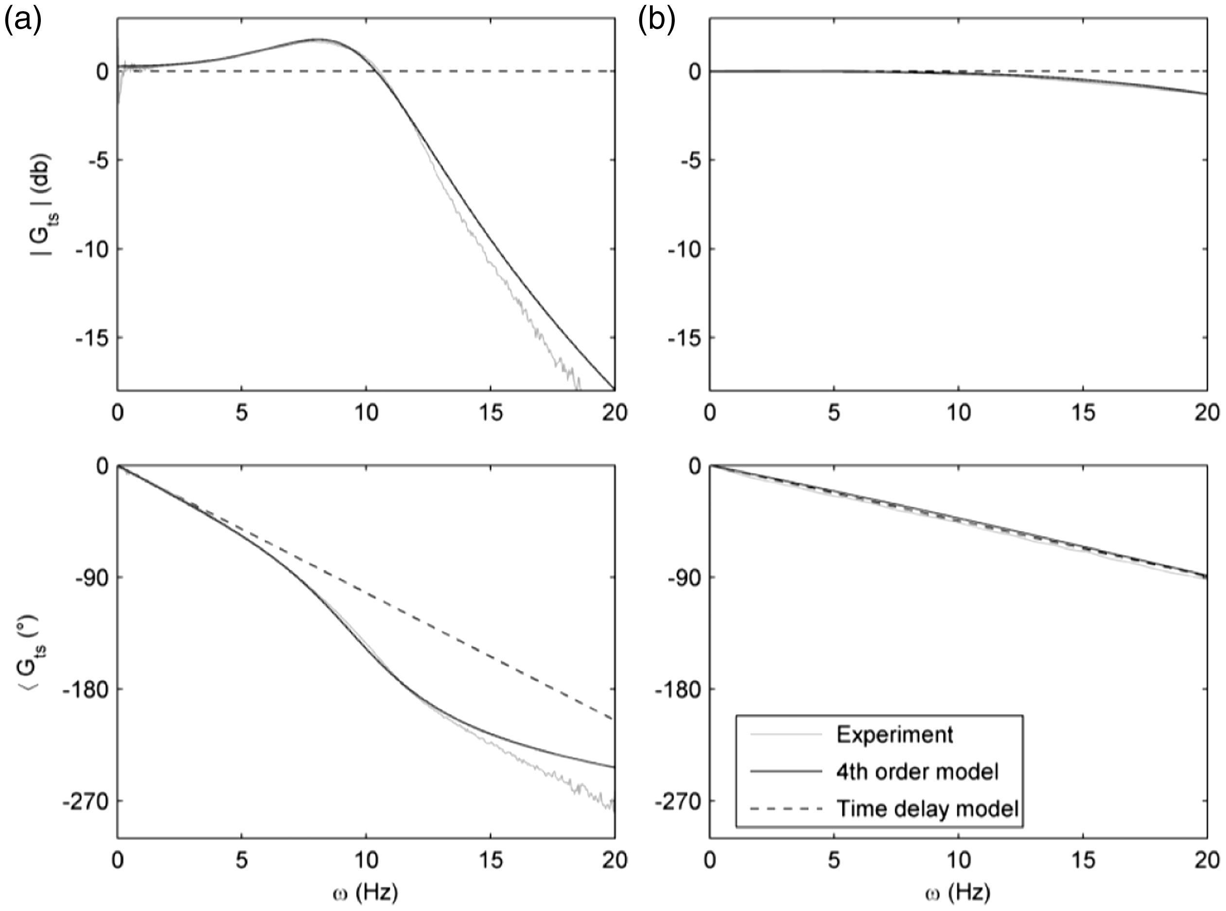

As an aside, the experimentally derived frequency response function for the Carrion et al. (2009) standalone-actuator based RTDS system is plotted in Figure 3(b) alongside the analytically derived transfer function of

Also presented are the frequency characteristics of the pertinent pure delay (τ = 9.4 ms) model.
While the fourth order models provide a reasonable fit to both sets of experimental data across the 20 Hz bandwidth, the quality of the fit associated with the time-delay model deteriorates from 10 Hz for the standalone actuator transfer system and from 2 Hz for the shaking table transfer system. The reduced bandwidth of the time delay model of the shaking table transfer system is a result of the mass of the seismic platform lowering the resonant frequency of the transfer system (to about 10 Hz as shown in equation (12)) compared to that of the standalone actuator (about 25 Hz as shown in equation (13)).
To obtain an expression for Gdc for the time-invariant SDC control scheme the Padé approximation (Golub and Loan, 1996) is used to rationalize the transfer function of equation (2). Given
With expressions for Gsdc and Gts defined, and the transfer functions of the substructure and interfacial restraint available as equations (7) and (8) respectively, equation (10) becomes

Here, ωN, ξN, ωP, and ξP are the natural frequency and damping ratio of the numerical model and substructure respectively and the physical-to-numerical mass ratio (σ) is taken to be the criterion by which the stability of the RTDS system is assessed. For the sake of presentation, in order to limit the range of parametric variation, the mass ratio σ is defined as

The stability of the inherently nonlinear RTDS systems featuring time-variant delay compensation cannot be assessed using the classical methods (i.e., root locus, Nyquist). Instead stability assessments for MDC and ADC were obtained via numerical simulations of the entire RTDS system using an appropriate SIMULINK/MATLAB model. MDC was used to compensate for a constant (28.5 ms) delay while, within the implementation of ADC, the time-varying delay evaluated by equation (5) was compensated for by MDC. Based on the research reported by Wallace et al. (2005b), a 25th order polynomial was used and Cv was set to 3. El Centro was used as a benchmark reference excitation.
The critical stability point of the MDC- and ADC-controlled RTDS system was derived numerically by conducting a series of successive simulations with incrementally increasing the mass ratio with the interval of 0.01. The onset of instability was defined as when the command signal (yu) exceeded the desired displacement by a factor of 10, at which point the simulation was halted via a “stop” block (the dashed lines in Figure 1). The mass ratio corresponding to the last successful simulation was designated as the critical stability point. To provide a comparison, the stability of the RTDS system without delay compensation (NDC) was also analyzed (using both the root locus technique and the time domain methods which gave equivalent results).
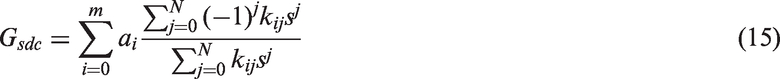
Three case studies at different damping levels of 2%, 5%, and 20% were chosen to represent a steel structure, a concrete structure, and soil-structure-interaction system, respectively. For each case study, the frequency response of the physical substructure and the numerical model were made congruent (i.e., ωP = ωN = ω and ξP = ξN = ξ), the damping was held constant and the frequency was increased (between 0.1 Hz to 10 Hz with 0.1 Hz interval). The derived critical stability lines which demark the stable (bottom left) from the unstable (top right) region are presented in Figure 4.
Stability boundaries of delay compensated RTDS: (a) ξ = 2%; (b) ξ = 5%; (c) ξ = 20%.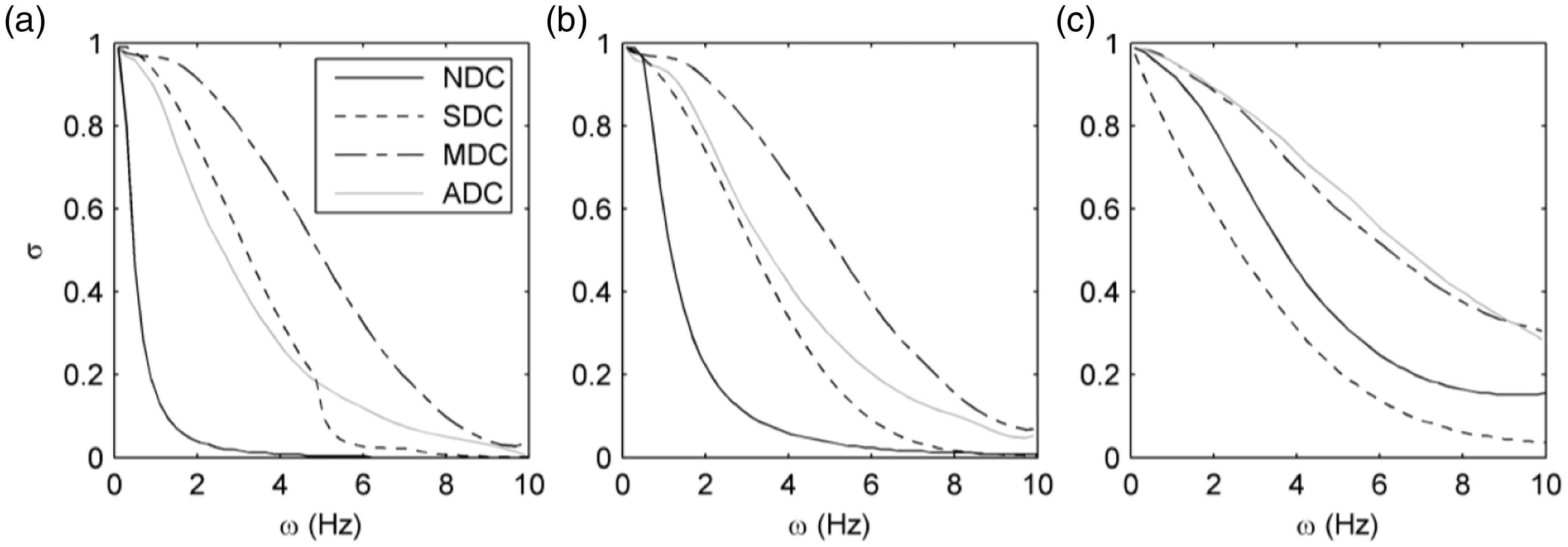
For each control scheme, the general trend is for RTDS stability to increase with ξ and decrease with ω. Compared to the NDC case, delay compensation generally enhances the stability and to a degree that lessens as the damping increases. The exception is for the SDC-controller that degrades the stability at high damping levels. MDC offers the most consistent performance and amongst the highest stability boundaries. While delay compensation is clearly capable of enhancing RTDS stability, the augmentation is generally not in the anticipated sequence (i.e., from NDC, through SDC and MDC to ADC).
3.3. Accuracy
An unabridged representation of RTDS accuracy can be obtained by considering test errors. An error measurement compounded by both magnitude and phase deviations can be generated by dividing local maxima of the absolute error (| yP – yN |) by local maxima of the sine-sweep reference excitation (|d|). The resulting “localized compound error” (LCE) is presented for each control scheme in Figure 5. Below 3 Hz, SDC provides optimal accuracy but errors grow quickly above this frequency. ADC and MDC work to keep errors lower across a wider bandwidth but exhibit a rapid loss of accuracy from around 5 Hz. Of the two, ADC provides better accuracy within the 5 Hz frequency band.
The localized compound error of delay compensation.
With records of the desired (yN) and achieved (yp) displacement time histories available, magnitude and phase errors can be uncoupled using system identification tools to estimate the frequency response of the RTDS inner control loop. Bode plots for the alternative delay compensation strategies are presented in Figure 6. In such plots, an optimal frequency response would be associated with a magnitude of unity and phase of zero. Contrasting Figure 6 with Figure 5 it becomes apparent that LCE errors are minimized across the bandwidth in which delay compensation rectifies the NDC phase lag. Outside of this bandwidth, both magnitude and phase deviate from their optimal values. ADC offers the widest bandwidth yet is also characterized by a rapidly varying and magnitude errors.
Comparison of delay compensated shaking table accuracy in frequency domain.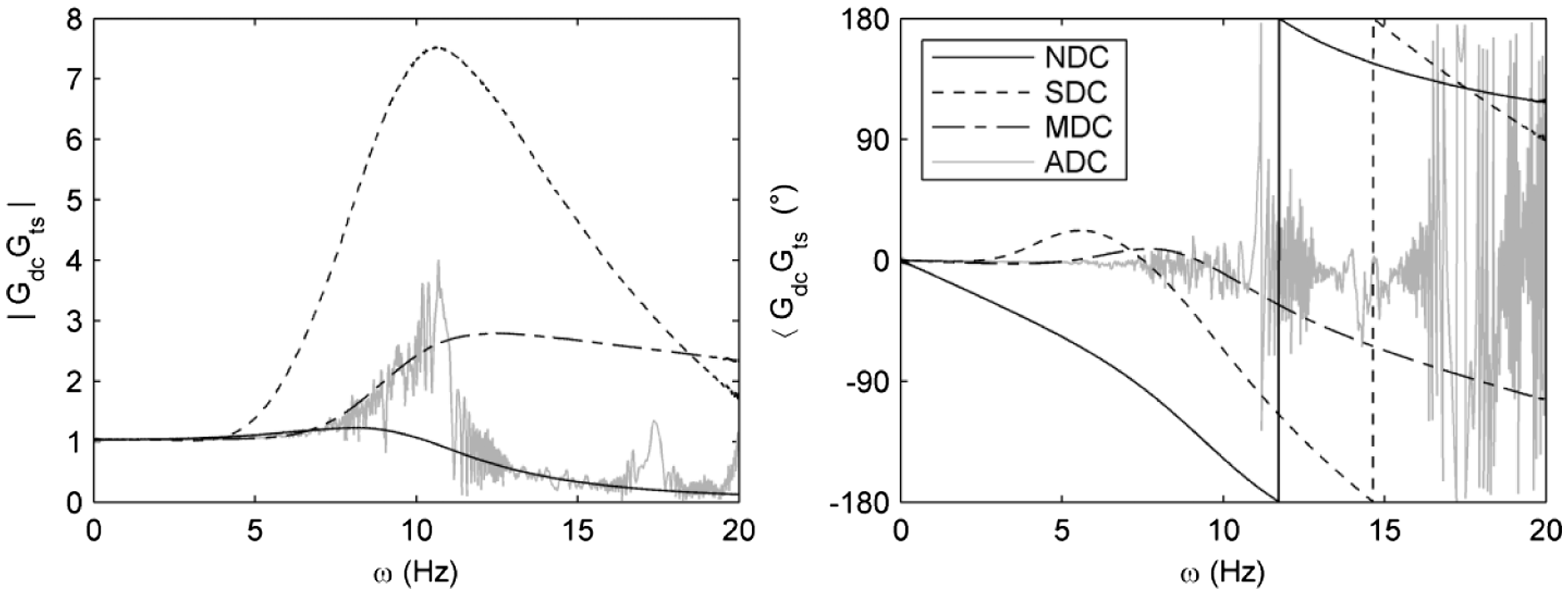
3.4. Discussion
Analytical results show that while delay compensation is capable of significantly enhancing RTDS stability, increased level-of-advancement of the utilized delay compensation methodology does not necessarily bring increased performance. Furthermore, with accuracy deteriorating rapidly at either 3 Hz or 5 Hz, delay compensation is found to augment transfer system dynamics across a curtailed bandwidth, restricting the range of potential application. Factors contributing toward the loss of performance are discussed below.
The belief that transfer-system delay has a dominating influence on RTDS performance (Horiuchi et al., 1999; Horiuchi and Konno, 2001) is born on the understanding that the magnitude error is near to zero and that the phase lag is proportional to the frequency of excitation. While this may be reasonable (across typical testing bandwidths) for standalone actuators, the dynamics of shaking tables meet these conditions within only a narrow frequency band (Figure 3). Outside of this frequency band, the divergence between y
N
and y
P
is a combination of both magnitude and phase deviations. Delay compensation schemes unable to distinguish between these different sources of error malfunction and impose additional phase and magnitude errors. Delay compensation works only when its underlying assumptions are met. To emphasize this point, the phase relationship for the shaking-table transfer system (obtained thorough equation (12)) is converted to a delay (τts) for comparison with the ADC delay estimate (τADC) in Figure 7. In the figure, |Gts| has been superimposed using a secondary axis. As |Gts| grows, so does the discrepancy between τADC and τts. ADC provides a poor estimate of the delay in the presence of transfer system magnitude deviation.
The ADC delay estimate.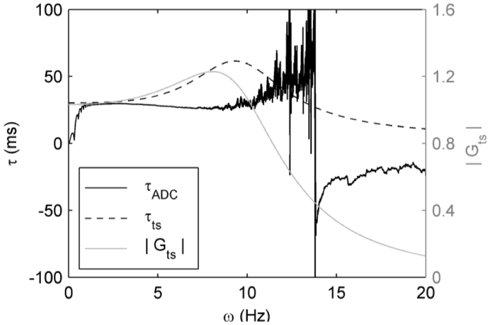
In previous studies, RTDS performance assessment has typically been conducted using single degree of freedom (SDOF) systems wherein the physical substructure constitutes a single system parameter (e.g., a spring or a damper). Herein, the RTDS system is a multi-degree of freedom (MDOF) system. The difference of the delay compensated SDOF- and MDO-RTDS stability can be explored using the Nyquist stability criterion (Golub and Loan, 1996).
With reference to the characteristic of equation (9), the critical frequency ωc and phase margin in terms of phase angle can be defined, respectively, as


The phase margin provides a measure of how near to instability the RTDS system is in terms of how much additional phase lag is permissible before stability is lost. Control theory asserts that the terms contained within these expressions can be grouped into convenient couplets:


The magnitude and phase characteristics of the GdcGts and the GNfGP couplets are displayed in Figure 6 and Figure 8, respectively. Unlike the SDOF systems that have been used to assess the stability of standalone-actuator based RTDS and having a single critical point (ωc), Figure 8 indicates that the RTDS system considered herein has two critical points (ω1, ω2). Each of these has the potential to cause instability. When the phase lead of GdcGts couplet at ω1 exceeds φ1 or when its phase lag at ω2 exceeds φ2, instability occurs. In the NDC-controlled RTDS system, the GdcGts couplet provides only phase lag. As a result, it adds to φ1 and subtracts from φ2. Hence, it is the magnitude of φ2 that determines the system stability. In SDC- and MDC-controlled systems, the phase lag of the GdcGts couplet is smaller and a phase lead is also apparent. Hence, the magnitude of φ1 may be the determinant of system stability.
Frequency response of the GNf GP couplet: (a) magnitude; (b) phase.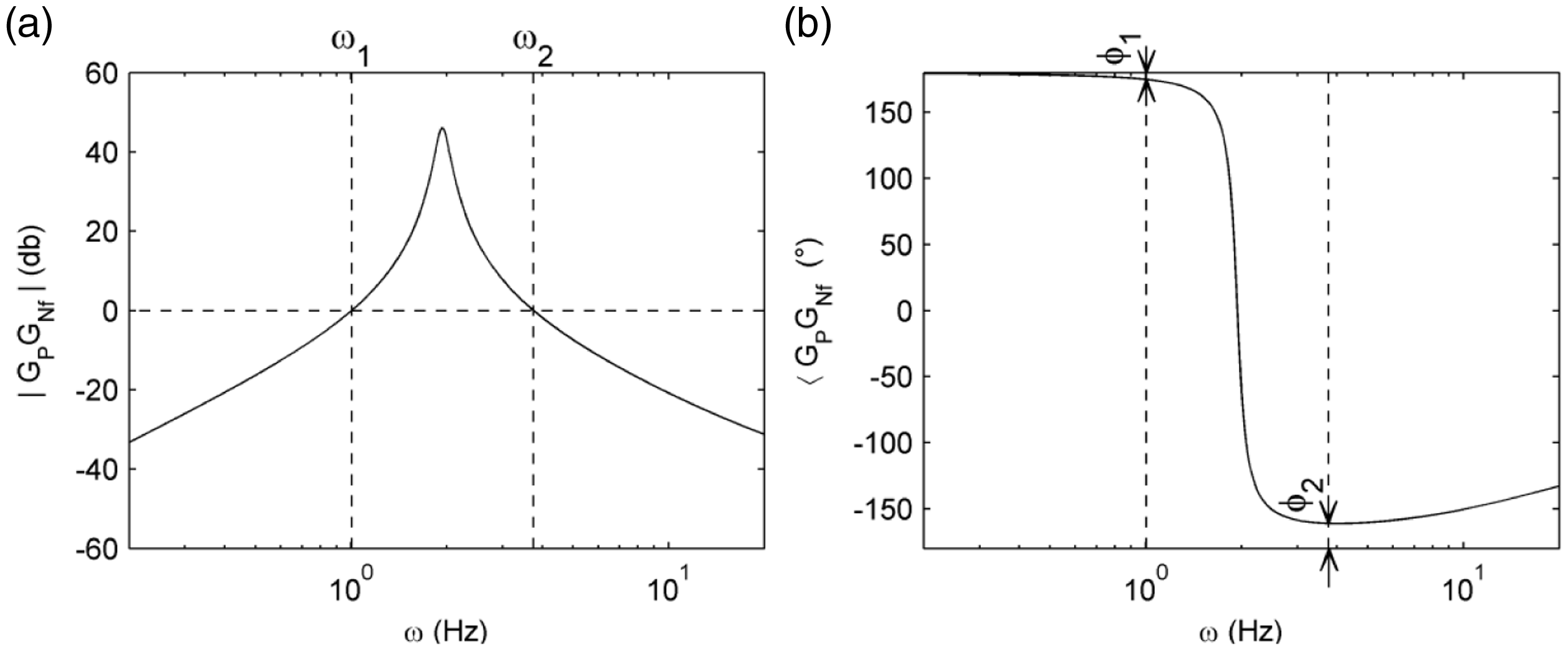
4. Experimental performance assessment
The substructure, pictured in Figure 9, consisted of a lumped mass a system of springs. The guide rails were supported on a rigid frame secured to a force plate which, in turn, was secured to the platform of the shaking table. The six axis force plate was configured to feedback the horizontal shear force between the substructure and transfer system. The substructure was configured to provide ωP = 1.94 Hz, ξP = 2.5%, and mp = 55.76 kg.
The authentic RTDS substructure.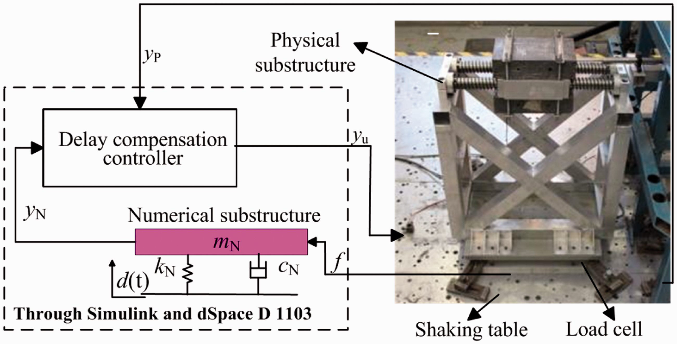
The damping ratio of the numerical model (ξN) was held constant at either 2% or 10%. The frequency of the numerical model (ωN) was taken as an experimental variable with magnitude to be incremented at 2 Hz intervals between 1 Hz and 9 Hz. El Centro was adopted as the reference excitation.
Figure 10 presents the experimentally measured stable and unstable points together with the analytical stability boundaries. While the experimental-analytical correlation is not as satisfying as that for the ancillary system, presumably a result of the presence of experimental uncertainties, the data points correspond reasonably well with the analytical prediction.
Stability of the authentic RTDS system: (a) ξN = 2%; (b) ξN = 10%.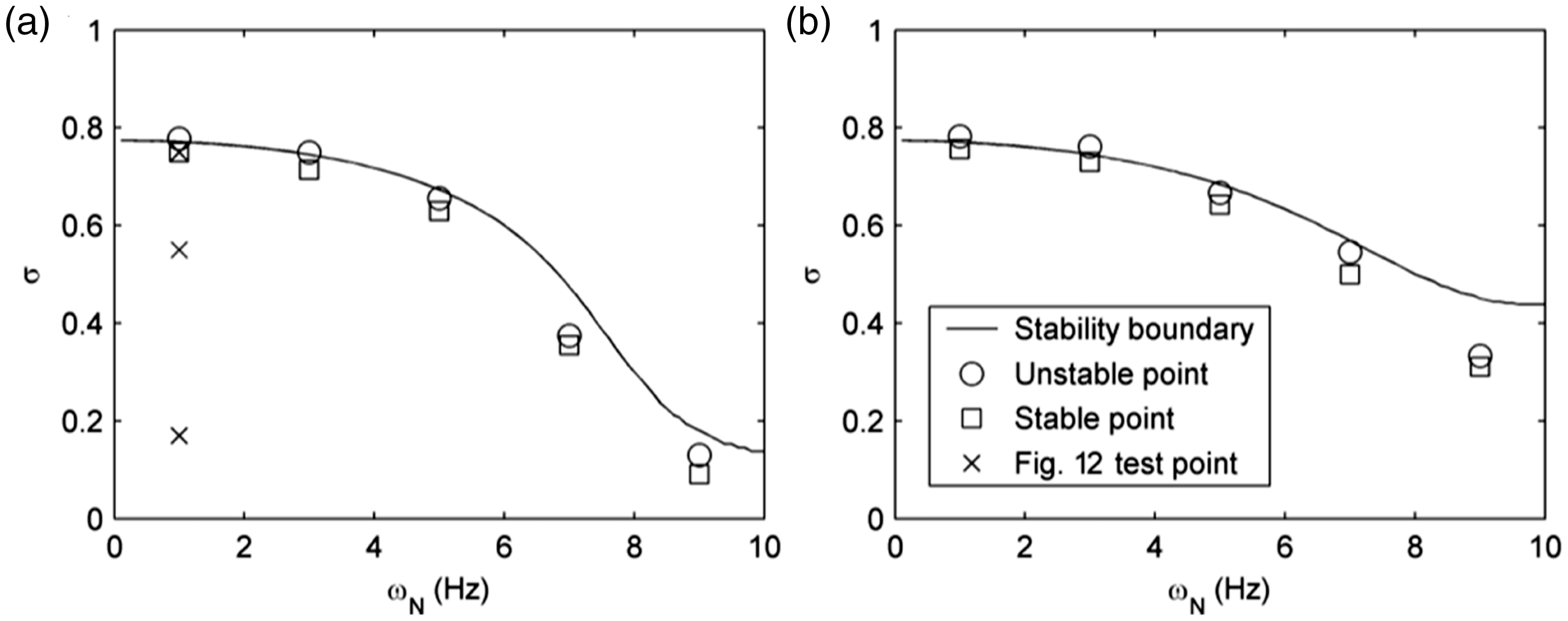
To assess the relative accuracy of the alternative delay compensation methodologies, an identical RTDS test (ωP = 1.94 Hz, ξP = 2.5%, σ = 0.2) was conducted using each of SDC, MDC and ADC. Results are presented in Figure 11. Figure 11(a) presents the pertinent subspace synchronization plots in which an equivalent level of accuracy is seen for each delay compensation scheme.
Representations of accuracy of the authentic RTDS system: (a) subspace synchronization, (i) SDC, (ii) MDC, (iii) ADC; (b) bode plot, (i) magnitude, (ii) phase; (c) ISE.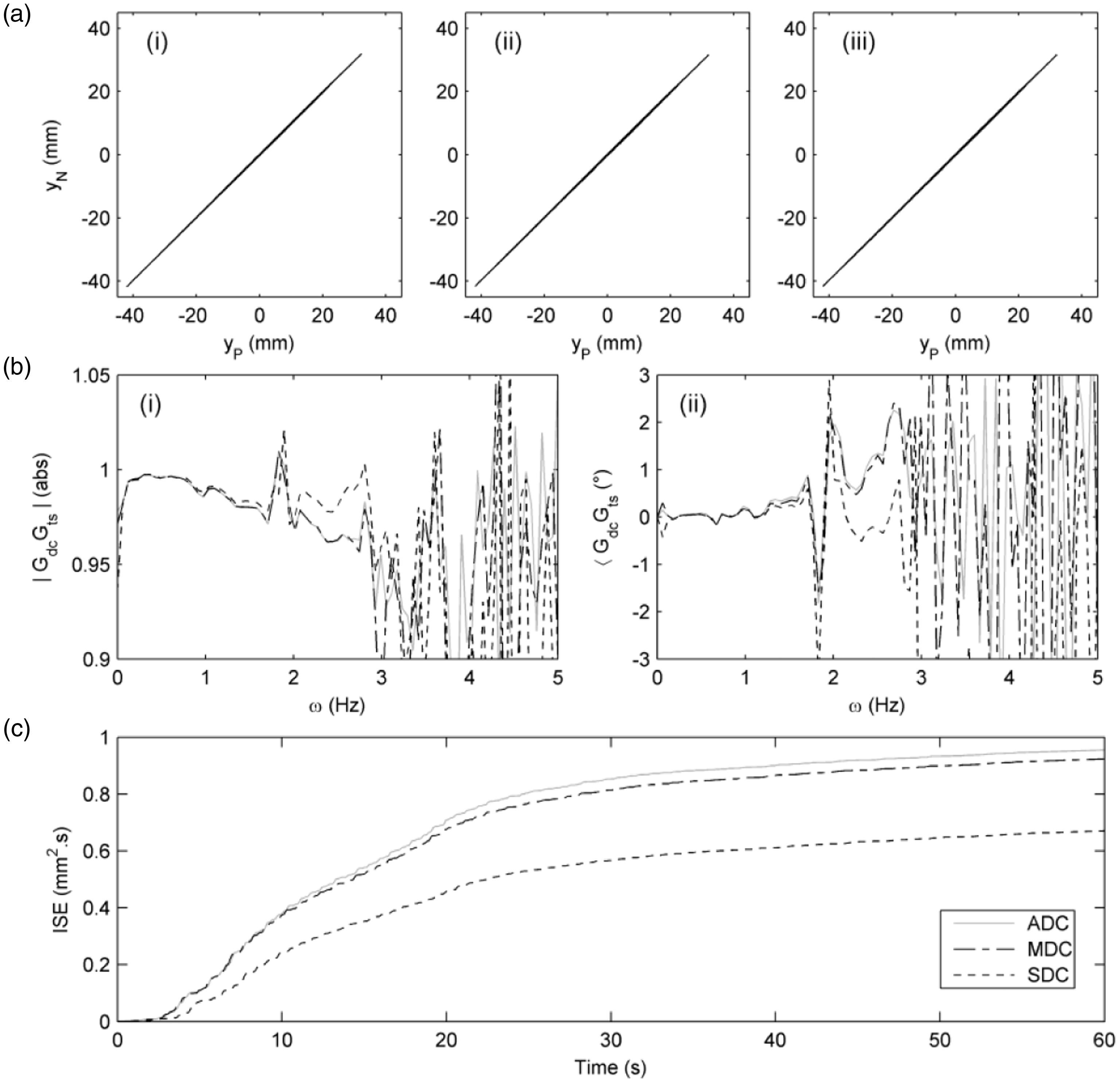
To distinguish between the schemes, bode and integral square error (ISE) plots are presented in Figure 11(b) and Figure 11(c), respectively. ISE is defined by

With the lowest rate of increase and magnitude of ISE error, SDC provides the optimal accuracy. ISE errors of MDC and ADC are significantly higher due to a worse performance in the 2–3 Hz band, consistent with the analytical results presented in Figure 5. Finally, the effect on accuracy of stability boundary proximity is assessed by conducting three equivalent tests (ωN = 1 Hz; ξN = 2.5%) using the SDC controlled RTDS system at different mass ratios (σ = 0.17, 0.55, and 0.75). The utilized test points are plotted (as crosses) in Figure 10 illustrating the wide range of testing and the close proximity of the uppermost test point to the stability boundary. Results are presented in Figure 12. Increasing mass ratio perceivably foreshortens the RTDS bandwidth and increases the measured ISE error. However, in synchronization subspace performance is seen to be little affected by mass ratio; the effect of stability margin on RTDS accuracy is small.
The effect of stability boundary proximity on RTDS accuracy: (a) subspace synchronization, (i) σ = 0.17, (ii) σ = 0.55, (iii) σ = 0.75; (b) bode plot, (i) magnitude, (ii) phase; (c) ISE.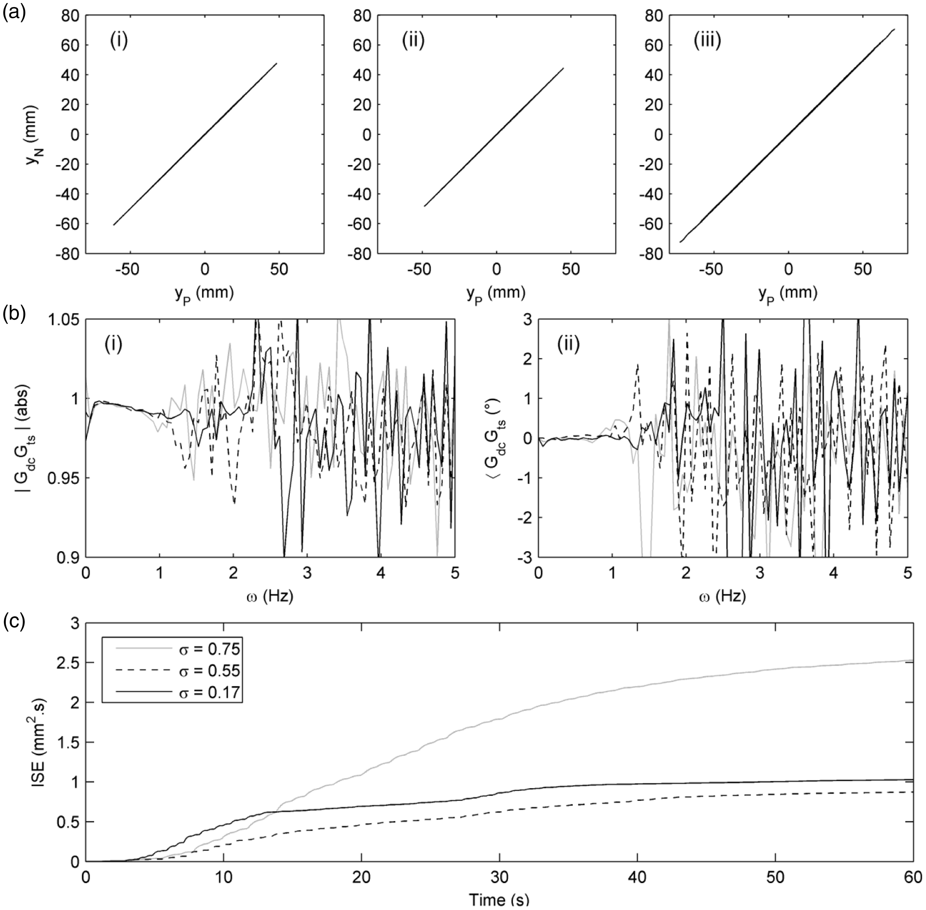
5. Conclusions
Herein, delay compensation is applied to shaking table based RTDS. Unlike standalone actuators, and due to the appreciable mass of the seismic platform, shaking tables have significant variation in their magnitude and phase characteristics across the test bandwidth.
RTDS stability is shown as being determined by the combined dynamical attributes of the system subcomponents in terms of both magnitude and phase: the substructure, the model, the delay compensator and the transfer system. Performance assessment should be attempted after properly accounting for the comprehensive dynamics integral to the RTDS system. Only then will the analytical and numerical methods presented within provide a reliable prediction of experimental response.
The performance enhancement associated with delay compensation is confined to a narrow, low-frequency band within which transfer system magnitude deviations are small. Accuracy and stability deteriorate rapidly as frequencies increase. The restricted bandwidth limits the range of potential applications of shaking table based RTDS.
It should be noted that while shaking-table based RTDS systems formed the basis of this study the presented conclusions are equally valid for other RTDS systems in which the dynamics of the included transfer system do not satisfy the unit-gain, linear-phase assumptions inherent in delay compensation.
Footnotes
Declaration of Conflicting Interests
The author(s) declared no potential conflicts of interest with respect to the research, authorship, and/or publication of this article.
Funding
The author(s) disclosed receipt of the following financial support for the research, authorship, and/or publication of this article: This work was supported by the NSFC (grant number 51608016), the Beijing NSFC (grant number 8164050), and the European Commission’s Seventh Framework Programme [FP7/2007-2013] (grant number 227887), Seismic Engineering Research Infrastructures for European Synergies (SERIES).