
Abstract
The paper aims to present the novel control structures for a drive system with an elastic connection. Two control structures based on forced dynamic control (FDC) laws are investigated. The first one is based on the state controller approach, the second one on cascade methodology. These two approaches ensure different dynamic properties of the drive system. In the first approach, called full-FDC, the ability to remove the effect of the load torque from the load speed is assured, but the shaft torque cannot be directly limited. In the second approach the possibility of fast elimination of the load torque effect is limited, yet the shaft torque can be fully controlled. The detailed design methodology of both control structures is presented in the paper. Their properties are analyzed through simulation and experimental studies.
1. Introduction
The present trend in industry is to produce lighter and cheaper components for different kinds of machines. This is usually achieved by reducing, when possible, their weight and size. However, the smaller size affects stiffness of mechanical parts. The increased flexibility can produce torsional vibrations in various parts of the machines. The torsional vibrations have been originally recognized in big industrial drives, such as rolling mill drives, lifting and conveyer drives and others (Hori et al., 1999; Zhang and Tong, 2006; Valenzuela et al., 2009). Nowadays they have become evident in modern high-performance drives, such as servo drives, robot arm drives or wind mill turbines (Montague et al., 2013; Bartschat et al., 2016; Wang et al., 2016; Yang et al., 2016; SoltanRezaee et al., 2018).
Such motion systems can be characterized by the following requirements. Firstly, torsional oscillations are not acceptable in modern systems because they affect the accuracy of speed/position control, precipitate the degradation of the mechanical parts, and can even be a reason for a sudden breakdown. Secondly, the selected control algorithm should allow to limit the maximal values of the system states. Those limitations are crucial in some industrial applications because their violation can damage the entire system (Montague et al., 2013; Wang et al., 2015, 2016). As for the electrical drive system, limitation of the drive torque and speed is not a problematic subject, yet including limitation of the shaft torque in the control algorithm is much less straightforward. The third common requirement for a motion control system is quick counteraction of the influence of the load toque on the speed of the controlled object. The industrial approach in this case is the implementation of the additional feedback from estimated load torque. However, this solution taken from the one-mass system (rigid body) is not effective enough in the case of flexibility.
The control structures used for suppressing vibrations in the two-mass system can be divided into two major groups. Definitely, the first one includes all systems based on linear control theory. In classical papers (Szabat and Orłowska-Kowalska, 2007) the system with a proportional–integral (PI)/proportional–integral–derivative controller with different poles-location is considered. It is shown that the damping ability of a standard PI controller can be improved by a suitable location of all closed-loop poles. However, this simple system is not effective and cannot supress oscillations effectively. The other approach is to use additional feedback(s) from one (or two) selected state variable(s) of the plant. Two feedbacks allow to locate all closed-loop poles in every desired position, which guarantees the desired performance of the plant (Szabat and Orłowska-Kowalska, 2007). The other approach popular in the literature is to analyze the system in the frequency domain. The paper by Hori et al. (1999), where the so-called resonance ratio controller is proposed, can serve as an example. The next control approach is based on the application of the state-space controllers (Zhang and Tong, 2006). Here the information of all state variables is necessary and it allows to locate the closed-loop poles in the desired position. The main problems mentioned here are: the selection of poles location (e.g., to make the system robust against parameter changes); or the choice of a suitable estimation technique. A quite new and promising control methodology is forced dynamic control (FDC) proposed by Professor S. Dodds (Vittek and Dodds, 2003; (Dodds and Szabat, 2006). However, in the two-mass system the resulting control law includes feedbacks from load torque and its derivatives, which is not easy to achieve in real-time application.
The second group of control approaches includes the following methodologies: adaptive control; sliding-mode control; predictive control; and other less popular techniques (Szabat and Orlowska-Kowalska, 2012; Kaminski and Orlowska-Kowlaska, 2013; Serkies and Szabat, 2013; Brock, 2014; Wang et al., 2015). The adaptive methodology is suggested to be used in the system with changeable parameters. As a controller, some intelligent algorithms can be implemented, for example, a fuzzy or ADALINE-based controller (Kaminski and Orlowska-Kowlaska, 2013). The nonlinear characteristic of the controller allows to achieve better performance than the linear one. There are a number of papers describing the usage of sliding-mode control in the two-mass system (Brock, 2014; Qiu et al., 2015). The main advantage of this methodology is robustness to parameter changes. The classical drawback is the chattering phenomenon, possibility of the steady-state error, and need for a relatively short sampling period. The model predictive control (MPC) has become very popular in the last decades in the area of electrical drives and power electronics. There are also works presenting its application to speed and position control of the two-mass system (Serkies and Szabat, 2013; Wang et al., 2015). The main advantage of MPC stems from the prediction of the behavior of the plant and selection of the optimal control signal on this basis. The control and variable constraints can be easily included into a cost function formulation.
Although the advanced control strategies possess many advantages, they are not popular in industry. More than 90% of industrial processes are controlled using solutions based on the linear control theory. This comes from the fact that those methodologies are easier to understand, they require less computational power, the tuning methodology is relatively simple, and the stability analysis is quite easy and intuitive.
There are two main goals of the paper. The first is to present the FDC design methodology for a two-mass system, which has not been published in any (to the authors' best knowledge) international journal. The performances of the structure are investigated under a variety of simulation and experimental studies. Then, secondly, a novel approach to the implementation of FDC to the two-mass system is proposed in the paper. Contrary to the first approach, the formulation of the control problem is divided into two steps. First, the shaft torque control loop is designed. The dynamics of this subsystem is set to be sufficiently fast. Then the algorithm for the speed control loop is implemented. Such configuration of the control loop allows to limit the shaft torque effectively.
2. Mathematical model of the plant
The mechanical torque transfer elements which connect the actuator (driving motor) with a working part are evident in many machines. In high-speed trains electric motors are connected through gearboxes to wheels. The force of the servo-motor is transmitted through a shaft to a load machine. In wind-turbines the blades are connected through the shaft and gearbox to a generator. In all these situations, in the mechanical part there can be distinguished specific numbers of rotating masses and shafts. In order to analyze such systems there is a need to select a suitable mathematical model which will accurately enough represent dynamics of the plant, and on the other hand allows to synthesize the control algorithm. Taking those two conditions into account, the so-called inertia-shaft-free model of the two-mass system is selected in the paper by Szabat and Orłowska-Kowalska (2007), which is described by the following state space model


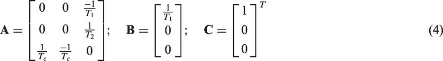

The mechanical part of the plant is described by the following three equations in the per unit system
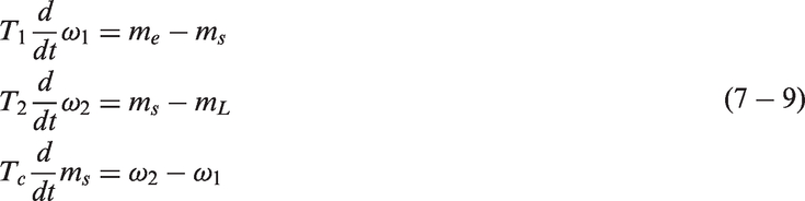
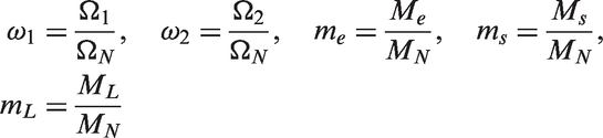
The schematic diagram of the mechanical model is presented in Figure 1.
Schematic diagram of the mechanical system.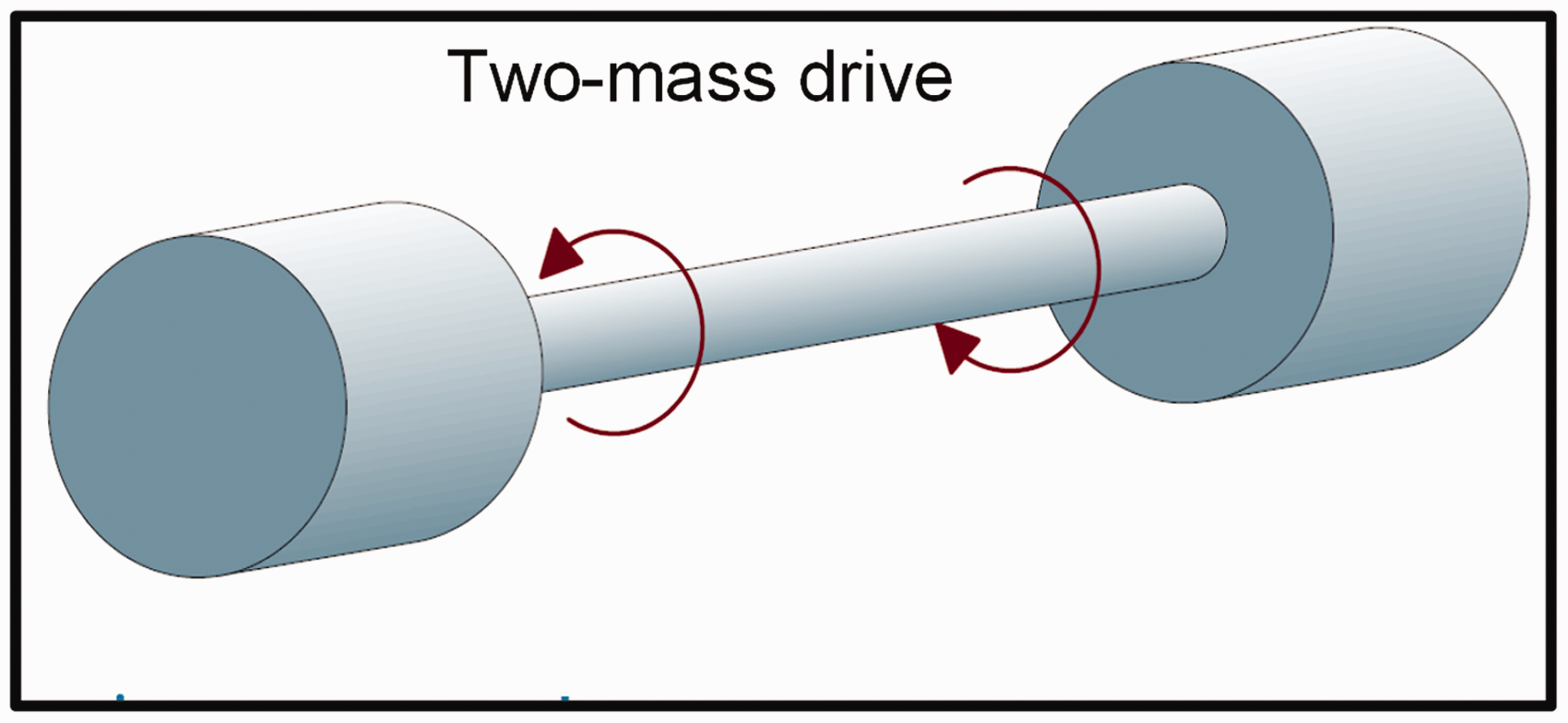
It should be mentioned here that the above-presented model is very popular in the literature. Also, if there is a need, it can be easily extended to a multi-mass model.
3. Control structures based on the FDC laws
3.1. Full FDC
In general, the control algorithm can be applied to any plant described by differential equations. The robustness of the structure is ensured by including into the control law the additional vector formulated by disturbances and its derivatives (if necessary). In practical applications these values have to be estimated.
In the first step the control goal should be formulated, which means that control and controlled variables must be specified. In the two-mass system the control variable is drive torque m
e
and in the controlled one load speed is ω
2
. The control law is obtained by multiple differentiation of equation (8) for the controlled output variable ω
2
, until the manipulated variable appears in the resulting equation. Thus


Because the control variable m
e
is not evident in equation (11), the process is repeated

Substituting for

Now the control variable m e appears in equation (13). This equation is called a controlled output derivative equation and will be used to design the control structure equation (8).
Next steps of design are similar to standard poles-placement methodology. There is a need to specify a desired polynomial. Because the system equation (13) is the third order, the polynomial can have the following form

Here, the closed loop system will be chosen to have all three poles of magnitude ω r , two being complex conjugates with a damping ratio of ξ and undamped natural frequency, ω r , to obtain a small overshoot in the step response if desired.
The desired closed loop differential equation corresponding to equation (14) is then

The FDC law is then obtained by equating the right-hand side of equations (13) and (15) and then making m
e
the subject of the resulting equation
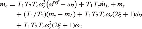
Then equation (16) can be rewritten as
Block diagram of full forced dynamic control (FDC)-based structure.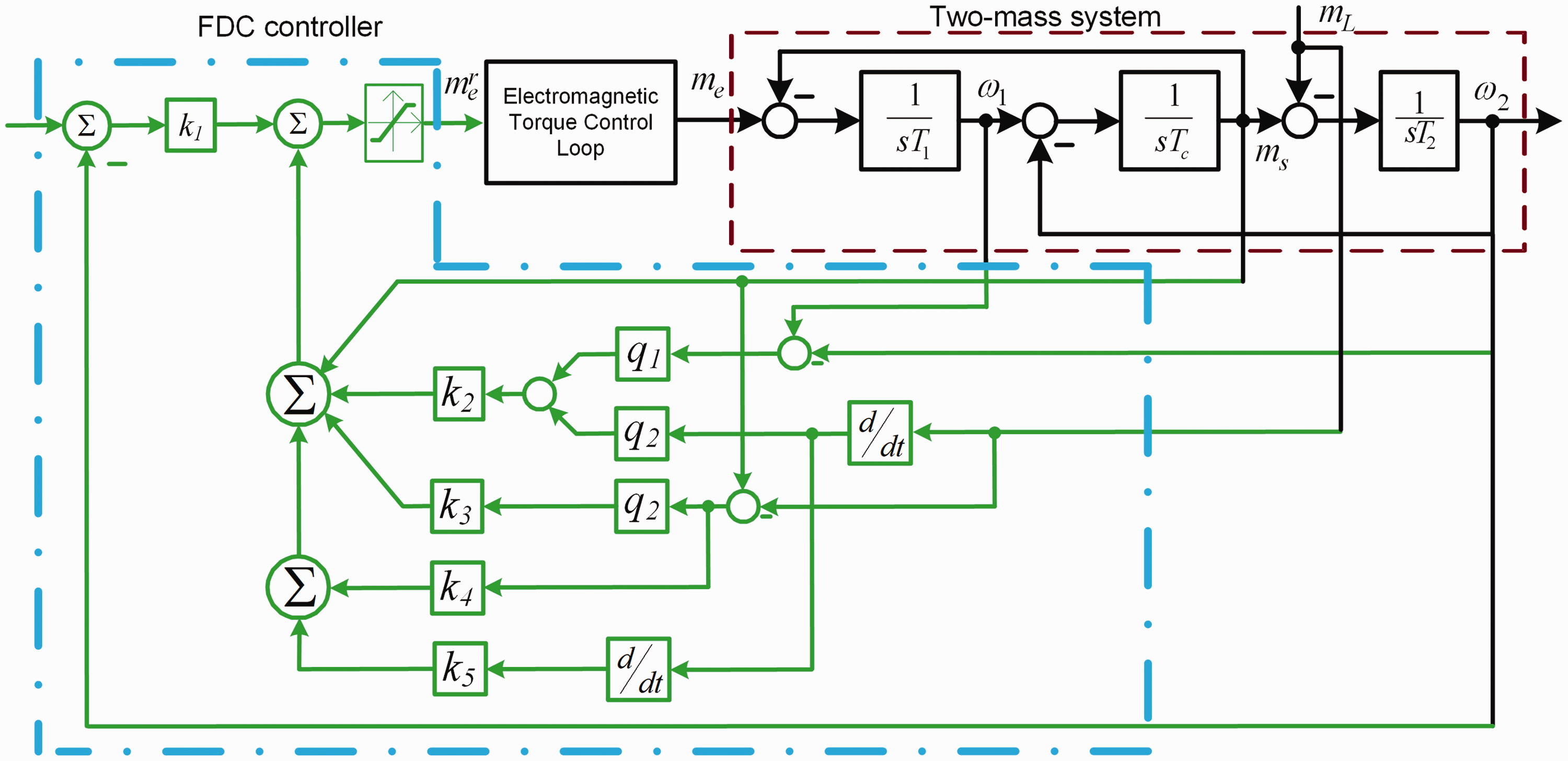


The control structure consists of three main elements: the optimized drive torque control loop (torque controller; power converter; and electromagnetic part of the motor, current/voltages sensor—it is assumed that the equivalent transfer function of this loop is equal to one, mechanical part of the drive (two-mass system), and speed control loop. It should be stressed again that the formulation of the control law requires the information of the load torque and its first and second derivatives, usually provided by some kind of estimator.
3.2. Cascaded FDC
The main drawbacks of the original FDC-based control structure are as follows: the necessity of estimation of the derivatives of the load torque; and the lack of the possibility of shaft torque limitation. Those two factors decrease the usefulness of the classical FDC control scheme. Therefore, in this subsection the design problem of the load speed control structure is divided into two steps. Firstly, the shaft torque control loop is analyzed. In the analyzed case the drive torque is a control variable, while the shaft torque is the controlled one. The FDC law is obtained by means of successive differentiations of equations, where the controlled variable is evident, while in the final equation the control variable appears. This process is presented below
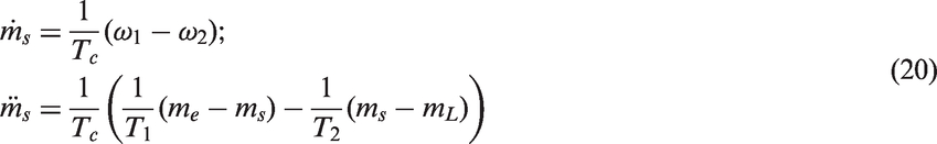
As can be seen in equation (20), the control and controlled variables are visible in this equation, hence the FDC control law will be specific for shaft torque regulation. The desired transfer function is presented below

The desired closed loop differential equation corresponding to equation (21) is then

The final FDC control can be formulate by comparison of equation (20) with equation (22) and setting the m
e
as a subject
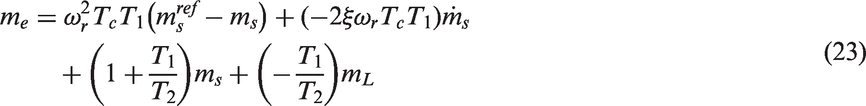
The derivative of the shaft torque evident in equation (23) can be removed by substituting of equation (9)

So far, the shaft torque control law has been designed. This variable can be controlled with freely set dynamics. Contrary to the full FDC control structure, the cascade control allows also to limit the maximal value of this variable.
In the next step the load speed control loop has been analyzed. The control structure encompasses the optimized shaft torque control loop and the load machine. If the set dynamics of the inner loop is much faster than the dynamics of the load speed control loop, then it can be neglected for further analysis.
Assuming that the dynamics of shaft torque control can be neglected, the speed FDC controller is obtained by analysis of equation (8)

The reference model is a first order term

Thus, the resulting equation can by formulated

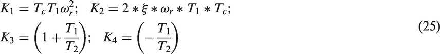
The designed control structure is shown in Figure 3.
Block diagram of cascade forced dynamic control-based structure.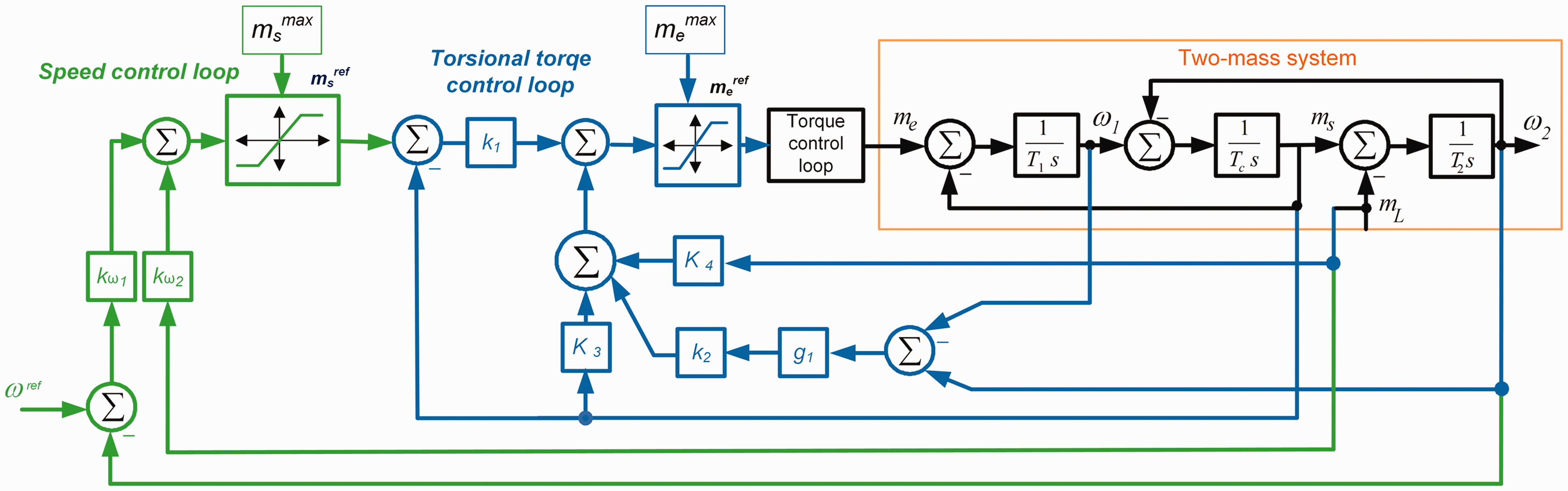
Due to the cascade concept the design procedure is much simpler. Additionally, there is a possibility to limit the drive and shaft torques directly. The FDC-based speed controllers can be replaced by a PI regulator. However, the FDC control law takes into account the internal feedbacks of the plant (from ω 2 ). The limits of drive torque result from the physical characteristics of the motor and power converter. The shaft torque limit comes from the used material and its geometry. In the simplest case those values are directly applied to the control structure. However, it should be stressed that this approach is not optimal, and in some cases can gain the torsional vibration which will be demonstrated in the next sections. So, more sophisticated methodology concerning the ratio of torque limits is needed.
4. Simulation study
In the simulation study the effectiveness of full and cascaded FDC-based control structures is investigated. In order to show the properties of the proposed control algorithm all signals needed for control are assumed to be accessible directly (a special estimator is used in the experimental study to provide them).
Firstly, the full FDC control structure (Figure 2) is tested. The influence of the design parameters on the dynamic properties of the drive is investigated. Two values of resonant frequencies are selected: ω
r
= 40 s−1 and ω
r
= 60 s−1; and damping coefficient ξ = 1. No limit for the control signal is assumed in this test. The reference value of the speed is set to 0.25. The transients of the system are presented in Figure 4.
Transients of the system variables: motor and load speeds (a, c); and drive torques and shaft torques (c, d) have a different value of the resonant frequency.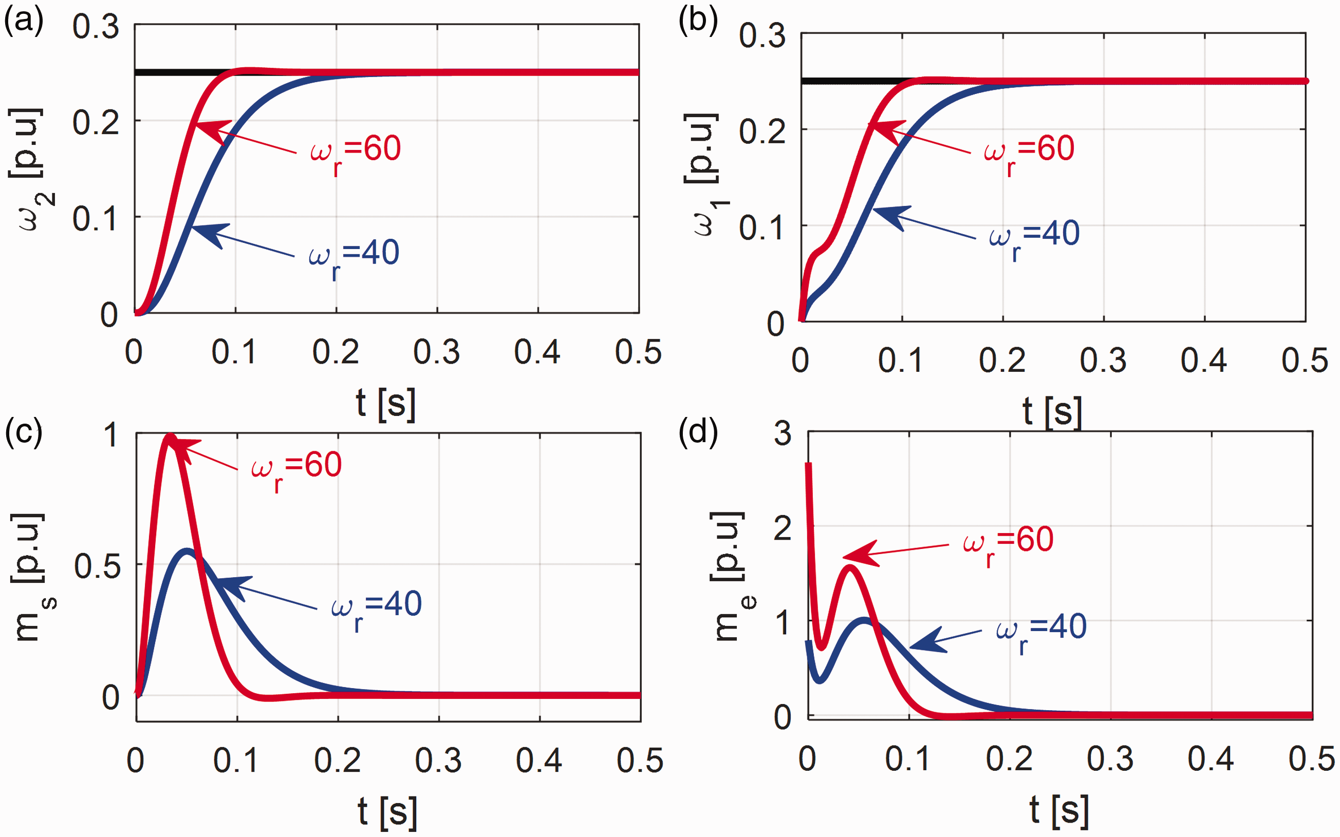
The following remarks can be formulated based on the analysis of the transients shown in Figure 4. The rising and setting time of the load speed depends on the design parameters. The bigger the resonant frequency, the faster dynamics is obtained. The system with the bigger value of the resonant frequency causes the more dynamical rise of system torques. Because closed-loop poles are located in real axis (ξ = 1) there is no overshoot in the output of the system. Decreasing the value of the damping coefficient causes overshoot in the load speed transient.
Then the ability of rejection of disturbances of the full-FDC structure is investigated. Two cases are considered here: a system with and without limitation of the drive torque. The transients of the states of the two-mass drive system are presented in Figure 5.
Transients of the system variables: motor and load speeds (a, c), drive torques, shaft torques, and load torques (b, d) for the system without (a, b); and with (c, d) limitation of the drive torque.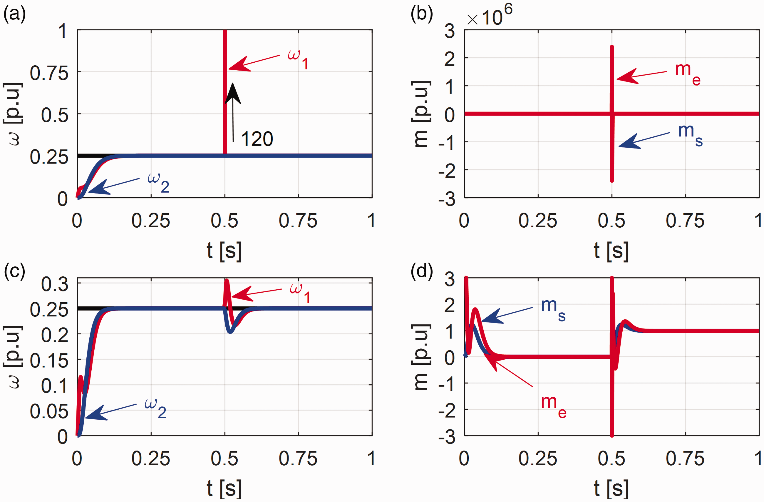
The transients of the system without limitation of drive torque are presented in Figure 5 (a) Figure 5 (b). The shape of the load speeds results from the set dynamics. At the time t = 0.5 seconds the load torque is applied to the system. No effect is visible in the load speed state, which means that the system can reject disturbance. However, it has to mentioned that this is achieved by forcing a huge value of the drive torque, which is unrealistic in real-time application.
Therefore, the system with the limit of the drive torque is tested. The transients of states of the system are presented in Figure 5 (c) and Figure 5 (d). The limitation of the control signal influences the properties of the drive in a visible way. In the case of step-shape load torque, a relatively big speed drop is visible. After a few milliseconds the effect of the disturbance is rejected and the system is working without the steady-stay error.
Next, the level of the drive torque limit to the drive performance is examined. Two limitation values are tested: Transients of the variables: motor (a) and load speeds (b), drive torques (c) and shaft torques (d) for different values of the limitation of the drive torque 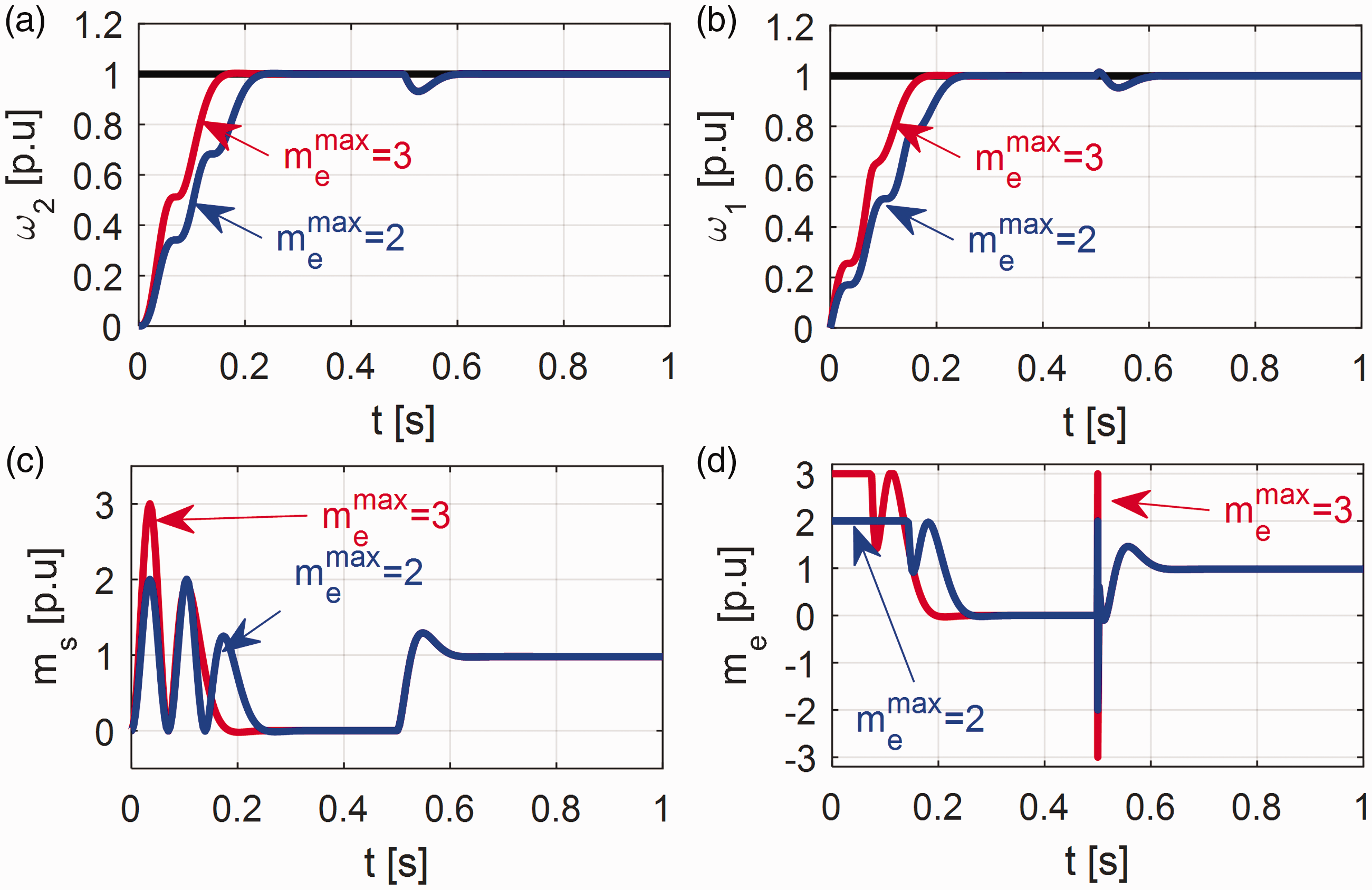
In Figure 6 (a) and Figure 6 (b) the speeds are presented for different values of the limitation of the drive torque. The transients of drive and shaft torques are shown in Figure 6(c) and Figure 6 (d), respectively. Oscillations visible in the transients of the shaft torque cause oscillations in the system speeds during start-up. It is clearly seen that the level of the limitation influences the dynamics of the system. Thus, the smaller the limitation, the bigger setting time achieved.
Then the cascaded-FDC is examined. As presented in the previous section, the system has two major loops: inner shaft torque; and outer load speed loops. As compared to the full-FDC, the feedbacks from the load torque derivatives are not evident in the structure. However, some drawbacks are also expected. First the properties of the inner (shaft torque) control loop are examined. The selected transients of the system states are demonstrated in Figure 7.
Transients of the system variables: shaft torques (a, c) and drive torques (b, d) for the system without (a, b) and with (c, d) limitation of the drive torque.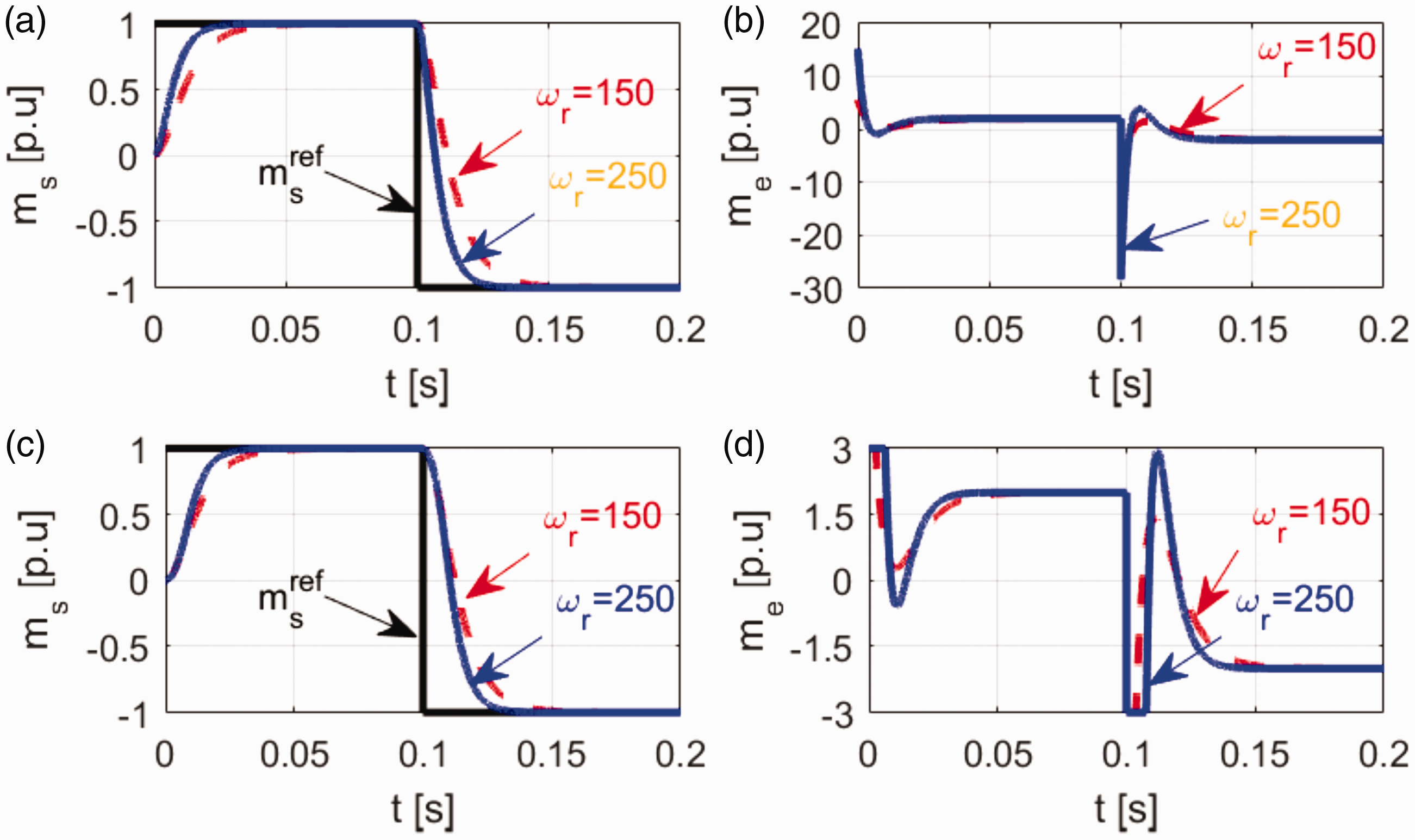
As can be concluded from the transients presented in Figure 7, the dynamics of the shaft torque transients can be set freely in the system without limitation. The settling time and overshoot depend on the design parameters. The inclusion of the drive torque limitation decreases the dynamics of the system, yet the changes are not significant.
Next the whole cascade FDC-based control structure is tested. Systems with and without the drive torque limit are considered. Transients of selected states are shown in Figure 8.
Transients of the system variables: motor (a) and load speeds (b), drive (c), and shaft (d) torques for the system without and with limitation of the drive torque.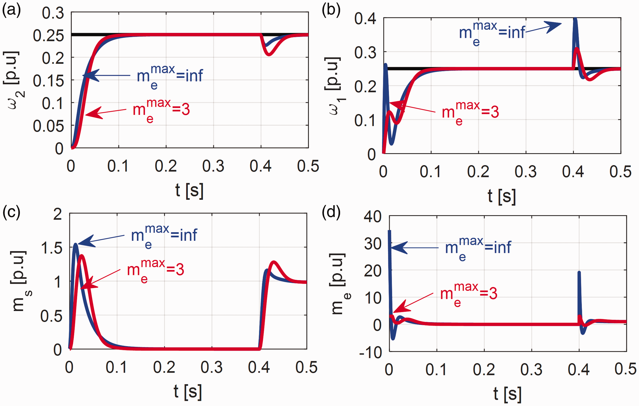
On the basis of Figure 8, the following remarks can be formulated. Firstly, the states of the system without the limitation of the drive torque are forced to be more dynamic than the system with the limitation. This is clearly visible in the motor speed and drive torque transients. The rise of the motor speed is much faster as compared to the other case. This difference disappears in the transients of shaft and load speeds. Secondly, for both examined cases those transients look alike. During the application of the load torque the difference is visible. The system without the limitation rejects disturbance faster, yet it is caused by forcing a large drive torque that is unrealistic in real-time application.
In the last part of the simulation study the comparison of transients saved from both structures is shown (Figure 9). The following conditions are put to the test. The limit of the drive torque is set to 2. Additionally, in the cascade control structure the shaft torque limit is set to 1.5. As can be concluded from Figure 9, both systems are working correctly. The rising time is affected mainly by the set limit of the drive torque. In the full-FDC control structure visible oscillations exist in all states (speeds and torques), which results in additional torsional stresses in the shaft. Due to the fact that the shaft torque is directly controlled in the cascade control structure, there are no oscillations in this system. The speed rises smoothly during the start-up. The reaction to the changes of the load torque in both systems is similar.
Transients of the motor (a), load (b) speeds, drive (c), and shaft (d) torques for the full- and cascade- forced dynamic control (FDC)-based structure.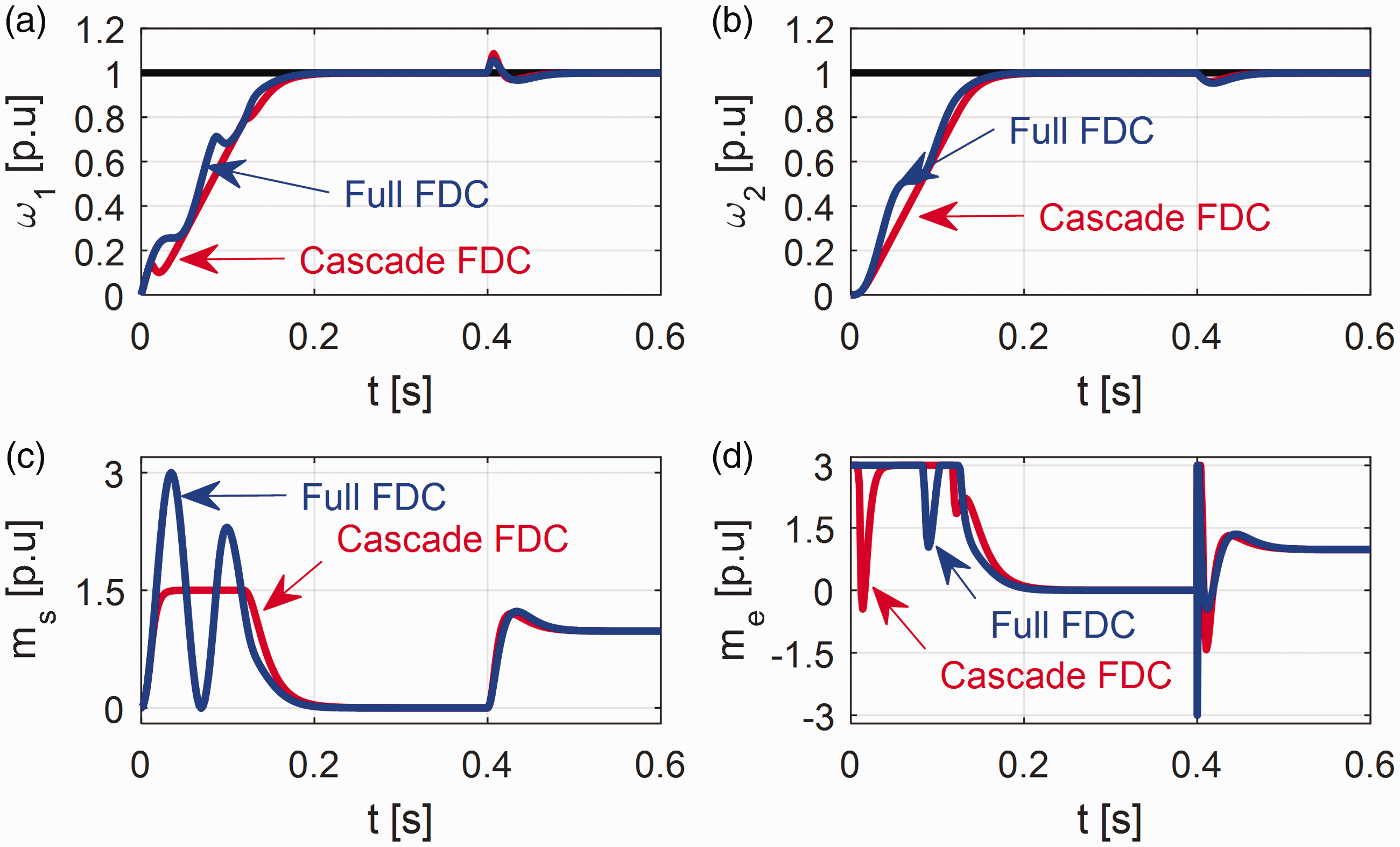
5. Experimental study
The theoretical considerations and simulation tests have been confirmed on a laboratory set-up. The experimental stand consists of two direct current (DC) motors connected by a shaft of l = 600 mm length. The first motor is a driving unit supplied by a DC chopper. The second motor is used to generate load. Both motors are equipped with incremental encoders. The DSpace DS1103 control card is used to implement control algorithms. The chopper was controlled by a pulse width modulator, carrier frequency 13 kHz, and cooperated with a PI-type current controller. Drive motor speed was measured by a Kubler incremental encoder with a resolution of 36,000 pulses per revolution. A pictorial view of the experimental setup is presented in Figure 10.
Pictorial view of the experimental setup.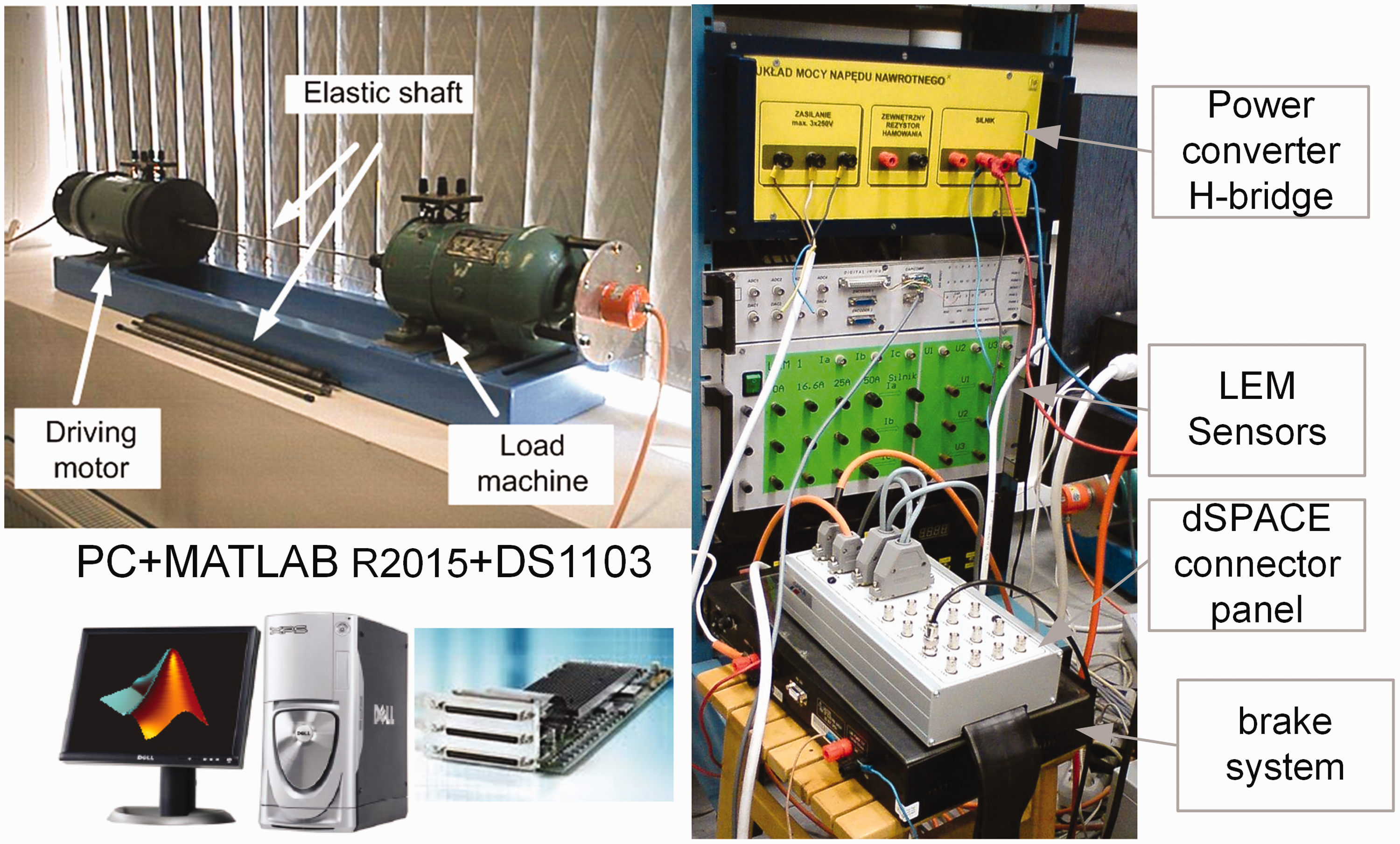
The armature current is measured with a LEM sensor. On the basis of motor speed and armature current the rest of the variables needed for both control structures are estimated using the Kalman filter technique (Szabat and Orlowska-Kowalska, 2012).
First, performances of both control structures working for the small value of the reference signal are tested. The value 0.25 is selected in order to avoid the limitation of the drive torque. The transients of selected state variables of both systems are shown in Figure 11 (a), Figure 11 (b), Figure 11 (e), and Figure 11 (f).
Transients of the system variables: drive and shaft torques (a, c, e, g), motor and load speeds (b, d, f, h) for small (a, b, e, f), and big value of the reference signal for full- (a, b, c, d) and cascaded (e f, g, h) forced dynamic control structure–experimental study.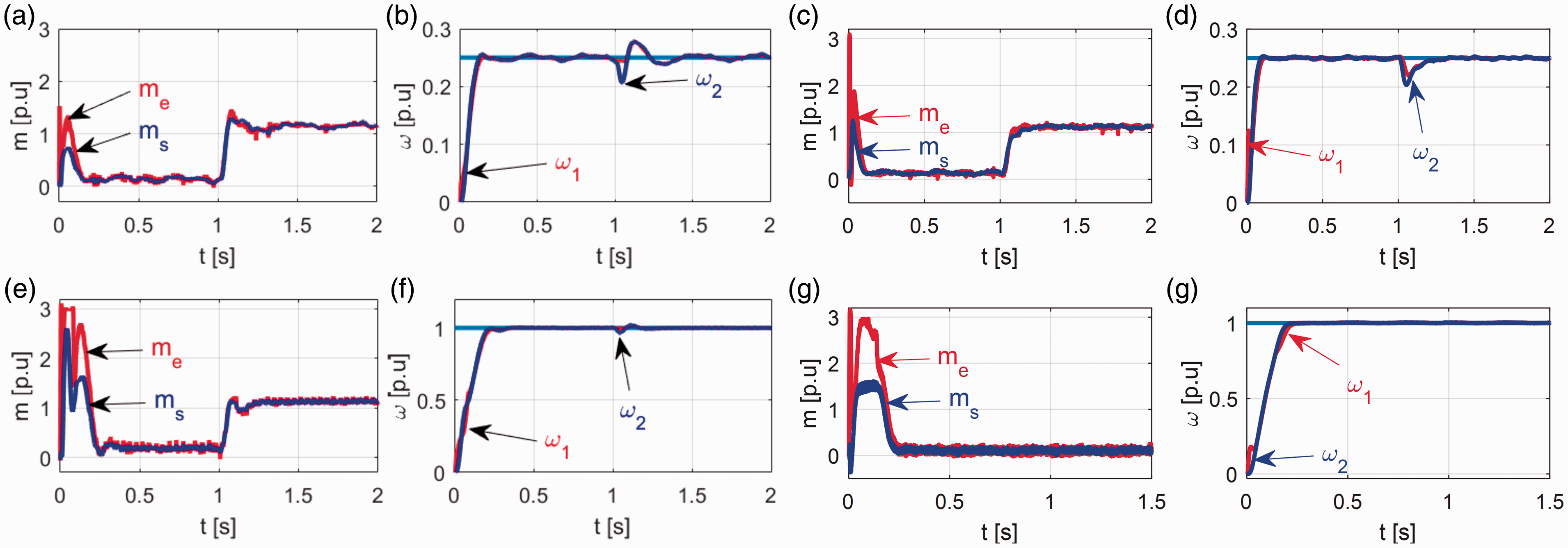
From the presented transients the following conclusions can be formulated. At the time t = 0 seconds the reference signal changes its value to 0.25. Then at the time t = 1 second the nominal load torque is applied to the system.
Both tested systems are working correctly. However, in the speed transients of the full-FDC structure small oscillations are visible (Figure 11 (a) and Figure 11 (b)). They result from the imperfectness of the estimated derivatives of the load torque needed for this control structure. This problem can be partially reduced by designing more sophisticated estimation algorithms–but the need to estimate so many states is a weak point. The application of the load torque causes speed drop and small oscillations. The transients of the cascade control structure are shown in Figure 11 (e) and Figure 11 (f).
Similarly, the rising time of the speed depends on the design parameters of the drive. Compared to the previous case the speeds of the system are stabilized in a more accurate way. Also, the torques have smoother shapes. The reaction of the system to the changes of the load torque is also smoother. There are no additional oscillations in the speed, which results in a shorter settling time.
Then the system working for the nominal value of the reference signal is investigated. The main point of the test is to observe the effect of the drive torque limitation. The transients of the system from both control structures are shown in Figure 11 (c), Figure 11 (d), Figure 11 (g), and Figure 11 (h). In both control structures the limit of drive torque is set to 3. The shaft torque limit is set to 1.5 for the cascade control structure.
The motor and load speeds and drive and the shaft torques from the full FDC base control structure are presented in Figure 11 (c) and Figure 11 (d). As can be clearly seen, during the period of limitation the shaft torques oscillate (Figure 11 (d)). This causes the oscillations of both speeds, which can be seen in Figure 11 (c). The transients from the cascade control structure are demonstrated in Figure 11 (g) and Figure 11 (h). It can be clearly observed that the shaft torque transient has no oscillations (Figure 11 (g)). This results in smooth transients of both speeds (Figure 11 (h)). Due to this fact the settling time of the cascade system is a bit shorter than a full FDC control structure.
6. Conclusions
In this paper the design methodology of two FDC-based control structures for a drive system with an elastic joint is presented. Firstly, the control law for full-FDC control algorithm is developed. Then the cascade FDC base approach is considered. The properties of both control structures are analyzed under a variety of simulation and experimental tests. On the basis of the theoretical considerations and tests the following remarks can be formulated:
The full FDC control structure allows to locate the poles of the closed-loop control structure in every desired position. This means that the type of the load speed response depends on the designer of the system and can vary in a wide range. The factors which limit this feature are the limitation on the control signal and states of the system. It should be mentioned that in real-time application the quality of the estimated states plays an important role. Theoretically, the effect of the load torque is rejected from the load speed. However, in real-time application this feature is limited by limitation of the control signal. This means that only slow changeable torque (e.g., in pressing machines) can be rejected effectively. The full FDC control structure requires the additional feedbacks from the states and the load torque and its derivatives. So, some advanced estimator is necessary to implement in practice. This complicates the realization of this algorithm. There is no direct possibility to limit the value of the shaft torque in the full FDC structure, which can be crucial in some applications. The cascade FDC control structure is simpler to design and analyze due to the fact that the design procedure is divided into two steps. Due to the cascade concept the assumption of the bigger dynamics of the inner loop in comparison to the outer loop must be held during the design process. Contrary to the cascade concept, the disturbance affecting the outer loop is taking into account the design process of the inner loop. This improves the quality of control. The cascade control structure allows to limit the shaft torque in a natural way. The ratio of the limitation of the shaft to the drive torque influences the properties of the control significantly. Its proper value allows to avoid the oscillations of all system state variables. In the system with limitation of drive torque and shaft torque the cascade control structure ensures better properties than the full-FDC control. The oscillations of the state during limitation are eliminated. The speed drops due to the step load torque are similar in both structures.
Footnotes
Declaration of Conflicting Interests
The author(s) declared no potential conflicts of interest with respect to the research, authorship, and/or publication of this article.
Funding
The author(s) received no financial support for the research, authorship, and/or publication of this article.