
Abstract
Damping plays a critical role in power generation by piezoelectric energy harvesting, and yet there is a lack of sensitivity studies on different sources of damping. In this paper, two damping sources in unimorph piezoelectric energy harvesters, namely support loss and damage damping mechanisms, are experimentally investigated. Variations of the power generation are evaluated with respect to the sources of damping. Accordingly, the power generation model is developed according to the experimental results in this work and using a single degree of freedom analytical model. This study focuses on the debonding effect, as an internal damping source, and support loss, as a critical source of external energy dissipation. The results show that the debonding reduces the output power dramatically at resonance and, particularly, at anti-resonance frequencies. Moreover, investigation of the support loss shows that the material of clamp as well as installation torque have an impact on the support loss and, consequently, affect the output power.
1. Introduction
With the recent developments in electronics, for example, the decrease in power consumption (Khaligh et al., 2010), low power energy harvesting from thermal and kinetic sources of energy is being widely considered as an essential tool to introduce self-powered devices for elaborating system abilities in terms of life time and accessibility of remote systems (Ahmed et al., 2017). Furthermore, energy harvesting systems can be manufactured using additive manufacturing techniques (Mortazavinatanzi et al., 2018) for flexible ink-based nonflat surfaces (Qing et al., 2018; PiezeTech Arkema Group, n.d.). Among the energy harvesting mechanisms, piezoelectric energy harvesters (PEHs) have drawn much attention due to structure simplicity and ease of integration into the host structure (Khazaee et al., 2019). Piezoelectric materials can be grouped into three types: ceramic; polymer; and composite (Ahmed et al., 2017). Macro-fiber composite (MFC) with ceramic fibers is a composite material with excellent electromechanical properties of ceramics as well as polymeric flexibility (Khazaee et al., 2019), that makes it an ideal material for long-endurance kinetic energy harvesting.
Unimorph geometry is one of the most widely used configuration for PEHs (Li et al., 2014), in which one piezoelectric layer is bonded into a nonpiezoelectric substrate shim with clamped-free boundary condition. A number of researchers used MFC materials for PEH in unimorph configuration (Sodano et al., 2006; Erturk et al., 2008; Shan et al., 2015; Khazaee et al., 2019). Shan et al. (2015) used a bonded beam from MFC and polyvinyl chloride layers in the clamp-free boundary condition. The beam was subjected to water vertexes induced from an upstream cylinder for PEH and obtained a maximum output power of 1.32 µW. Moreover, by an experimental study. Sodano et al. (2006) compared the maximum instantaneous power of three types of materials in unimorph geometry, including the MFC material, over 12 bending modes and obtained 11.714 µW at third bending mode. Obtaining maximum power from vibration sources is the main research subject within PEHs. Reddy et al. (2016) introduced a cavity inside the substrate beam in order to enhance harvested power from PEHs. In the context of power estimation, it is a well-known fact that damping has a critical role on the output power by PEHs (Roundy et al., 2003). Four factors contribute into energy dissipation of unimorph PEHs, namely energy dissipation from air resistance force, squeeze force, internal energy dissipation, and support loss (Hosaka et al., 1995).
Internal energy dissipation in composite structures is a parameter influenced by five factors, namely matrix or fiber viscoelasticity, interphase, damage, viscoplastic, and thermoelastic (Chandra et al., 1999; Bhattacharjee and Nanda, 2018). In almost all numerical and experimental studies on PEHs, a perfect bonding has been assumed, while adhesion loss or debonding due to the aging or improper manufacturing process is a major concern about adhesive joints (Pazand and Nobari, 2017). Saravanos and Hopkins (1996) showed that delamination cracks between layers of a composite beam increases modal damping of the beam. Although debonding can have a substantial effect on damping (Khazaee et al., 2018) and consequently will change the PEH power dramatically, there is currently no investigation on the effect of this damage on the output power.
Support loss, also called clamping loss, is the energy dissipated from a vibrating structure through its support. As the structure undergoes flexural vibration, it excites its support both by shear and moment forces causing elastic wave propagating into the support, which consequently leads to energy absorption by the support (Hao et al., 2003). Chen et al. (2017) looked at the support loss in micro-electromechanical systems and introduced it as the inverse of quality factor, which can be obtained through elastic wave propagation through the support. Although all the cantilever clamps are created by screw joints, the studies by Hao et al. (2003) and Chen et al. (2017) did not consider the effect of joint characteristics on the support loss. If the joints are used to provide clamps, then friction regions due to the bolted joints may cause slipping, which is a source of damping (Goyder, 2018). An important source of energy dissipation in bolted joints is joint tightness. High clamping pressure produces greater penetration forces (Ibrahim and Pettit, 2005). Since unimorph geometry is built by clamping the piezoelectric harvester with the screw, any source of energy dissipation in the clamps, including joint tightness, should be considered for investigation of power generation by a piezoelectric layer.
Within the energy harvesting research area, which is highly dependent on the different aspects of vibrational characteristics of the device, there is a lack of studies investigating the dependency of the power to vibrational features within the system such as damage and support damping mechanisms. Thus, in this paper a series of experimental studies are carried out to investigate the effect of debonding, as one of the regular defects in adhesive layers, and support loss on output power of a composite beam with MFC piezoelectric layer. In addition, using a single degree of freedom method, change of the power with respect to debonding and support loss is modeled as the damping variation within the system.
2. A modeling technique for unimorph harvester
There are various techniques for modeling of PEHs ranging from simple one degree of freedom (1D) to two-dimensional multi degree of freedom methods. While 1D methods require fewer parameters to model the system, other methods require more parameters to be defined and are computationally time consuming. Moreover, as proposed by Erturk and Inman (2008), a 1D method that considers electro-mechanical coupling can be a suitable method for assessment behavior of piezoelectric harvesters. 1D methods were previously used for studying PEHs (Roundy et al., 2003; DuToit et al., 2005; DuToit and Wardle, 2007). In this study, the experimental data and analytical model are correlated to obtain the damping coefficient in many case studies in order to keep the model as simple as possible but still accurate. Hence, a 1D model with electro-mechanical coupling is created in a suitable form for the investigation by elaborating the damping coefficient in this model. In the result section, the accuracy of the model is presented to predict the experimental data. Figure 1 presents the schematic of the model, which comprises a piezoelectric mass with internal resistance of R
p
, and a proof mass simply connected to a load resistor, R
l
. This model is valid for the case in which there is no substrate shim. In order to comprise the effect of the substrate, a coefficient, Single degree of freedom electromechanical model (DuToit et al., 2005).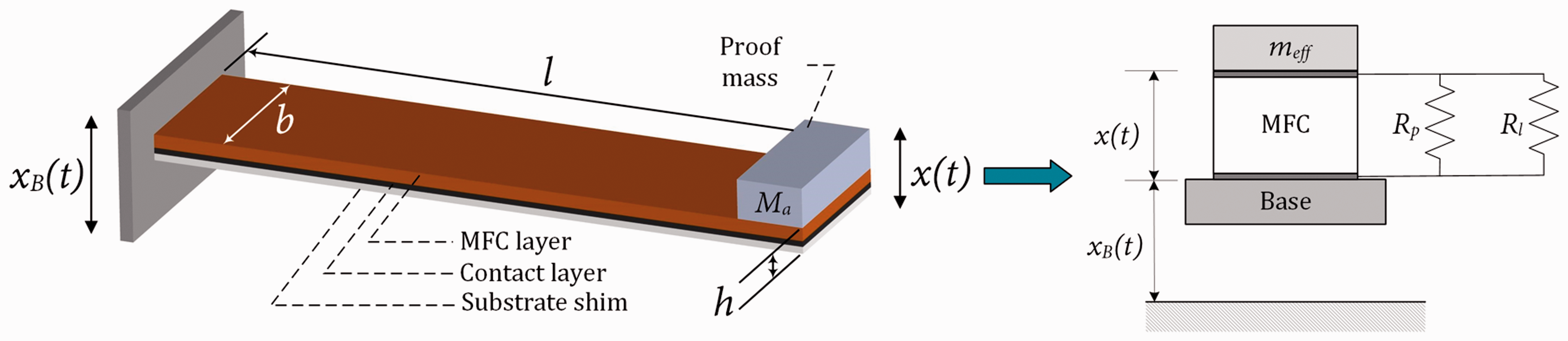


If the base excitation is assumed to be harmonic,
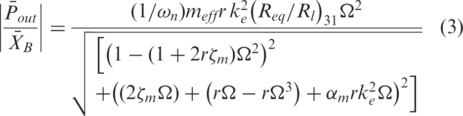
The presented model is a simple 1D model. However, because the output power obtained by this method is expressed in terms of coefficients obtained experimentally, see equation (3), the model presents accurate data compared to the experimental data, as shown in DuToit and Wardle (2007). For instance,
The energy dissipation consists of internal energy dissipation, fluid-structural viscous damping and support loss due to the cantilever boundary condition. For the case of the debonded sample, a damaged damping term is considered. The sources of energy dissipation are shown in Figure 2. Thus, ζm can be expressed by equation (4)
Different sources of energy dissipation considered in this study.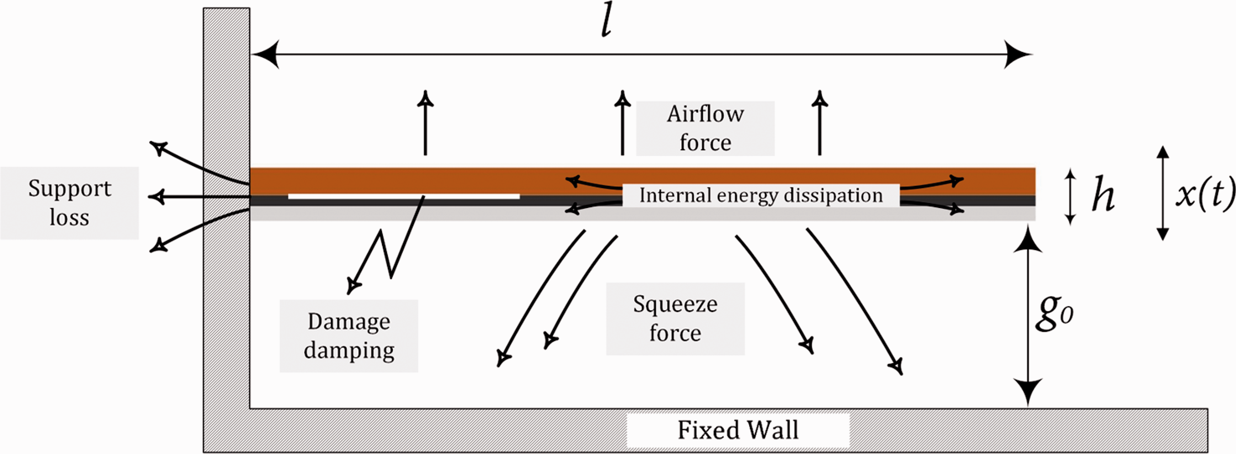

The fluid-structural damping,
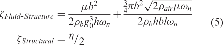
Due to the presence of damping in the equation for output power, equation (3), damping will have a significant effect on the output power in a unimorph energy harvester. This work aims to investigate the effect of changing the damping coefficient, ζ m , through debonding and the support tightness, on the output power while four damping mechanisms are considered (see equation (4)). In Section 4, the support loss damping is evaluated from the defect-free state, which can be used for the debonded state to evaluate the actual damage damping.
3. Experimental procedure
The effects of the debonding and support loss on the output power were investigated through experiments. The experiments were carried out with piezoelectric samples in unimorph geometry. The piezoelectric samples were clamped with a clamp box on one end. Then, they were excited with a magnetic vibration shaker by sinusoidal input signal, where their response in terms of output voltage and current were recorded. Figure 3 shows the configuration of the PEHs throughout the study.
Piezoelectric energy harvester configuration.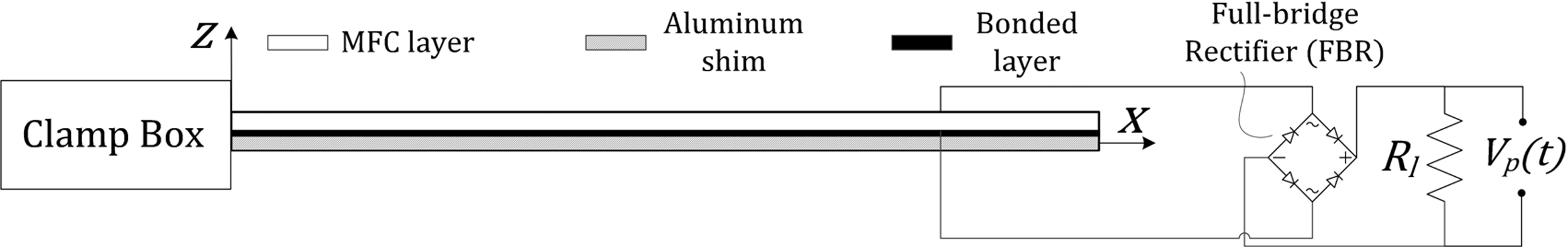
The piezoelectric layer is an MFC with elastic modulus of 30.336 GPa and 15.857 GPa in x- and y-directions, respectively, and Poisson's ratios of 0.31 in xy and 0.16 in yx and shear modulus of 5.515 GPa. Thickness of the MFC is 0.30 mm while the thickness of the lead zirconate titanate fibers are 190 µm with a density of active area of 5.44 g/cm3. The electromechanical properties of the piezoelectric layer are d33 = 460 pC/N, and d31 = −210 pC/N. The center shim is made of aluminum with thickness of 0.12 mm, elastic modulus of 68.9 GPa, and density of 2.7 g/cm3. The piezoelectric layer is bonded to the center shim with epoxy rapid 332 adhesive with density of 1.16 g/cm3. For investigation of the debonding effects in Section 4, thickness of the bond layer in perfect and poorly cured bond conditions are 400 and 189 μm, respectively. In Section 5, where effect of the support loss damping is investigated, the bond layer thickness is equal to 245 µm.
The aforementioned unimorph energy harvester is excited with a VSD 201 Shaker while its input voltage and electrical power are measured. Signal generation and data recording were carried out with National Instrument modules. For signal generation, NI 9263 module, a 4-channel ± 10 V 16-Bit Analog Voltage Output, which is adjusted by LabVIEW™ 2013 is connected to a Kepco AC power generation and the output from Kepco power supply is wired to the shaker. A NI 9215 module with 4-channel ± 10 V 16-Bit Analog Voltage Input is used for recording the voltage output of the piezoelectric harvester. A National Instrument Compact data acquisition system (cDAQ) type 9172 is used as the medium between the modules and experimental components, for example, the shaker and piezoelectric samples. Figure 4 shows the experimental setup.
Setup for measuring voltage output.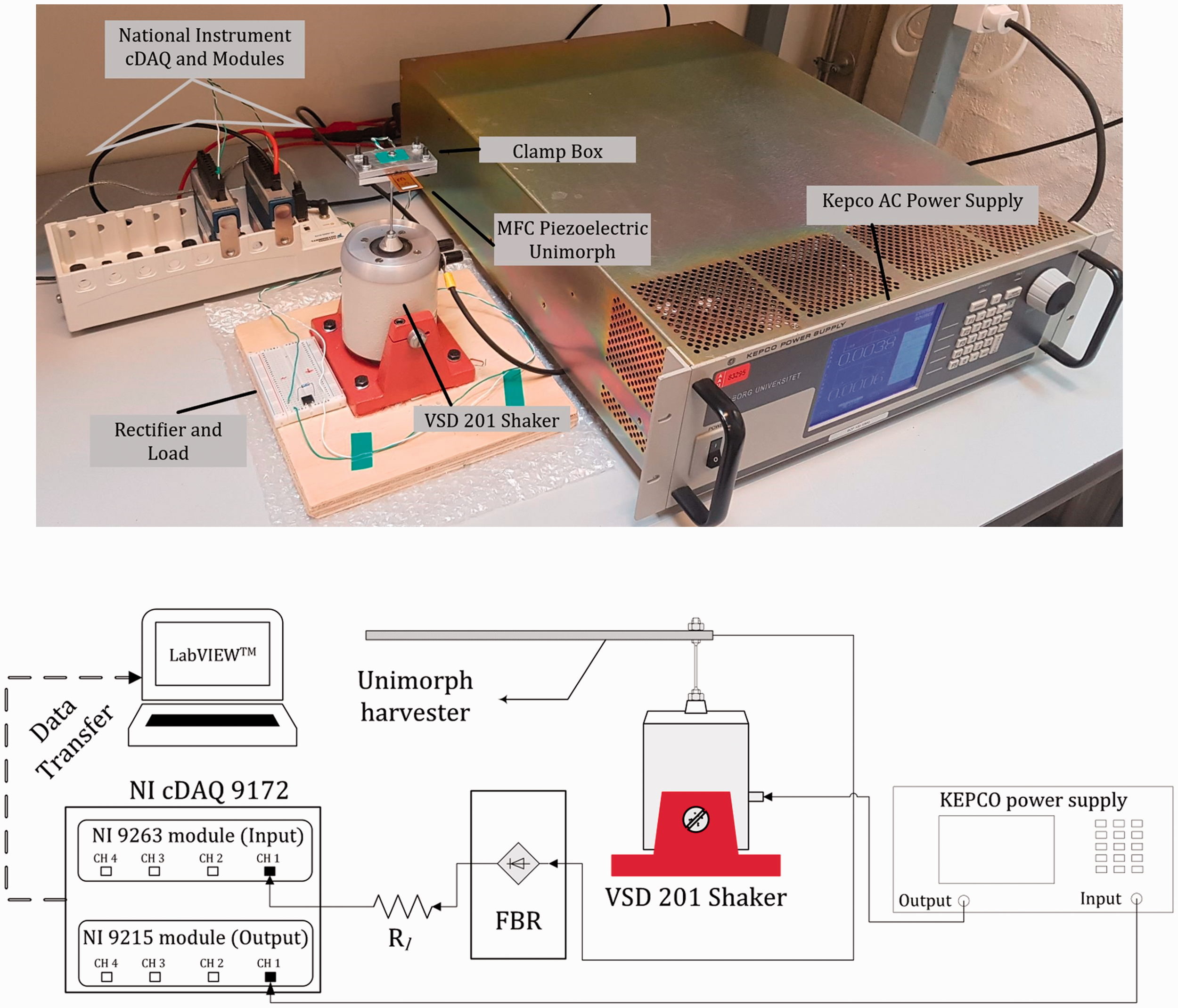
4. Debonding effects
During the model derivation for the PEH from vibration, mostly cantilever configuration is considered with the perfect bonding between piezoelectric and metal substrate. In practice, the perfect bonding assumption may be degraded over time during operation or during the manufacturing process in the first stage (Pazand and Nobari, 2017). In particular, as the loading condition is dynamic and the harvester mostly vibrates close to its fundamental natural frequency, it is likely to observe debonding between the substrate and the piezoelectric layer. The debonding might have two influences on the output power. An obvious effect is that it prevents the vibration of a part of the energy harvester, so it will reduce the active area for power generation. Moreover, the debonding may increase the damping ratio of the device, which results in less power generation. This increment in the damping depends on the vibration mode (Khazaee et al., 2018). In this section, an experimental verification of the debonding effect on the output power is presented.
Two samples are tested with the same length and width, each consisting of a 0.3 mm thickness MFC piezoelectric layer. The samples are bonded to an aluminum substrate with 0.12 mm thickness by epoxy rapid 332 adhesive. Figure 5 shows the pristine and debonded samples with capacitance of Cp = 177.07 nF/m for an active length of 85 mm. The piezoelectric harvester is connected to a 31500-Ω resistance load. The unimorph is excited over a frequency range of 5 to 100 Hz with 1 Hz frequency step with the same excitation amplitude. Three replications are used to show the repeatability of tests.
Macro-fiber composite pristine and debonded dimensions and unimorph configuration with clamp box screws.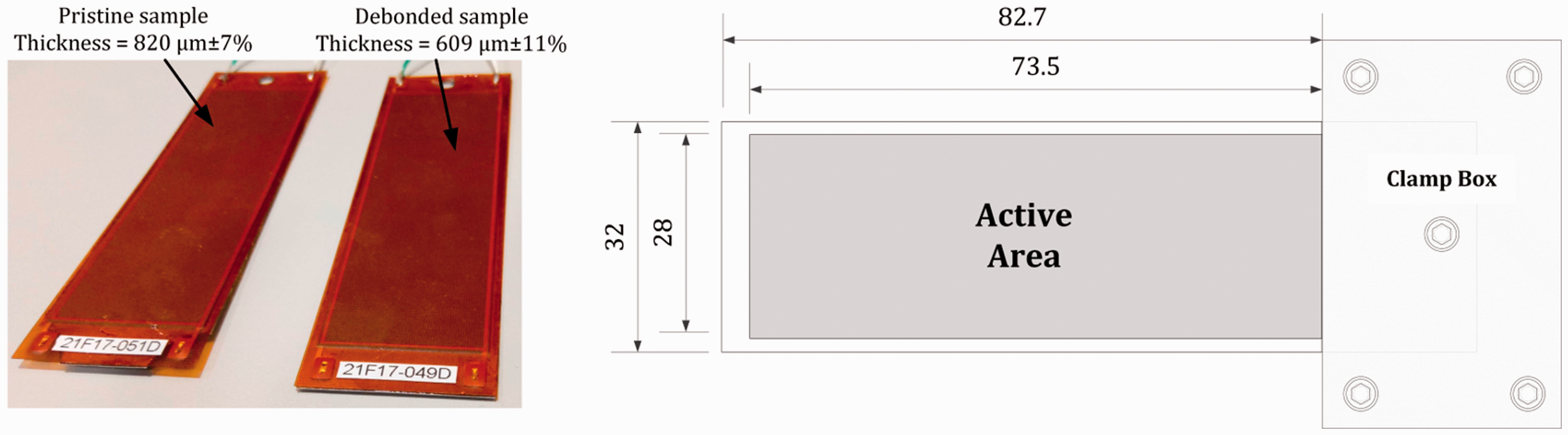
As can be interpreted from Figure 5, thickness of the adhesive layer for one sample was considered 211 µm less than the other sample to make it vulnerable to debonding due to inappropriate debonding thickness. Then, the sample was excited by the shaker on its natural frequency until a debonding area is initiated and developed. It is worth mentioning that after initiation of the debonding, the propagation was quick. The samples were scanned using Acoustic Microscope KSI V8 from the aluminum substrate and from MFC layer down to the other front side to find out the layers within them in which debonding occurred. Figure 6 shows the Acoustic Microscope KSI V8 for scanning the samples from the aluminum side.
Pristine and debonded samples scanned with Acoustic Microscope KSI V8.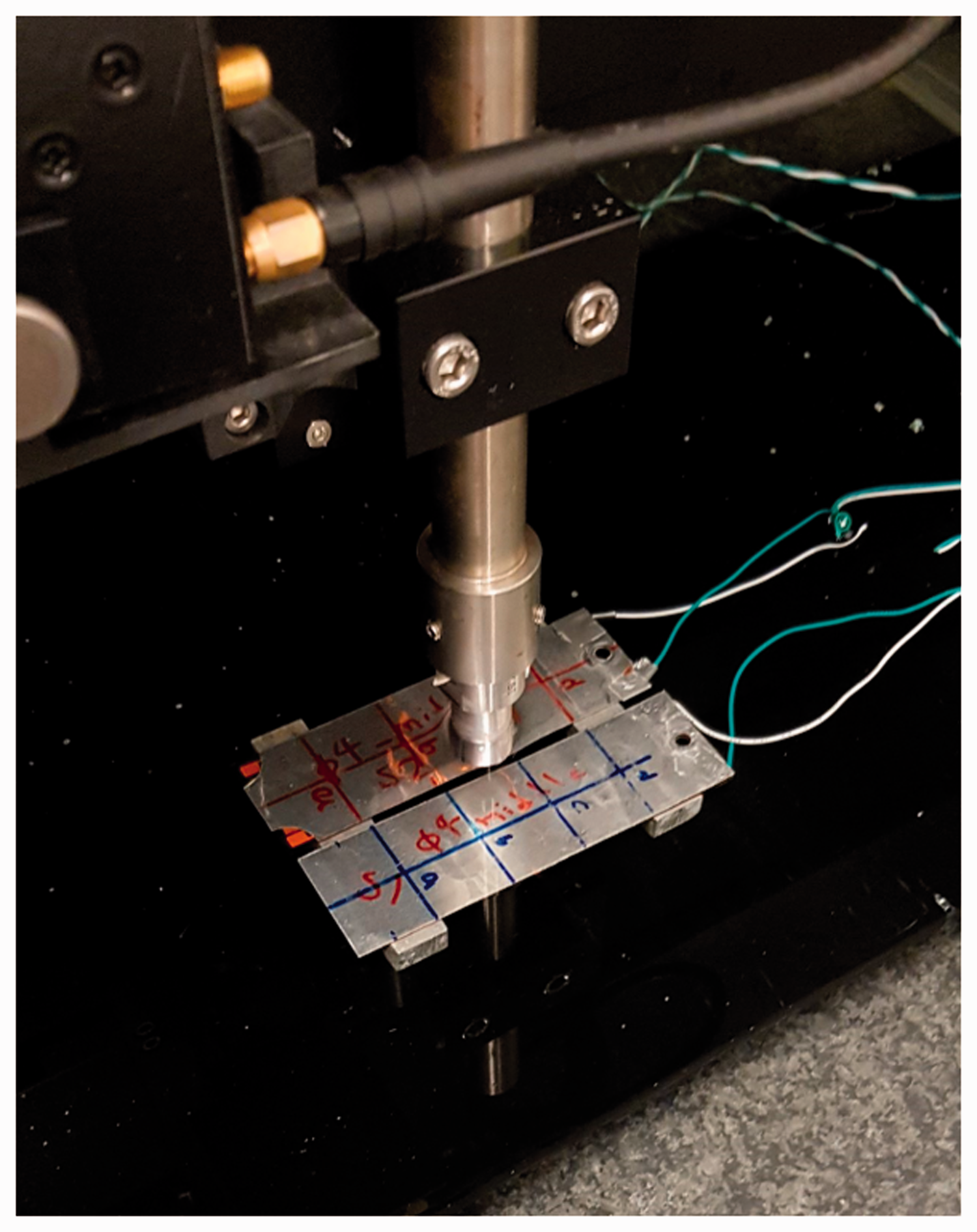
Figure 7 shows the scanned pictures of the samples in depth with ultrasonic waves. Areas with different colors in Figure 7 represent the regions with different densities. In order to recognize debonding regions, similar regions with different colors should be observed at different depth levels. It has been observed that, the debonding was initiated between aluminum shim and adhesive layer, as the color scattering in the surface can be seen from Figure 7 (b)–(c). Since the dark color regions exist at different depths, from Figure 7 (a)–(e), this area is the likelihood-debonding region. This region is marked with a white box in Figure 6. In addition, there are two regions with distinctive colors in Figure 7 (e)–(f) on the pristine sample, which based on thickness measurements is found to be the result of higher density of adhesive in these regions.
Pristine (top sample) and debonded (bottom sample) samples scanned with ultrasonic waves through depth from the aluminum shim side (a)–(f).
Figure 8 shows the frequency spectrum of root mean square (RMS) of the power generation for three replications. Firstly, the results obtained from the duplications are identical, showing that the experiments are repeatable. As it can be seen from the frequency spectrum, there are two peaks for the output power at frequencies of 30 Hz and 49 Hz. The first peak frequency is related to the device fundamental bending natural frequency, while the second peak is a result of the anti-resonance frequency of the device. Anti-resonance frequency is the result of electromechanical coupling. At this frequency, the voltage and current are considerably different from resonance frequency even though the power is similar (DuToit et al., 2005).
Frequency spectrum of power for three replications on macro-fiber composite sample.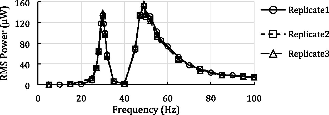
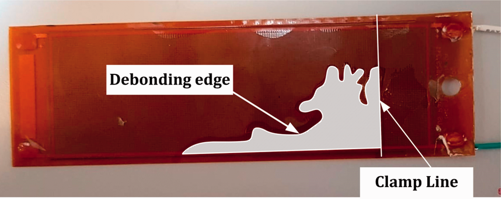
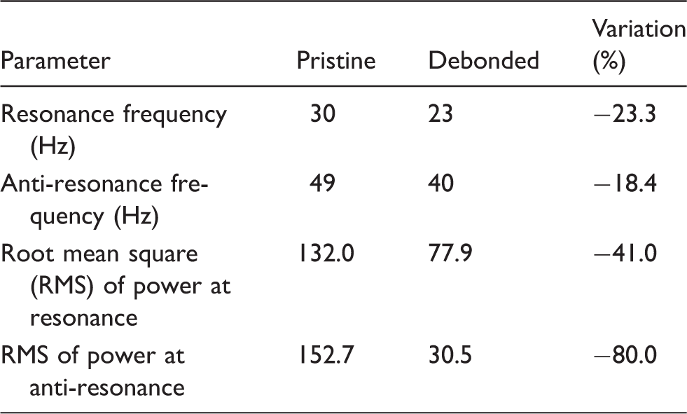
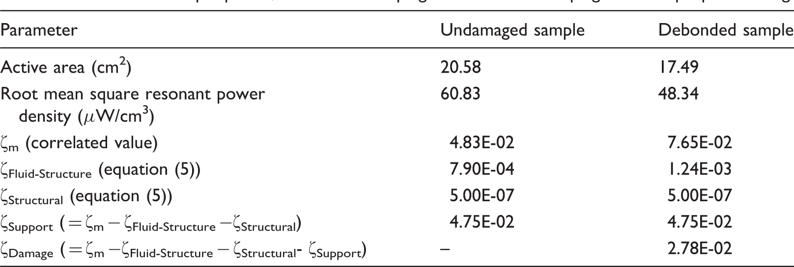
The debonding reduces the active area in the device, which is an important factor in the power generation, and it increases the internal structural. Figure 9 shows the output power from the pristine and debonded samples as a function of frequency. Table 1 shows the variation of peak frequencies and output power between pristine and debonded samples. The debonding reduces the device stiffness and, hence, decreases the resonance and anti-resonance frequencies by 23% and 18%, respectively. Reductions in the peak frequencies are in the same order, showing the stiffness reduction of the beam. Moreover, the presence of the debonding area causes a dramatic reduction in the output power at resonance and anti-resonance frequencies. There are two reasons for reduction of the power generation due to the debonding: reduction of the active area; and increment in the damage damping. To measure the real debonding area, the debonded sample is exploited and the debonding region is marked, as shown in Figure 10. The debonding area is measured to be 15% of the active area. If a uniform generation of power is assigned to the whole area, 15% active area reduction will reduce output power by 15%. Hence, the rest of the power reduction is due to increment of the damage damping. In addition, it can be noted from Figure 9 that degradation of the output power is two times at the anti-resonance compared to at the power reduction at the resonance frequency, proving that the power at anti-resonance is much more sensitive to the debonding effect.
Comparison between power for pristine and debonded samples over different frequencies. Debonded area within adhesive and aluminum layer. Comparison between pristine and debonded samples.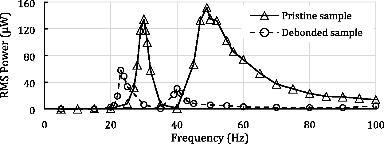
By applying the model presented by equation (3) and by updating the (a) correlated data versus experimental data; and (b) comparison between maximum power at resonance and damping increase due to debonding.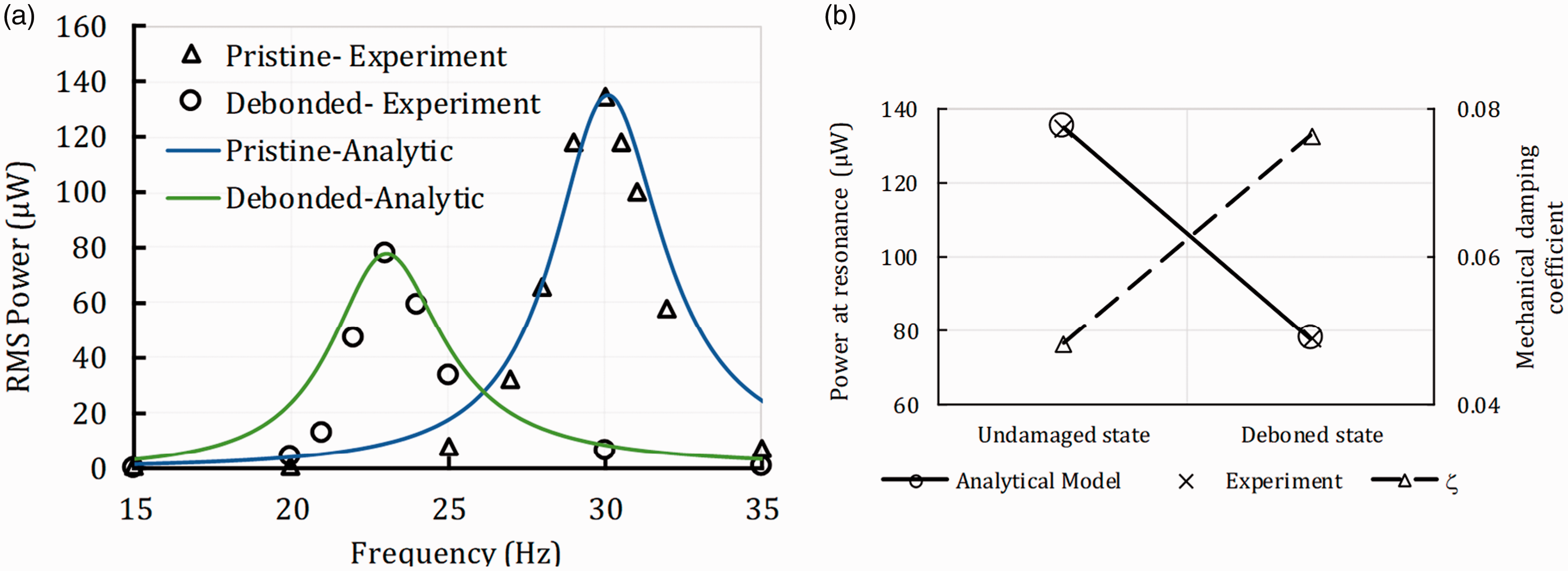
Variation of output power, mechanical damping and structural damping due to improper bonding.
The nature of the damping variation due to delamination in the composite materials has been investigated by Khazaee et al. (2018). The variation in damping depends on the vibrating mode, which causes penetration motion or slip motion between layers near the delamination (Khazaee et al., 2018). Fundamental mode shape of the unimorph harvester is shown in Figure 12. In this mode, if a debonding region is present, layers on top and bottom of the debonding area have a penetration motion in a perpendicular direction which causes an extra energy dissipation mechanism inside the harvesting material.
Mechanical damping increases due to debonding in the first bending mode.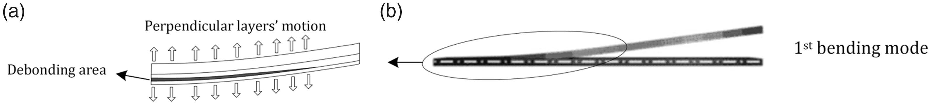
5. Support loss damping
Unimorph or bimorph is among the most applicable configurations of PEHs, where one end is clamped and the other end is free. To create the clamp, often a part of the energy harvester is clamped within a clamp box in which screws are tightened to provide a nonmoving area. Due to this clamp, an extra loss is introduced into the system, called support loss (Hosaka et al., 1995). In this section, output powers from a unimorph PEH under a clamp-free boundary condition with different clamp box configuration are compared to each other in order to study the effect of the clamp characteristics on the output power.
Figure 12 (a) shows the sample for testing the support loss effect on the output power. The thickness of the MFC piezoelectric, adhesive and substrate layers are 300, 245, and 120 µm, respectively. The clamp box consists of two 60 × 30 mm blocks with four screws placed symmetrically in the corners with 6 mm center-to-edge distance and one center hole for the shaker attachment. To observe the effect of the support loss, two types of materials were used for clamp box made by plastic and aluminum, as shown in Figure 13. The weight of clamp box set with screws for aluminum and plastic types are 59.09 g and 25.86 g, respectively. Moreover, the screws of the clamp box were tightened with different torques, and for each set of torques the power was measured over a frequency range close to its natural frequency.
(a) macro-fiber composite (MFC) harvester dimensions and unimorph configuration with clamp box screws; (b) aluminum; and (c) plastic clamp boxes clamping the MFC harvester.
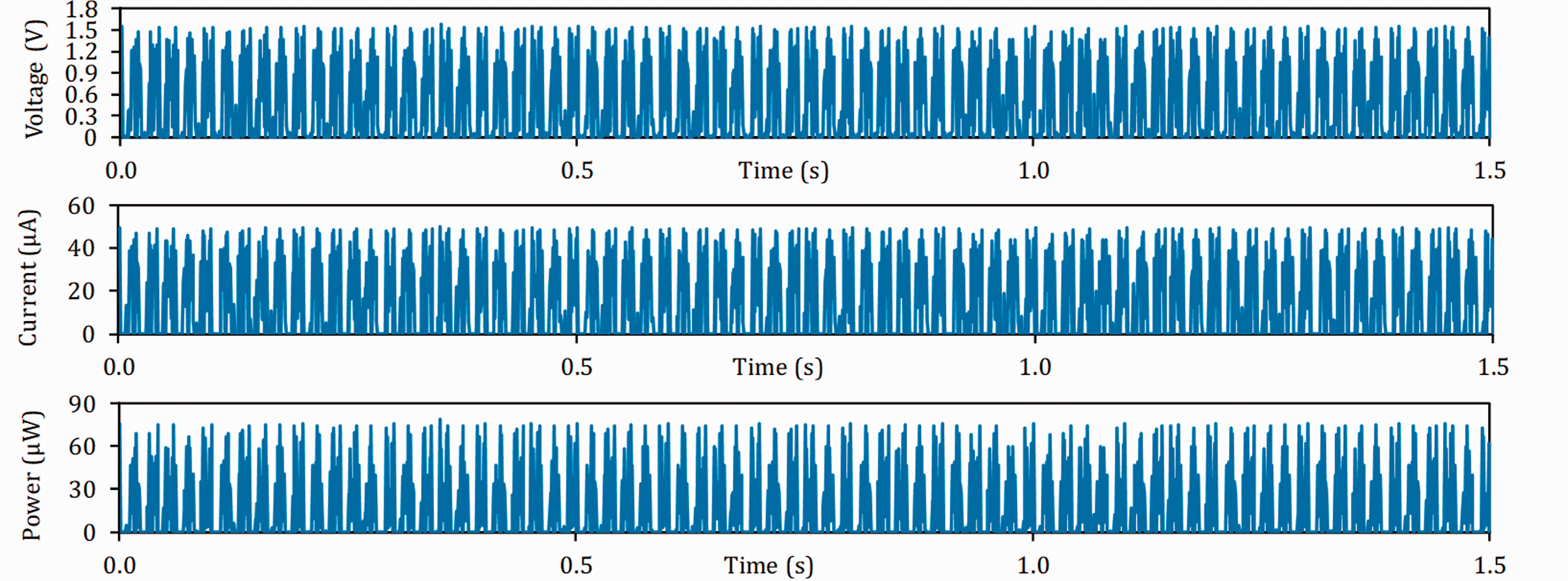
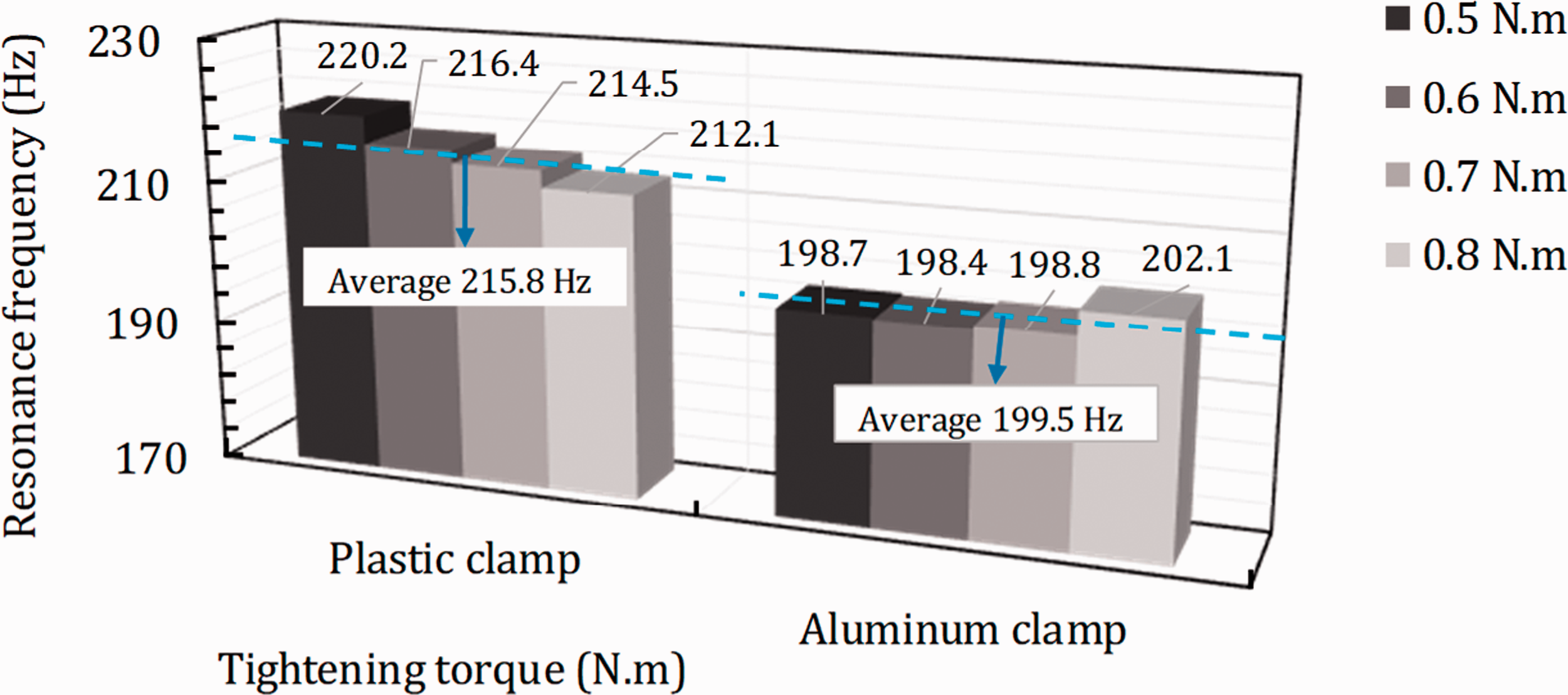
Figure 14 shows the output power density in µW/g over a frequency range including the resonant frequency of the PEH, where g = 9.81 m/s2, from the MFC sample with the aluminum and plastic clamp boxes at different levels of tightening torques. The vertical axis shows the output power normalized to input base acceleration in terms of RMS, when the MFC sample was excited by a harmonic excitation with the maximum force of 17.8 N. For each case of excitation with the specific frequency, the output voltage and current were measured with 31500 Ω resistance load and then the power was calculated by product of the voltage and current. Tightening torque, N.m., was the torque used for fastening the four screws of the clamp box as well as the shaker attachment screw, as shown in Figure 13 (a). A sample of the measured voltage, current, and output power is shown in Figure 15 for a plastic clamp box with tightening torque 0.5 N.m and excitation frequency of 220 Hz. The immediate conclusion to be drawn from Figure 14 is that, the output power spectrums represent different values for different clamp box materials and tightening torques. Therefore, the clamping characteristics play an important role in the energy harvesting by cantilevered piezoelectric beams. The resonant frequency, as displayed in Figure 16, for plastic clamp lies between 212.1 Hz and 220.4 Hz with an average value of 215.8 Hz that is higher than the resonant frequency for the aluminum clamp with an average of 199.5 Hz lying in the interval Power frequency spectrum for sample 3 over changing torque T of aluminum clamp boxes. Voltage, current and power from piezoelectric harvester with plastic clamp with T = 0.5 N.m at 220 Hz excitation. Resonant frequency of piezoelectric harvester for different tightening torques on plastic and aluminum clamps.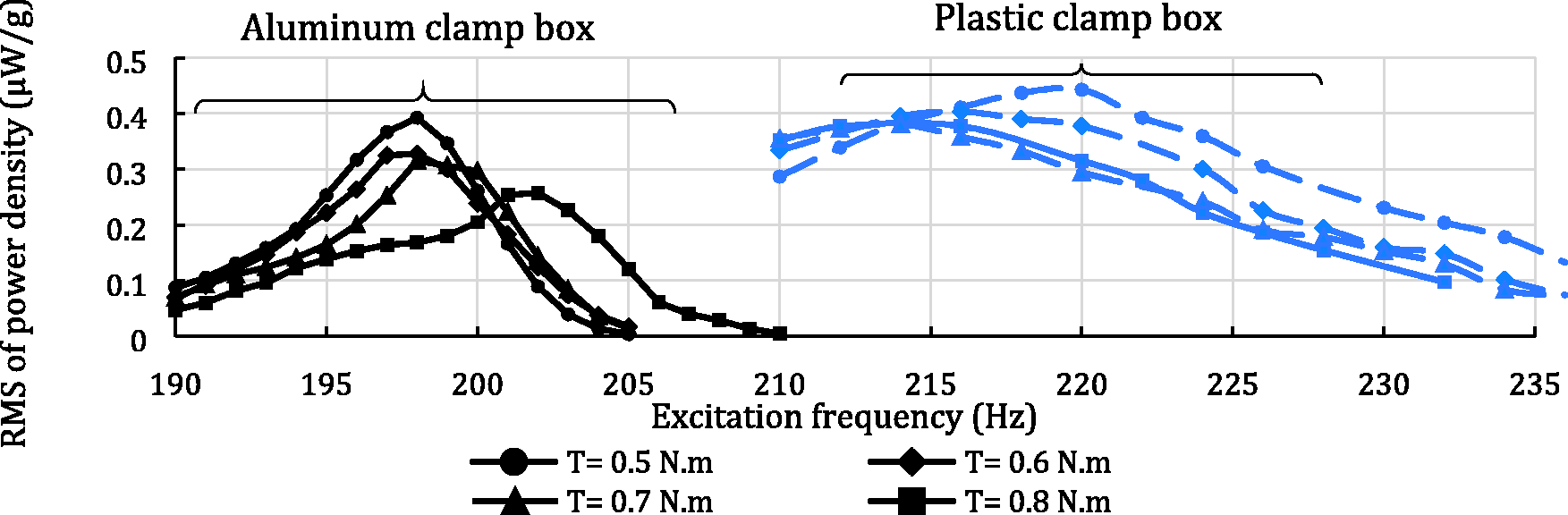
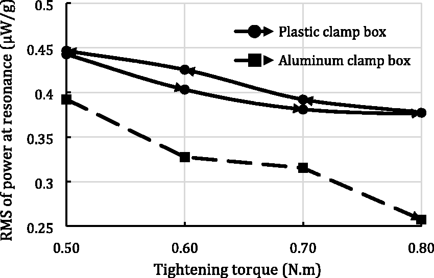
Output current signals over a 1.5 seconds period from the piezoelectric harvester with plastic clamp vibrating at its resonant frequency for different tightening torques are displayed in Figure 17. The RMS of the output currents for tightening torques of 0.5, 0.6, 0.7, and 0.8 N.m are 23.8, 22.2, 21.9, and 21.7 μA, respectively. Therefore, increasing the tightening torque on the cantilever clamp box reduces the output current. Increasing tightening torque from 0.5 to 0.6 N.m reduced the current by 6.7 % while this drop is 1.4% for 0.6 to 0.7 N.m, and 0.9 % for 0.7 to 0.8 N.m tightening torque. Figure 18 shows the power at the resonance at different levels of tightening torque for the aluminum and plastic clamp boxes. Since the plastic clips have a degree of flexibility, to prove that the trend is reciprocal, the tests were performed from the lowest torque, T = 0.5 N.m, to the highest torque, T = 0.8 N.m and vice versa. The results show that the harvester with the aluminum clamp box produced lower power. On the other hand, by increasing the tightening torque of the screws of the clamp box, RMS of the maximum power decreases, for both the aluminum and plastic clamps. Figure 18 implies that the plastic clips, which are more flexible than the aluminum, can provide higher output power and lower support loss compared to that with the aluminum clamp.
Comparison between current measurements at resonant frequency excitation for plastic clamp at tightening torque: (a) 0.5 N.m; (b) 0.6 N.m; and (c) 0.7 N.m and 0.8 N.m. Variation of power versus torque applied on clamp screws for different clamp box.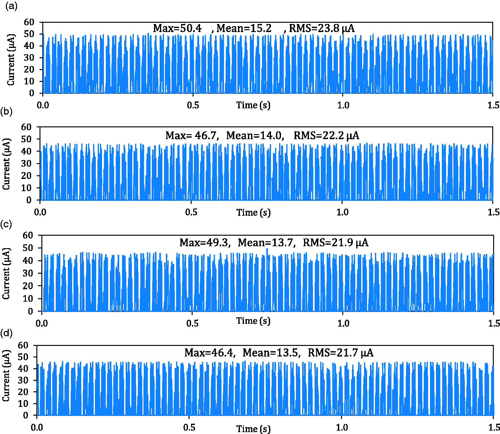
Similar to the previous section, using the developed model for the unimorph harvester, and with the minimization of the error between the maximum resonance powers, the mechanical damping ratios are identified for different clamp boxes at different tightening levels. These identified damping ratios are shown in Figure 19. Overall, the aluminum clamp introduces higher energy dissipation, which in turn causes to reduce the damped natural frequency in Figure 14. Therefore, in comparison with the aluminum clamp box with higher support damping, the lower resonance frequency of the harvester with the plastic clamp box is due to lower support damping. However, with increasing the clamp pressure by higher tightening torque, the support loss increases for both clamp boxes, independent of clamp material.
Variations of identified damping variations versus clamp pressure for aluminum and plastic clamps.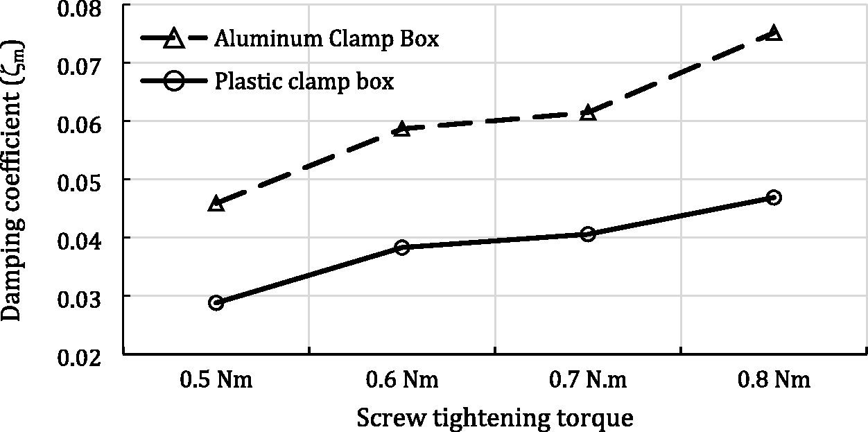
6. Conclusions
This study presented an experimental investigation of the effect of damage and support losses damping mechanisms on the output power of PEHs in unimorph geometry. The results show that by using a simple, but practical, single degree of freedom model, the power variation can be modeled with the mechanical damping variation. The debonding, as an internal source of damping inside the harvester, is investigated in this study. It is concluded that the debonding increases the damping and reduces the output power dramatically. Moreover, the support loss, as an external damping source, has an effect on the output power in such a way that the clamp material as well as clamp pressure will change the output power.
Footnotes
Declaration of Conflicting Interests
The author(s) declared no potential conflicts of interest with respect to the research, authorship, and/or publication of this article.
Funding
The author(s) received no financial support for the research, authorship, and/or publication of this article.