
Abstract
Edgewise vibration in wind turbine blades is one of the important factors that results in reducing the performance of wind turbines. Therefore, control or reduction of the mentioned vibrations can be of great help in increasing the efficiency of wind turbines. In this paper, the shunt damping method is proposed to reduce the edgewise blade vibration of horizontal axis wind turbines. For this purpose, partial differential equations governing dynamics of the system are derived using the Lagrange method. These equations are completely nonlinear and linearization is not performed to avoid possible errors in the analysis. In order to evaluate the effectiveness of the proposed shunt damping method in vibration reduction of the wind turbine blade, obtained results by applying shunt damping method are compared with corresponding results obtained by employing a conventional method known as a tuned mass damper (TMD). For better comparison, by considering proper cost functions, the shunt damper and TMD parameters are optimized using a genetic algorithm. Finally, the effectiveness of optimized shunt damper in vibration reduction of the blade is compared with optimized TMD by presenting simulation results.
1. Introduction
The expansion of new and renewable energies has an ever-increasing impact on the lives of human societies. Wind energy is one of the renewable energies and is increasingly popular due to its low cost and renewable value. Wind turbines are emerging renewable energy extraction solutions (Martynowicz, 2015). Edgewise vibrations in wind turbine blades can be considered as one of the most important factors in reducing the performance of wind turbines (Staino et al., 2012). Therefore, reduction of edgewise vibrations in blades is important to improve the efficiency of the wind turbine. Various approaches, including active, semi-active, and passive methods, have been proposed by researchers in the literature for vibration reduction of the wind turbine blade. Staino et al. (2012) examined the reduction of edgewise vibration of the wind turbine blade using an active method by employing a linear quadratic regulator. Qiao et al. (2012) proposed an active method for vibration suppression of a smart wind turbine blade by employing piezoelectric actuator and sensors. The reduction of the flapwise vibration of the wind turbine blade using a semi-active vibration absorber was investigated by Arrigan et al. (2011). Chen et al. (2015) used a fuzzy method for semi-active control of the edgewise vibration of the wind turbine blade by employing magneto-rheological dampers under extreme wind excitations. Zhang and Nielsen (2014) examined the edgewise vibration suppression of wind turbine blades using a roller and liquid dampers. Agnese and Scarpa (2014) proposed a star-shaped macro-composite for vibration suppression in wind turbine blades. Zhang et al. (2014) investigated the mitigation of edgewise vibrations in wind turbine blades by means of roller dampers. Suppression of wind turbine blade vibrations, taking into account the effect of the nacelle and blade interference, using a tuned mass damper (TMD) was performed by Murtagh et al. (2008).
Piezoelectric materials can be used for the vibration reduction purpose. The concept of shunt piezoelectric damping was first introduced by Hagood and Flotow (1991). They showed that it is possible to add damping to vibrating structures using piezoelectric elements with passive shunt circuits. In this method, the piezoelectric transducer is bonded to a host structure. As the host structure vibrates, the transducer produces electricity. An external shunt circuit dissipates the electrical energy thereby dissipating the mechanical vibration energy, and the vibration of the host structure is suppressed (Yan et al., 2017). The shunt damping method has been investigated by various researchers to reduce vibrations of various structures. For example, the shunt damping method has been employed to reduce vibrations of satellite side panels (Sales et al., 2013), bladed disks (Mokrani et al., 2015), and uniform cantilever beams (Park and Park, 2003).
To the best of the authors’ knowledge, employing the shunt damping method for vibration suppression of wind turbine blades has not been presented in any literature. In the present study, the shunt damping method is proposed to reduce the edgewise vibration of wind turbine blades and compared with one of the conventional methods, i.e. tuned mass damping. In order to achieve better comparison, parameters of the shunt and tuned mass dampers are optimized using a genetic algorithm. In this regard, the governing nonlinear dynamic equations of motion are derived using the Lagrange method. In addition, in this paper, a systematic numerical method to obtain natural frequency and mode shape of the blade is presented. Also, characteristics of a small-scale wind turbine blade including variations of area, mass per unit length, and second moment of area in the longitudinal direction of the blade are determined and presented. Then, optimization of shunt damper and TMD is performed based on the relatively accurate dynamic model of the wind turbine blade. Finally, nonlinear differential equations are solved numerically and the effectiveness of the optimized shunt damper in vibration suppression of the wind turbine blade is investigated in comparison with optimized TMD.
2. Dynamic model of the wind turbine blade and validation
2.1. Deriving dynamic motion equations
Governing dynamic motion equations of the wind turbine blade are obtained using the Lagrange method (Zhang et al., 2014). A schematic of a wind turbine blade with corresponding coordinate systems is shown in Figure 1; (X1, X2, X3) are related to the fixed coordinate system. The edgewise vibration of the blade is described in the moving (x1, x2, x3) coordinate system. The blade has a constant rotational speed of Ω. Therefore, for a wind turbine with three blades, the azimuth angle Schematic of a wind turbine blade with corresponding coordinate systems.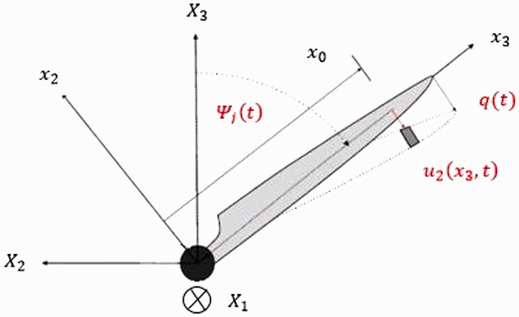

The edgewise displacement of the turbine blade at each point can be calculated as follows:

The kinetic energy of the blade can be calculated as follows:


By substituting the equation (4) into equation (3), the kinetic energy is rewritten as the following equation:

The potential energy of the blade is obtained as (Staino et al., 2012) Components of the gravity loading.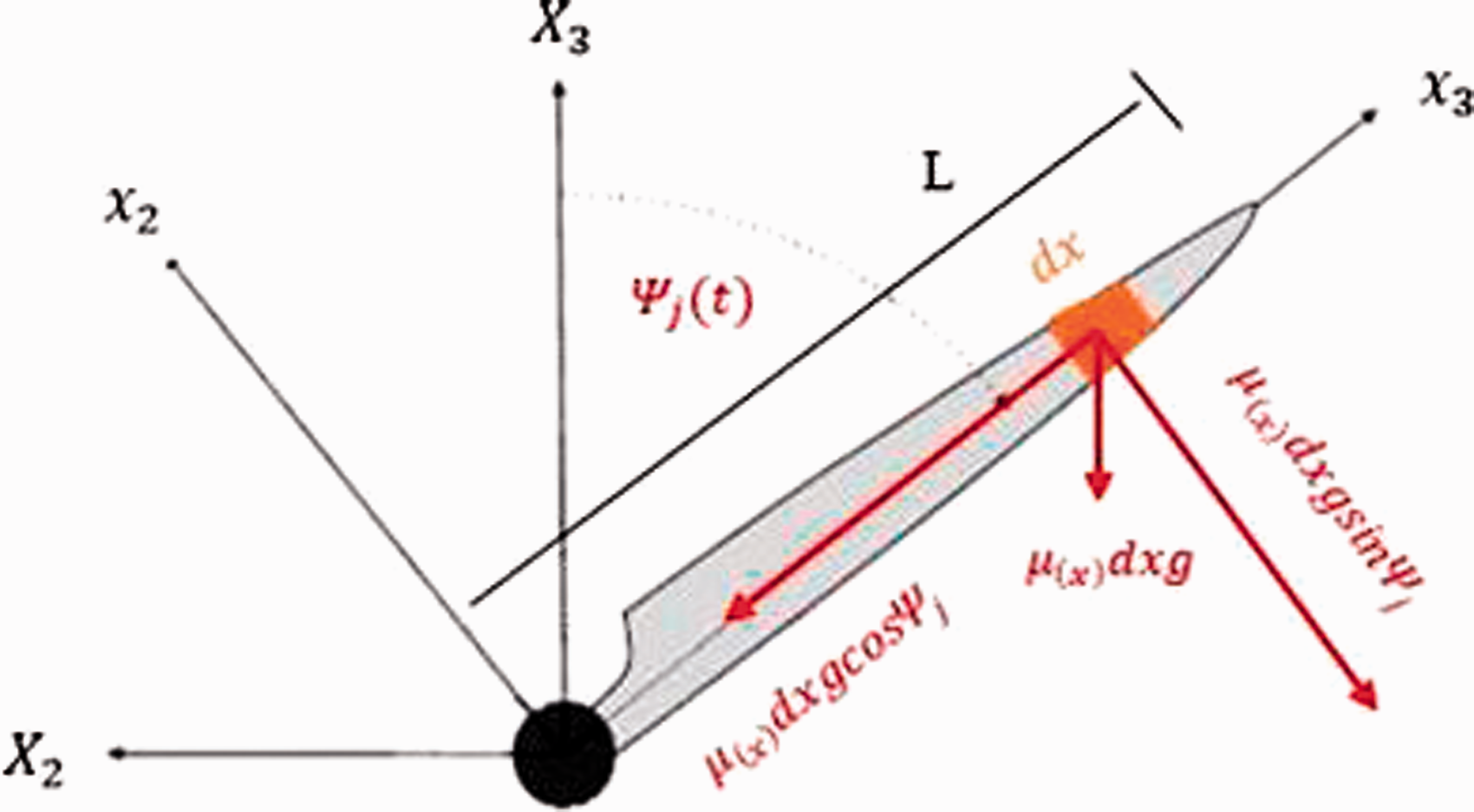

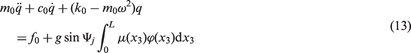
Using the principle of virtual work (Ginsberg, 2008), virtual work of the system is presented as


2.2. Determining wind turbine blade characteristics
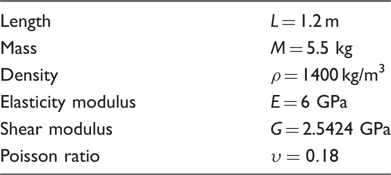
In this study, a small-scale wind turbine blade with an airfoil of S823 is investigated. The mentioned blade has been modeled in computer-aided design (CAD) software and is shown in Figure 3. The general characteristics of the blade are shown in Table 1. Geometric model of the wind turbine blade. General characteristics of the blade (Hamdi et al., 2012).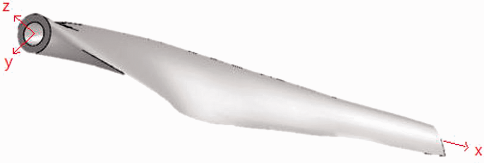
In order to obtain mathematical functions for the variations of the area, mass per unit length, and second moment of area in the longitudinal direction, the blade is intersected in the CAD software in different lengths and characteristics of each section are determined from the software. Then, according to these data, proper curves are fitted to the characteristics that are presented in Figures 4–6. In this way, functions related to the area, mass per unit length, and second moment of area variations in the longitudinal direction of the blade are obtained in the form of Area variations along the blade (data and fitted curve). Mass per unit length variations along the blade (data and fitted curve). Second moment of area variations along the blade (data and fitted curve).

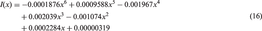
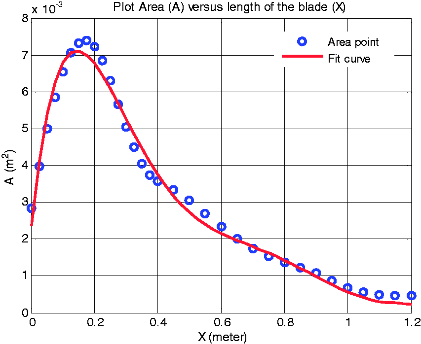
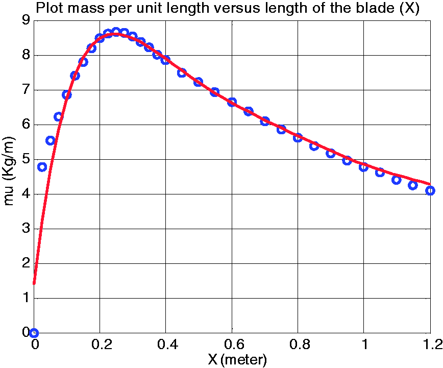
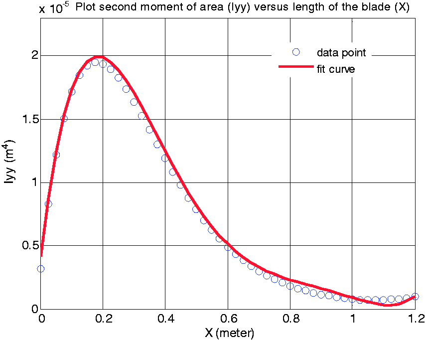
It is noted that the order of polynomials for curve fittings has been selected to be small as much as possible and also leads to proper fitting. In addition, R-squared values related to the performed curve fittings for area, mass per unit length and second moment of area have been obtained 0.9887, 0.9998, and 0.9464, respectively.
2.3. The first natural frequency and mode shape of the blade
Using the Euler–Bernoulli beam theory, the governing equation for the forced lateral vibration of a nonuniform beam (wind turbine blade) is obtained as follows:
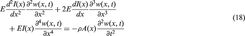
The above partial differential equation can be solved using the separation of variables method. Therefore, the solution of the mentioned equation is assumed as below (Rao and Yap, 2011):
By substituting the equation (19) into equation (18), two ordinary differential equations will be obtained: time and mode shape equations. The mode shape equation can be presented as
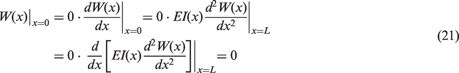
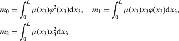
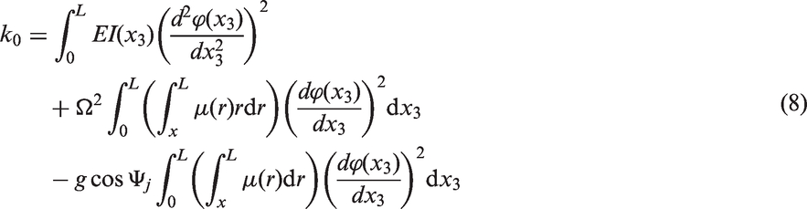
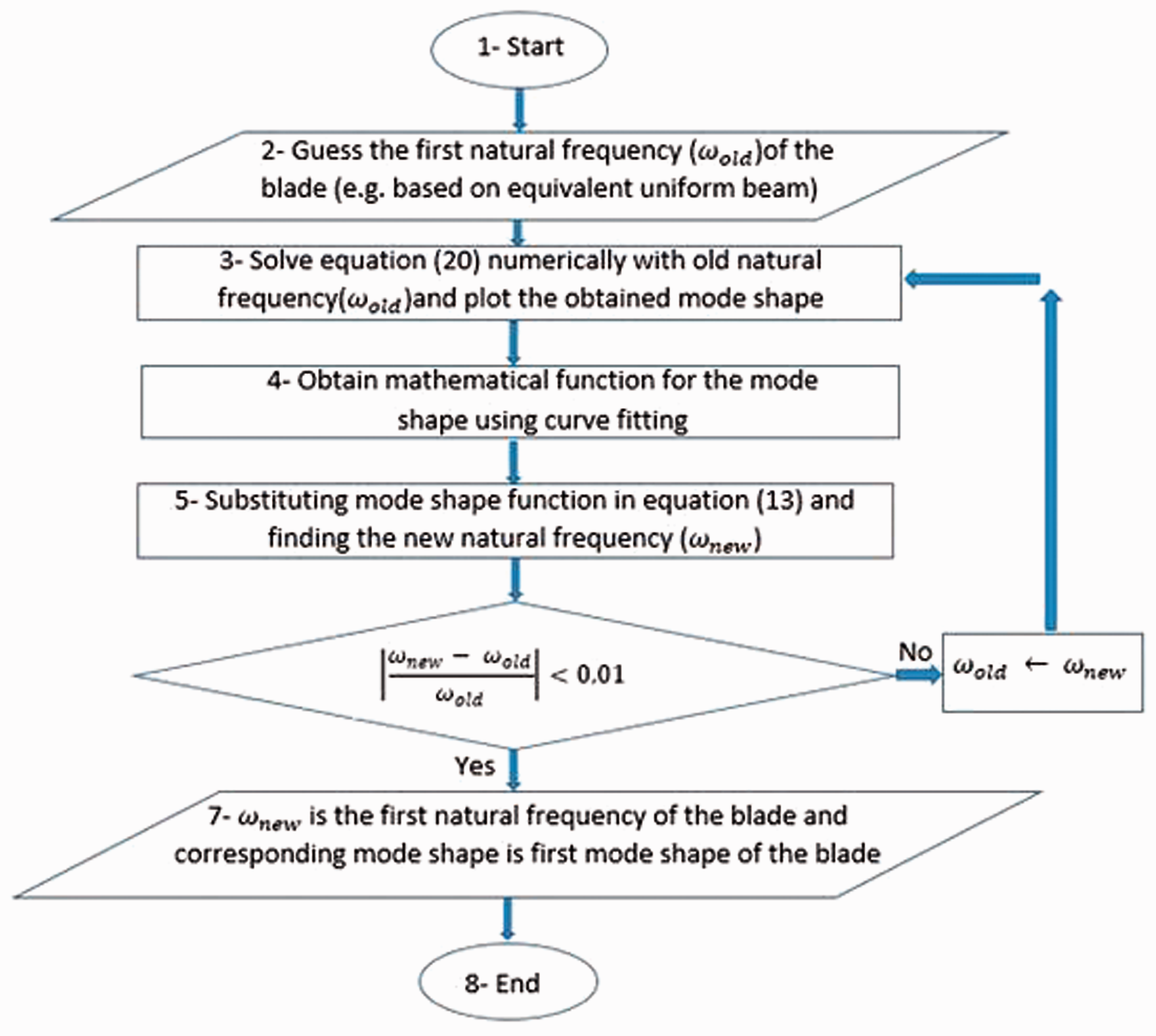
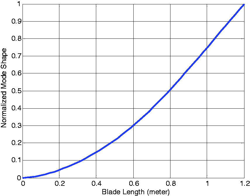
Since in equation (20) the second moment of area and area are variable in the longitudinal direction of the blade, the equation has no analytical solution, and numerical methods need to be used to solve it. In this paper, a systematic method is proposed to obtain the first natural frequency and mode shape of the blade. A summary of this method is presented as a flowchart in Figure 7. Using this method for the considered wind turbine blade in this paper, the first natural frequency of the blade is obtained 69.635 rad/s. In addition, the normalized function for the first mode shape of the blade is obtained as shown in Figure 8, and its corresponding equation is Flowchart for finding the first natural frequency and mode shape of the blade. Normalized function for the first mode shape of the blade.
2.4. Validation of the dynamic model of the blade
In order to validate the dynamic modeling, the first natural frequency of the blade obtained from mathematical modeling is compared with the corresponding result obtained from finite element software. Boundary conditions are considered to be cantilevered (fixed-free). Also, the tetrahedral elements have been used for finite element analysis. The first mode shape of the blade determined from the software is presented in Figure 9. The first natural frequency of the blade is 73.017 rad/s based on the modal analysis in the software. This differs 4.63% from the natural frequency according to the mathematical model (69.635 rad/s). Therefore, the accuracy of the dynamic model is acceptable. The first mode shape of the wind turbine blade simulated in finite element software.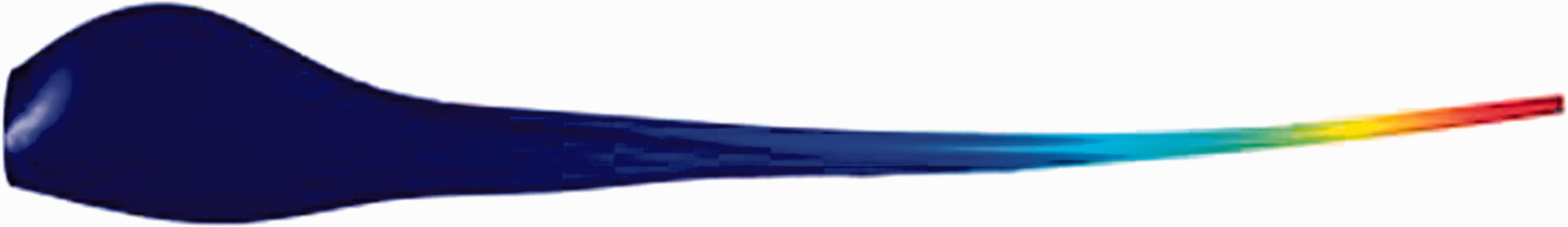
3. Dynamic model of the wind turbine blade with shunt damping
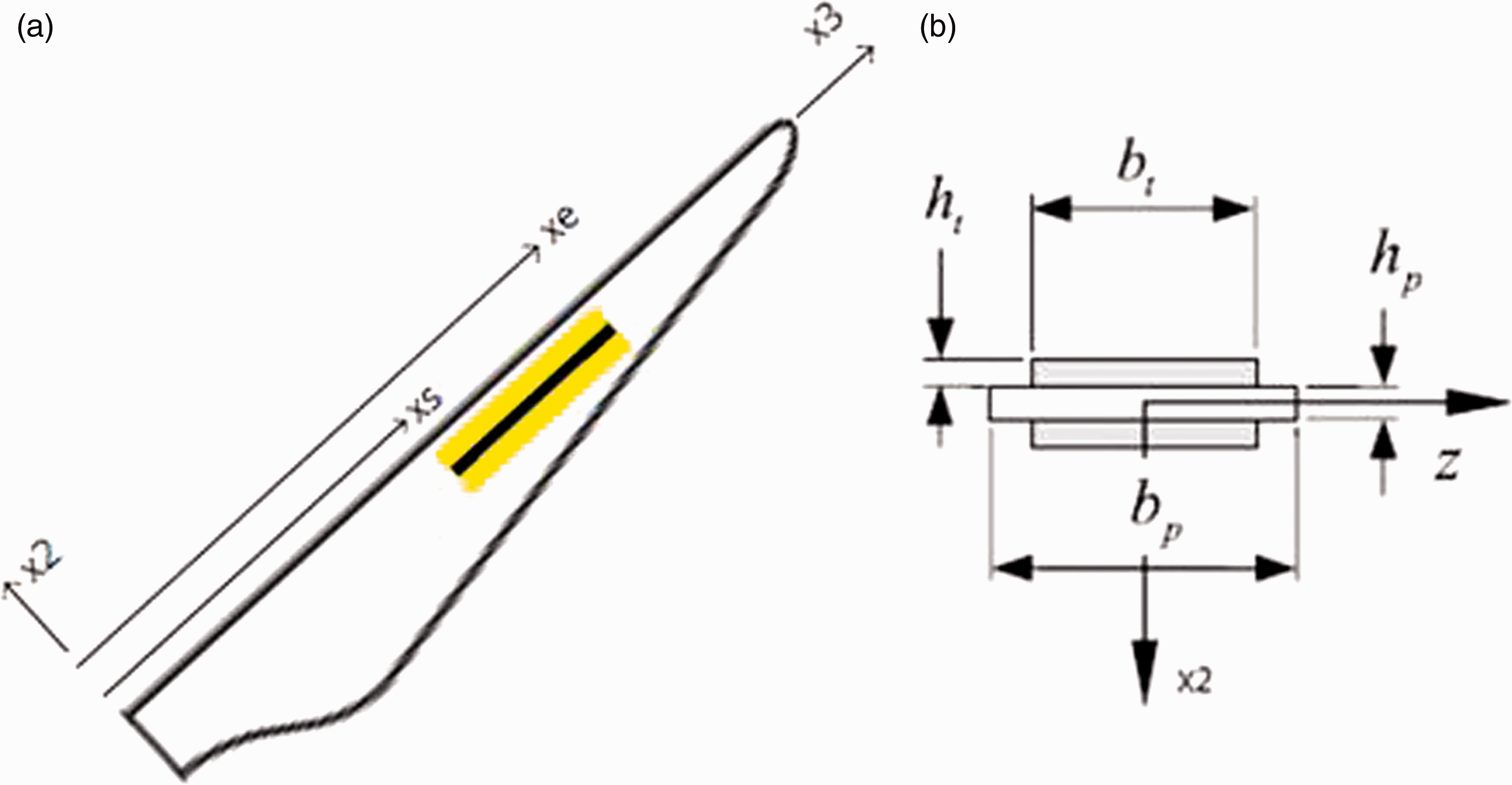
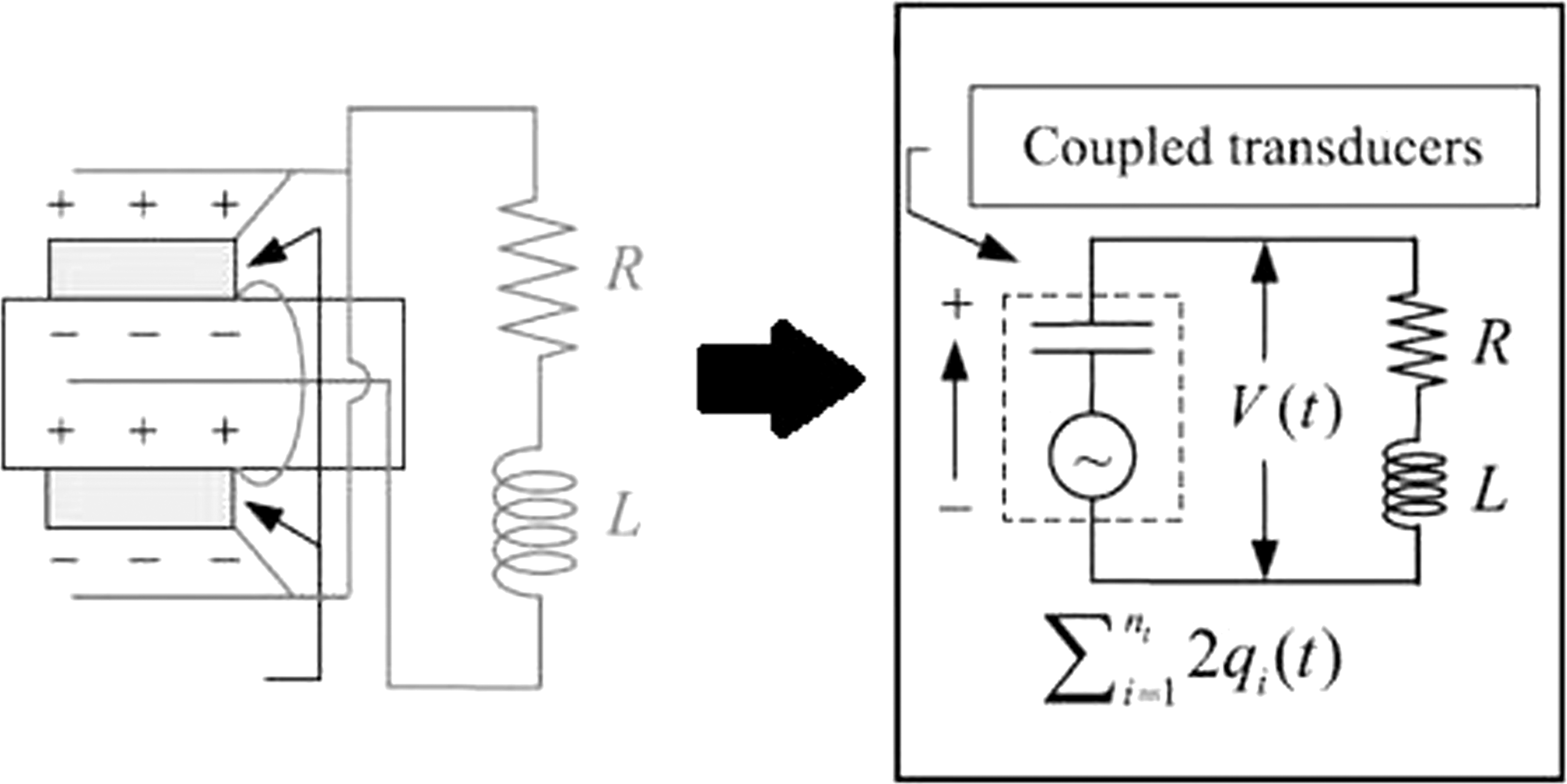
The basis of the shunt damping operation in reducing vibrations is based on the addition of damping to the system (Mao and Pietrzko, 2013). In this paper, to reduce edgewise vibrations of the wind turbine blade, the shunt damping method is proposed. The cut-out view of the blade showing piezoelectric layers as shunt dampers is shown in Figure 10, In Figure 11, geometric variables related to dimensions and position of the plate and piezoelectric layers are shown. In addition, Figure 12 indicates the equivalent circuit of the shunt damper for n pair of piezoelectric layers. The parameters and variables L, R, V, I, and qi represent, respectively, the inductance, resistance, voltage, electric current, and electric charge. Wind turbine blade with a plate mounted in the middle of the blade and piezoelectric layers on its upper and lower surfaces (the yellow color shows the piezoelectric layer and the black color indicates the plate mounted inside the blade). Geometric variables related to dimensions and position of the plate and piezoelectric layers in the blade (a) transversal view (b) sectional view (Sales et al., 2013). Shunt damping equivalent circuit (Sales et al., 2013).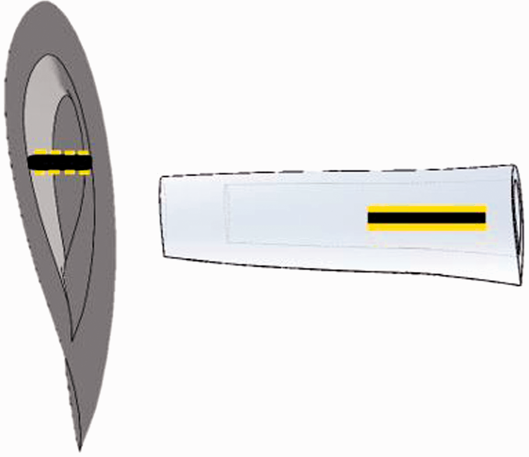
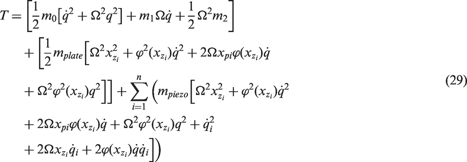
The kinetic energy of the blade, including the plate installed inside the blade and piezoelectric layers, is obtained as follows:
The term for the kinetic energy of the blade is derived from equation (3). Also, kinetic energy related to the plate and each piezoelectric layer is presented as follows:


Also, zi denotes the center of the plate mounted inside of the blade in the longitudinal direction. It is noted that the velocity of the plate and the piezoelectric layers are considered roughly the same as the velocity of their geometric center. In addition, the length of the piezoelectric layers is considered equal to the length of the plate and therefore, the longitudinal position of the center of the piezoelectric layers and center of the plate can be calculated from the following equation:

The potential energy of the blade can be calculated from equation (7). Also, the potential energy of the plate can be calculated as follows:
The relation between the electromechanical terms of the piezoelectric material is obtained as follows (Sales et al., 2013):


The potential energy of the piezoelectric layers is presented as follows (Sales et al., 2013):

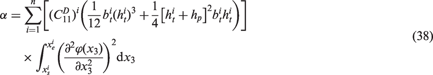


Substituting the equations (7), (31), and (37) into equation (30), the potential energy of the system is obtained as follows:
Using the principle of virtual work (Ginsberg, 2008), virtual work of the system is presented as

The Lagrange equation for the blade displacement is the same as equation (12). Also, the Lagrange equation related to the shunt damping is given by the following equation:
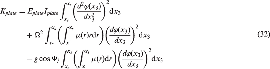
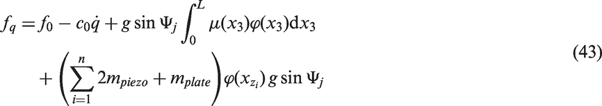
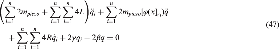
By substituting the kinetic energy (equation (29)), potential energy (equation (41)), generalized forces (equations (43) and (44)) into the Lagrange equations, the final dynamic equations of the blade with shunt damping are obtained as follows: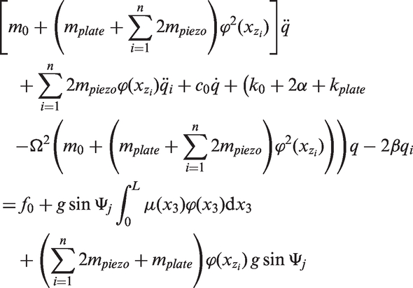
4. Dynamic model of the wind turbine blade with TMD
Figure 13 shows a wind turbine blade with a TMD (including mass, spring, and damper) inside it. TMD inside of a wind turbine blade.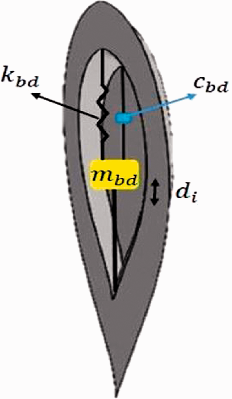
The kinetic energy of the blade with TMD can be calculated as follows:

In the above equation, the index i is related to the location of TMD. The potential energy of the blade with TMD can be calculated as follows:
Using the principle of virtual work (Ginsberg, 2008), virtual work of the system is presented as


5. Optimization
In order to achieve a better comparison of the shunt and tuned mass damping methods, in reducing vibrations of wind turbine blades, the corresponding parameters are first optimized. In this way, the mentioned dampers can be compared with their optimal parameters. In this paper, the optimization of dampers is performed using a genetic algorithm, called nondominated sorting genetic algorithm (NSGA) (Meyarivan et al., 2002).
5.1. Optimization of TMD
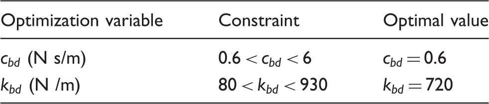
In order to optimize TMD, there are various methods, most of which are based on the research of Sadek et al. (1997). The values of TMD parameters are chosen so that the natural frequency of TMD is equal to one of the natural frequencies (usually the first natural frequency) of the system to reduce the amplitude of the vibrations at this frequency. In this paper, the stiffness constant and damping coefficient of TMD are selected as optimization variables. It is obvious that if the location of TMD is close to the end of the blade, TMD will have better efficiency. However, TMD cannot be located at the end of the blade due to space limitations at the tip of the blade. For the blade considered in this study, TMD can be located from the root to about two-thirds of length of the blade. In order to achieve the highest efficiency, TMD is mounted at a distance equal to two-thirds of the length of the blade from its root. Also, the mass of TMD is considered to be 5% of the effective mass of the blade (i.e. equal to 0.105 kg). There are some relations for optimized values of TMD parameters in various researches (e.g. Sadek et al., 1997). However, most of these relations are based on one degree of freedom dynamic model (an approximate model) of the system. In this study, optimization of TMD parameters is performed based on a more accurate dynamic model of the system (presented in Section 4). In this regard, nominal values for optimization variables (stiffness constant and damping coefficient) are determined based on relations presented in Sadek et al. (1997). Then, from 0.2 up to 2 times of the mentioned nominal values is selected as constraints on optimization variables. The objective function for optimization of TMD is considered maximum displacement at the tip of the blade, which optimization attempts to minimize it. After performing optimization, optimal values for TMD parameters can be determined. Figure 14 shows data produced by the genetic algorithm for optimization of TMD. The obtained optimal values and related constraints are presented in Table 2. Data produced by the genetic algorithm for optimization of TMD. Optimization constraints and optimal values of TMD parameters.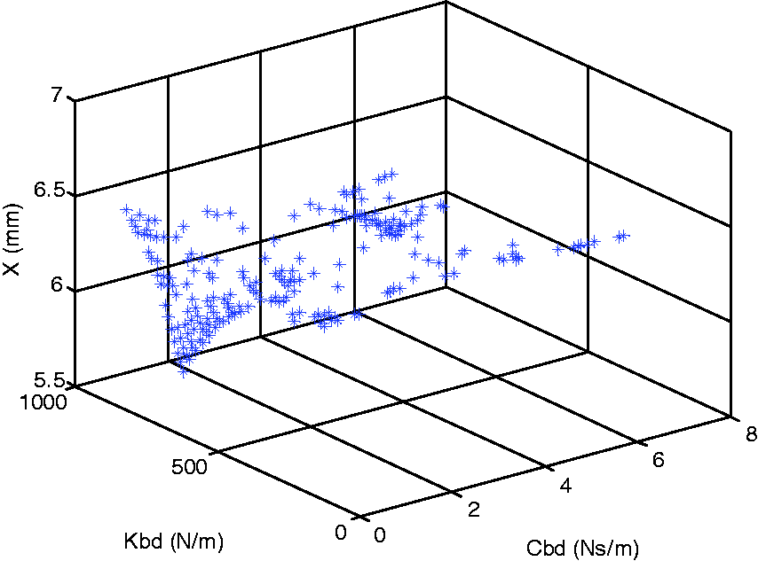
5.2. Optimization of shunt damper
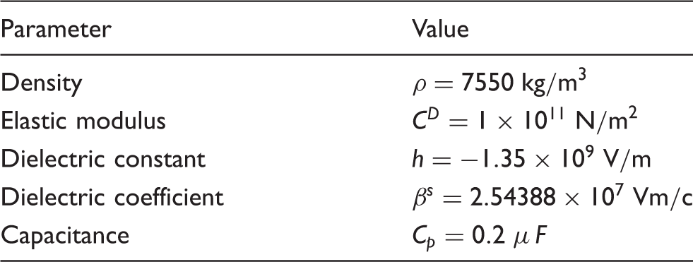
Characteristics of piezoelectric material (Mao and Pietrzko, 2013).
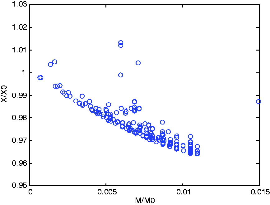
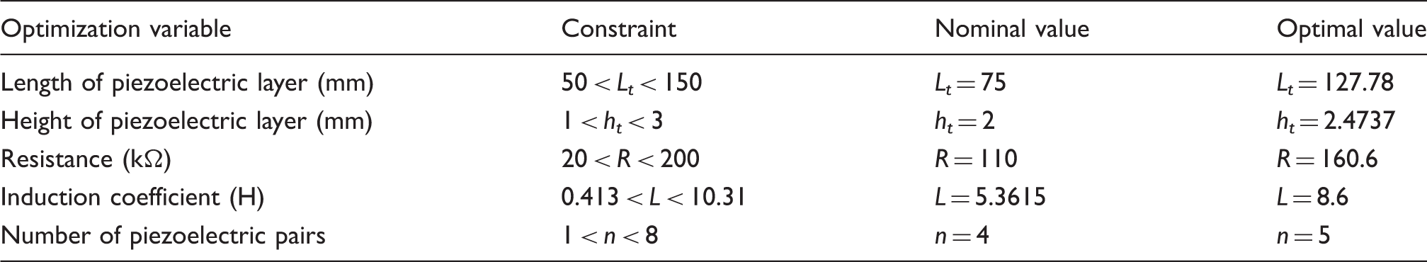
In this study, optimization of shunt damper is performed based on the dynamic model presented in Section 3. It is noted that the shunt damper should not add large mass to the blade (compared with the blade mass). Therefore, the objective function is considered as a combination of tip displacement of the blade and the total added mass of the piezoelectric layers. The optimization attempts to minimize this objective function. The objective function is given as Data produced by the genetic algorithm for optimization of shunt damper. Optimization constraints, nominal and optimal values of shunt damper parameters.
6. Simulation results and discussion
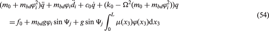
In order to compare the performance of shunt and tuned mass dampers in vibration suppression, the blade with specifications presented in Section 2.2 equipped with the mentioned dampers with optimal parameters (presented in Tables 2 and 4) is considered. The frequency of wind excitation is considered near the first natural frequency of the blade. In this study, wind excitation in the form of a sweep sine wave with linearly increasing frequency from 50 up to 90 rad/s is applied. The dynamic equations of the blade with shunt damping (coupled equations (46) and (47)) are solved numerically using ode45 algorithm (Dormand and Prince, 1980) in the presence of wind excitation. In a similar way, dynamic equation of the blade (equation (13)) and also dynamic equations of the blade with TMD (coupled equations (54) and (55)) are solved numerically. Edgewise vibration at the tip of the blade with and without an optimal shunt and tuned mass dampers in the presence of wind speeds of 5 m/s, 10 m/s, 15 m/s, and 20 m/s are shown in Figures 16, 17, 18, and 19, respectively. Edgewise vibration at the tip of the blade with and without an optimal shunt and tuned mass dampers in the presence of a sweep sine wind excitation with speed of 5 m/s. Edgewise vibration at the tip of the blade with and without an optimal shunt and tuned mass dampers in the presence of a sweep sine wind excitation with speed of 10 m/s. Edgewise vibration at the tip of the blade with and without an optimal shunt and tuned mass dampers in the presence of a sweep sine wind excitation with speed of 15 m/s.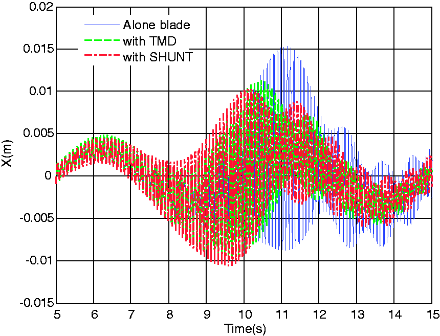
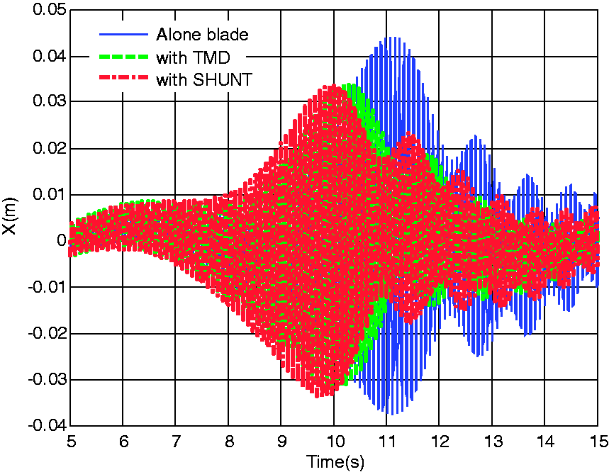
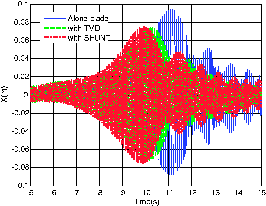
In order to compare vibration suppression of optimal shunt and tuned mass dampers quantitatively, root mean square (rms) of responses in Figures 16–19 are determined. In this way, the percentage of decrease in rms vibration at the tip of the blade can be calculated for various wind speeds and is presented in Table 5. Edgewise vibration at the tip of the blade with and without an optimal shunt and tuned mass dampers in the presence of a sweep sine wind excitation with speed of 20 m/s. Percentage of decrease in rms vibration at the tip of the blade with applying optimal shunt and tuned mass dampers for various wind speeds.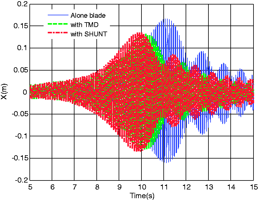
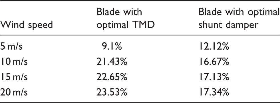
According to Table 5, it is observed that in low wind speeds, shunt damper is more effective than a TMD in vibration reduction of the blade. However, in higher wind speeds, TMD suppresses vibration of the blade more in comparison with the shunt damper.
For a better comparison, frequency response of edgewise vibration at the tip of the blade with and without optimal shunt damper and TMD in wind excitation with speed of 10 m/s is shown in Figure 20. Frequency response of edgewise vibration at the tip of the blade with and without optimal shunt and tuned mass dampers in wind excitation with speed of 10 m/s.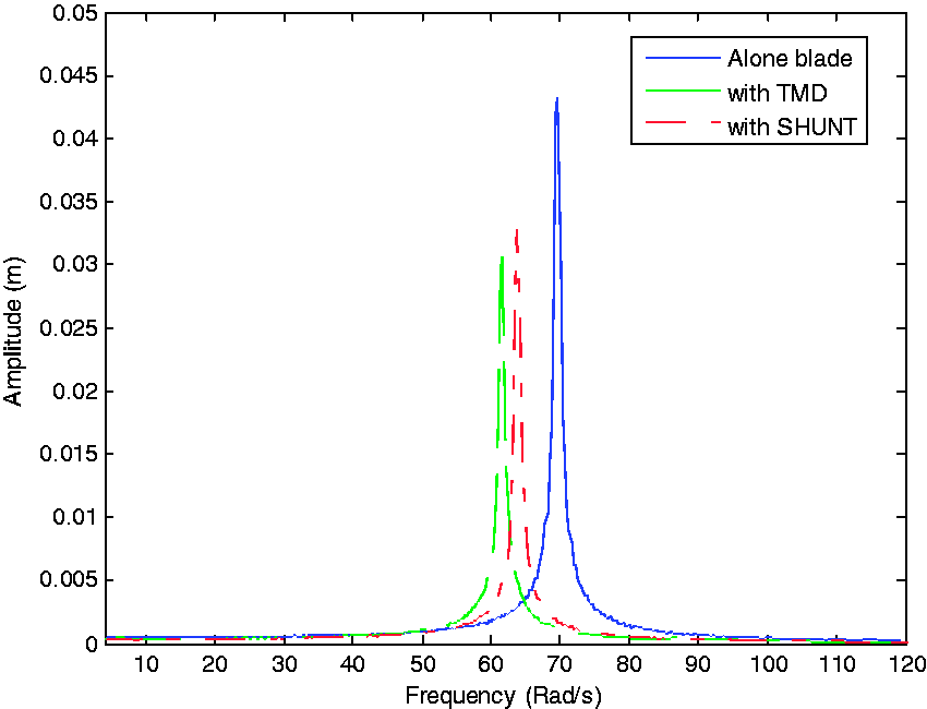
7. Conclusions
In this paper, the shunt damping method was proposed for reducing edgewise vibrations of the wind turbine blade and its effectiveness was investigated and compared with one of the conventional methods called TMD. Simulation results show that in low wind speeds, shunt damper is more effective than a TMD in vibration reduction of the blade. However, in higher wind speeds, TMD suppresses vibration of the blade more in comparison with the shunt damper. In the implementation point of view, the installation of a TMD requires a considerable space inside the blade for its displacement, whereas the implementation of shunt damper only needs a small space for attaching piezoelectric layers.
It is noted that in this study, only the first vibration mode of the blade has been considered and therefore, comparison of TMD and shunt damper has been performed near the first natural frequency of the blade. The authors suggest the mentioned comparison in a wide range of frequencies as a future study. In addition, in this paper, the interference between the nacelle and blade vibrations and also coupling between edgewise and flapwise vibrations has been ignored. Investigation on the coupling effects can be subject of a future study. Finally, in this research, simulation results have been presented. Experimental evaluation of the shunt damping method for vibration reduction of the wind turbine blades is suggested for future research.
Footnotes
Declaration of conflicting interests
The author(s) declared no potential conflicts of interest with respect to the research, authorship, and/or publication of this article.
Funding
The author(s) received no financial support for the research, authorship, and/or publication of this article.