
Abstract
Track assemblies are widely used to reduce vehicles’ ground pressure and improve their off-road performance. During off-road, the track tension has a significant effect on the performance of the crawler driving system. Previous control strategies only make use of the motions of partial road wheels. This paper develops a logical improvement to govern the motion of the track tensioner by using all road wheels. First, a dynamic model of the hydraulic-mechanism coupling system is established using the transfer matrix method for multibody systems and pressure-flow equations. Then, in order to get the angle of the idler arm, a modeling method of wheel envelope perimeter is developed, which is based on the locations of all wheels. Simulation results indicate that the control system maintains the wheel envelope perimeter almost constant while road wheels swing and decrease the possibility of peel-off and breakage of the track. It alleviates the track repeated stretch and keeps the tension in a stable range to reduce the fatigue damage. The control strategy can effectively reduce the peak value of the upper track tension during a vehicle passing through obstacles. This study suggests that the active track tensioning system can be implemented to improve the driving properties of tracked vehicles.
Keywords
1. Introduction
Due to the advantages of powerful traction, low ground contact pressure (Rahman et al., 2007; Zhang and Huang, 2015), strong climbing capacity and small swerving radius, track assemblies have been widely used in military vehicles and engineering machinery. The track tension has an important influence on the performance of the crawler driving system (Huh and Hong, 2001). As the track tension increases, excessive load is generated on tracks and suspension systems. Conversely, if the track tension decreases, sag or peel-off of tracks may happen. In addition, with the constant wear and tear of track rubber bushing elements, the track becomes more slack. Therefore, the track tensioner plays a very important role in the driving process. It adjusts the track tension as appropriate to guarantee the stability of the track ring at all time and then improve its service life and prevent the malfunction of peel-off caused by the excessive vibration and impact.
At present, the torsion arm tensioner is adopted in most tracked vehicles. Track tension is set before the vehicle starts, and the cylinder is locked while driving. Generally, the pre-tension takes 8%–10% of the vehicle weight (Xiao and Li, 2006) and has, for example, three modes: paved-road, cross-country and pivot turning (Huh et al., 2003; Ryu et al., 2003). The choice of pre-tension completely depends on the experience of the driver. However, it may lead to serious problems such as peel-off and breakage of tracks once a misjudgment occurs or the road surface condition changes suddenly.
In view of the above problems, some scholars proposed auxiliary track tensioning systems to adjust the track tension. The M1A1 tank uses a mechanical link between the idler arm and the closest road wheel, where the position of the idler is obtained by the road wheel without considering the track tension. Matej (2013) thought that the motion of the track tensioning element was designed as a function of all the road wheels’ motions and provided the constant coefficients of each road wheel by using the genetic algorithm. However, the tracked vehicle model is too simple and does not consider the mathematical model of the actuator. Huh et al. (2004, 2001) designed a fuzzy logic controller to control the track tension by means of an estimated track tension and considering the highly nonlinear vehicle characteristics. Mȩżyk et al. (2017) assumed a fixed torque which was loading on the idler and originated from a hydraulic cylinder to control the track tension.
At present, due to the development of multibody dynamic software, the dynamic modeling of tracked vehicles has become increasingly sophisticated. However, since this software is based on the usual multibody dynamics method, it is necessary to re-deduce the dynamic equations when the system model changes. The workload is heavy, and the low computational efficiency for complex systems is a serious problem. Rui et al. proposed a transfer matrix method for multibody systems (MSTMM) (Gu et al., 2017; Rui et al., 2017, 2016, 2015), which has the advantages of high programming, low system matrix order and high computational efficiency. It provides an effective approach for modeling of tracked vehicles.
In order to improve ride comfort and achieve significant performance, road wheels always oscillate with the change of the terrain, which may change the wheel envelope perimeter. It will increase the detracking risk and aggravate the track repeated stretch (Lv et al., 2018). On account of the slack of track leading to peel-off (Wong and Huang, 2006), tightening aggravating the wear of the track wheel assembly and reducing the ride comfort, the wheel envelope perimeter should be kept as constant as possible. In this paper, a modeling method of wheel envelope perimeter is developed, which is based on variations in the relative location of each wheel of the wheel system. The position of the idler is actively adjusted according to the position of all road wheels, so as to keep the wheel envelope perimeter almost constant. In this way, the possibility of peel-off caused by excessive impact is reduced, and the track tension can be kept within a relatively stable range. The effect of the control system is evaluated with the mathematical model of a hydraulic-mechanism coupling tracked vehicle system based on the MSTMM and pressure-flow equations. Different types of road profiles are tested to prove the proposed method.
The main contributions of this paper are summarized as follows: The mathematical model of a hydraulic-mechanism coupling tracked vehicle system is deduced. A modeling method of wheel envelope perimeter is developed to govern the motion of the track tensioner by using motions of all the road wheels. The proposed control strategy effectively reduces the deformation of the track rubber portion and keeps the tension in a stable range.
2. Track tension control system
2.1. Track tensioner
A torsion arm tensioner is illustrated in Figure 1(a), and its arrangement principle is shown in Figure 1(b). P0P2 is the oscillating rod, which is hinged with the hull at point P0. P3P2 is the telescopic rod on the hydraulic cylinder, hinged with the hull at point P3. The track tensioner is essentially a swing guide mechanism, which converts the linear motion of the hydraulic cylinder actuator P3P2 into the rotational motion of the torsion arm P0P2 around point P0. Track tensioner (a) and its arrangement principle (b).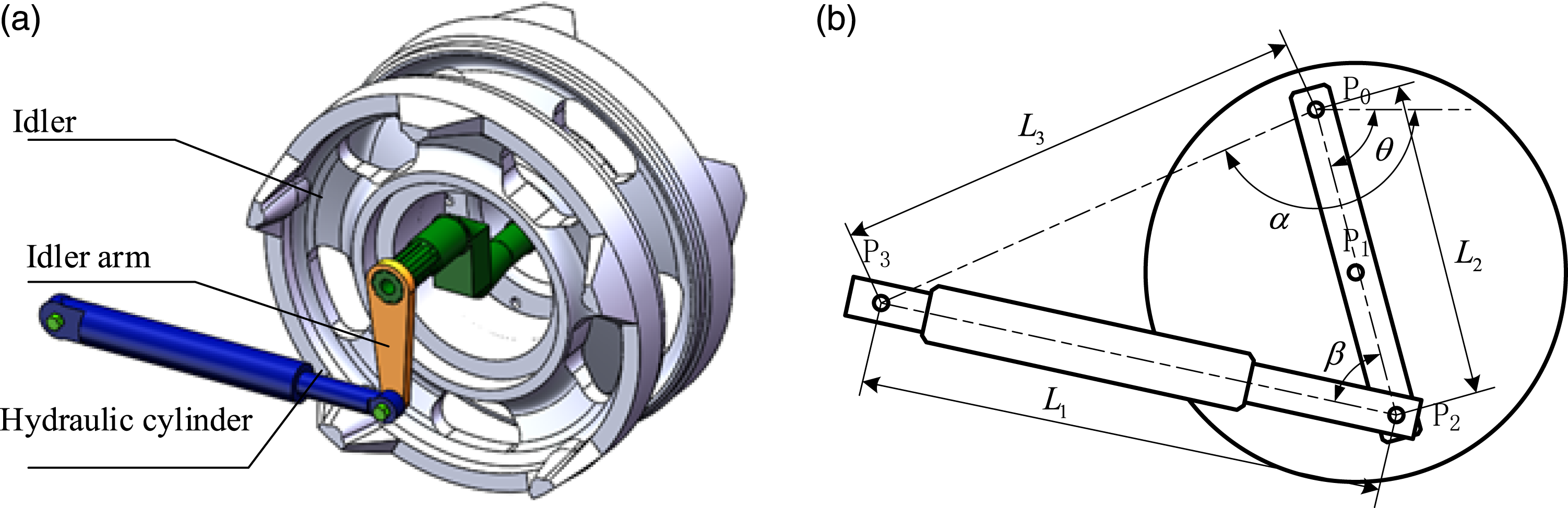
From the law of cosines, we can get

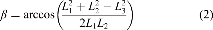
By differentiation w.r.t. time, one may find
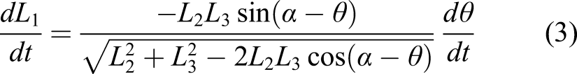
The effective force arm length formed by the hydraulic cylinder piston rod and revolute joint is

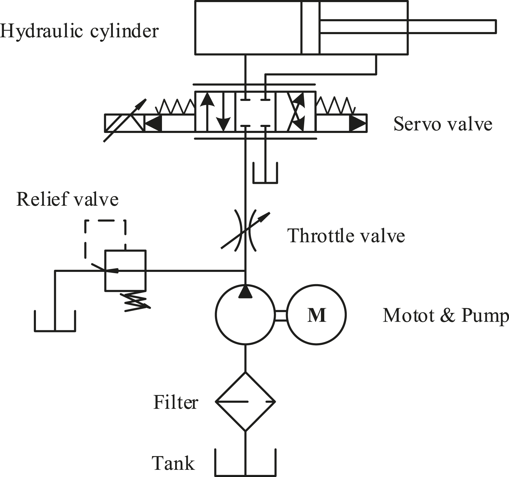
2.2. Hydraulic unit
A hydraulic servo system is selected as the track tension control actuator for the proposed tension control system (Figure 2). The driving force generated by the hydraulic system is applied on the tensioner torsion arm to control the position of the idler. While modeling the hydraulic servo system, the following assumptions are considered: (a) Ignore the pipe losses; (b) The oil temperature and density are constant; (c) The oil supply pressure is constant, and the return pressure is 0; (d) Ignore the nonlinearity of the servo valve; (e) Ignore the influence of friction, transient hydraulic power and other parts of the system on the valve. Configuration of the hydraulic unit.
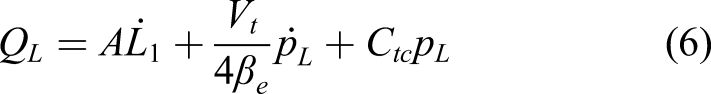
In this paper, the hydraulic system is taken into account in the whole tracked vehicle system. Therefore, the dynamic equation of the hydraulic system is not written separately. Only the hydraulic driving force needs to be deduced. A mathematical model of the plant can be derived from the flow equation of the valve and the continuity equation. The valve-flow-rate equation is highly non-linear and dependent on the valve displacement from neutral, which is proportional to the input voltage

Considering the oil leakage, the total oil flow Q
L
is
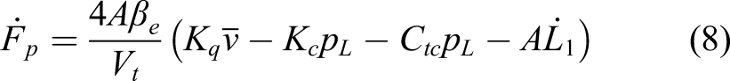
Here, it is assumed that the hydraulic cylinder is symmetrical. The driving force F
p
is

2.3. Wheel envelope perimeter modeling
In order to maintain the track tension within a certain range and improve the service life of the track, the wheel envelope perimeter should be kept as constant as possible. This paper proposes a method for calculating the wheel envelope perimeter with the use of the motions of all road wheels. We analyzed the influence of the position uncertainty of road wheels on the wheel envelope perimeter. The method is further used to match the piston rod elongation and the swing amplitude of road wheels; consequently, the wheel system can keep the wheel envelope perimeter unchanged. The wheel envelope perimeter is divided into two parts: the arc enveloping the wheel and the tangent between two wheels.
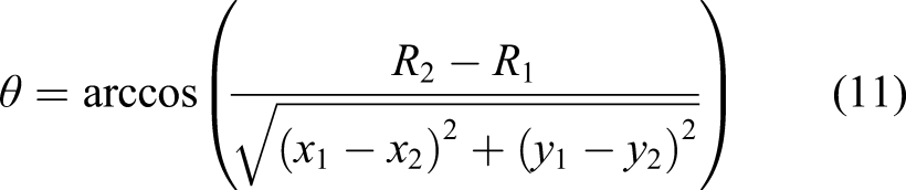
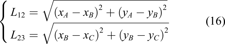
The two adjacent wheels in the wheel system are denoted as w1 and w2 respectively and their centers are (x1, y1) and (x2, y2), respectively. As shown in Figure 3(a), AB is the tangent between two wheels, and one may get The tangent between two wheels (a) and two situations of the track deformation (b, c).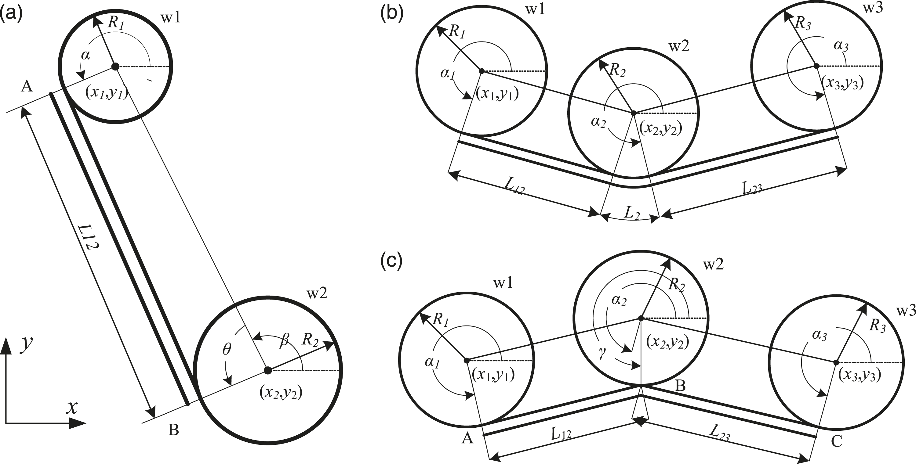


There are two situations of relative positions of the road wheels: 1. When the outer circumference of the middle road wheel is below the lower tangent line of the left and right road wheels, the central road wheel is subsidence. The two track sections between the road wheels can be approximated by straight lines, and there is no intersection between the lines (Figure 3(b)).
The descriptions of
2. When the outer circumference of the middle road wheel is above the lower tangent line of the left and right road wheels. If two deformation parts are still represented by tangents, the two line segments cross under the middle wheel. Take the middle point as shown in Figure 3(c).

A and C are the tangent points between the track and w1 and w3, respectively. B is the contact point between the track and w2
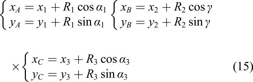
Then, we may obtain
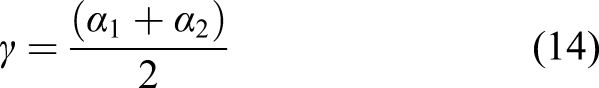
If the positions of road wheels are determined, the wheel envelope perimeter is only related to the rotation angle of the idler arm (Figure 4). Define the wheel envelope perimeter as L, and then Wheel envelope perimeter and the rotation angle of the idler arm.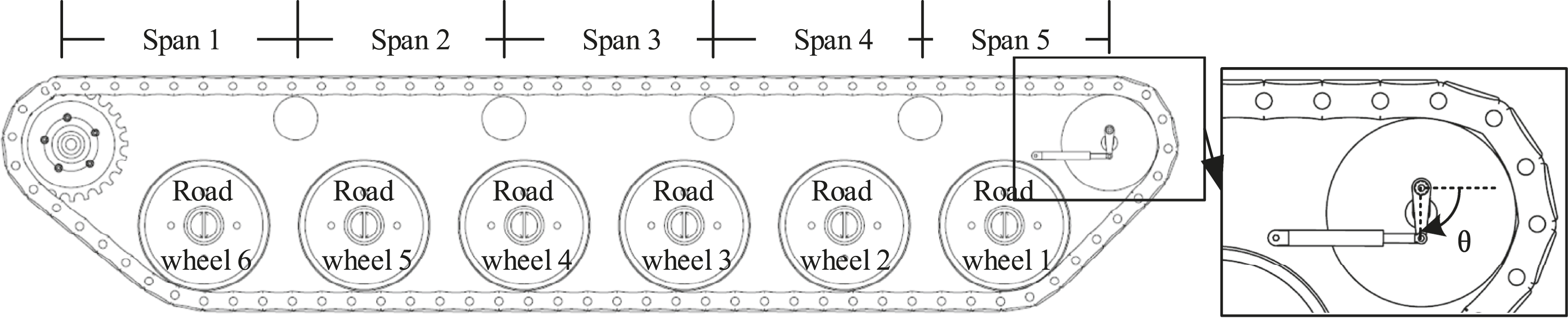

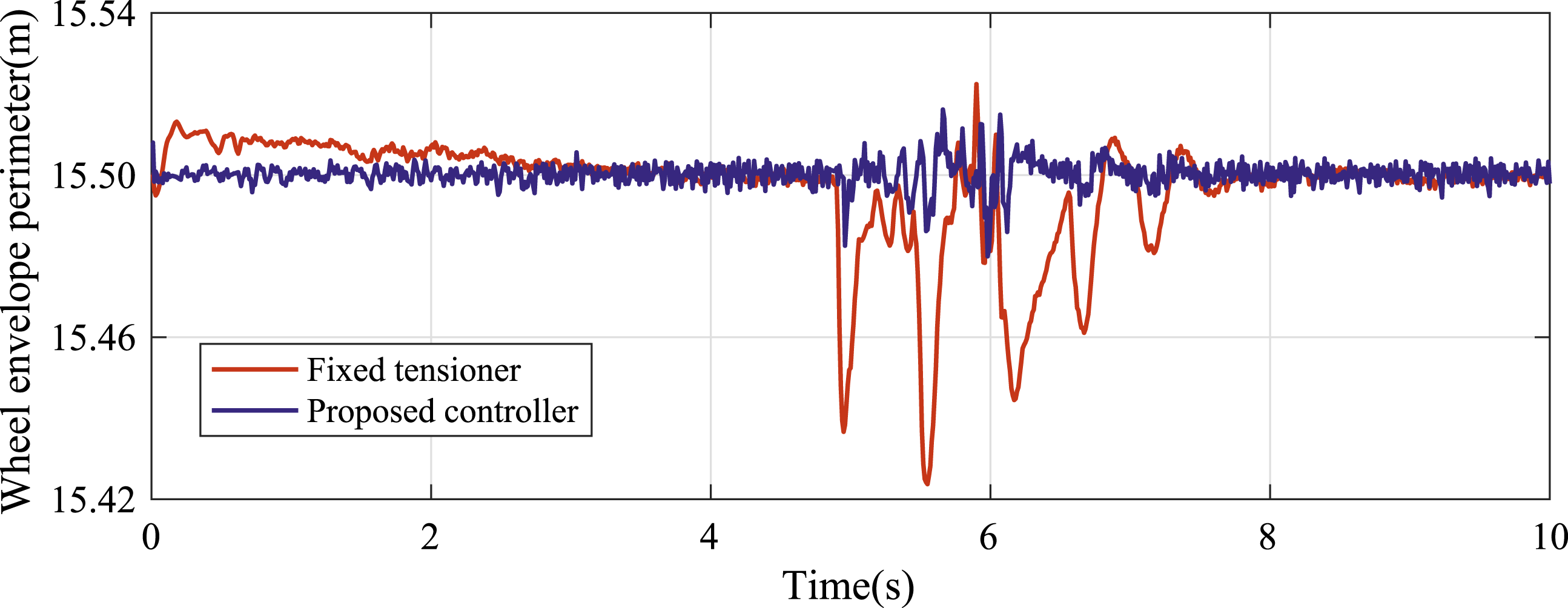
In the initial time, L0 = 15.50 m.
After the positions of the road wheels are measured by sensors, the reference rotation angle of the idler arm is calculated as follows: Calculate the maximum If
3. Numerical model
3.1. Dynamic modeling of the tracked vehicle
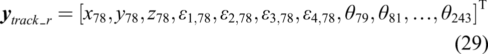
The tracked vehicle consists of a chassis and two track subsystems with a dynamic model as shown in Figure 5(a). Its topology is illustrated in Figure 5(b). The chassis subsystem includes a hull (1), sprockets (54, 66), support rollers (61–64, 73–76), idlers (65, 77), road arms (26–31, 33–38), road wheels (55–60, 67–72) and tensioners (32, 39). The sprockets, support rollers, and road arms are connected to the chassis by revolute joints (2–25, 40–53). In particular, the tensioner is simplified as a torsion arm, and the idler is connected to the chassis through it. A track subsystem consists of 84 track shoes (78, 80, …, 244), where adjacent track shoes are connected by revolute joints (79, 81, …, 245) (Choi et al., 1998). Because track shoes are generally made of steel, they are modeled as spatial rigid bodies. The mass of a track shoe is 28.1 kg. The body-fixed frame of a track shoe is shown in Figure 5(a). The parameters of these track shoes are identical, where the coordinates of the mass center and the output point and the moment of inertia relative to the mass center in the body-fixed frame are as follows. Tracked vehicle (a) and corresponding topology (b).
The elastic-damping model is adopted for the contact between wheels and track shoes (Lee et al., 1998). It should be noted that the driving force generated by the hydraulic system is applied to the idler arm as an external torque. Its value can be obtained by the following formula.

According to the dynamic model and topology of the chassis subsystem, the transfer equation of the chassis subsystem can be obtained based on the automatic deduction theorem (Rui et al., 2015) as


On the right track subsystem, the revolute joint 245 is cut off and its effect on the closed-loop multibody system is treated as an elastic-damping model. In this way, the track subsystem is processed into an open-loop system by a closed-loop system. The transfer equation is


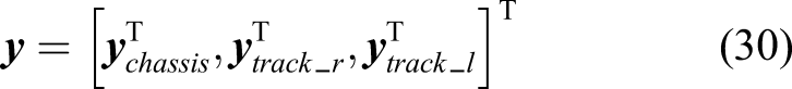
For the chassis subsystem, the output of body element 1 is selected as the reference point. Its generalized coordinates are the position coordinates and Euler parameters of this reference point in the inertial frame and relative rotation angles of all revolute joints, i.e.

For the right track subsystem, element 78 is selected as the base element. Similar to the chassis subsystem, its generalized coordinates are
The generalized coordinates of a tracked vehicle system are
The generalized coordinates and velocities

Here, the generalized accelerations
Seen from the above solution process, for a chain system, the overall transfer matrix is the continuous multiplication of the transfer matrix of each element from the beginning to the end of the chain. Owing to the extreme low order of the system matrix, the calculation speed is extremely high. In Gu et al. (2017) and Rui et al. (2017, 2016, 2015), the comparisons of computational precision and speed between the MSTMM and other dynamics methods can be found.
3.2. Simulation process of the active track tensioning system
In order to achieve the real-time tension control of tracked vehicles, the reference rotation angle Block diagram of the active track tensioning system.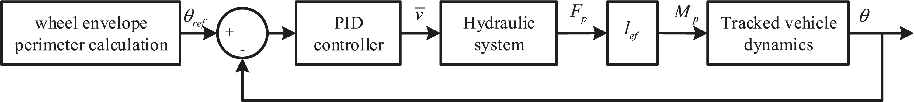
In order to test the running conditions of the tracked vehicle in the process of passing obstacles, a road surface with four triangular obstacles (Figure 7(a)) is used. The front 50 m is a flat road, enabling the tracked vehicle to accelerate from 0 km/h to 30 km/h, and the total simulation time is 10 s. Road surface: obstacles (a) and D-grade (b).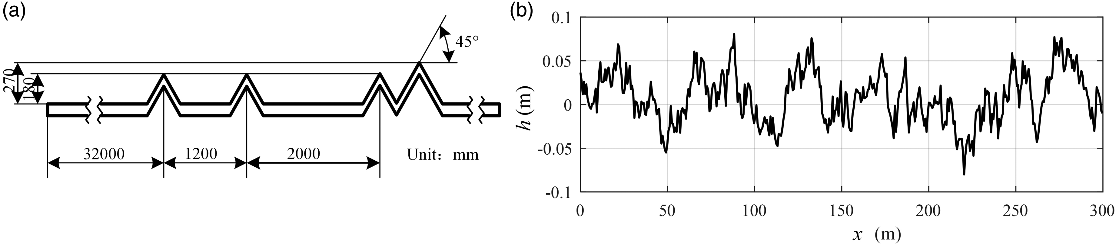
To prove the proposed method, a stochastic road for test is necessary. The variation of road height h(x) is reconstructed with a harmonic superposition method. It can be performed with different forms of triangular series. Select a certain array h(xi) from several generated arrays as the road profile. Based on D-grade, a 200 m running road is simulated, as shown in Figure 7(b).
4. Simulation results
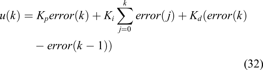
In this section, the simulation was carried out with respect to two road conditions, respectively. The proposed control method in this paper was compared with the fixed tensioner and the controller in Huh et al. (2004), respectively. The differential equations of the tracked vehicle can be solved by using a fourth-order Runge–Kutta numerical integration method. The genetic algorithm is applied to find the PID coefficients, where for the right tensioner, Kp = 9.945 × 10⁻², Ki = 1.247 × 10⁻⁴ and Kd = 1.967 × 10⁻⁴, and for the left tensioner, Kp = 8.327 × 10⁻², Ki = 6.901 × 10⁻⁵ and Kd = 8.712 × 10⁻³. The sampling time is decreased to 0.02 s for wheel envelope perimeter calculation.
4.1. Simulation of the tracked vehicle passing obstacles
Figure 8 presents time dependent charts of rotation angles of idler arms. As a result, the wheel envelope perimeters in time are shown in Figure 9. Compared with the fixed tensioner, this solution allows a significant decrease of the variance of the wheel envelope perimeter. A slight shaking appears and causes a sudden change of the wheel envelope perimeter when the vehicle starts. It can be seen that the control system quickly adjusts the wheel envelope perimeter to 15.50 m. Due to the delay of the hydraulic system, the wheel envelope perimeter cannot be constant all the time; especially when the vehicle is over obstacles, the road wheel positions change drastically. However, the control system still makes its scope narrower to a smaller extent. Comparison of simulation and reference rotation angles of the right (a) and the left (b) idler arm. Cure of wheel envelope perimeters.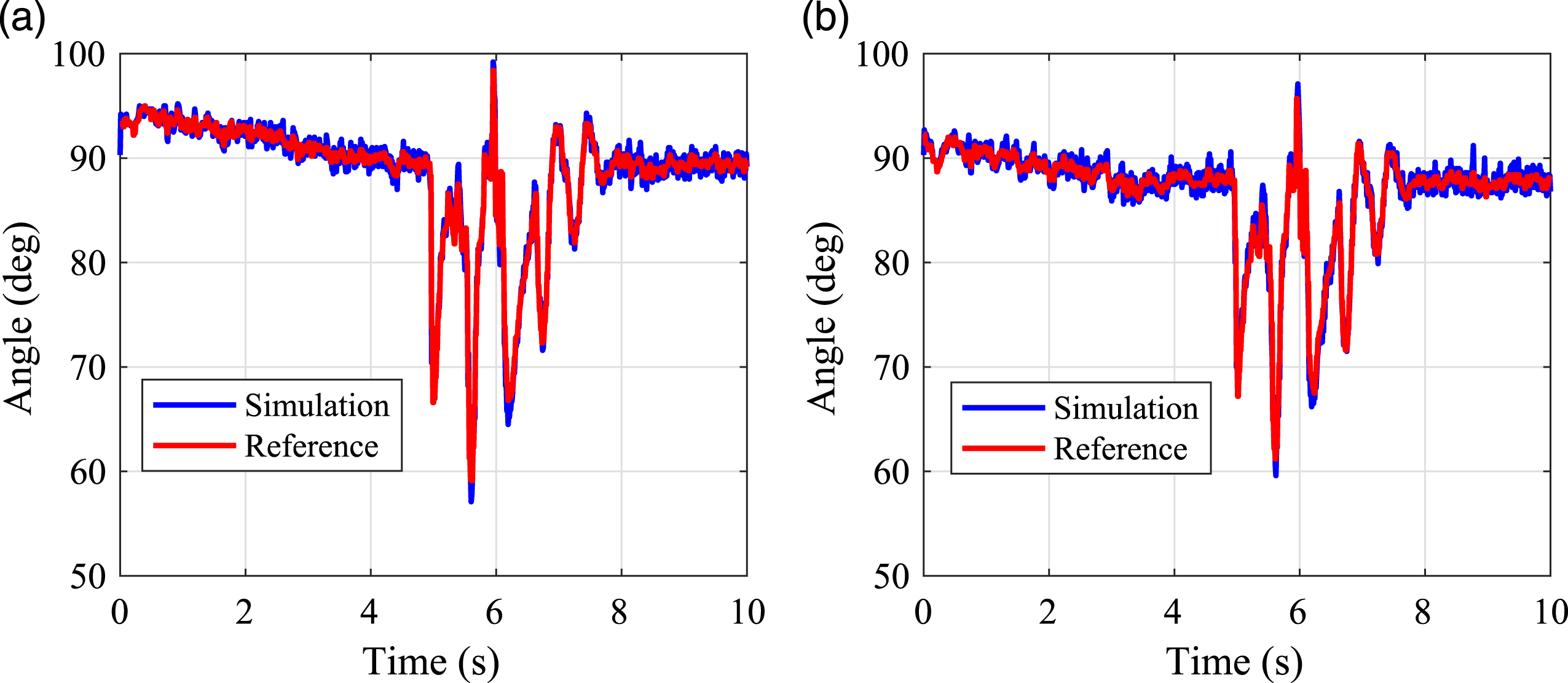
The closed-loop transfer functions of the left and right controller are
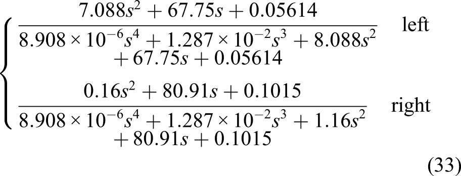
The real parts of their characteristic roots are all negative, so these two systems are stable.
For a hydraulic system, its flow-gain coefficient K
p
, flow-pressure coefficient K
c
and leakage coefficient C
tc
are uncertainties. Here, K
p
is increased by 50%, K
c
reduced by 50% and C
tc
increased by 100%, respectively. Their rotation angles of right idler arms are presented in Figure 10. Obviously, the controller still has a good tracking effect after the parameters change. Rotation angles of the right idler arm with different parameters: (a) K
p
+50%, (b) K
c
−50% and (c) C
tc
+100%.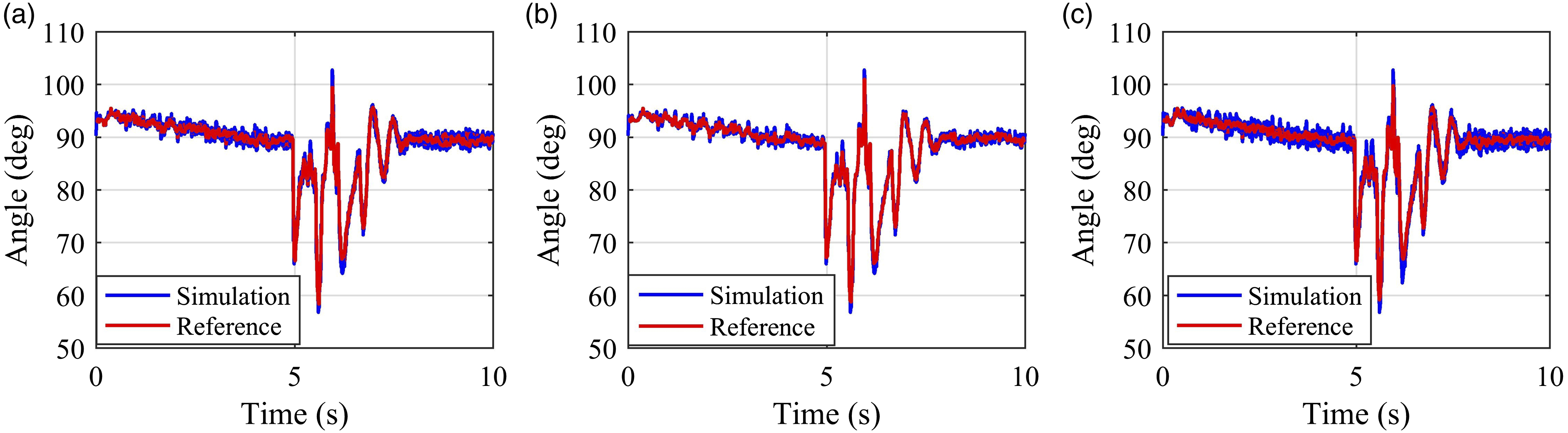
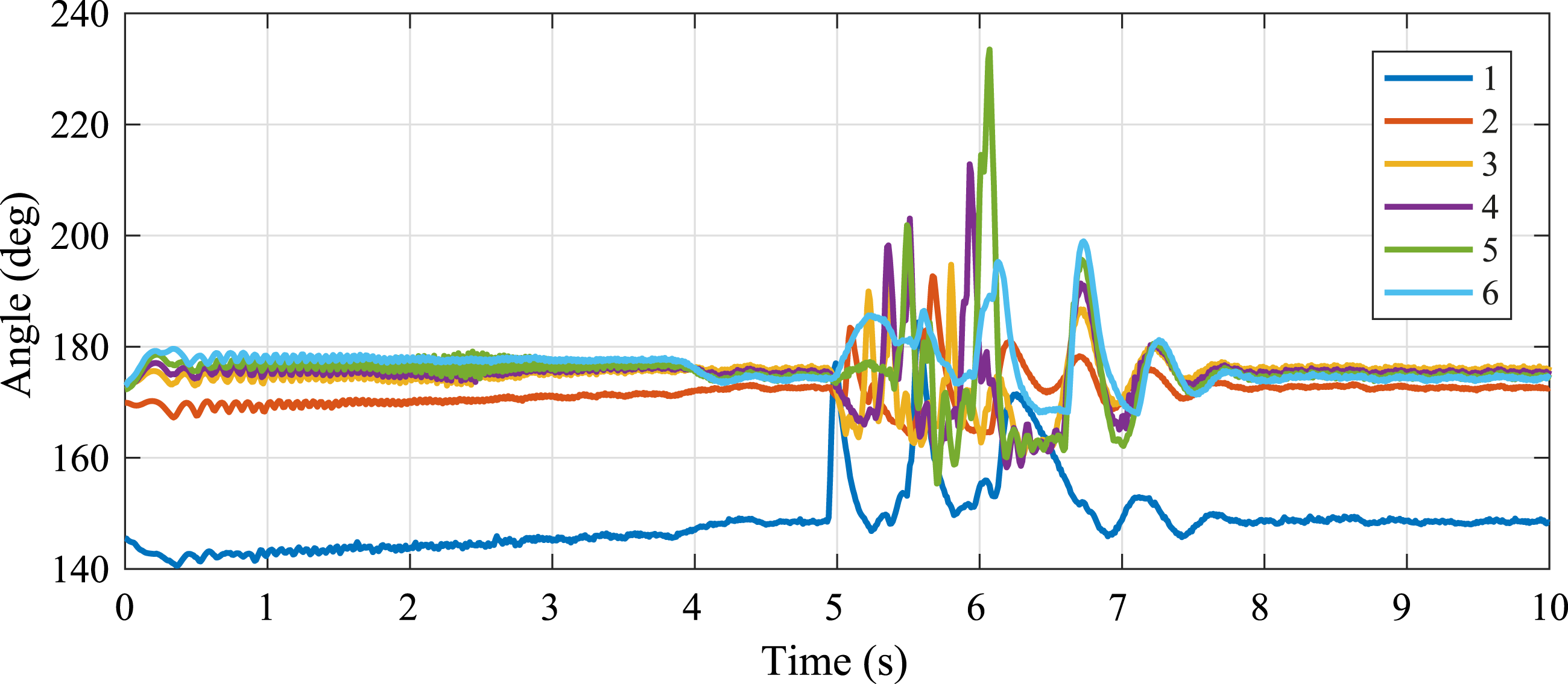
A screen shot of animation of the right track ring in the moment of passing obstacles is shown in Figure 11(a). While the vehicle passing obstacles, road arms swing sharply (Figure 12), causing the right idler arm to swing sharply. After the vehicle passes through obstacles, it bounces on the ground, which explains why the road arms and idler arms still swing greatly between t = 6.5 and 8 s. Screenshots of the right track subsystem with active tensioners (a) and fixed tensioners (b). Rotation angles of road arms 1–6.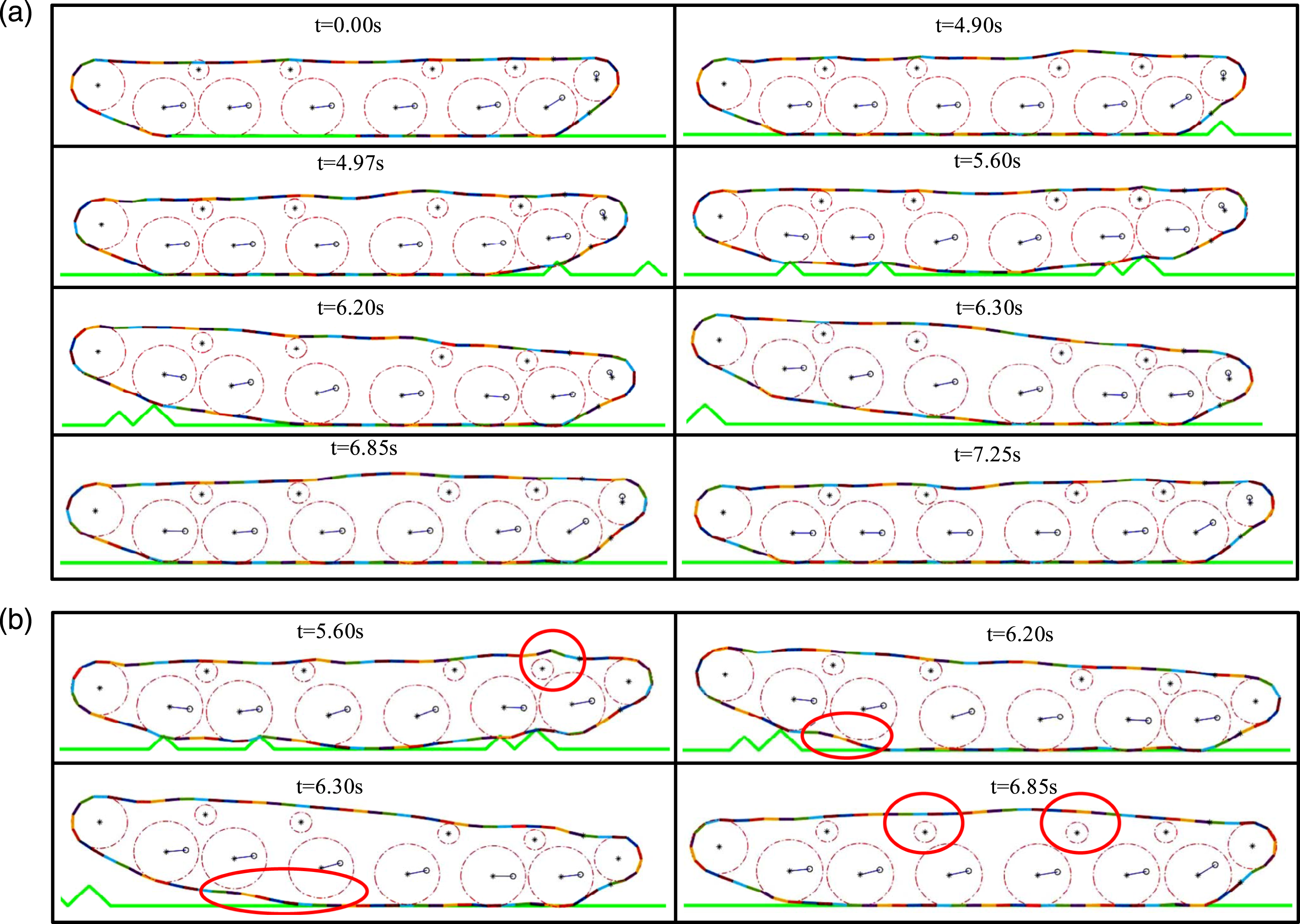
As a comparison, a screen shot of animation of a vehicle with fixed tensioners is presented in Figure 11(b). As indicated by the circles in the figure, the track shoes are separated from wheels while the vehicle passing obstacles. Correspondingly in Figure 11(a), due to the active track tensioning system, the track shoes are always in contact with wheels, which reduce the possibility of peel-off.
As shown in Figure 4, the upper span of the track is divided into five segments by support rollers. The tension variations of these five segments are exhibited in Figure 13. Obviously, when the vehicle passes obstacles (t = 5–6 s), the tension of the upper track increases sharply. Compared with the estimated track tension controller (Huh et al., 2004), the control method proposed in this paper can effectively reduce the peak value of the tension during the obstacle crossing. The reason for this result is that the estimated track tension controller only uses the motion of the first road wheel, while the control method in this paper uses the motions of all the road wheels. Tension variation of each track segment: (a) span 1; (b) span 2; (c) span 3; (d) span 4; (e) span 5.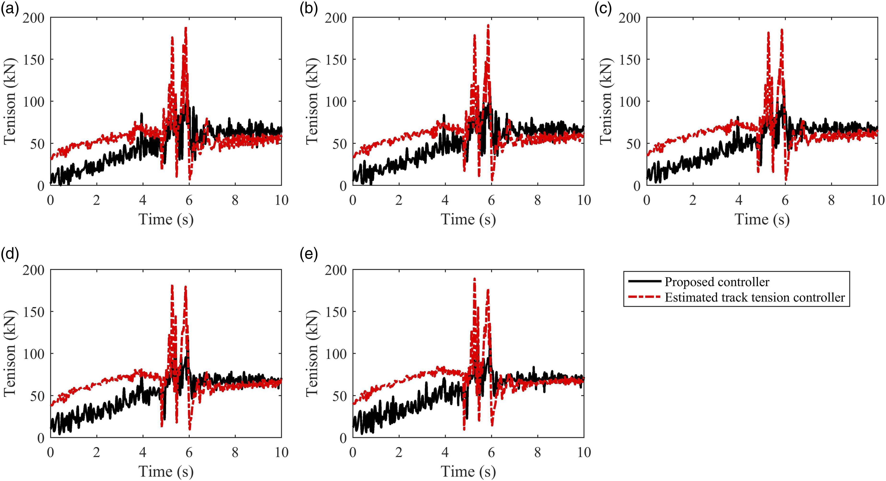
Besides the track tension, the ride comfort is also important. We also selected the vertical displacement and acceleration of the center of mass of the chassis as comparison indexes. The results are illustrated in Figure 14. There is almost no difference. Therefore, the active track tensioning system does not increase the vibration of the chassis. It has no negative effect on the ride comfort. Cure of vertical displacement (a) and acceleration (b) of the center of mass of the chassis.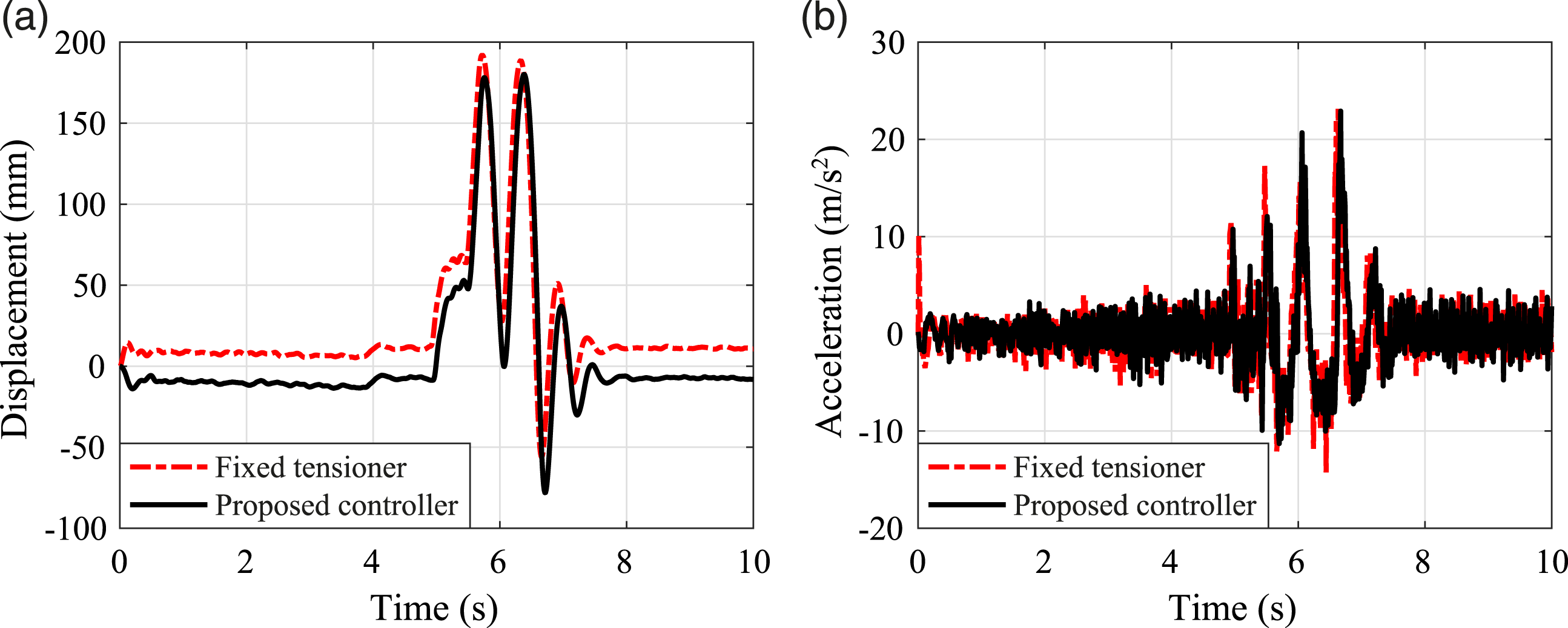
4.2. Simulation of the tracked vehicle running on the D-level road surface
Taking into account the randomness of the driving condition, while the vehicle running on the D-level road surface, the selected driving speeds of the vehicle are 10 km/h, 20 km/h, 30 km/h and 40 km/h. The distributions of wheel envelope perimeters are shown in Figure 15. Through the adjustment of the active tensioning system, the wheel envelope perimeters stabilize at 15.50 ± 0.005 m. The wheel envelope perimeter variations with a fixed tensioner are larger than that with an active track tensioning system. In addition, for the vehicle with fixed tensioners, the wheel envelope perimeters decrease slowly with the increase of the driving speed. In contrast, the active tensioning system can control the wheel envelope perimeters to remain stable regardless of the speed of the vehicle. Distributions of wheel envelope perimeters at different driving speed. (a) v = 10 km/h; (b) v = 20 km/h; (c) v = 30 km/h; (d) v = 40 km/h.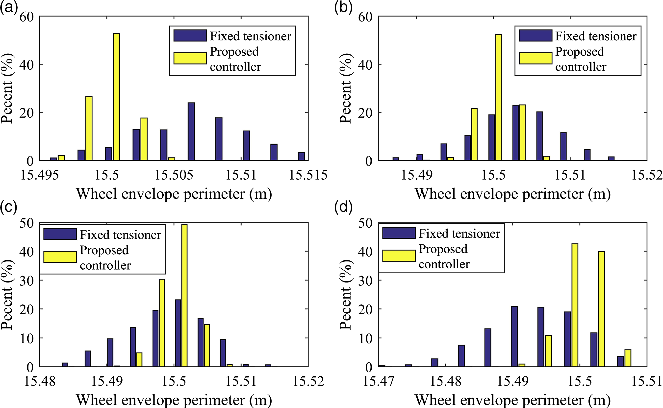
5. Conclusions
This paper investigates an application of the active track tensioning system to control the track subsystem. Based on the proposed modeling method of wheel envelope perimeter, all road wheels are used to govern the motions of tensioners. The tensioner is actuated by a hydraulic system with a PID controller. The mathematical model of a hydraulic-mechanism coupling tracked vehicle system based on the MSTMM and pressure-flow equations is established. The genetic algorithm is applied to find the PID coefficients. The effectiveness of the proposed track control system is verified by simulating a tracked vehicle passing obstacles. Simulation results indicate that the active track tensioning system can maintain the wheel envelope perimeter almost constant while road wheels swing, so that the possibility of peel-off and breakage of the track decreases. Keeping the wheel envelope perimeter constant can effectively reduce the axial deformation variations of the rubber bushing elements and further prolongs the lifespan of the track. In addition, the solution decreases the variance of the track tension to reduce the fatigue damage while the vehicle passing obstacles. Compared with the control strategy of using motions of partial road wheels, the control method proposed in this paper can effectively reduce the peak tension of the upper track.
Footnotes
Declaration of conflicting interests
The author(s) declare no conflict of interest in preparing this article.
Funding
The author(s) disclosed receipt of the following financial support for the research, authorship, and/or publication of this article: The authors are grateful for the support from the Science Challenge Project (No. TZ2016006-0104) and Natural Science Foundation of China (No. 11472135).