
Abstract
This study addresses the possibility of adopting semi-active magnetorheological elastomers–based isolators for protecting lightweight structures from ground vibration. The exploitation of these smart devices has the main advantage of controlling their stiffness and damping features by acting on the magnetic field generated by a coil on the basis of the actual conditions of both the lightweight structure and the surrounding environment. This allows for combining the reliability of passive devices with the benefits of active control methods. Both mechanical and control system designs could play a crucial role in the challenging problem of improving isolation performances. To solve this issue, we (i) suggest a novel ball transfer unit–magnetorheological elastomer–based isolation system prototype to obtain an improved isolation response of the lightweight structure with respect to the exclusive use of an magnetorheological elastomer and (ii) propose a novel robust combined neural network and model-predictive control approach, allowing proper functioning of the ball transfer unit–magnetorheological elastomer–based isolation system. The effectiveness of the proposed semi-active isolator in guaranteeing vibrational isolation of lightweight structures is evaluated by considering a rack cabinet composed of three storeys and subject to an El Centro earthquake. Numerical simulations confirm and disclose the efficacy of the proposed approach.
Keywords
1. Introduction
Isolating lightweight structures (e.g. rack, shelters, and works of art) from ground vibrations (originated, e.g. by earthquake) with the aim of protecting them against hard acceleration and ensuring their correct operation is very important. Traditionally, vibration isolation is achieved via passive isolators that allow for shifting the system’s natural frequencies far away from the forcing frequencies to avoid mechanical resonance (Kelly, 1986). To obtain an effective isolation system, it is necessary to ensure that the ratio between the lowest forcing frequency and the natural frequency is greater than about 3. More specifically, in the presence of random vibrations (e.g. excitation due to earthquake, vehicle traffic, and sea waves), to isolate a wide range of frequencies, the structures must have low natural frequency (e.g. in the seismic field, the tendency is to realize a horizontal natural frequency in the range of 0.25–0.50 Hz) (Warn and Ryan, 2012). This can be achieved by adopting elastomeric isolators characterized by a low shear modulus or subjected to high vertical pressure (Higashino et al., 2003). However, for lightweight structures, the exploitation of this kind of passive isolators is not suitable because to achieve high pressure values, it would need too small isolator cross-sectional areas affected by buckling problems. As an alternative solution, semi-active isolators based on magnetorheological elastomers (MREs) may be adopted (Kallio, 2005; Li et al., 2014). The main advantage of using them consists in controlling their stiffness and damping features by acting on the magnetic field generated by a coil on the basis of the actual conditions of both the lightweight structure and the surrounding environment. This allows combining the reliability of passive devices with the benefits of active control methods (Gent, 2012; Song et al., 2015).
The MRE-based isolation system requires (i) coils and power supplies to generate the magnetic field, (ii) sensors to detect the motion of the structure, and (iii) a control system to adjust the magnetic field intensity on the basis of the motion conditions of the structure. The latter plays a crucial role in enhancing the isolation performances by determining the proper magnetization current to be imposed on the MRE-based isolation system to adapt to its stiffness and damping properties. However, because the behaviour of the isolator is a strongly nonlinear function of both the magnetization current supplied by the coil and the relative displacement amplitude, the designing of adequate control approach is still a challenge (Gu et al., 2017).
With respect to the control perspective, first attempts include an on–off control algorithm (see e.g. Liao et al., 2011; Zhu and Rui, 2014) that, on the basis of the measured structure displacements, changes the MRE stiffness to either a high or a low value. A Lyapunov-based control strategy is, instead, proposed in Behrooz et al. (2014a) and (2014b), where the magnetization current is determined via the minimization of the acceleration and displacement responses of the structure under earthquake. A clipped-control algorithm is also proposed in Opie and Yim, 2011, where a combined H2/linear quadratic gaussian (LQG) approach is exploited for calculating the desired control force to be imposed on the structure, whereas a voltage selection algorithm, leveraging the measurements of the feedback actuation force, generates the voltage control command to drive the MRE isolator. However, in all the aforementioned control strategies, the control input (current or voltage) can only be set either to its maximum or its minimum value. This entails the arising of the chattering phenomenon, which causes periodical acceleration and jerk peaks in the structure responses, especially in the case of fast dynamics (Nguyen et al., 2018b).
To face this issue, alternative control techniques, able to provide a continuous control input, are proposed in the literature. For instance, Nguyen et al. (2017a), (2017b), and (2018a) propose fuzzy semi-active control strategies that, based on the viscoelastic characteristic of the MRE, compute a continuous magnetization current that adapts to its stiffness and damping for minimizing the movement of the isolator. Again, Yang et al. (2016) proposed a fuzzy controller that, based only on the real-time dynamical responses of the building floors, determines the proper magnetization current to impose on the MRE device for minimizing the relative displacement of each floor of the building itself. Although good vibration isolation performances are obtained, fuzzy control–based approaches compute the MRE control input only, leveraging real-time measurements of both displacements and velocities of the structure to be isolated, without considering the dynamical behaviour of the MRE-based isolation system. In addition, uncertainties (such as structural parameters and material inhomogeneity) and external disturbances could affect the isolated structure (Du et al., 2004). As a consequence, these controllers may exhibit unsatisfactory isolation performances because of significant structure excitation or actuator nonlinear effects (Nguyen et al., 2018b).
To overcome this problem, many works on MR dampers suggest using the isolator dynamical inverse model in the control system design phase (Boada et al., 2018; Nguyen et al., 2017a, 2017b). Specifically, the aim was to find the existing relationship between the magnetization current and the actuator force for generating a proper control command to drive the MRE-based isolator. In this direction, to generate the required control input, Gu et al., (2017) and Nguyen et al., (2018b) realize a two-stage control action characterized by (a) a primary controller that determines the required actuation force to impose on the structure and (b) a secondary control action that, on the basis of the inverse isolator dynamical model, generates the required magnetization current that is able to drive the semi-active devices to provide the primary control action.
Specifically, Gu et al., (2017) suggest the classical linear quadratic regulator (LQR) as the primary action and an inverse isolator model, based on general regression neural network (GRNN), as the secondary one. Herein, the proposed novel GRNN only requires six input variables, that is the measured displacements, velocities, and the computed desired shear force at present and one previous time instant, which will result in much less delay tolerance in real-time control. However, the proposed primary control strategy is not robust with respect to uncertainties and external disturbances. Conversely, Nguyen et al., (2018b) propose as a secondary control action an analytical inverse dynamical model of the isolation system that is derived assuming that in the MRE model, only the stiffness spring is variable, whereas the viscoelastic force is uncontrollable. However, because of the strong nonlinear and hysteretic nature of the semi-active device, it is not feasible to obtain an analytical general inverse model for the MRE-based isolation which is able to completely describe its dynamical behaviour in all the different operating conditions (Gu et al., 2017). Regarding the primary control action, a robust sliding-mode controller is proposed.
In addition to the control system design, the mechanical design of the MRE-based isolation system also plays a key role. Indeed, to further improve the isolation performances with respect to the case of lightweight structures, the use of a ball transfer unit (BTU) rolling device can be considered very suitable because of the low weight of the structures involved (Brancati et al., 2018; Brancati et al., 2019a, 2019b).
Based on the previous considerations, the aim of this study is mainly twofold. First, we present a novel ball transfer unit–magnetorheological elastomer (BTU-MRE)–based isolation system prototype for obtaining an improved isolation response of the lightweight structure with respect to the exclusive use of MRE. Second, we propose a novel combined neural network (NN) and model-predictive control (MPC) approach for the BTU-MRE–based prototype. The overall semi-active isolation system combines the robustness of the MPC with the predictive behaviour of NNs, hence allowing very good performances for the isolation of lightweight structures. Indeed, the MPC guarantees the ability to adapt to different environmental conditions, satisfying at the same time all the additional linear and nonlinear constraints on the achievable control effort, and its possible variation, at the current time slot and then optimizing it again, repeatedly, whereas the NN-based inverse model is able to catch the overall nonlinear dynamical effects of the appraised insulation system.
To evaluate the effectiveness of the proposed semi-active insulation system in guaranteeing vibration isolation, we consider a rack cabinet composed of three storeys and subject to an El Centro earthquake. Numerical simulations are carried out to disclose the validity of the approach. Note that, to design the simulation platform, necessary for the performance evaluation, experimental tests were conducted on the BTU-MRE–based insulation system to identify the parameters of the mathematical model adopted to describe its dynamic behaviour. The dynamic response of the insulator presents the classic hysteresis cycles, due to a viscoelastic component and nonlinear stiffening that occurs when its deformation becomes large. In the literature, this behaviour is modelled in various ways; in the following, it has adopted a model (Yu et al., 2016) that considers the force–displacement cycles as the sum of a linear viscoelastic component (according to the classic Kevin model) and a nonlinear component that schematizes the stiffening that the mount exhibits for larger deformations. The stiffening effect depends on the intensity of the applied magnetic field.
Finally, the article is organized as follows. Section 2 presents the novel BTU-MRE–based isolation system prototype and the experimental tests carried out; moreover, the dynamical models of both the insulation system and the lightweight structure to be isolated are introduced. In Section 3, the model identification procedure for the insulation system dynamical model, presented in Section 2, is reported. Section 4 suggests the novel combined NN and MPC approach for the BTU-MRE–based prototype. Section 5 discloses the effectiveness of the approach in guaranteeing vibration isolation via numerical analysis. conclusions are drawn in Section 6.
2. Description of the isolation system and dynamical model
The MRE-based isolation system is constituted by four BTUs (Brancati et al., 2019a, 2019b), supporting the cabinet weight and an MRE device as in Figure 1(a). Each BTU comprises a main ball placed on recirculating balls; it allows the cabinet to move along any horizontal direction with low friction. As highlighted below, the rolling resistance depends on the weight loading on the main ball that has a beneficial effect up to a value for which each recirculating ball is sufficiently loaded to roll without sliding; for further weight increment, the resistant force increases. Moreover, the MRE device allows for improvement in the insulation performance adapting to its properties by suitably controlling the magnetizing current. Ball transfer unit–magnetorheological elastomer–based insulation system: (a) schematic of a rack cabinet on a magnetorheological elastomer (MRE)–based isolator and (b) magnetic flux in the MRE mounts.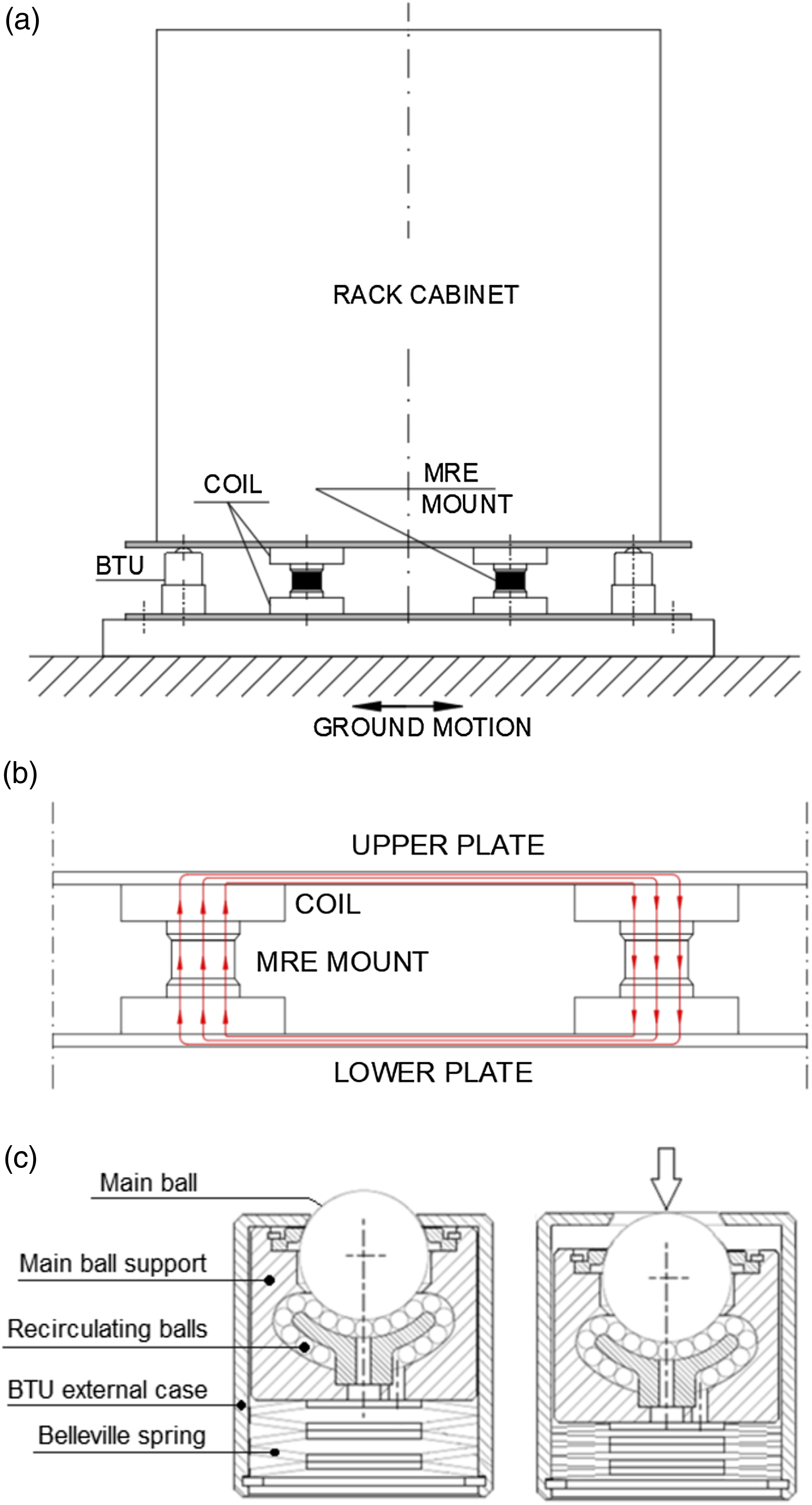
2.1. Isolation device
The MRE device comprises two MRE mounts, each placed between two coils (see Figure 1(a)). Four coils are fed so that the magnetic field, crossing the mounts, closes its circuit in the connecting steel plates (see Figure 1(b)). The re-centring horizontal force exerted by the mounts depends on the magnetic field intensity and, therefore, on the current intensity circulating in the coil windings. To characterize the magnetorheological rubber, some cylindrical pads were realized mixing silicon rubber with 4–6 μm iron–carbonyl particles into a homogeneous mixture. In particular, a silicon elastomeric matrix (Prochima GLS-10), characterized by 10 shore-A hardness, with micro iron–carbonyl particles (4–6 μm) having a volume percentage equal to 25%, was used. The pads were formed in cylindrical mould (diameter: 50 mm; thickness 30 mm); during the curing phase, two permanent magnets were placed over and under the mould to orient the particles according to the magnetic field strength lines to magnify the MRE effect. The magnetic field intensity generated by the magnets was equal to about 190 mT. (Interested readers may refer to Brancati et al. (2018); and Brancati et al. (2019a, 2019b)) for a more detailed experimental investigation of the realized MRE device.) The rolling supports are retractable BTU, Omnitrack 9520, whose main ball diameter is equal to 25.4 mm (see Figure 1(c)); the main ball supports are supported by Belleville springs so that above a load of 1880 N, the main ball retracts into the external case. This peculiarity prevents the isolator from working if the mass to be insulated is excessive, as large inertia forces would damage the MRE mount.
2.2. Experimental setup and tests
To characterize the response of the BTU-MRE–based isolator, several experiments were conducted on two equal cylindrical pads. The pad shear stiffness was experimentally evaluated for different intensities of the magnetic field in the experimental setup, schematically represented in Figure 2. The device under test, constituted by two MRE cylindrical pads connected on the opposite sides of a plastic platelet, was placed on the magnetic core of a coil. The coils consist of an aluminium alloy support and a winding of 1000 turns realized with an AWG 20 insulated copper wire (diameter of 0.821 mm). The wire ends are connected to a direct current power supply for adjusting the current intensity circulating in the winding. The coils are equipped with ferromagnetic cores to increase the magnetic field intensity and to support MRE samples. The coil and sample were pressed by two steel plates connected by four columns; tightening the columns, it is possible to assign an axial preload to the MRE pad. The sample was tested by applying a harmonic shear load by means of a rod driven by an electrodynamic shaker. The shear force exerted by the shaker on the samples was measured by a load cell (Dytran 6210S) placed between the rod and the electrodynamic shaker, whereas the rod displacement was measured by a laser displacement sensor (optoNCDT 1420). These measurement instrumentation were placed as far as possible from the samples to avoid disturbing the magnetic field generated by the coils and the influence of the magnetic field on the measures. For this reason, (a) the load cell was placed between the rod and the shaker. In this way, it measures even rod and platelet inertia forces. As the rod and shaker are made of aluminium alloy and nylon, respectively, they are light enough to consider negligible their inertia forces with respect to the samples’ restoring forces. (b) The displacement laser sensor detects the shaker displacement that can be considered equal to the platelet displacement as the rod deformability is negligible compared with the restoring forces exerted by the MRE samples. Experimental setup.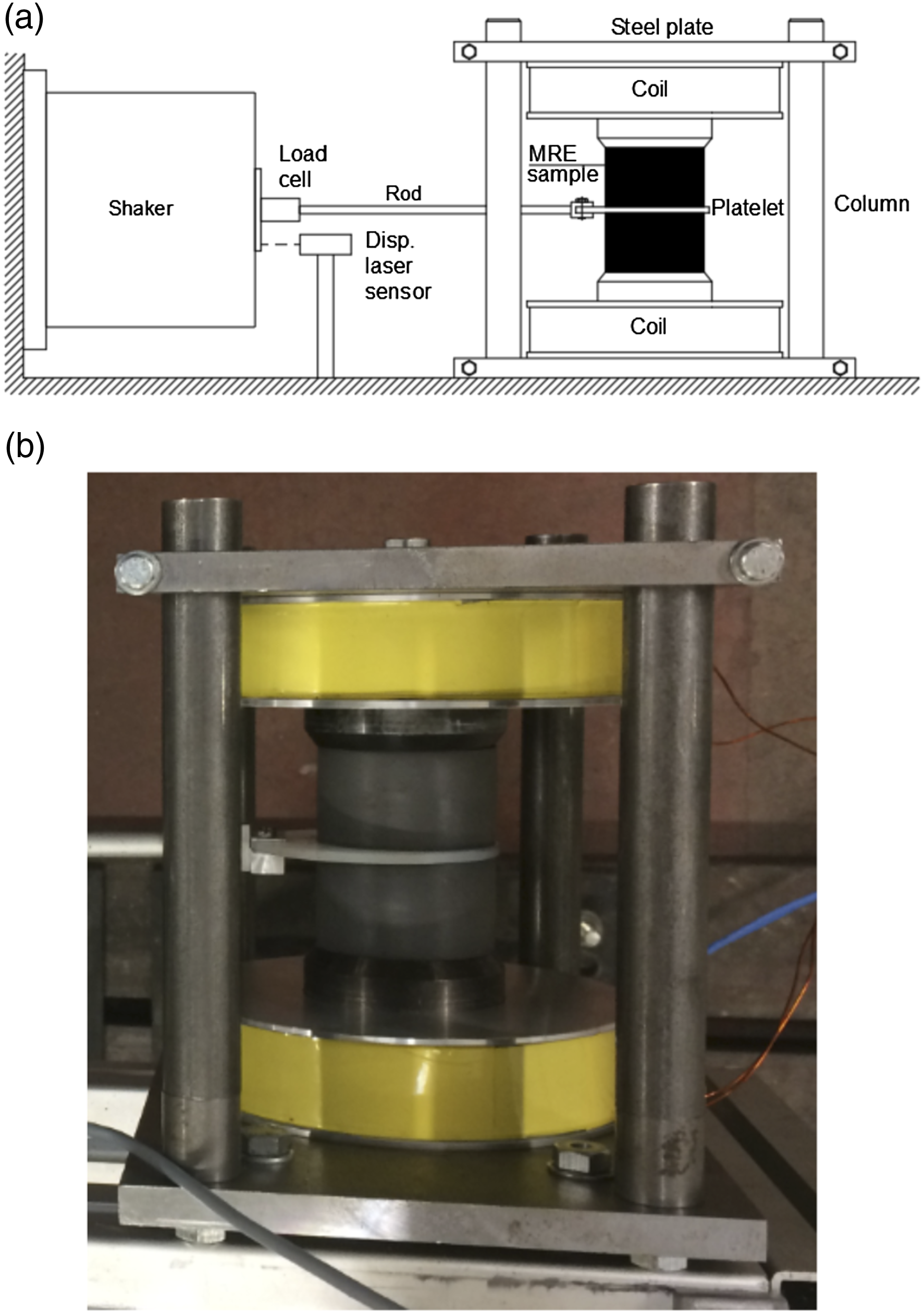
The magnetic field intensity was measured by means of a gaussmeter Brockhaus-BMG101 by placing the probe between the platelet and the sample.
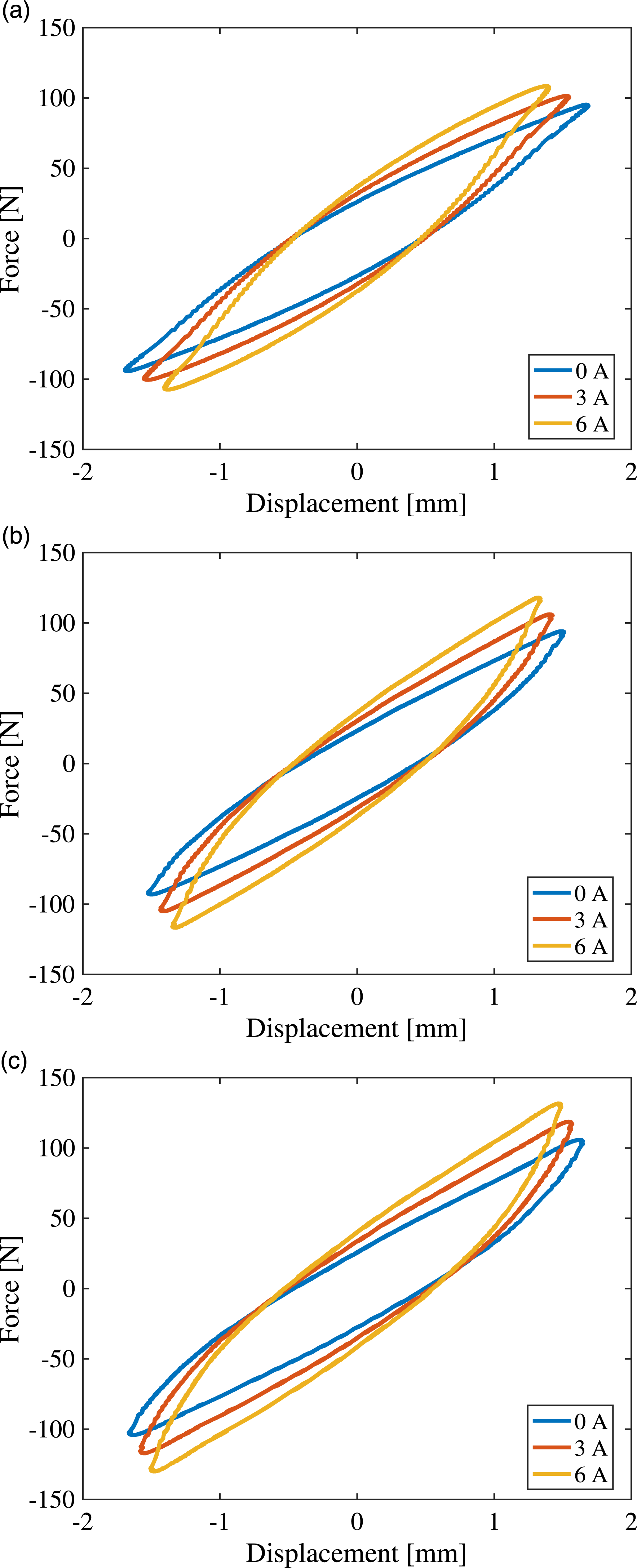
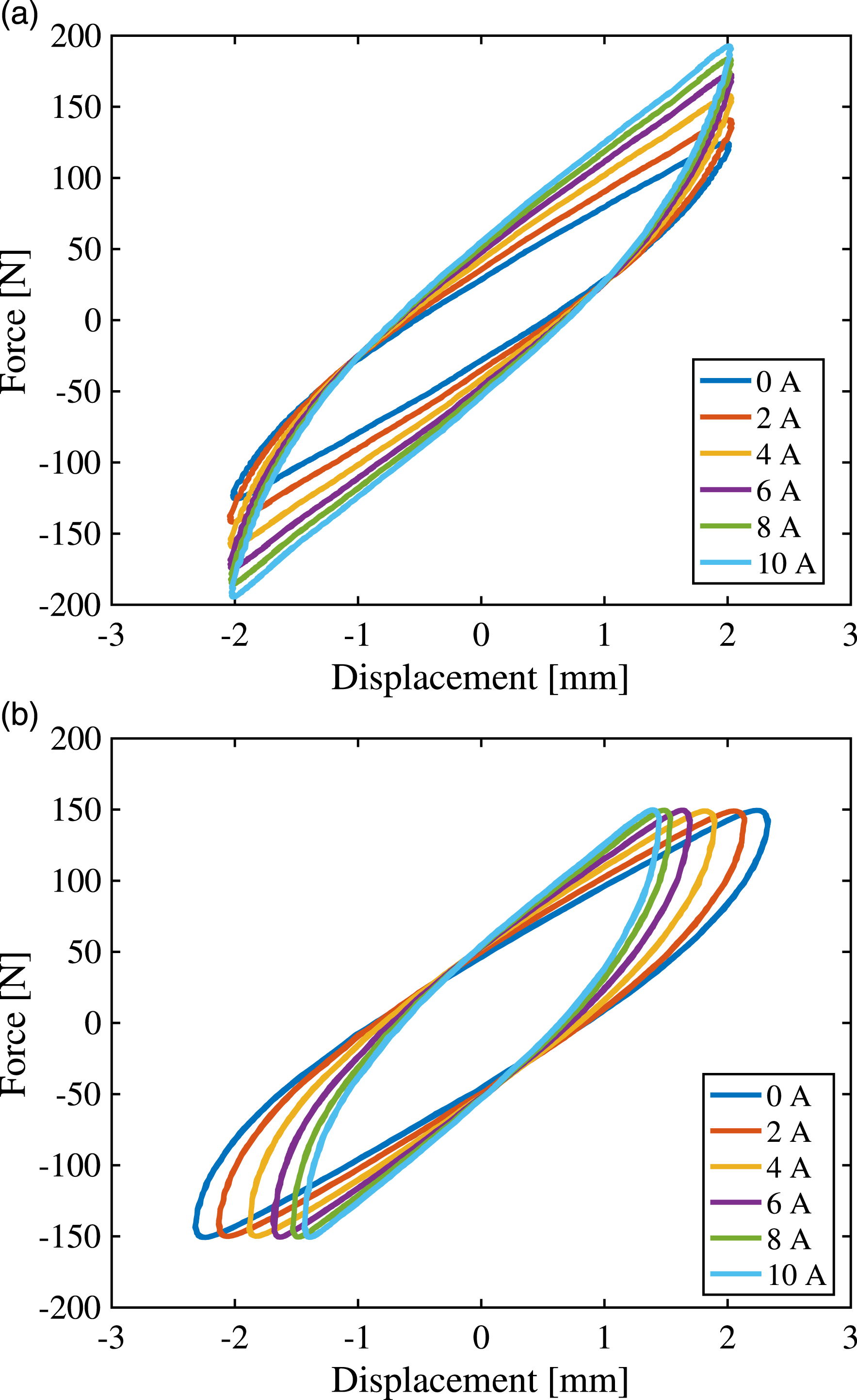
Superimposing a harmonic shear excitation, the following tests were performed: Constant power tests: With a constant power supply of the electrodynamic shaker, the MRE mounts were tested by assigning different frequency excitations and feeding the coils with different current intensities. Figure 3 shows the test results, in terms of force–displacement cycles, performed for 1 Hz, 3 Hz, and 4 Hz frequency excitations at the coil supply intensity currents of 0 A, 3 A, and 6 A. Keeping constant the platelet displacement amplitude tests: Tests were performed for different values of the excitation frequency and of the coil supply current. Figure 4(a) shows the force–displacement cycles obtained for a frequency excitation of 4 Hz and for different values of the coil supply current. Keeping constant the excitation force amplitude: Figure 4(b) shows the test results obtained for Fmax = 300 N, at 10 Hz, for different values of the coil supply current. Force–displacement cycle for constant power excitation: (a) f = 1 Hz; (b) f = 3 Hz; and (c) f = 4 Hz. Characterization of the magnetorheological elastomer pads. Force displacement cycle for (a) a constant motion amplitude of 2 mm and a frequency of 4 Hz and (b) a constant excitation force of 300 N and a frequency of 10 Hz.
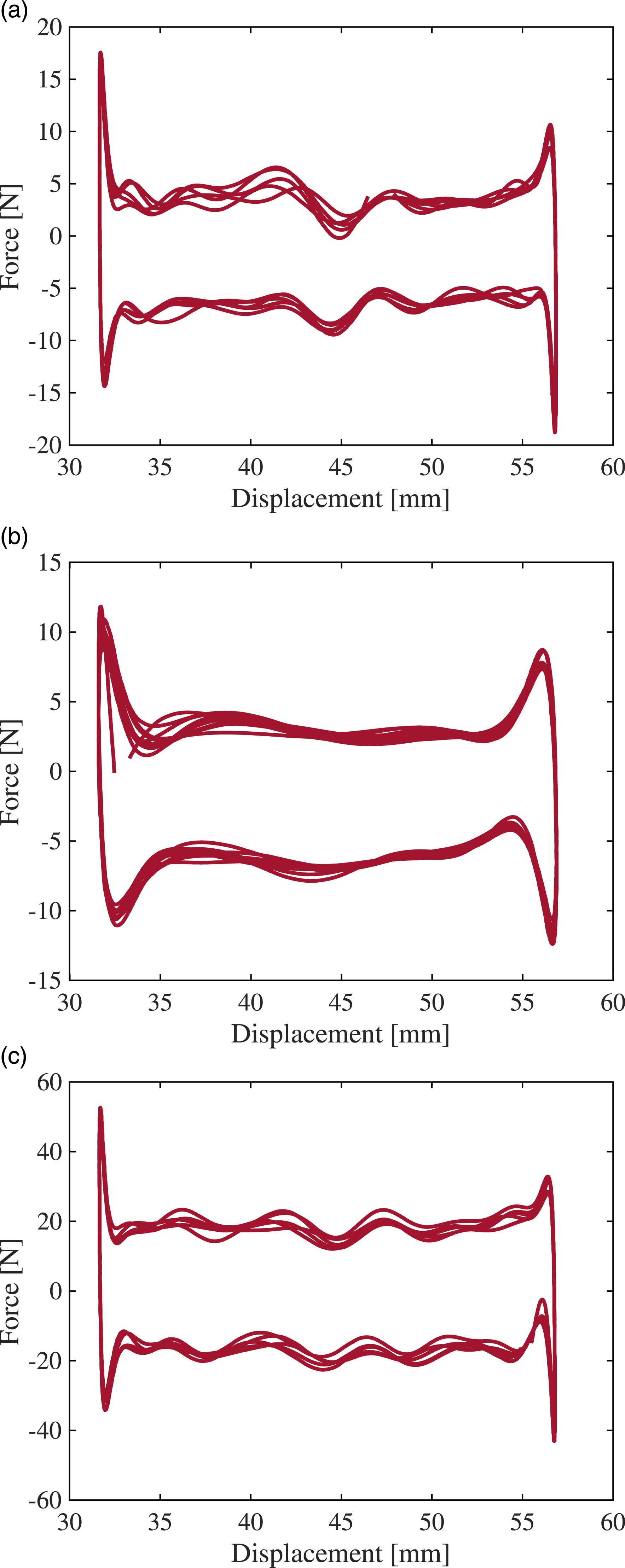
Subsequently, an isolator prototype (Figure 5) was developed. It consists of two steel plates between which there are four BTU supports and two MRE mounts placed between two coils, equal to those used in the previous tests. The device was characterized on a testing machine constituted by a slide driven by a mechanical actuator, based on a slider-crank linkage. By adjusting the crank length and the crank rotation speed, it is possible to assign the slide motion amplitude and its frequency. The ratio between the connecting rod length and that of the crank is, in any case, greater than 5, and therefore, the slide motion can be considered harmonic. The experimental results were obtained for a peak-to-peak slide amplitude of 4.81 mm. To characterize the prototype, the lower plate was fixed on the slide, whereas the upper plate was connected to the testing machine frame by means of a load cell having the sensitive axis parallel to the sliding direction, and by means of two rods equipped with spherical hinges at the ends displaced in perpendicular direction to prevent transverse and yaw plate movements. To detect the BTU support rolling resistance, the tests were initially performed without the MRE mounts, for different values of the ballast mass placed on the upper plate and for different values of the frequency motion. From the test results shown in Figure 6(a)–(c), it can be deduced that the rolling resistance coefficients is equal to about 0.01. It can be noted that the diagram has an almost rectangular shape with a peak corresponding to the motion inversion that can be attributed to the recovery of the backlashes of the mechanical systems; therefore, they are not considered for the rolling resistance estimation. Furthermore, the undulation of the two branches is probably due to imperfect geometry of the rolling surface. Characterization of the isolator prototype. Ball transfer unit rolling resistance characterization. Force–displacement cycle for (a) 60 kg ballast mass at 1 Hz; (b) 60 kg ballast mass at 2 Hz; and (c) 150 kg ballast mass at 1 Hz.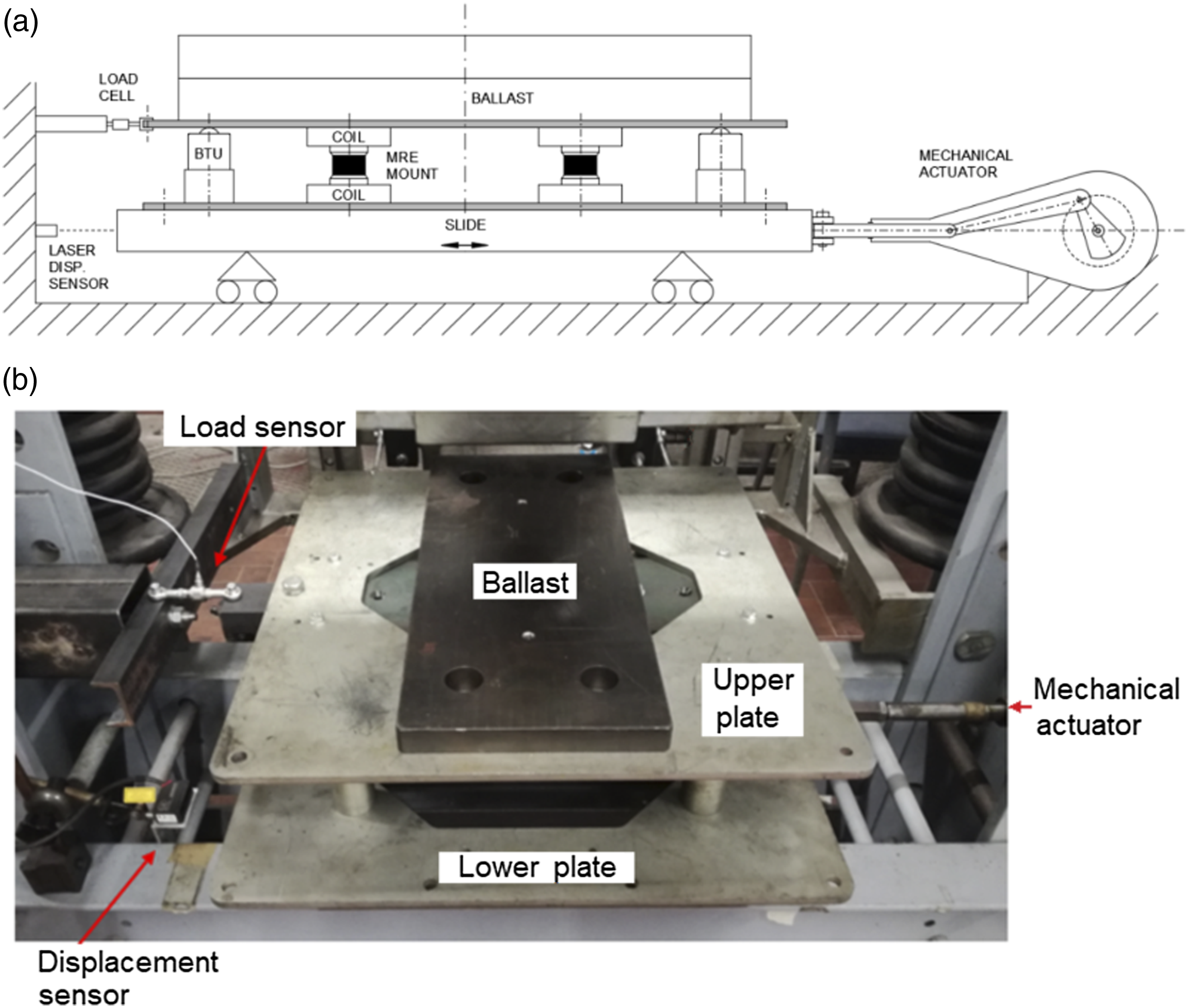
Finally, Figure 7 shows the force–displacement diagram of the prototype in the presence of the BTU support and MRE mounts; the two mounts act in parallel so that the restoring force is quite equal to that obtained with the electrodynamics shaker. As an example, the tests conducted with a ballast mass of 90 kg at a frequency of 0.5 Hz, 1 Hz, and 2 Hz are reported (see Figure 7). These tests were adopted to identify, at the same time, the coefficients of the MRE mount restoring force and the BTU rolling resistance coefficients. Force–displacement cycle for 90 kg ballast mass at (a) f = 0.5 Hz; (b) f = 1 Hz; and (c) f = 2 Hz.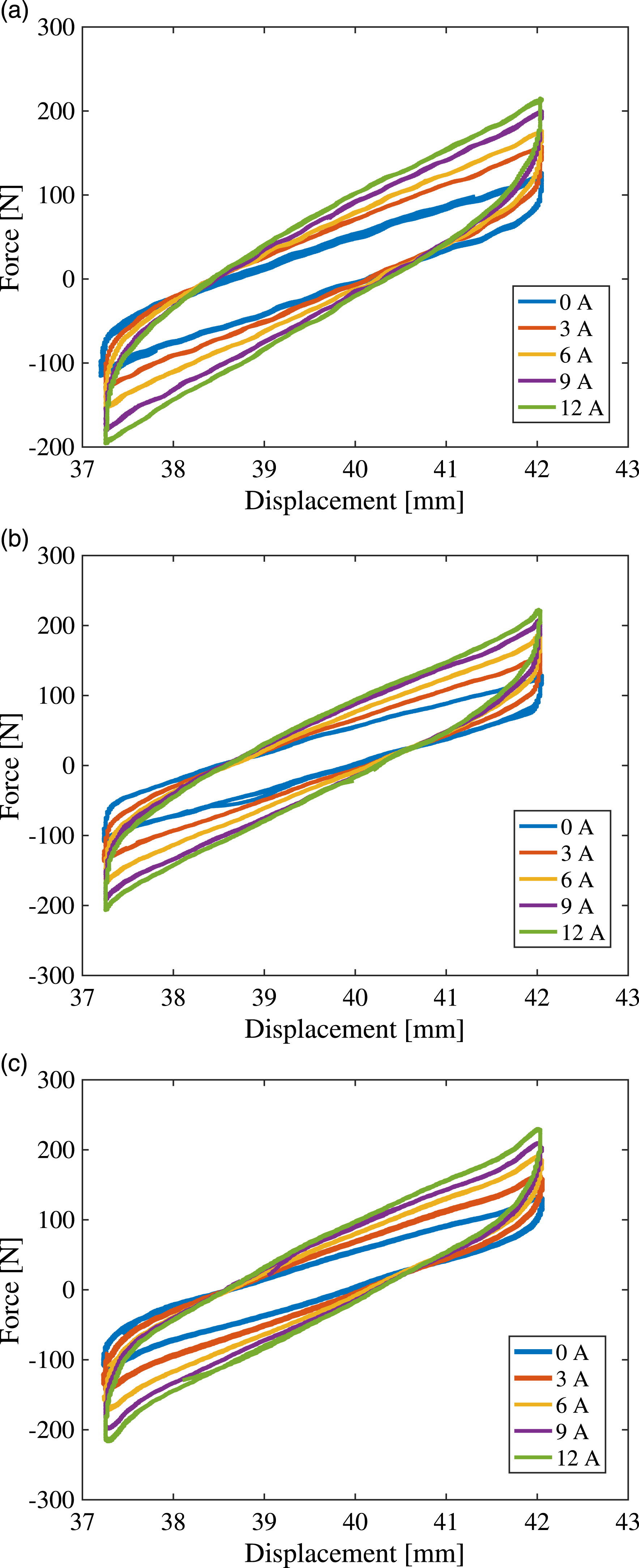
2.3. Dynamical models
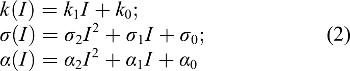
The design and the validation of the active control strategy necessary for properly driving the dynamic response of the closed-loop system are based on a mathematical model that is able to capture the strain stiffening in force–displacement loops and the nonlinear relationship between force and velocity. To this aim, the BTU-MRE–based isolation system is here described by a strain-stiffening model (Yu et al., 2015). It is composed of a spring, a viscous damper, and a strain-stiffening component in a parallel configuration allows for describing the generated shear force FMRE to be imposed on the lightweight structure for the isolation vibration. This model, widely accepted to simply mathematically describe the isolator behaviour, is defined as follows

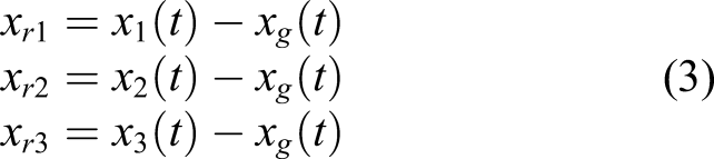
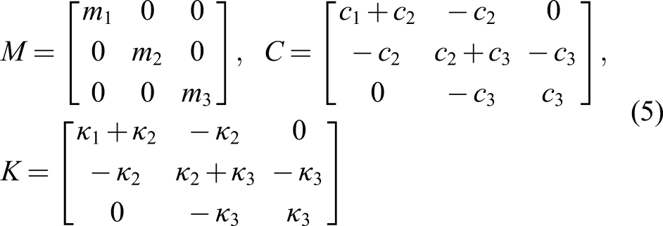
The lightweight structure to be isolated is schematized with a simple mathematical model to evaluate the efficiency of the semi-active insulation system. The cabinet is represented as a three-storey structure with masses m1, m2, and m3 and characterized by the proper stiffness and damping of the beams connecting the masses κ1, κ2, κ3, c1, c2, and c3. We indicate x
g
as the displacement of the ground, and x1(t), x2(t), and x3(t) as the horizontal displacements of the three masses. Note that the BTUs are rolling supports which constrain the structure base from moving, remaining parallel to itself. Defining the displacement of each mass with respect to the ground as

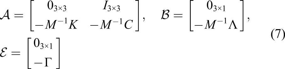
Defining the state vector

3. Model identification for the isolator system
Once a mathematical description suitable for the BTU-MRE–based isolation system is derived, a challenging task is the identification of the values assumed by its parameters, such that the dynamic behaviour of the real plant can be efficiently determined by the simplified model without the necessity of increasing the details and overall complexity of the analytic description.
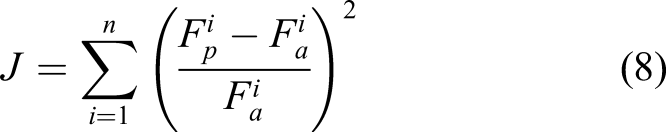
To this aim, the dynamical model of the shear force of the BTU-MRE–based isolator, described by the nonlinear dynamics in (1), has been identified leveraging the results from different experimental tests described in Section 2.2 for different values of current I supplied to the excitation coil. The system identification problem is here formulated as an optimization task, where the objective is to find a set of parameters for the model that minimizes the prediction error between the plant output, that is the measured data, and the model output computed based on a set of known inputs (Vladu and Dragomir, 2005).
More specifically, the exploited identification procedure leverages a hybrid genetic algorithm (HGA) (Persico et al., 2017) to identify the eight parameters (k1, k0, σ2, σ1, σ0, α2, α1, and α0) of the model (1) on the basis of the experimental tests described in Section 2.2. The GAs randomly initialize a population of individuals (parameters belonging to the space of potential solutions) and then let its members evolve towards better regions of the search space by the iterative application of a randomized process of recombination, mutation, and selection. An evaluation function J, related to the objective function to be minimized, determines the quality of each search point at each iteration step. On the basis of the evaluation function, the fittest individuals have a higher probability to become the parent of the new generation of individuals. The HGA exploits further enhancement of the GA with a nonlinear least-square (LS) method to merge the global search properties of GAs with the fast local convergence of LS methods. The identification procedure uses the following evaluation function
The overall parameter identification results are as follows: k1 N/mm = 6.44 k0 N/mm = 46.82 σ2 Ns/mm = −0.41 σ1 Ns/mm = 14 σ0 Ns/mm = 100.4 α2 N/mm3 = −0.12 α1 N/mm3 = −0.09 α0 N/mm3 = 1.80
As an example of the identification effectiveness, Figure 8(a) shows the tracking performance and relative errors of the predicted and measured force with increasing time for 4 Hz—frequency and 0 A current. Note that the relative error between the measured force and the predicted one is at most equal to 6%, that is 15 N (see Figure 8(b)). Identification of parameter performance (f = 4 Hz – I = 0 A). (a) BTU-magnetorheological elastomers–based forces with respect to time. (b) Relative error with respect to time.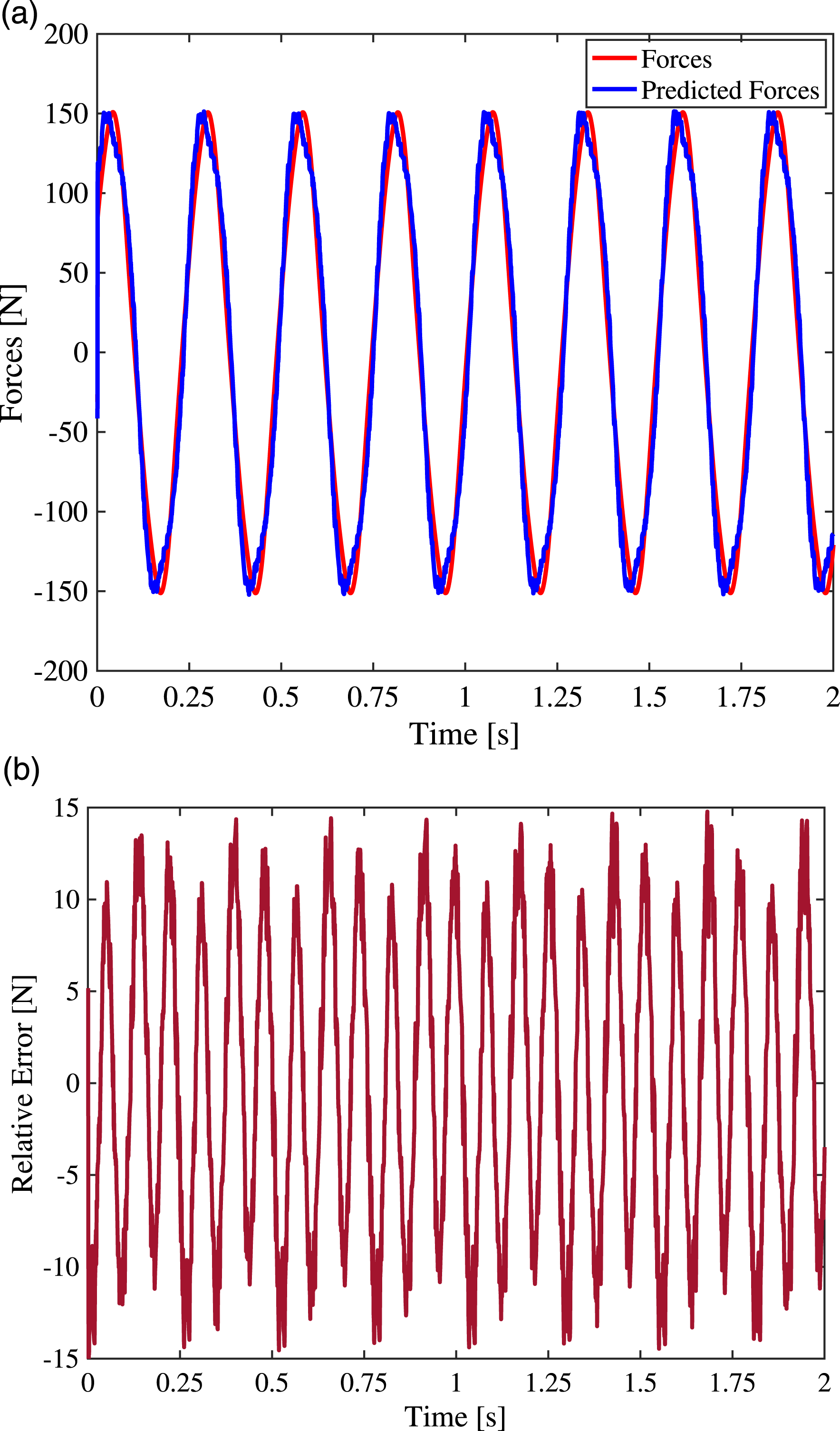
4. Control design
The BTU-MRE–based isolation system allows for combining the reliability of passive isolators with the adaptation capability of the active isolators on the basis of its actual condition. Indeed, opportunely controlling the current supplied to the magnetic coil allows for real-time modification of the isolator physical characteristics, such as stiffness and damping.
Hence, our aim was to design a control system allowing for the determination of the magnetization current so as to (1) minimize the relative displacement and relative velocity of each floor of the lightweight structure, that is optimizing the differences x ri (t) − x rj (t) and ẋ ri (t) −ẋ rj (t) ∀i, j = 1, 2, 3 with i ≠ j, and (2) reduce the acceleration peaks transmitted by the earthquake to each floor of the structure. To meet both the control objectives, the control system design for the isolated lightweight structure requires the following two stage actions to generate the proper magnetization current: (i) determining the desired primary control action, that is the actuation force that needs to be imposed on the structure, so as to reduce the vibration transmitted to the structure and (ii) determining the required control input, that is the magnetization current, to drive the BTU-MRE–based isolation system to generate the desired control action.
Leveraging the state feedback information of the isolated lightweight structure, that is x ri ẋ ri (i = 1, 2, 3), the desired primary control action is designed according to a MPC approach (Allgöwer and Zheng, 2012; Amodeo et al., 2018). To determine, instead, the required magnetization current, we use a regression neural network (RNN) inverse model of the BTU-MRE–based isolation system allowing for the derivation of the control command from the desired control force computed by the MPC controller.
A schematic overview of the designed control architecture can be found in Figure 9. Schematic overview of the control approach.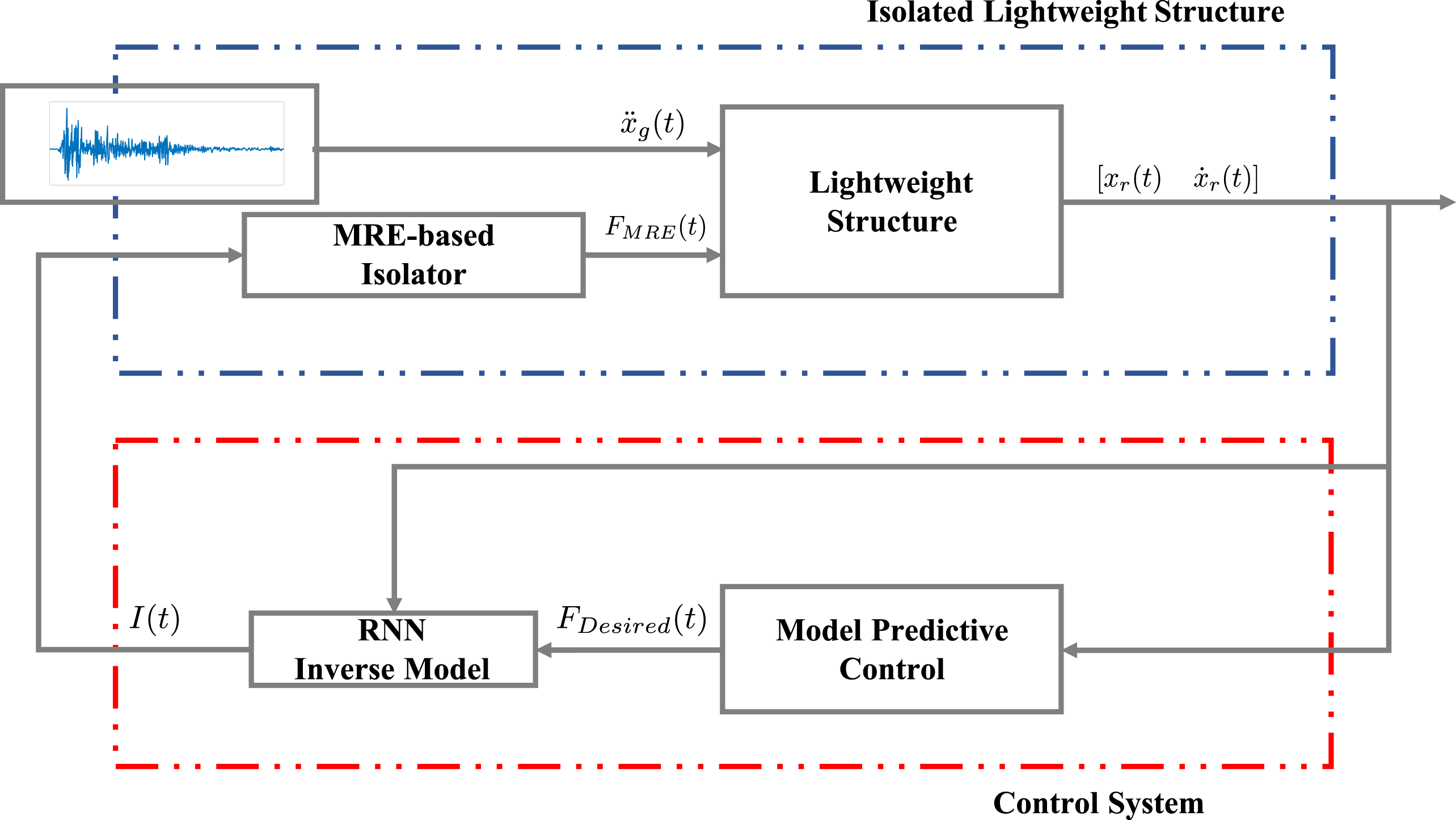
4.1. Primary control action: model-predictive control
The MPC is an advanced method to control a process while satisfying a set of constraints. This method relies on a dynamic model of the process which allows for anticipating future events and acts accordingly. The control commands are computed by solving an optimization problem on a finite time horizon T, but acting the computed control input at the current time slot T c and then optimizing again, repeatedly. Therefore, the control approach allows for coping with the uncertainty of the dynamical system under investigation (e.g. the inaccurate knowledge of the ground vibration frequency).
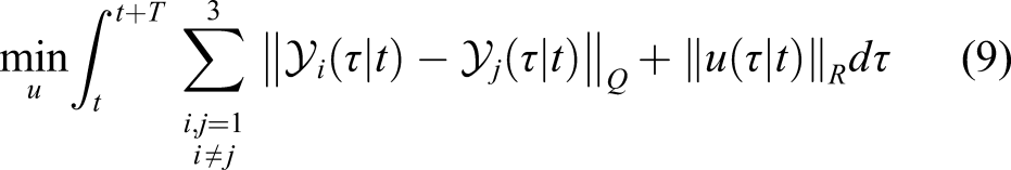
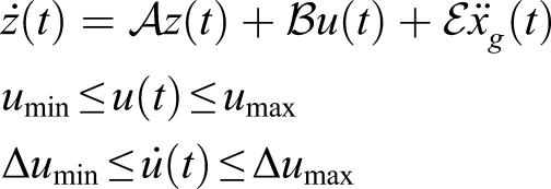
The desired control force u(t) in equation (6), allowing for reducing the vibration transmitted to the structure by the earthquake, is hence computed as the solution of the following optimization control problem to be solved repeatedly online for a receding horizon of finite length T
4.2. Regression neural network inverse model of MRE-based isolator
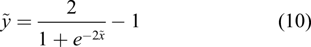
To depict the nonlinear relationship between BTU-MRE–based isolator response and the applied current intensity, a RNN inverse model is developed. This model, realized by using the data set obtained from the experimental campaign presented in Section 2.2, is characterized by a multilayer perceptron consisting of an input layer, a hidden layer with 50 neurons, and an output layer as shown in Figure 10. The input variables of our model are the displacement of the first floor with respect to the ground at time t and t − 1, its relative velocity at time t, and the desired shear force at time t. The output of the model is the desired applied magnetization current at time t. The input layer, consisting of four neurons (as the number of the inverse model input), aims at transmitting these inputs to the hidden layer. In the latter, each neuron uses a tan-sigmoid activation function, expressed as Configuration of regression neural network–based inverse model for magnetorheological elastomer–based isolators.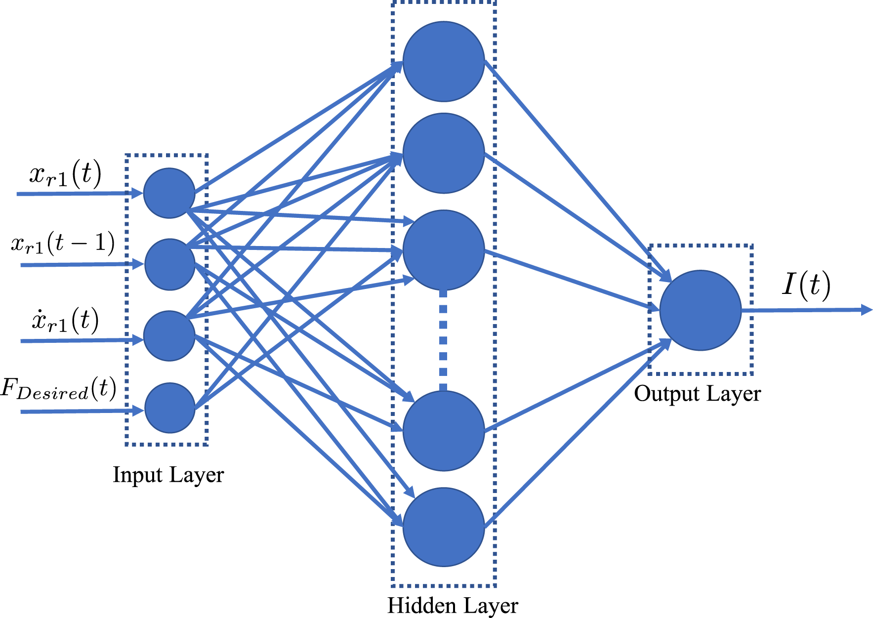
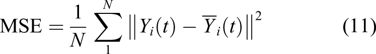
Among the 73,600 available sets of data (obtained through the procedure detailed in Section 2.2), the first 66,060 are exploited for training the RNN and the last 7,540 sets are used as validation data. The training process has been implemented via the Levenberg–Marquardt back-propagation algorithm, which uses the following performance function Performance evaluation of the RNN inverse model: (a) comparison between the measured current and the predicted current made by the RNN inverse model; (b) analysis of the regression correlation coefficient R2. RNN: regression neural network.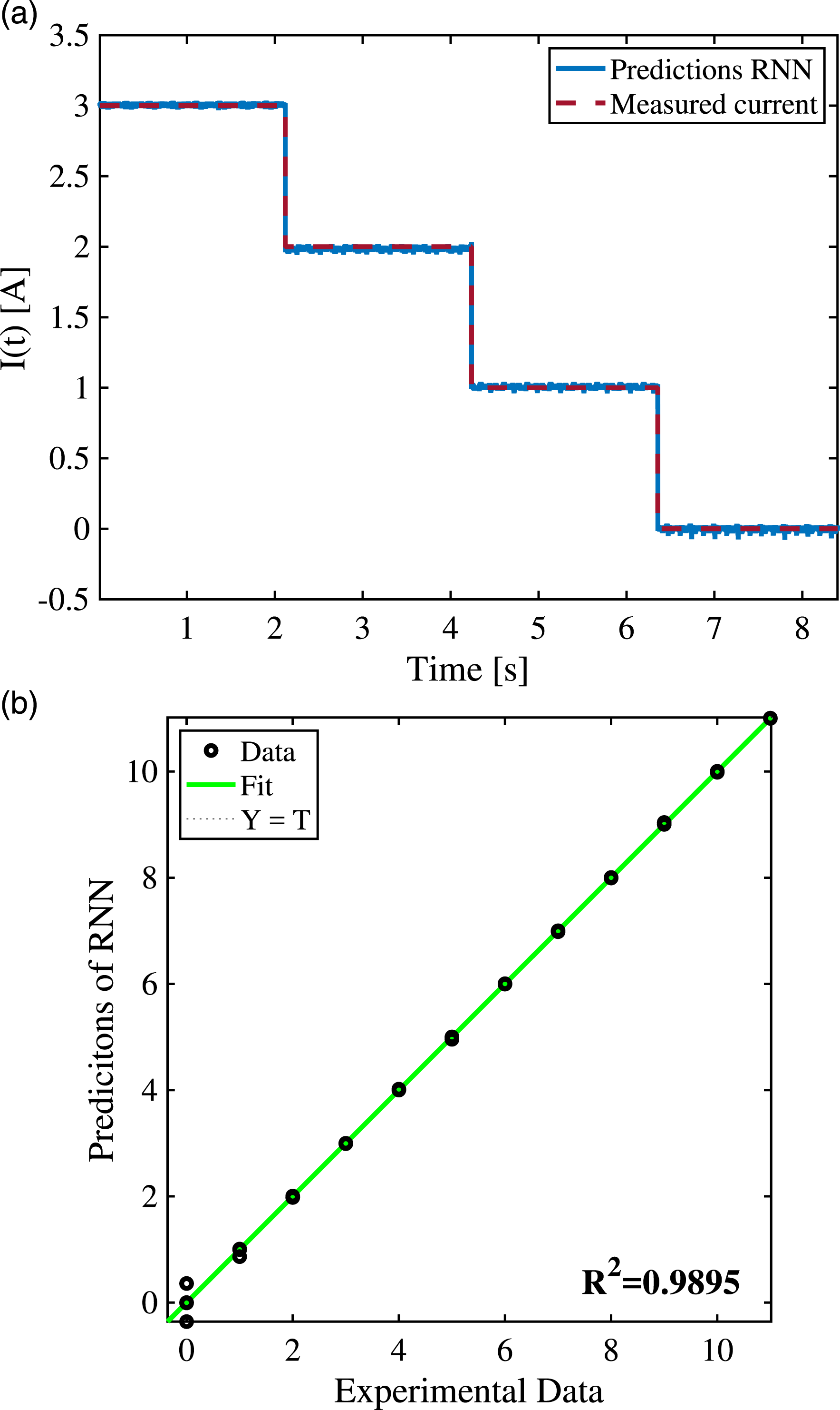
5. Numerical results
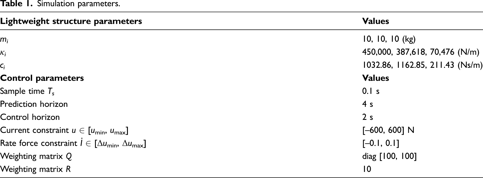
Simulation parameters.
Results refer to two isolation scenarios under the appraised earthquake. Specifically, it will be compared with the dynamical response in case of (a) a fixed-base structure that is resting on the ground without any isolation device and (b) the structure that is isolated through the herein proposed control strategy.
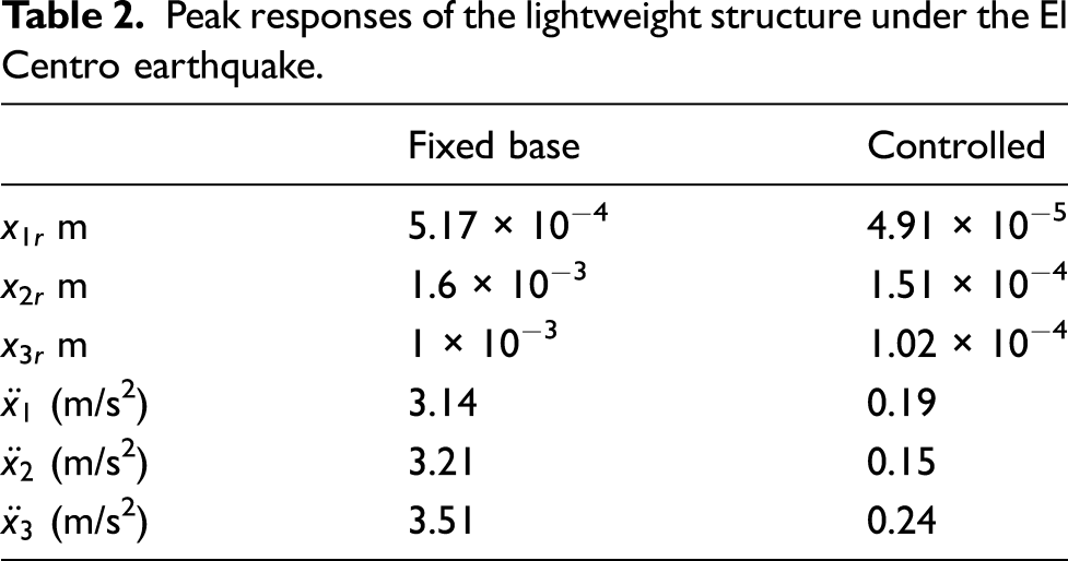
Numerical results, depicted in Figure 12, disclose the performance of the proposed control approach in guaranteeing the vibration isolation of the lightweight structure. Specifically, Figure 12(a)–(c) show the absolute acceleration responses of the isolated lightweight structure compared with respect to the fixed-base case. As it is possible to observe, the proposed control strategy is able to increase the isolation performances of each floor of the structure by effectively reducing the structural responses to the earthquake to about 80%. Accordingly, the relative displacement of each floor with respect to the ground, that is x
ri
(t) (i = 1, 2, 3), shown in Figure 12(d)–(f), and the relative displacement of each floor, shown in Figure 12(g)–(i), are considerably reduced to one order of magnitude, if compared with the fixed-base scenario. Moreover, vibration isolation performances are further confirmed by the acceleration transmissibility diagrams of each floor depicted in Figure 12(j)–(l) that are obtained as the ratio of the fast Fourier transformation (FFT) of specific floor acceleration to the FFT of the ground acceleration. The good performances achieved can be also appreciated by observing Table 2, where the peak responses of the lightweight structure under the El Centro earthquake are compared with both the appraised isolation cases. Dynamical responses of the isolated lightweight structure under an El Centro earthquake. (a) Time history of the first floor absolute acceleration, i.e. ẍ1(t); (b) time history of the second floor absolute acceleration, i.e. ẍ2(t); (c) time history of the third floor absolute acceleration, i.e. ẍ3(t); (d) time history of the first floor displacement x1r(t); (e) time history of the second floor displacement x2r(t); (f) time history of the third floor displacement x3r(t); (g) time history of the relative displacement of the third floor to the first floor, that is x3r(t) − x1r(t); (h) time history of the relative displacement of the third floor to the second floor, that is x3r(t) − x2r(t); (i) time history of the relative displacement of the second floor to the first floor, that is x2r(t) − x1r(t); (j) acceleration transmissibility diagram of the first floor under the action of the proposed control strategy; (k) acceleration transmissibility diagram of the second floor under the action of the proposed control strategy; and (l) acceleration transmissibility diagram of the third floor under the action of the proposed control strategy. Peak responses of the lightweight structure under the El Centro earthquake.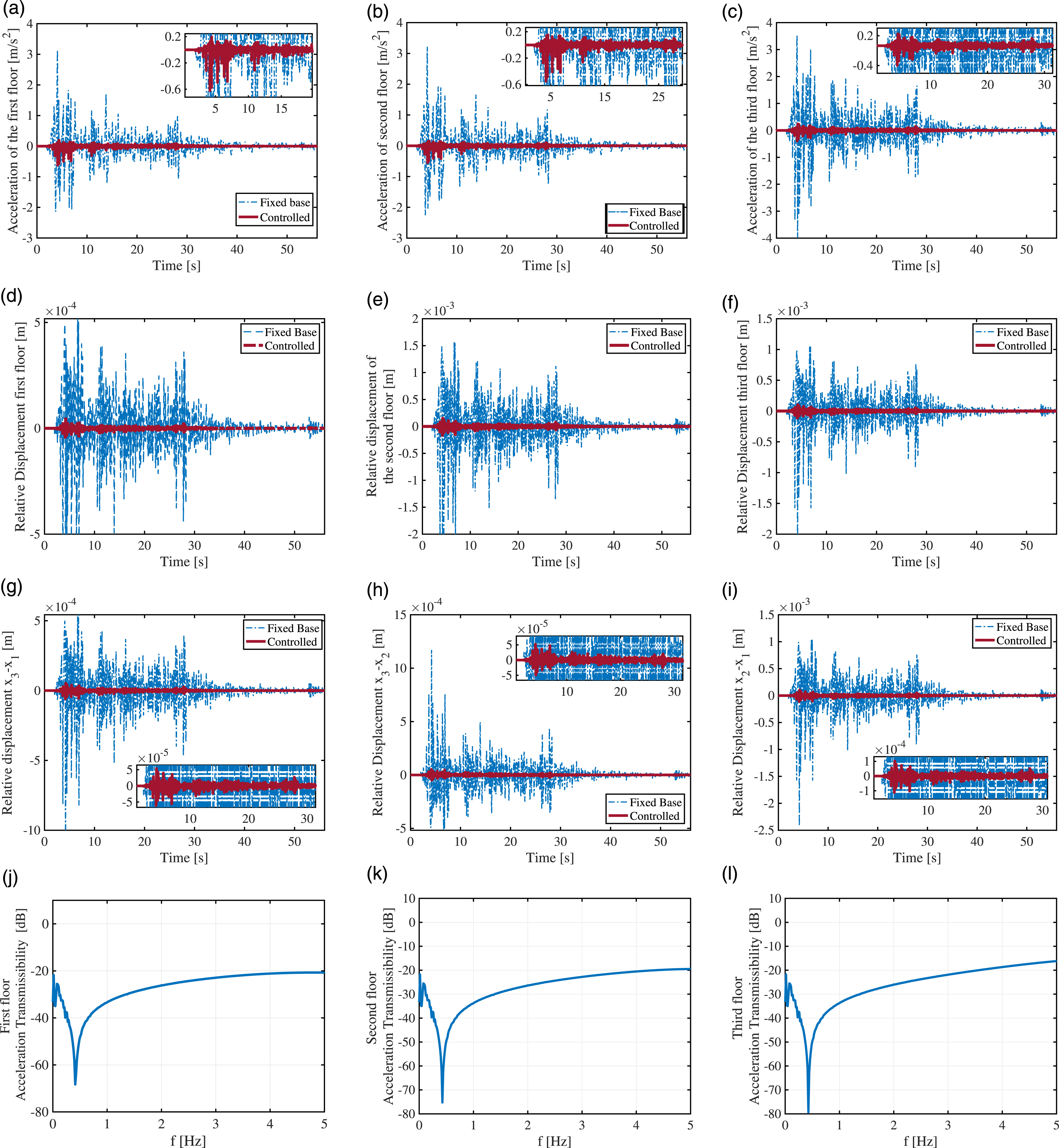
To further disclose the efficiency of the proposed control strategy, we compare the desired primary control action, computed by the MPC controller, that is FDesired(t), with the force effectively generated by the BTU-MRE–based isolation system, that is FMRE(t), on the basis of the magnetization current I(t) predicted by the RNN inverse model. The latter, computed on the basis of the desired primary control action determined by the MPC controller, is reported in Figure 13(a). On the basis of this magnetization current, the BTU-MRE–based isolation system computes the force FMRE to be imposed on the lightweight structure. Figure 13(b) shows that the force generated by the BTU-MRE–based isolation system effectively tracks, with small bounded error (see Figure 13(c)), the desired force computed by the MPC controller, hence pointing out the effectiveness of the RNN inverse model in predicting the proper current to drive the isolation system to obtain lightweight structure vibration isolation. Control input. (a) Applied electric current in the ball transfer unit–magnetorheological elastomer (BTU-MRE)–based isolator; (b) comparison between the desired force computed by MPC and the actual force generated by the BTU-MRE–based isolator on the basis of the regression neural network prediction; and (c) error force computed as FDesired(t) − FMRE(t).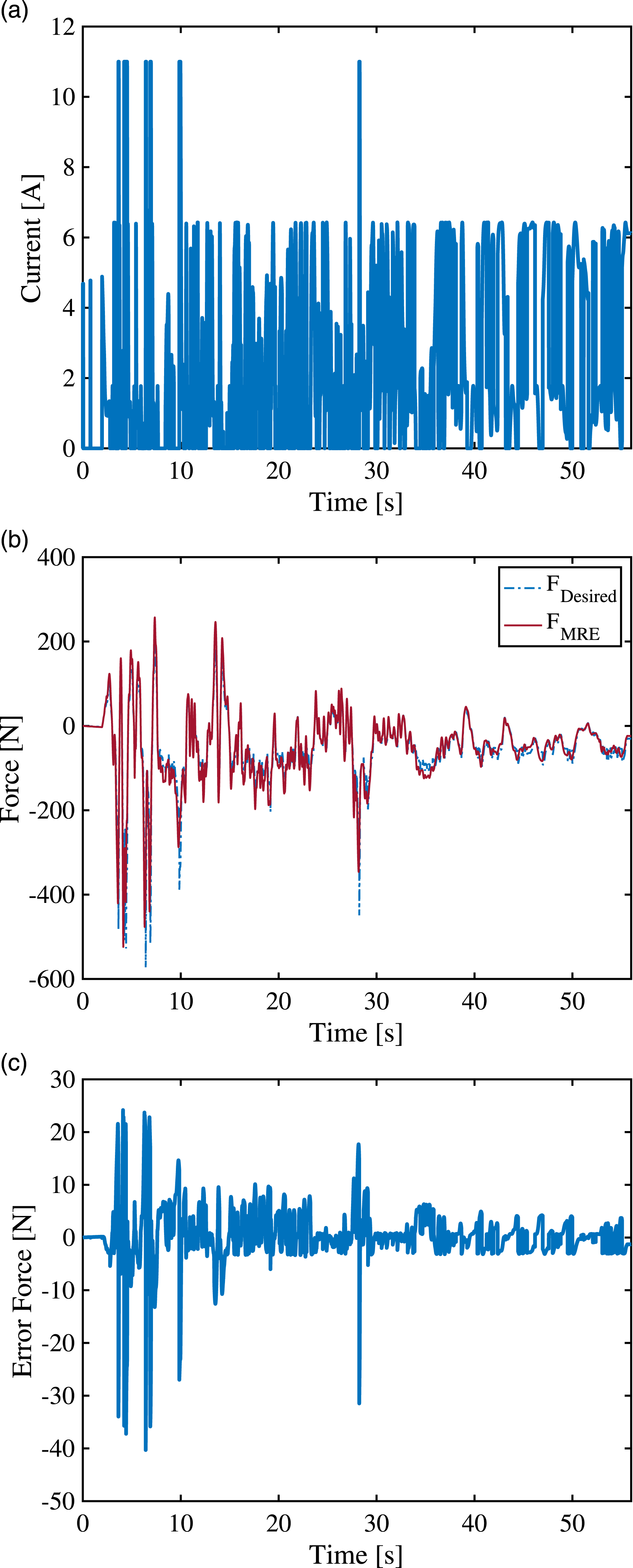
6. Conclusion
This study has addressed and solved the problem of vibration isolation of lightweight structures by presenting a novel BTU-MRE–based isolator prototype and by proposing a novel combined NN and MPC approach allowing for its proper functioning. The effectiveness of the proposed semi-active insulation system in guaranteeing vibration isolation has been proven by considering a rack-cabinet composed of three storeys and subject to an El Centro earthquake. Numerical simulations have confirmed the validity of the approach and have disclosed a good vibration reduction of the lightweight structure subject to evaluated earthquake. Our future experimental validation will regard to a cabinet equipped with this isolation device, excited by means of a shaking table. We will experimentally investigate the actual acceleration transmissibility levels and then, by separately controlling the two MRE pads of the device, we will try to simultaneously optimize the translation and rotation (yaw) motion of the cabinet.
Footnotes
Acknowledgements
The authors would like to thank Luca Ioviero for his valuable contribution to this work.
Declaration of conflicting interests
The author(s) declared no potential conflicts of interest with respect to the research, authorship, and/or publication of this article.
Funding
The author(s) disclosed receipt of the following financial support for the research, authorship, and/or publication of this article: This research was supported by University of Naples Federico II under the project D.R. N. 408 (000010–ALTRI-2017-S-SANTINI_001_001).