





Abstract
In this article, adaptive backstepping sliding mode controller and adaptive fractional backstepping sliding mode controller methods are proposed to control an electrostatic microplate with a piezoelectric layer. Based on the modified couple stress theory, a size-dependent mathematical model is proposed, in which the microplate is modeled using the Kirchhoff plate theory. To take into account the geometric nonlinearities, the von Kármán nonlinear strains are considered in the mathematical model. The Hamilton’s principle is used to obtain the nonlinear equation of motion of the system, which is then converted into a nonlinear ordinary differential equation via the Galerkin technique. The validity of the results obtained from the proposed reduced-order model is checked through direct numerical simulation of the partial differential equation using the finite element method. Finally, two Lyapunov-based control approaches that are adaptive backstepping sliding mode and adaptive fractional backstepping sliding mode are applied to the system. In the adaptive fractional backstepping sliding mode controller method, the adaptive control law is used to evaluate the upper bound of uncertainties and random disturbances. The fractional-order form of sliding surface is used to reduce the amount of chattering and also to improve the tracking error. In the results section, first, numerical studies are conducted to study the effect of system parameters, such as material length scale parameter, aspect ratio, fractional order, and robustness of the controller, on the performance of the system. In addition, the performances of the two control methods are compared, and the merits and demerits of each method are discussed.
Keywords
1. Introduction
Microelectromechanical systems (MEMSs) have a wide range of applications in various engineering fields. Nonlinearities have an important role in MEMS dynamics. For the electrostatic MEMS, the nonlinearity is due to the nonlinear relation between the displacement of the moveable electrode and the electrostatic force. Conducted experiments revealed that the behavior of systems on a small scale is size dependent (Fleck et al., 1994; McFarland and Colton, 2005). Reasons for the change in the behavior of small-size structures are crystallographic texture, grain morphology, surface morphology, self-diffusion, secondary grain growth, defect structure, and interdiffusion (Miller et al., 2007). Researchers have experimentally studied the size effect (Chasiotis and Knauss, 2002; Greer and Nix, 2008; Miller et al., 2007). Lam et al. (2004) indicated that when the size of the structure is more than four times the higher order length scale parameters, the size effect can be ignored.
Because of the importance of the size effect, researchers have tried to propose models that are able to capture the size effect (Lam et al., 2003; Yang et al., 2002). The modified couple stress theory (MCST) (Yang et al., 2002) has the benefit of being able to capture the size effect by introducing only one additional parameter: material length scale parameter (MLSP). The simplicity of the model along with its high accuracy encouraged researchers to use MCST to study the size-dependent behavior of structures (Kazemi et al., 2019; Kim and Reddy, 2013; Kim et al., 2019; Wi and Sodemann, 2019). In recent years, other size-dependent theories have also been used by researchers to study the mechanical response of MEMS and nano–electro–mechanical systems (NEMS) (Karimipour et al., 2019; Kim and Reddy, 2017; Żur et al., 2020). However, most of these studies have focused on the static and dynamic response of such systems, and less attention has been paid to the role of size effect on the control of MEMS and NEMS.
In recent years, MEMSs have shown to have vast applications in different microdevices, such as adaptive focus lens, MEMS loudspeakers, micropump, pressure sensors, and temperature sensors. Because of the increasing demand for such microdevices, researchers have concentrated on increasing the sensitivity of these systems. Based on the conducted research works, nonlinearities play an important role in the failure of dynamic systems (Alsaleem and Younis, 2010). Hence, studying the control behaviors and enhancing the efficiency, accuracy, and stability of electrostatic MEMS have been a matter of interest of many researchers (Gu and Zhu, 2014; Radgolchin and Moeenfard, 2018). Several control methods such as sliding mode control (SMC) (Dastaviz and Binazadeh, 2019; Vahidi-Moghaddam et al., 2018), fuzzy control (Tooranjipour et al., 2019; Zou et al., 2019), and backstepping control (Meng et al., 2019) have been vastly used to control the nonlinear mechanical systems. These methods have been shown to be able to encounter uncertainties and disturbances. However, there are problems with these methods when used alone (Li and Wang, 2018). Another controller that has been used by researchers is the delayed feedback controller. The output signal of this controller is a delayed value of the system output. Displacement, velocity, and acceleration can be the delayed feedback signal (Shao et al., 2013). Conducted research reveals that a careful selection of the delayed feedback controller can effectively improve the control performance of systems (Alsaleem and Younis, 2010; Han et al., 2018). Nwagoum Tuwa and Woafo (2018a) studied an electrostatically actuated microplate subjected to proportional–derivative controllers. They showed that the increase of delay and the sampling time reduces the stability domain. Ngouabo et al. (2020) performed a nonlinear analysis to study electrostatic MEMS resonators subjected to delayed proportional–derivative controller. They showed that changing the proportional gain and derivative gain influences the region of regular motion.
To enhance the tracking performance for nonlinear systems, researchers have used different combinations of control algorithms. The flexibility of the backstepping method makes it an appropriate choice to solve different design issues under more extensive conditions. Moreover, as this method is a systematic design technique, better stability analysis can be provided for backstepping-based control algorithms. In addition, lower computational cost along with the ability to improve the system robustness is some of the reasons for the superiority of the backstepping method over other control methods such as fuzzy method. Nwagoum Tuwa and Woafo (2018b) used an adaptive backstepping sliding mode controller (ABSMC) approach to study the performance of an electrostatic microplate with a piezoelectric layer. Truong et al. (2019) presented an adaptive fuzzy backstepping sliding method for controlling a 3-degrees of freedom hydraulic manipulator. Moezi et al. (2019) proposed a combination of fuzzy control and fractional-order backstepping SMC to study the nonlinear behavior of systems.
As stated earlier, control methods, such as SMC, backstepping control, and fuzzy control, have been vastly used by researchers, although there are problems such as chattering, low control accuracy, and high heat losses in electrical power circuits which need to be answered. In this regard, searching for practical combinations of control methods seems necessary.
The aforementioned valuable studies mainly ignored the size effect, while studying the stability behavior of MEMS; in addition, the literature is limited on comparing the capabilities of the ABSMC and adaptive fractional backstepping sliding mode controller (AFBSMC). Therefore, in this article, the MCST along with the combination ABSMC and AFBSMC approaches is used to control an electrically actuated rectangular microplate with a piezoelectric layer.
For this purpose, in Section 2, a modified couple stress–based model is presented, and the nonlinear equation of motion of the system is obtained. In Section 3, the reduced-order form of the equation of motion of the system is obtained by using the Galerkin decomposition method. In Section 4, two Lyapunov-based control approaches are applied to the system, and the stability of the closed-loop system is investigated. Finally, in Section 5, the results of simulations are presented.
2. Modified couples stress–based microplate model
A schematic of the considered model is depicted in Figure 1. The moveable part is a plate with length A schematic representation of a microplate with a piezoelectric layer.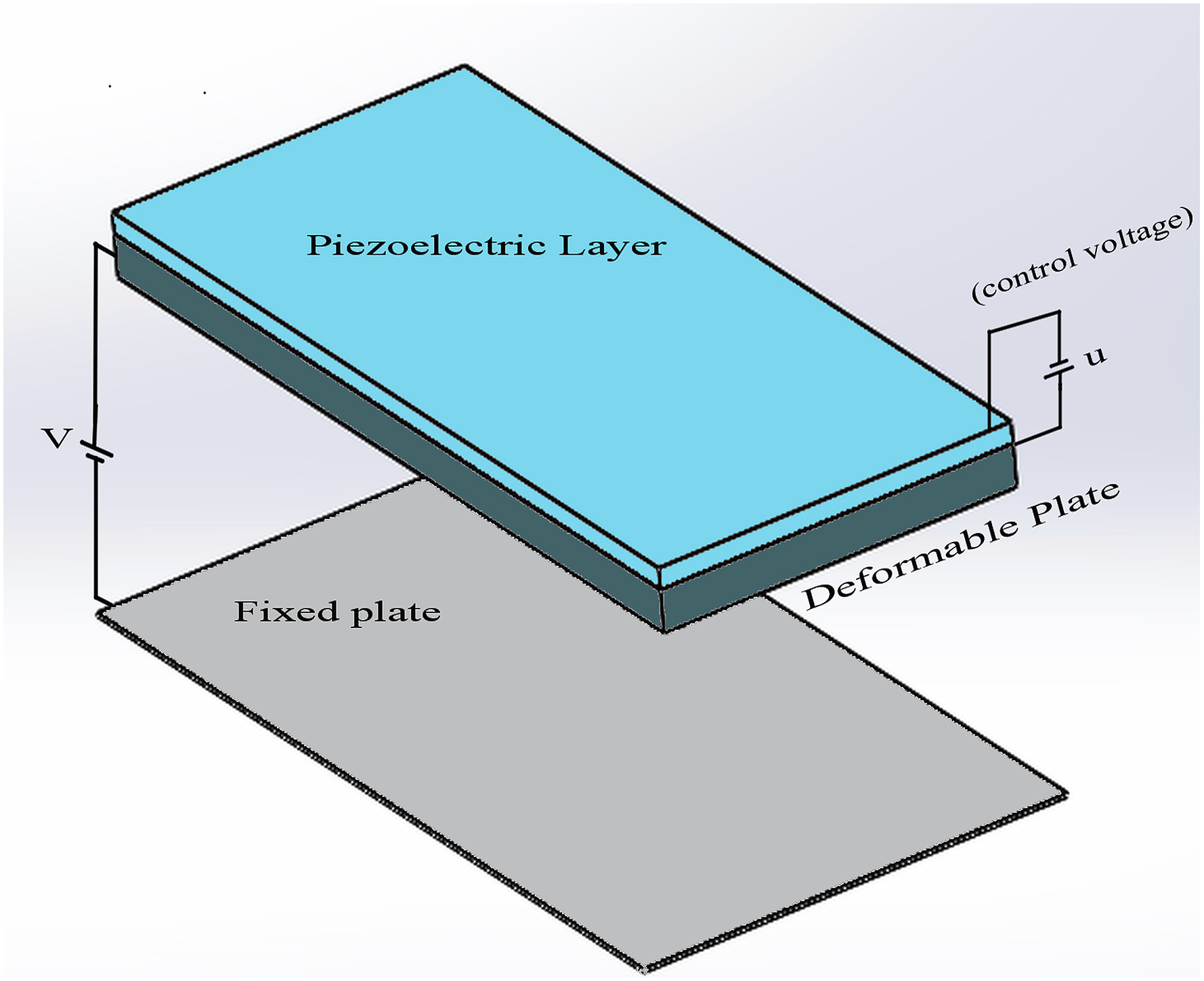
2.1. External forces
Simplicity and high efficiency have made electrostatic actuation the most well-established actuation method for MEMS devices. In addition, by applying a bounded noise to the formulation, small fluctuations and parametric uncertainties can also be encountered. In this regard, an electrostatic force and a bounded noise are considered as external forces in this study.
2.1.1. Electrostatic force
By applying a direct current voltage between the fixed electrode and the moveable part, an electrostatic force is created in MEMS which can be written as (Nwagoum Tuwa and Woafo, 2018b)

2.1.2. Bounded noise
The realistic model of stochastic fluctuations in engineering applications models the excitation as a bounded noise (Deng et al., 2014; Nwagoum Tuwa and Woafo, 2018b). In this article, to consider the parametric uncertainties and small fluctuations between the two electrodes, it is assumed that a bounded noise is applied to the system, which can be expressed as (Nwagoum Tuwa and Woafo, 2018b)

2.2. Equation of motion
The microplate is modeled using the Kirchhoff plate theory along with von Kármán nonlinear strains. Hamilton’s principle is used to obtain the equation of motion of the system. The principle can be stated as


By substituting


The thickness of the piezoelectric layer is small enough that we can assume the electric field to be constant in this layer. The electric field can be written as

The hysteresis nonlinearity is decomposed into two different terms as follows (Gu and Zhu, 2014; Liaw et al., 2007a, 2007b)

In equation (8),

The boundary conditions applied to the system are presented in equation (10)

3. Modal equation and numerical scheme
To solve the partial differential equation of motion equation (9), the Galerkin decomposition method is used to convert this equation to an ordinary differential equation. For this purpose, in equation (9), the transverse deflection of the plate is expressed as


Because of the complexity of analytical integration of the electrostatic force, this force is approximated by the Taylor expansion series

Only the first four terms are considered because adding more terms does not have a prominent effect on the result. Substituting equation (13) into (9) and by using the nondimensional variables introduced in equation (12), one obtains

Material and geometrical properties of the plate and piezoelectric layer.

3.1. Finite element model
To ensure the accuracy of the results from the reduced-order model in equation (14), in this section, the finite element method (FEM) is used to directly solve the nonlinear partial differential equation of motion equation (9). First, appropriate weight functions 

Based on the weak form presented in equation (15), the transverse deflection requires 

The coefficients of the element stiffness, mass matrices, and the component of the element load vector are given by equations (72) and (75) in Appendix 2. Because the stiffness matrix and the load vector in equation (17) are functions of the unknown displacements, an iterative procedure is used to solve the equation. In the first step, the nonlinear terms in equation (17) are calculated when w
i
= 0. Using the present finite element procedure, the next estimation of the deflection (wi+1) can be determined. This iterative procedure will be continued until the convergence is achieved. In this study, the convergence criterion
Pull-in instability is an important phenomenon affecting the performance of MEMS devices. Applying voltage to an electrostatically actuated device causes deflection of the moveable part. It was observed that beyond a critical voltage, the moveable part exhibits an unstable behavior (Nathanson et al., 1967; Taylor, 1968). The critical voltage is known as the pull-in voltage and is a prominent factor in designing MEMS and NEMS. Figure 2 shows the nondimensional deflection Comparison of the results obtained from the Galerkin model, the finite element method model, and the experimental data.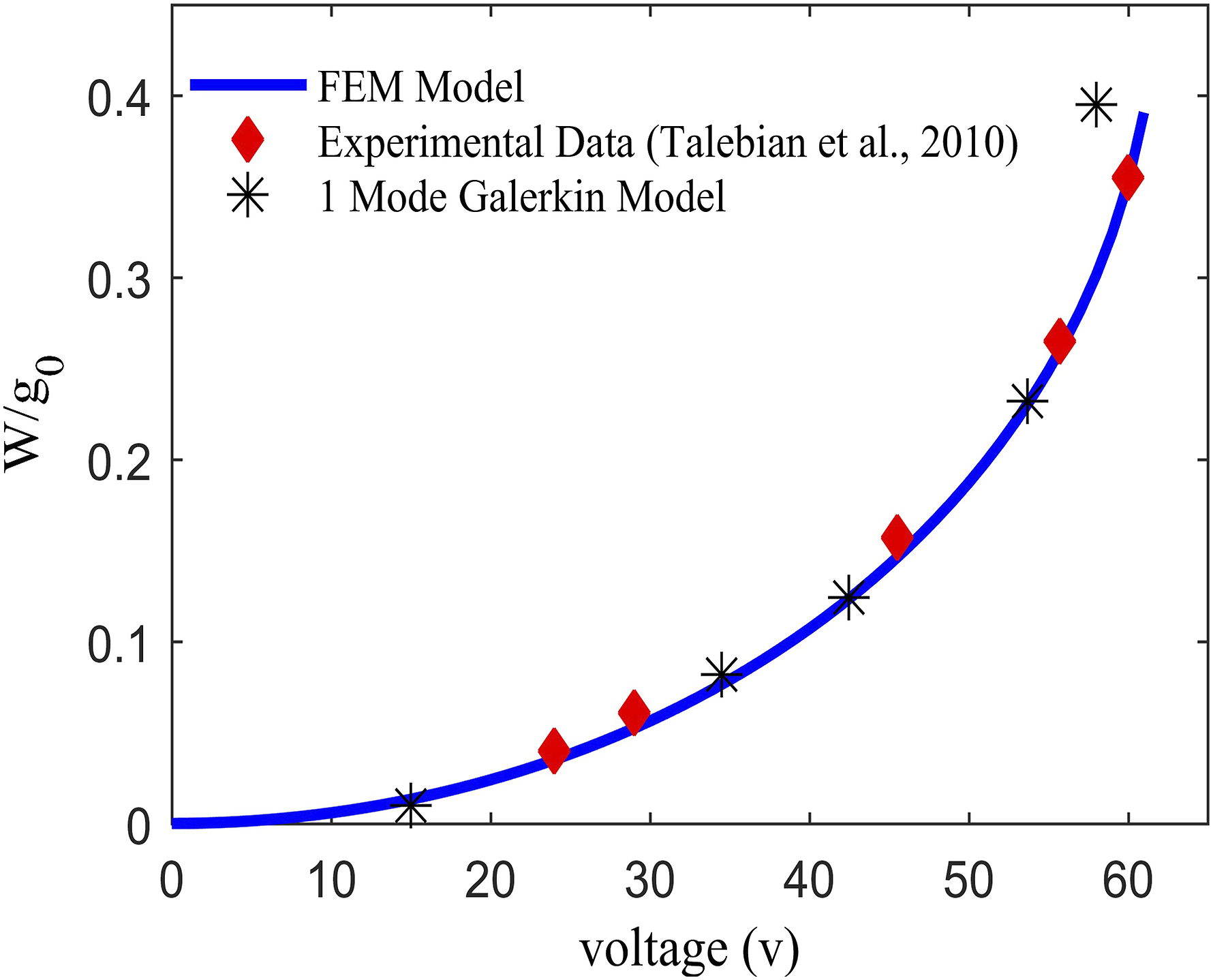
4. Controller design and stability analysis
In this section, two control approaches that are adaptive backstepping sliding mode and adaptive fractional backstepping sliding mode are applied to the system, and the stability of the closed-loop system is investigated. It is important to note that the sliding mode controller, when used alone, is not able to significantly reduce chattering and tracking error. Therefore, more advanced control schemes are proposed and evaluated through simulation.
4.1. ABSMC
To apply the controller, first, the modal dynamics of system equation (14) should be rewritten in the state-space form as follows
The tracking error e1, velocity error e2, and the time derivative of e1 are considered as follows


In the above relation c1 > 0.
It is assumed the desired signal Y
d
is twice the differentiable objective. Differentiating e2 yields To ensure the stability, the first Lyapunov function and its time derivative are written as Setting The second Lyapunov function In equation (24a), the sliding variable S is defined as Therefore, To satisfy 


By considering
Substituting equation (27) into the Lyapunov function Consequently To evaluate the sliding mode gain, the controller uses the upper bound of uncertainties and disturbances which are difficult to estimate. That is why an adaptive algorithm is used to adapt theses values. The third Lyapunov function and the derivative can be expressed as According to the above equation, the controller can be considered as equation (32)


By defining the adaptation law as
Substituting equation (32) into the Lyapunov function Consequently Using the adaptation law, one obtains Because 


The control law, equation (32), guarantees e1, e2, and S converge to zero asymptotically as t converges to infinity (Nwagoum Tuwa and Woafo, 2018b).
According to equation (35), one has Considering that Based on Barbalat lemma, one obtains Therefore, e1, e2, and S converge to zero asymptotically.


4.2. AFBSMC
This section focuses on designing the AFBSMC. For this purpose, first, the procedure from the previous controller design is followed unit until equation (24) is achieved. Then, the sliding variable S and its derivative are defined as


The Caputo derivative is defined as equation (41), (Podlubny, 1998) In the above equation, 
If Caputo fractional derivative with the order of α ∈ R and the range of 0 < α < 1 is integrable on 
If the summation of the order of Caputo fractional derivative becomes one, then (Diethelm, 2010; Kilbas et al., 2006; Li and Deng, 2007)
In the following,
The assumption is that the fractional-order derivative of The derivative of the second Lyapunov function To satisfy 


Based on equation (46), the fractional integral term comes before the switching term, which can change the discontinuous output of the sign function to the continuous one. This leads to a decrease in the chattering of the system.
The control law, equation (46), satisfies
Substituting equation (46) into (45) and using the properties of the Caputo derivative, one obtains Rewriting equation (47) based on Assumption 2 gives Noting γ > σ1, one has Considering γ > σ1, the expression The third Lyapunov function and the derivative can be written as According to the above equation, the controller can be considered as equation (54)


By defining the adaptation law as
Substituting equation (54) in the Lyapunov function Consequently According to the adaptation law and Theorem 4, the following inequality can be concluded Because 


5. Simulation results
In this section, the results of using the ABSMC and AFBSMC approaches on an electrostatic microplate are presented and are compared with the results from the SMC method. The initial conditions and reference trajectory are considered as
5.1. ABSMC simulation results
In this section, we first investigate the effect of bounded noise as an external disturbance on the system. Figure 3(a) shows that increasing the amplitude of the random disturbance results in the increase of the amplitude of vibration of the microplate. As can be seen, at a certain amplitude of the random disturbance (σ = 0.018), the fixed plate shows an unstable behavior and collapses onto the moveable plate because of the presence of the nonlinearity in the electrostatic force (pull-in instability). In Figure 3(b), the effect of MLSP on the dynamic response of the system is depicted. The figure indicates that MLSP is effective on the dynamic response of the system in the presence of the noise. Midpoint deflection time history for the microplate: (a) under different disturbance amplitudes (l = 0.2) and (b) for different material length scale parameter (σ = 0.003).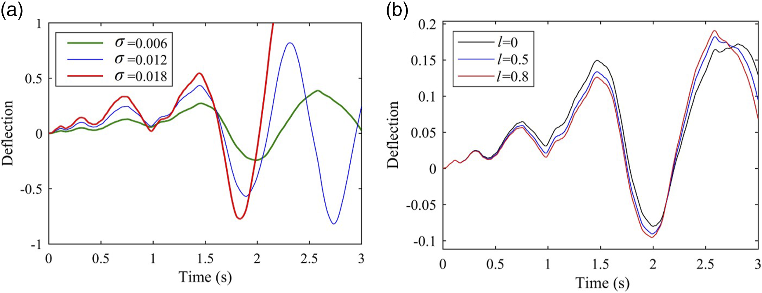
Tracking error is an important factor in assessing the performance of controlling systems, as it describes the ability of the system to follow the desired input. The lower tracking error indicates the higher accuracy of the control system. In Figure 4, the tracking response of the controlled system in the presence of disturbances by the value of Tracking response of the closed-loop system with the adaptive backstepping sliding mode controller: (a) variation of the error, (b) velocity error, and (c) sliding surface.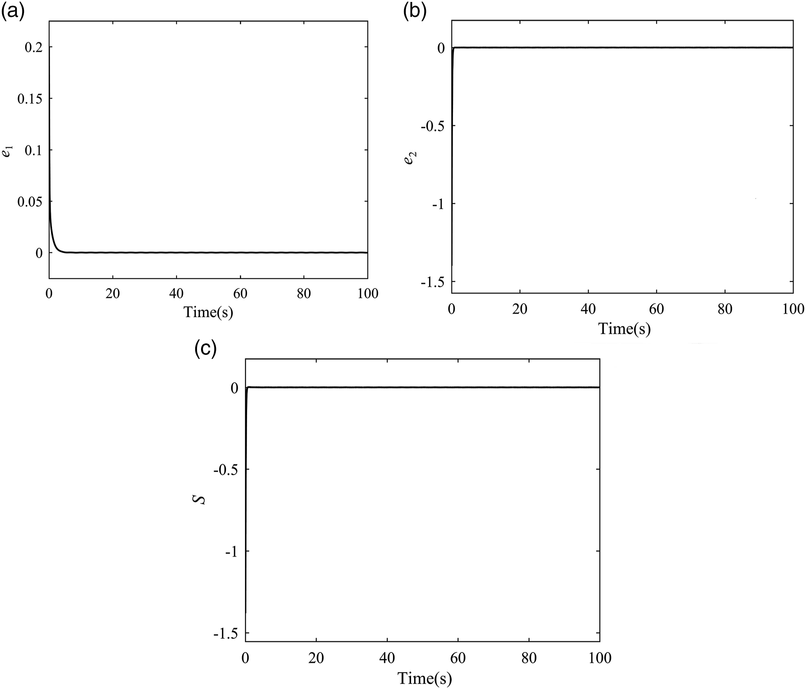
In Figure 5, the variation of the control force and trajectory tracking of deflection for some different values of k1 when γ = 0.001, σ0 = 0.012, and σ
ψ
= 0.1 are investigated. A lower control force can be beneficial to the system because lower control voltage would be needed to suppress the noise, which, in turn, could reduce the cost and weight of the system. It can be seen that by decreasing the value of k1, the lower control force is required during the first 50 s Figure 5(a); also the good tracking performance is achieved Figure 5(b)–(d). Hence, it is possible to improve the performance of the model by adjusting the value of k1. Variation of the control force and trajectory tracking of the microplate deflection: (a) control force, (b) trajectory tracking with k1 = 0.1, (c) with k1 = 10, and (d) with k1 = 100.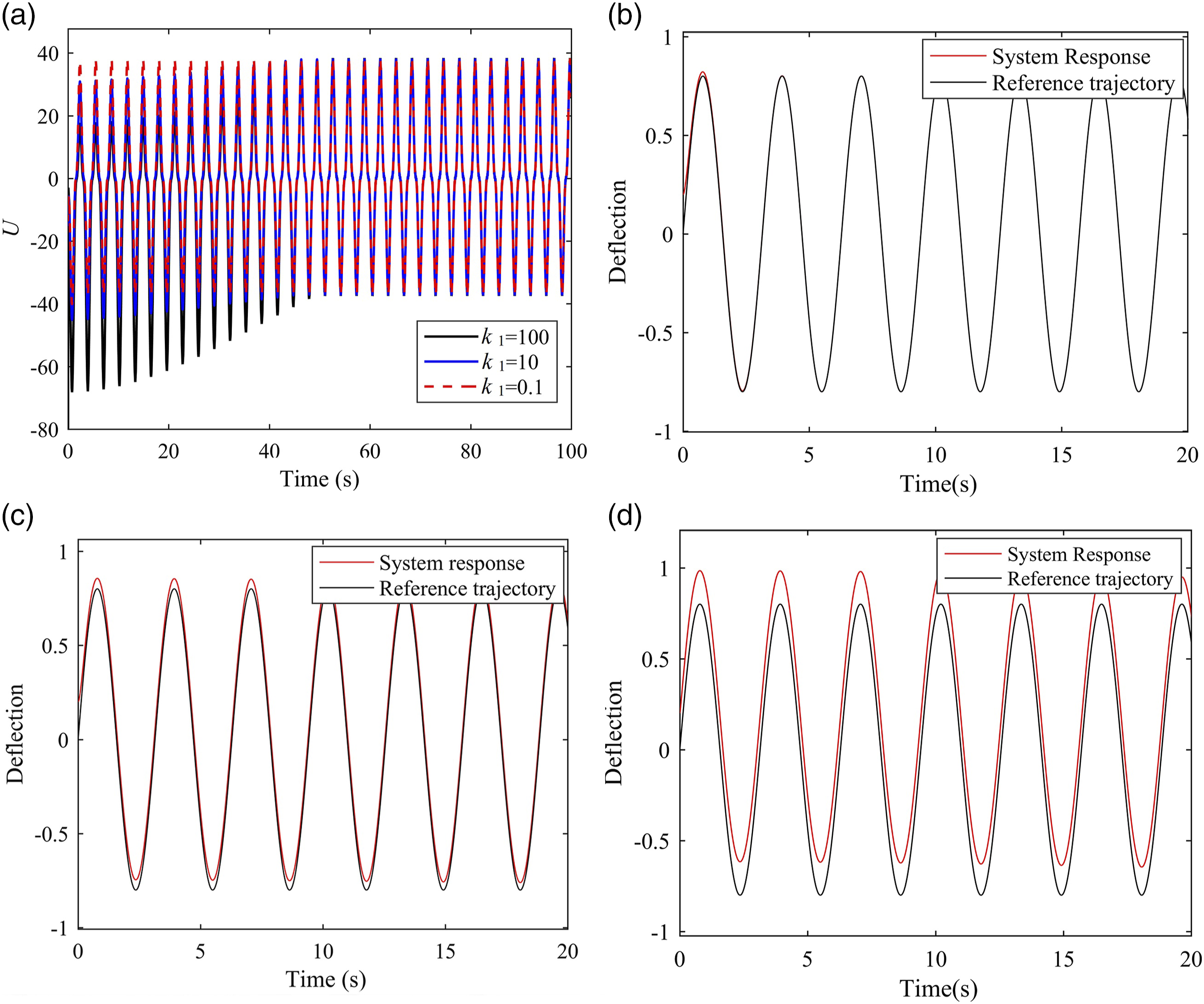
In Figure 6, the variation of the system output and the sliding surface for some different values of γ when k1 = 100, σ0 = 0.012, and σ
ψ
= 0.1 are presented. As is clear, by increasing the value of γ, the tracking performance improves Figure 6(a)–(c) and the sliding surface converges to zero faster although the magnitude of chattering is increased Figure 6(d). The reason is that parameter γ is multiplying to sign function; as a result, with the higher value of the parameter γ, the magnitude of sign function is increased, and as shown in Figure 6(d), the higher magnitude of sign function results in faster convergence and higher magnitude of chattering (Khalil, 2002; Slotine and Li, 1991). From the results presented, it can be concluded that better tracking performance along with faster convergence of sliding surface to zero can be achieved by adjusting the value of γ. Variation of trajectory tracking of the microplate deflection and sliding surface for different values of γ: Trajectory tracking of the microplate deflection with (a) γ = 0.001, (b) γ = 0.1, (c) γ = 5, and (d) sliding surface.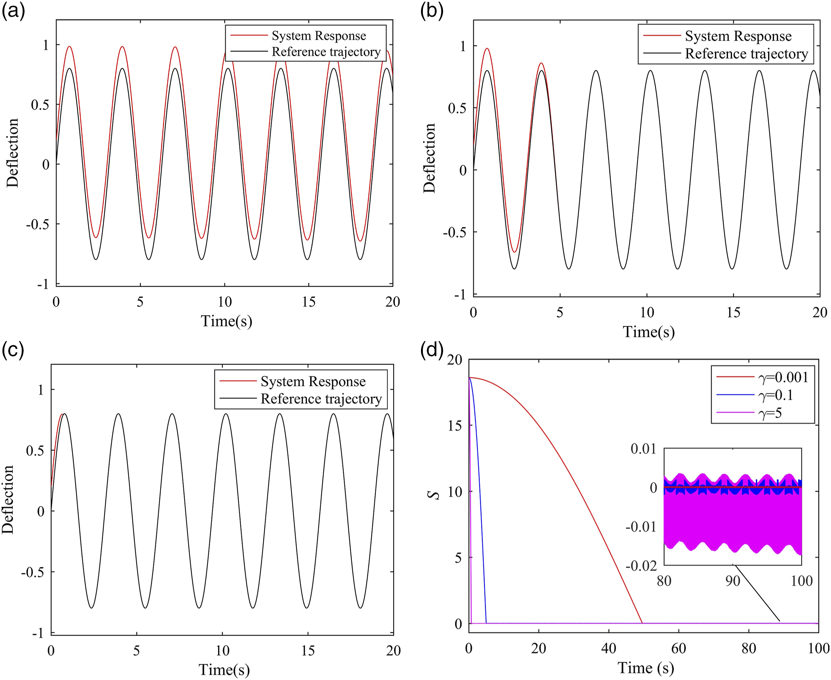
It has been shown that bounded noise can be the origin of chaotic motion and pull-in instability, as shown in Figure 3, in electrostatic MEMS (Nwagoum Tuwa and Woafo, 2018b). In this regard, developing a robust controller to suppress and control undesired motion seems necessary. The robustness of the ABSMC against the random disturbance parameters when k1= 0.1 and γ = 0.001 is investigated in Figure 7(a)–(b). As shown, the variation of disturbance amplitude, which causes pull-in instability, and the variation of the noise intensity, which can lead to the random chaotic motion, have no effect on the controlled system output. Consequently, the robustness of the ABSMC is confirmed. Robustness against the random disturbance parameters: (a) for different amplitudes of noise and (b) for different noise intensities.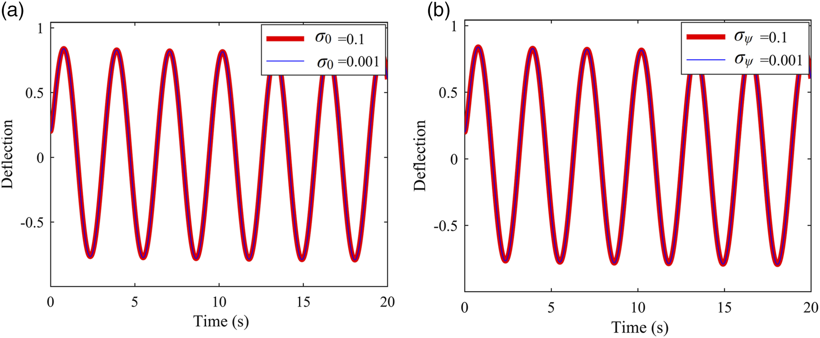
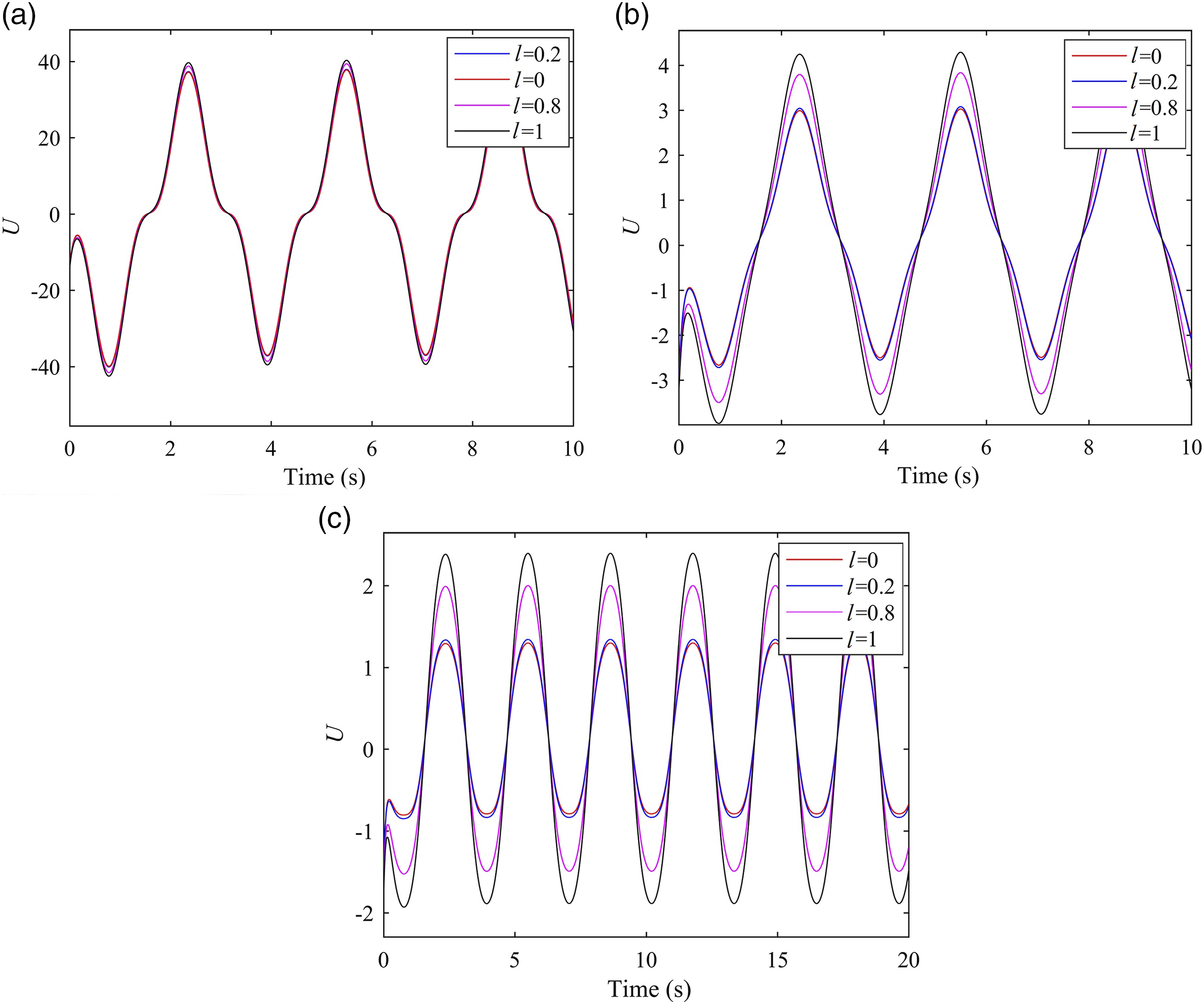
The effect of aspect ratio on the performance of the system is studied in Figure 8. The variation of control force for some different values of width-to-length ratio of microplate is presented in Figure 8. As can be seen, by decreasing the aspect ratio, the lower control force is required, which means that the model with a higher aspect ratio exhibits higher stiffness. Consequently, the lower the aspect ratio, the lower control force is required. In Figure 9, the variation of control force with different values of the size effect parameter for different aspect ratios is investigated. As can be observed, the lower control force is required for the classical plate theory Control force variation for different aspect ratios. Control force variation for different values of material length scale parameter: (a) 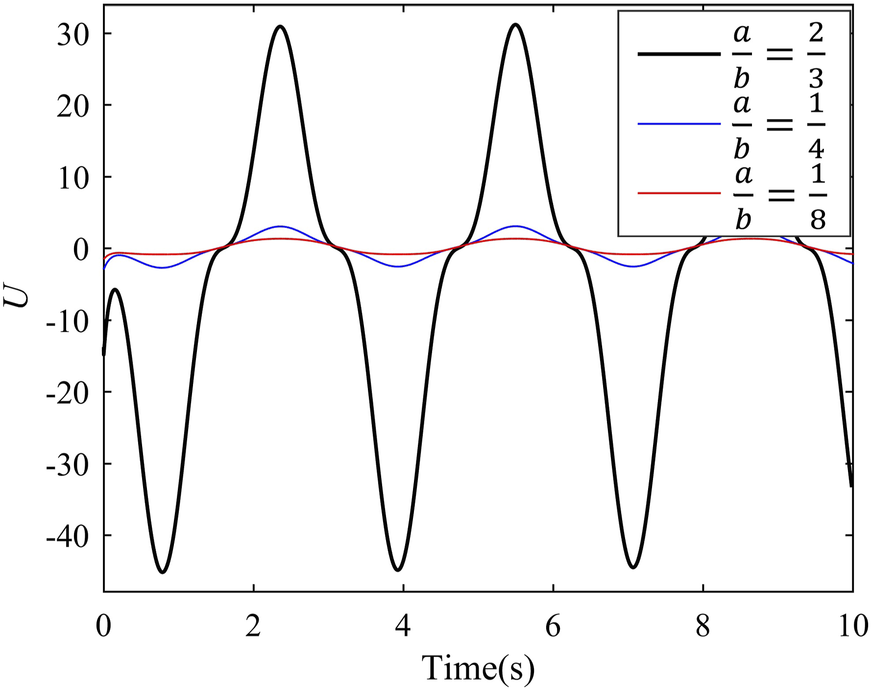
5.2. AFBSMC simulation results
In this subsection, the simulation results of AFBSMC are presented. In Figure 10, the tracking response of the system output in the presence of disturbances when Tracking response of the closed-loop system with the adaptive fractional backstepping sliding mode controller: (a) variation of error, (b) velocity error, and (c) sliding surface.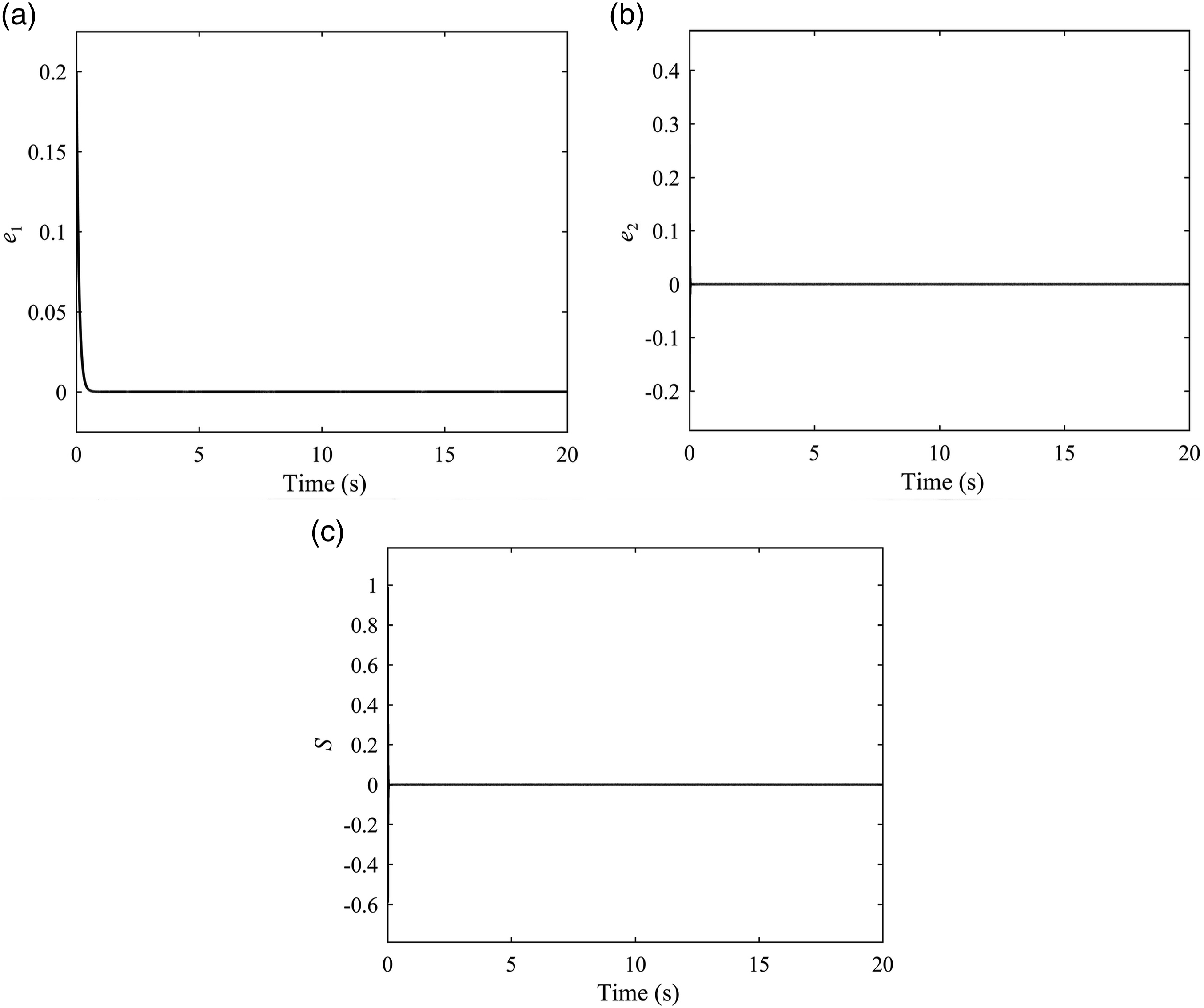
In Figure 11, the variation of the sliding surface, system output, and control force for some different values of α when System response for different orders of Caputo fractional derivative: (a) sliding surface, (b) trajectory tracking response, and (c) control force.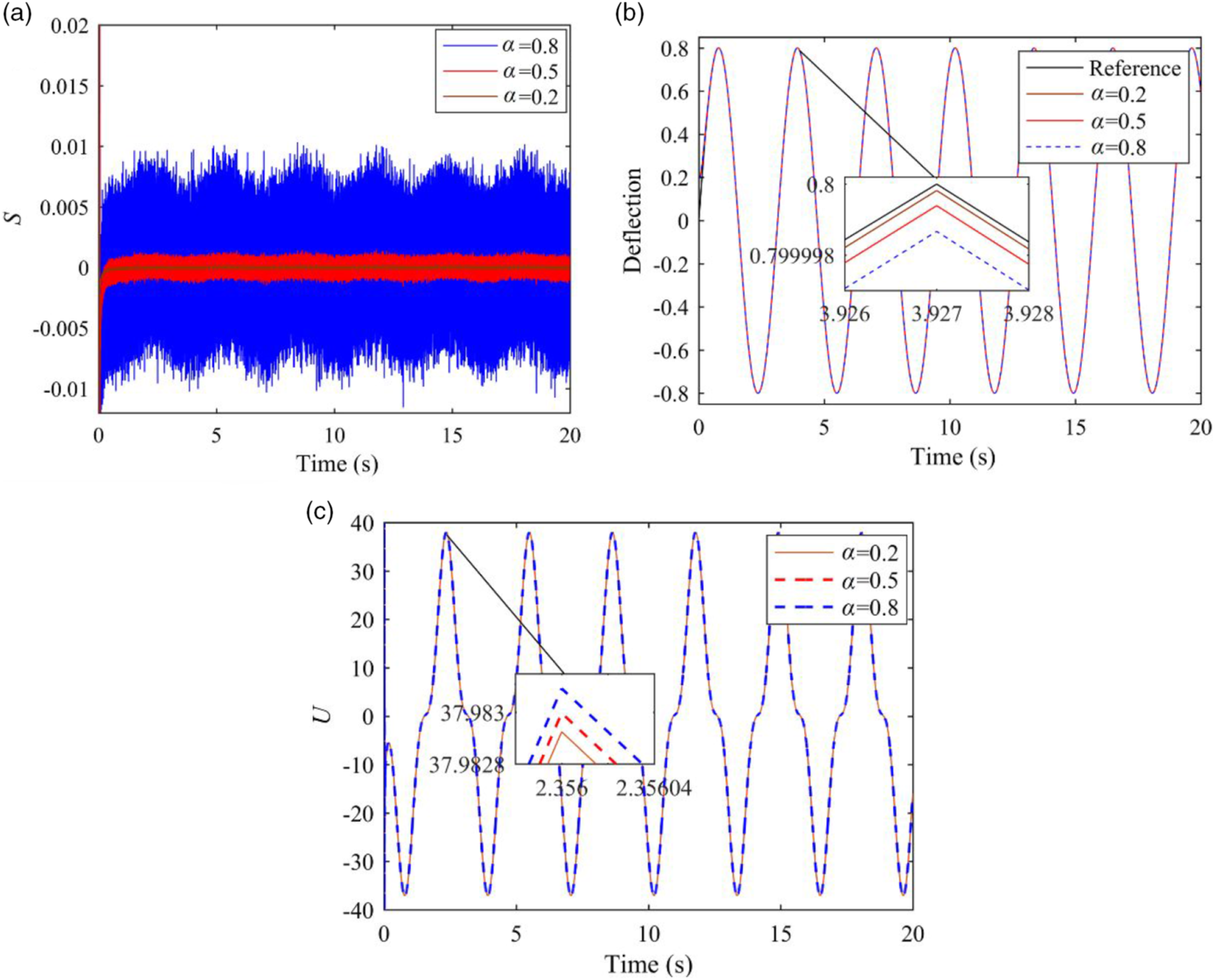
5.3. Comparison of SMC, ABSMC, and AFBSMC methods
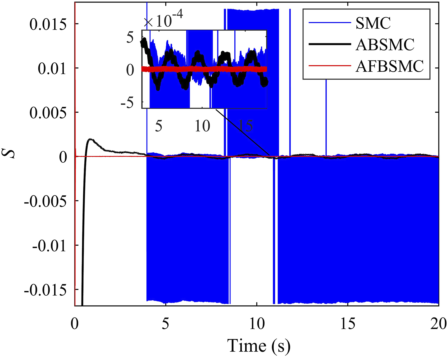
In this subsection, the performances of SMC, ABSMC, and AFBSMC methods are compared with each other. Figure 12(a)–(b) shows the difference in trajectory tracking between SMC, ABSMC, and AFBSMC approaches. Results indicate that the system would have better performance by using the AFBSMC. According to Figure 13, which illustrates the variation of sliding surface with three controllers, the AFBSMC method exhibited the lowest chattering among other schemes. As mentioned before, because a fractional-order sliding surface is used, the amount of chattering is reduced considerably. Trajectory tracking responses for SMC, ABSMC, and AFBSMC methods: (a) variation of deflection and (b) error. SMC: sliding mode control; ABSMC: adaptive backstepping sliding mode controller; AFBSMC: adaptive fractional backstepping sliding mode controller. Sliding surfaces for SMC, ABSMC, and AFBSMC methods. SMC: sliding mode control; ABSMC: adaptive backstepping sliding mode controller; AFBSMC: adaptive fractional backstepping sliding mode controller.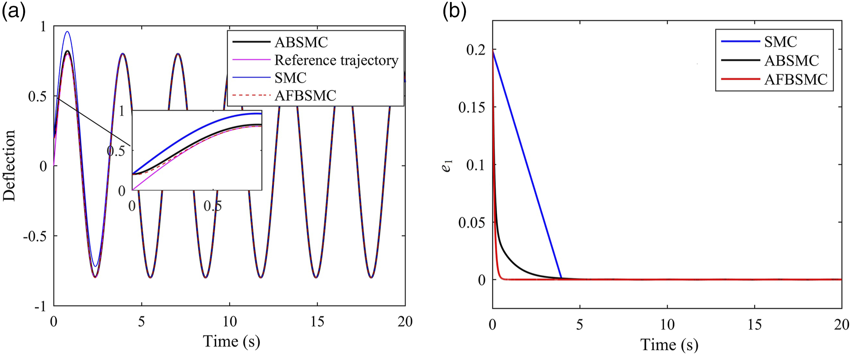
6. Conclusion
In this study, two adaptive nonlinear control approaches are used to control a modified couple stress–based microplate. The control methods are based on the Lyapunov stability criterion to guarantee the stability. In the AFBSMC method, the adaptive control law is used to evaluate the upper bound of uncertainties and random disturbances; in addition, in the AFBSMC method, the fractional-order form of sliding surface is used to reduce the amount of chattering and also to improve the tracking error.
Obtained results indicate that greater the aspect ratio and lower the size effect parameter, the less control force is required to stabilize the system. In addition, the variation of disturbance amplitude and noise intensity have no effect on the controlled output, which verifies the robustness of the controller. Furthermore, by increasing the value of fractional order, the magnitude of chattering increases, but it does not have a considerable effect on the control force and tracking performance. Finally, the effectiveness of the AFBSMC scheme is compared with SMC and ABSMC approaches. The simulation results demonstrate the superiority of the AFBSMC approach in reducing tracking error and chattering in comparison to the conventional SMC or ABSMC methods.
Footnotes
Declaration of conflicting interests
The author(s) declared no potential conflicts of interest with respect to the research, authorship, and/or publication of this article.
Funding
The author(s) received no financial support for the research, authorship, and/or publication of this article.

Appendix 1
Following the steps provided in (Kazemi et al., 2017a, 2017b), the resultant forces and moments can be obtained in the form of the displacement field as
Appendix 2
The Hermite shape functions for a rectangular element with side coordinates