






Abstract
The vibration response of a damped linear system is always calculated based on the mode superposition method. However, the construction of the damping matrix is difficult for the conventional mode superposition methods based on the viscous damping model, and this problem is much more serious for nonproportionally damped linear systems. The damping matrix based on the hysteretic damping model is easy to construct and unique, which is determined only by the structural stiffness and material loss factor. The time-domain motion equation of a multi-degree-of-freedom nonproportionally damped linear system is easily constructed based on the hysteretic damping model. According to the characteristics of external excitation, the general solution of the corresponding homogeneous equation and special solution of the corresponding nonhomogeneous equation can be solved. By the aid of the easiness of the damping matrix, a complex mode superposition method based on the hysteretic damping model is proposed for the nonproportionally damped linear system. Based on the proposed method, a user subroutine in ANSYS and MATLAB is developed to calculate vibration responses in time-domain dynamic analyses. A shaking table test of a cantilever plate composed of host and damping layers is conducted to validate the proposed method. The method proposed in this article is unconditionally convergent, and its convergence is independent of the time step of time-domain analyses. Compared with the common complex mode superposition method based on the viscous damping model, the simulation results of the proposed method are closer to the test results, and its accuracy and efficiency are higher. In addition, the calculation results of the proposed method are unique, which is irrelevant to the choice of vibration modes.
Keywords
Highlights
A complex mode superposition method for hysteretic nonproportionally damped linear systems is proposed. The proposed complex mode superposition method is unique and has high computation efficiency. The proposed complex mode superposition method is irrelevant to the choice of vibration modes. Different complex mode superposition methods of nonproportionally damped linear systems are analyzed. The user subroutines in ANSYS and MATLAB are developed in time-domain dynamic analyses. A shaking table test is conducted to validate the proposed method.
1. Introduction
To improve performance against strong wind or earthquake ground motion, many building structures can be equipped with viscoelastic dampers (Lee et al., 2002) or different damping materials (Huang et al., 2015). These hybrid structures have one feature in common. The damping is inherently nonproportional. The damping matrices are not proportional to the mass and/or stiffness matrices in hybrid structures with multiple material damping characteristics. This type of damping is always classified as nonproportional damping (Jones, 2001; Nasif et al., 1985). The methods dealing with the problem can be classified into two categories: the real mode superposition method of approximately proportionally damped linear systems and the complex mode superposition method of nonproportionally damped linear systems (Villaverde, 1997).
For the first case, the nonproportionally damped linear systems can be approximately regarded as proportionally damped linear systems. The commonly used calculation method is based on the Caughey damping model (Caughey and O’Kelly, 1965), which is a generalized Rayleigh damping model (Strutt, 1945). The Caughey damping coefficients are obtained by finite element modes (Pant et al., 2013; Ryan and Polanco, 2008). The real mode superposition method can be directly applied in the Caughey damping model (Bilbao et al., 2006; Cruz and Miranda, 2017). However, the method has two shortcomings. The first is that the method depends on the choice of appropriate modes; specifically, the Caughey damping matrix is not unique. The second shortcoming is that the damping ratios are underestimated or overestimated in the frequency range of interest, and the calculated dynamic responses are overestimated or underestimated. To solve the question about the nonuniqueness of the real mode superposition method based on the Rayleigh damping model, a real mode superposition method based on the equivalent modal damping ratio was proposed (Chopra, 2001). The equivalent modal damping ratio was determined approximately through a structural energy-weighted function (Feriani and Perotti, 1996; Shen et al., 1995; Wang, 2009). However, this method is a forced decoupling method and cannot be applied to large damping ratio or large-scale systems because the calculation error is difficult to control.
In theory, mode vectors of nonproportionally damped linear systems are complex mode vectors rather than real mode vectors (Liang and Lee, 1991; Villaverde, 1988). Thus, the viscous damping motion equations of these systems can be transformed to first-order differential equations by state-space modeling. The corresponding complex mode superposition method is obtained as a result of complex modal orthogonality (De Domenico and Ricciardi, 2019; Foss, 1958; Igusa et al., 1984; Neugebauer et al., 2011; Papageorgiou and Gantes, 2010). However, the construction of a reasonable damping matrix is very difficult (Clough and Penzien, 2003). The viscous damping model exhibits the unreasonable physical phenomenon that the energy dissipation in one cycle of harmonic vibration is proportional to the structural frequency (Bert, 1973; Crandall, 1970). This shortcoming leads to the difficulty in the construction of a damping matrix because it is related to the selection of reasonable structural frequency. In addition, the dimension of the matrix is doubled, and the computation cost is large.
Compared with the viscous damping model, the damping matrix of the hysteretic damping model can be more easily determined. Theodorsen and Garrick (1940) proposed a hysteretic damping model, also called a complex damping model. This model guarantees that the energy losses per cycle are independent of structural frequencies as observed in material experiments and building observations (Bert, 1973; Crandall, 1970). Therefore, the construction of the damping matrix based on the hysteretic damping model is determined only by material loss factors and the stiffness of the system. Regarding time-domain analysis, Inaudi and Kelly (1995) proposed a time-domain calculation method based on the Hilbert transform method. However, the method is only applied in a hysteretic proportionally damped linear system. In addition, the method is a time-domain step-by-step numerical method, which cannot consider the influences of structural natural frequency and vibration frequency of external excitation.
In this article, according to the characteristics of external excitation, a complex mode superposition method based on the hysteretic damping model is proposed and can be applied to nonproportionally damped linear systems. A user subroutine in ANSYS and MATLAB based on the proposed method is developed to calculate vibration responses. The proposed method is unconditionally stable and has high computational efficiency (Section 2). The results of the shaking table test are discussed to verify the proposed method in Section 3, and the differences between conventional mode superposition methods and the proposed method have been identified.
2. Complex mode superposition method for a nonproportionally damped system
2.1. Complex mode superposition method based on the Rayleigh damping model
The damping matrix of a nonproportionally damped system is not orthogonal, so the traditional real mode superposition method is no longer applicable. The viscous damping model is one of the most commonly used damping models. Several researchers have suggested that combined with the state-space method, a complex mode superposition method based on the viscous damping model can be realized, which can be applied to nonproportionally damped systems (De Domenico and Ricciardi, 2019; Foss, 1958; Igusa et al., 1984; Neugebauer et al., 2011; Papageorgiou and Gantes, 2010).
Based on the viscous damping model, the time-domain motion equation of the multidegree-of-freedom (MDOF) system is given by
Rayleigh damping is the most common method based on the viscous damping model. Based on the Rayleigh damping, the damping matrix of a nonproportionally damped system is expressed as (Papageorgiou and Gantes, 2010, 2011)
The damping ratio is half of the material loss factor (Lin and Zhu, 2009), and it is expressed as
By means of state-space modeling (Foss, 1958), the auxiliary equation is introduced as
Equations (1) and (5) are combined as
Equation (6) can be directly solved by the complex mode superposition method. Thus, a complex mode superposition method based on the Rayleigh damping model (CR) can be realized.
2.2. Complex mode superposition method based on the hysteretic damping model
CR is realized in the state space, rather than in the physical space, and the amount of calculation will be very large. Besides, equations (2) and (3) show that the determination of the damping matrix depends on the choice of modes. To overcome these shortcomings, this article is devoted to propose a complex superposition method based on the hysteretic damping model.
The frequency-domain motion equation of the MDOF system based on the hysteretic damping model is given by (Inaudi and Kelly, 1995)
Here,
The construction of a damping matrix based on the hysteretic damping model is determined only by the structural stiffness and material loss factor. The damping matrix is expressed as
By the Fourier transform method, equation (7) is rewritten as
Equation (12) is substituted into (10), which is rewritten as
The general solution of equation (13) is expressed as
Equation (14) is substituted into (13), which is decomposed into
By the Hilbert transform method, equation (15) can be rewritten as
It is assumed that
Equation (18) is equivalent to
From equation (20), the corresponding complex eigenvectors are given by
Equation (22) is substituted into (20), which can be rewritten as
From equation (23), the results are obtained as
The vibration frequency of
Then, equation (16) is rewritten as
Both sides of equation (29) are multiplied by
By the orthogonality of the complex eigenvectors, equation (30) is rewritten as
By the Hilbert transform method, equation (17) can be rewritten as
It is assumed that
Equation (32) is equivalent to
Equation (35) is substituted into equation (34), which can be rewritten as
It is assumed that
The results are obtained as
From equations (39)–(41), the solution of (10) is rewritten as
Hence, a complex mode superposition method based on the hysteretic damping model (CH) is realized, which can be directly applied to a nonproportionally damped system. The procedure of this method is presented in Figure 1. The problem of determining the initial conditions of MDOF systems should be solved first. Flow chart of the proposed complex mode superposition method based on the hysteretic damping model.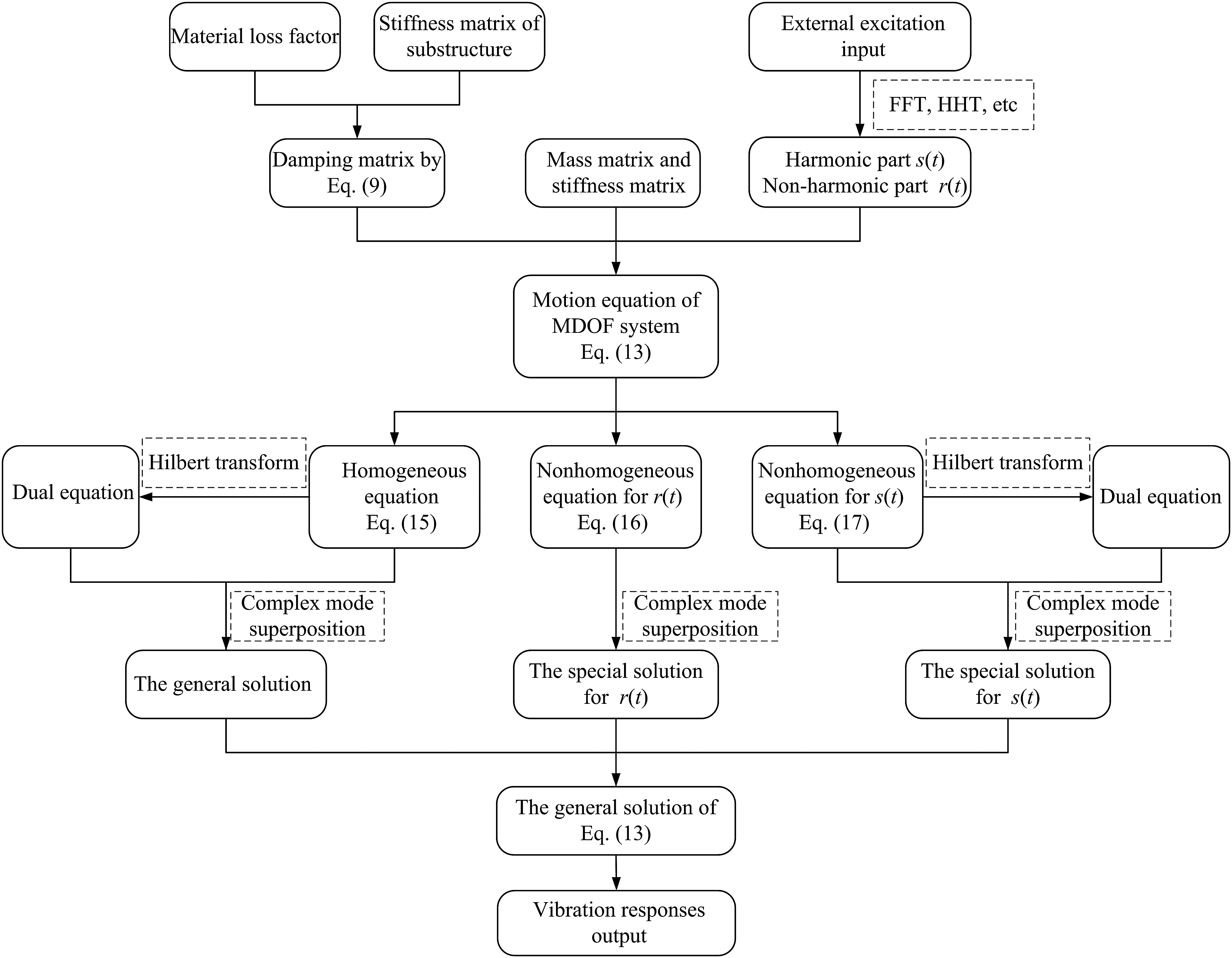
From equation (43), the results are obtained as
Equations (44) and (45) are substituted into (42). The results are obtained as
Combined with finite element modeling (Naghinejad and Ovesy, 2019; Wang and Wang, 2016), the numerical simulation of CH can be realized. The user subroutines in ANSYS and MATLAB are developed to calculate vibration responses in time-domain dynamic analyses. The algorithm of the user subroutines in ANSYS and MATLAB is presented in Figure 2. Algorithm of the user subroutines in ANSYS and MATLAB.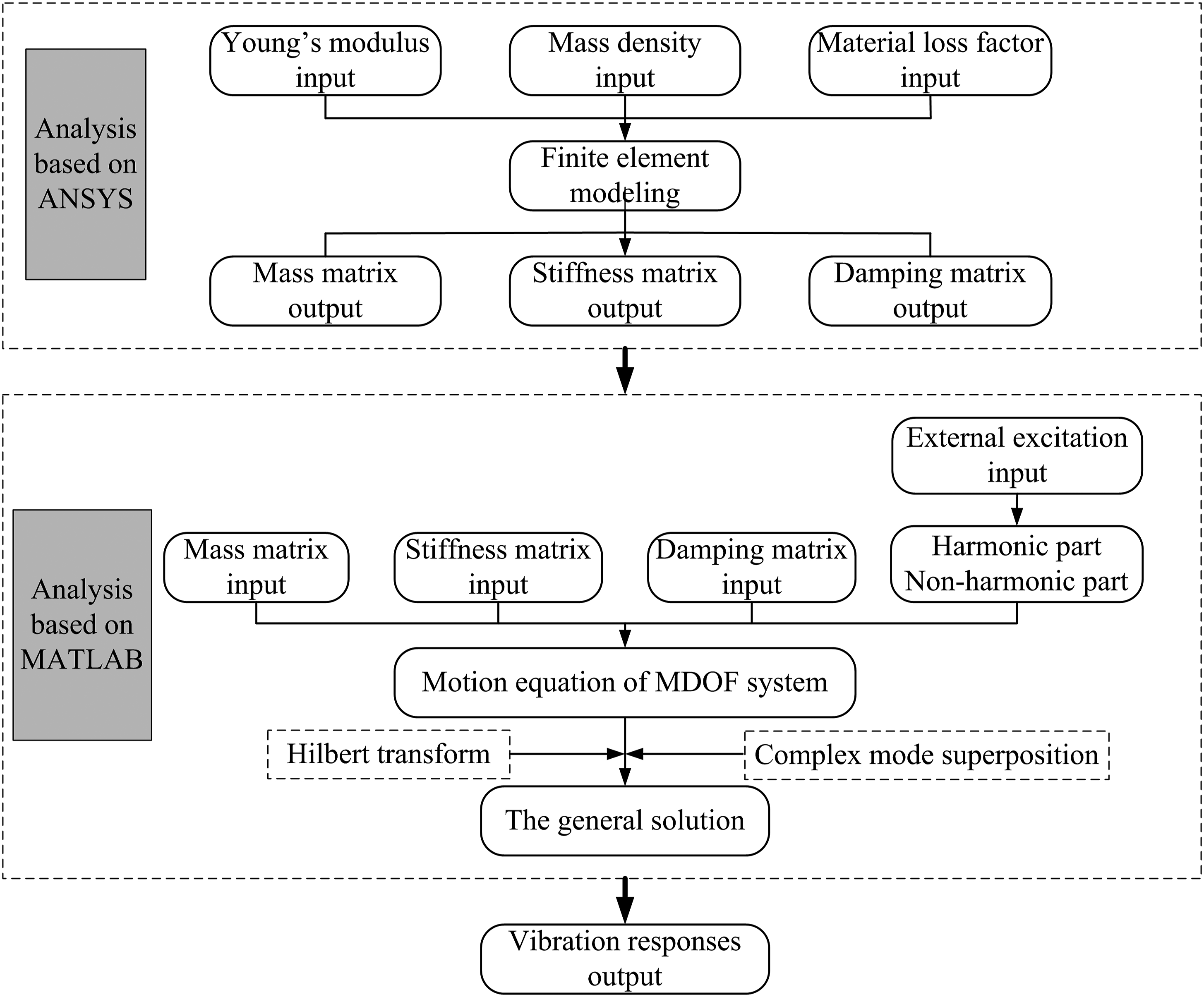
Comparisons of different methods.

Note: CH: complex mode superposition method based on the hysteretic damping model; CR: complex mode superposition method based on the Rayleigh damping model; FD: finite difference; DSC: discrete singular convolution; HDQ: harmonic differential quadrature.
3. Experiment examples
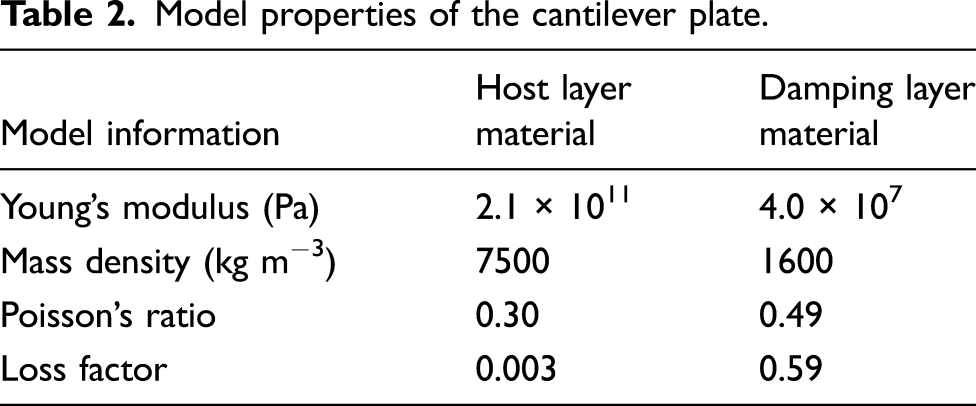
The nonproportionally damped model is used with a cantilever plate composed of host and damping layers. The host layer is made of steel plate, and the damping layer is made of high-molecular polymer. There is a thin layer of damping rubber between the host layer and damping layer, which can make the host and damping layers work together very effectively. Numerical simulation and experiment analysis are performed on the cantilever plate. The purpose behind these experiment example studies is to verify the accuracy of CH. Two identical specimens (specimen CP-1 and specimen CP-2) are used in the test. The structural dimension of the specimens is shown in Figure 3. The bottom of the specimen is fixed and subjected to axial (X-axis) dynamic excitation. The basic physical information is listed in Table 2. Schematic of the cantilever plate. Model properties of the cantilever plate.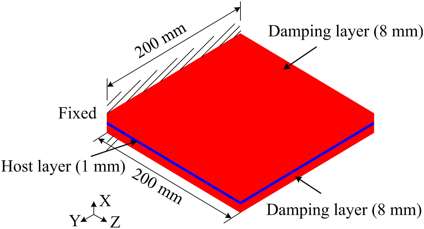
The energy losses per cycle are independent of structural frequencies as observed in material experiments within a wide frequency range (Bert, 1973; Crandall, 1970) so that the material loss factor is approximately constant. With the aid of material damping tests, from 5 Hz to 200 Hz, the loss factor of the host layer material is approximately 0.003, and the loss factor of the damping layer material is approximately 0.59.
Figure 4(a) shows that the vibration test system includes a signal collecting system, laser Doppler vibration measurement system, shake table, and control system. FNV-R4D-VD1 of the HoloBright company in Singapore is adopted in the laser Doppler vibration measurement system. The velocity time–history of four vibration points in the specimen can be obtained at the same time. The locations of the vibration points are shown in Figure 4(b). Because these points are symmetric, for convenience, only the vibration responses of points A and B are analyzed. Schematic of vibration test: (a) vibration test system and (b) locations of vibration points.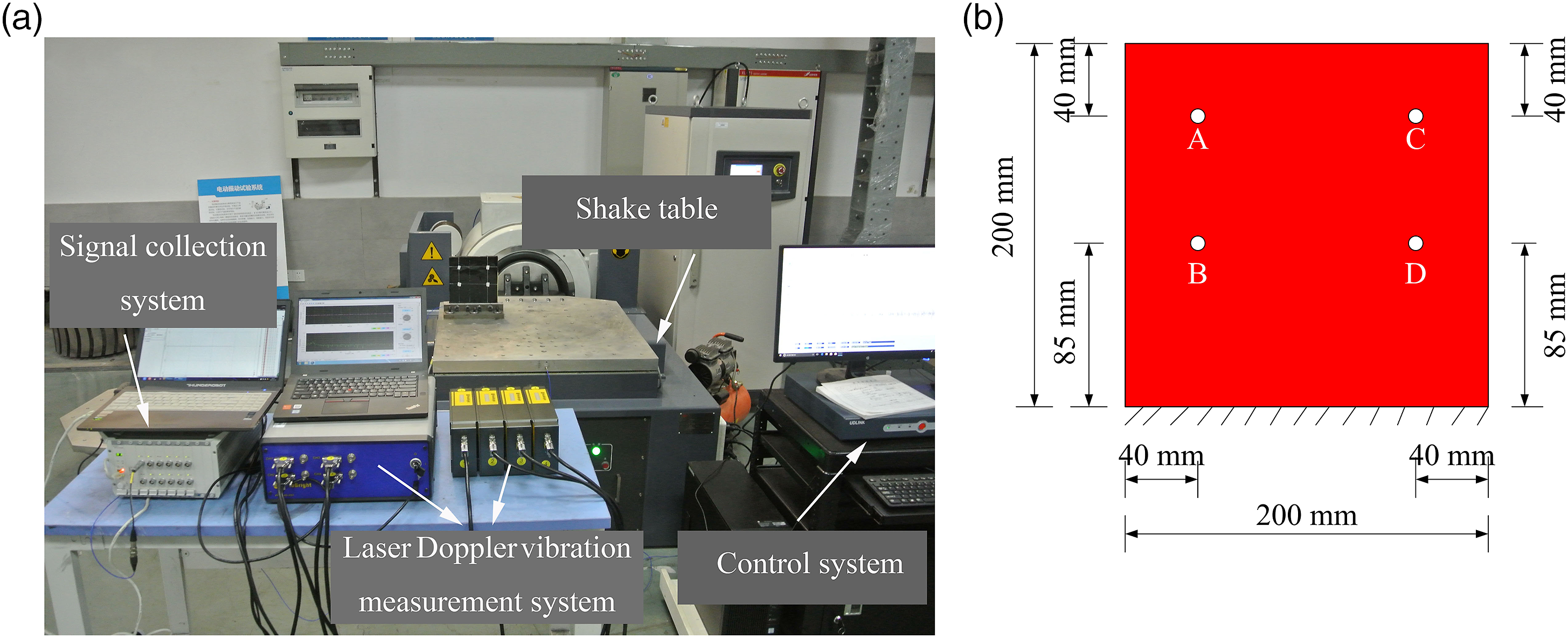
3.1. Frequency response curve
The structural steady-state vibration response is an important aspect of the structural vibration response. To verify the proposed method, the frequency response curves of different methods are analyzed. CR requires the choice of modes. Complex mode superposition method of Rayleigh damping model based on the first and the second modes (CRS) is adopted, and the method based on the first and the third modes (CRT) is also used for comparison. The frequency response curves of specimens CP-1 and CP-2 are obtained by the sine sweeping-frequency vibration method in the test. The dynamic excitation is the X-direction relative wave. The frequency of excitation vibration increases from 80 Hz to 120 Hz. The rate of frequency increase is 0.5 Hz/s. The peak acceleration of the excitation vibration is 9.8 m/s2.
Following the methods mentioned above, the amplitude–frequency characteristic curves and phase–frequency characteristic curves for the third mode are obtained, as shown in Figures 5 and 6. Because of the discreteness of material properties and manufacturing errors of the test specimens, there are some differences between the velocity frequency response curves of specimens CP-1 and CP-2. The velocity amplitude–frequency response results of the different methods are shown in Tables 3 and 4. Amplitude–frequency characteristic curves: (a) point A and (b) point B. Phase–frequency characteristic curves: (a) point A and (b) point B. Velocity amplitude–frequency response results of point A by different methods. Note: Velocity amplitude–frequency response results of point B by different methods. Note: 
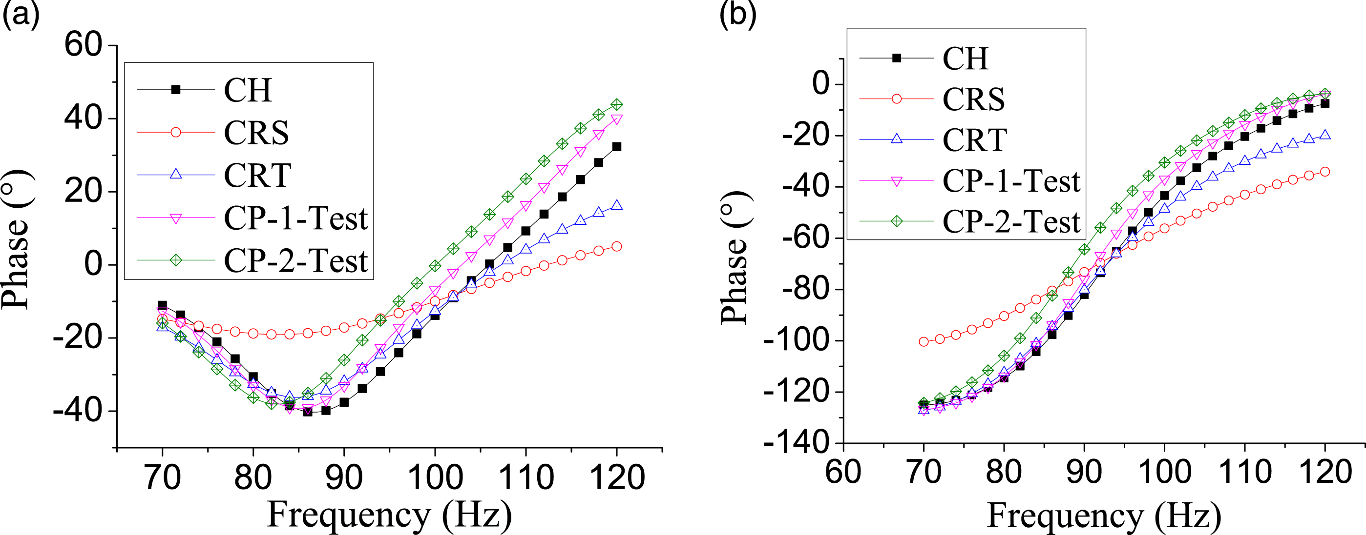
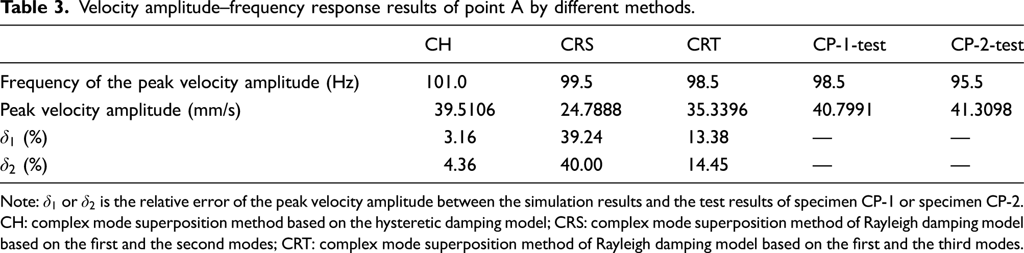
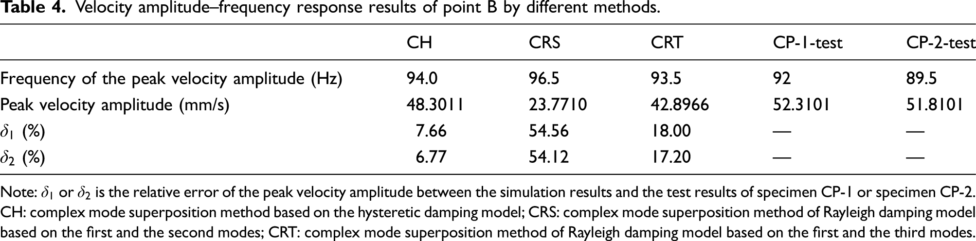
Compared with the test results, the maximum relative errors of peak velocity amplitudes based on CRS and CRT are 54.56% and 18.00%, respectively. The phase–frequency characteristic curve of CRS is obviously different from the test results. For CR, the simulation results of CRT are more similar to the test results than those of CRS. The reason is that the frequency of the third mode is between 80 Hz and 120 Hz. The choice of the first mode and the third mode is reasonable. For CR, the damping ratios are underestimated or overestimated in the frequency range of interest (Ryan and Polanco, 2008), and the corresponding calculation results will be overestimated or underestimated. Regarding the shortcoming of the Rayleigh damping model, compared with the result of other mode, the modal damping ratio of the third mode based on CRS is larger, and the vibration responses are smaller. Therefore, the results of CR do not exhibit uniqueness, and the choice of reasonable modes based on the Rayleigh damping model is very important.
The simulation results of CH and the test results have great consistency. The maximum relative error of peak velocity amplitudes based on CH is only 7.66%. The error of the phase–frequency characteristic curve of CH is the smallest compared with the test results. For CH, the structural loss factor is among material loss factors, and the damping ratios are not underestimated or overestimated in the interested frequency range. The computational accuracy of CH is higher than that of CR. In addition, the calculation results of CH are unique, and the problem of the choice of reasonable modes is avoided.
3.2. Vibration responses under random excitation
In the sine sweeping-frequency vibration method, the structural vibration responses are mainly steady-state vibration responses, and the proportion of structural transient state responses is small. The frequency response curves cannot reflect the general situation of structural vibration. Therefore, the structural vibration responses under random excitation are analyzed. The vibration frequency of the random excitation is set from 40 Hz to 150 Hz. The random excitation of specimen CP-1 (random excitation (1)) and that of specimen CP-2 (random excitation (2)) can be obtained by a signal collection system. These random excitations and corresponding Fourier transform spectrum are shown in Figure 7. Then, the simulated velocity time-history responses of CH and CR under random excitation (1) or random excitation (2) can be calculated. The structural velocity time-history responses have been obtained by a laser Doppler vibration measurement system as described above. Random excitation of specimens: (a) acceleration time-history of random excitation (1), (b) Fourier transform spectrum of random excitation (1), (c) acceleration time-history of random excitation (2) and (d) Fourier transform spectrum of random excitation (2).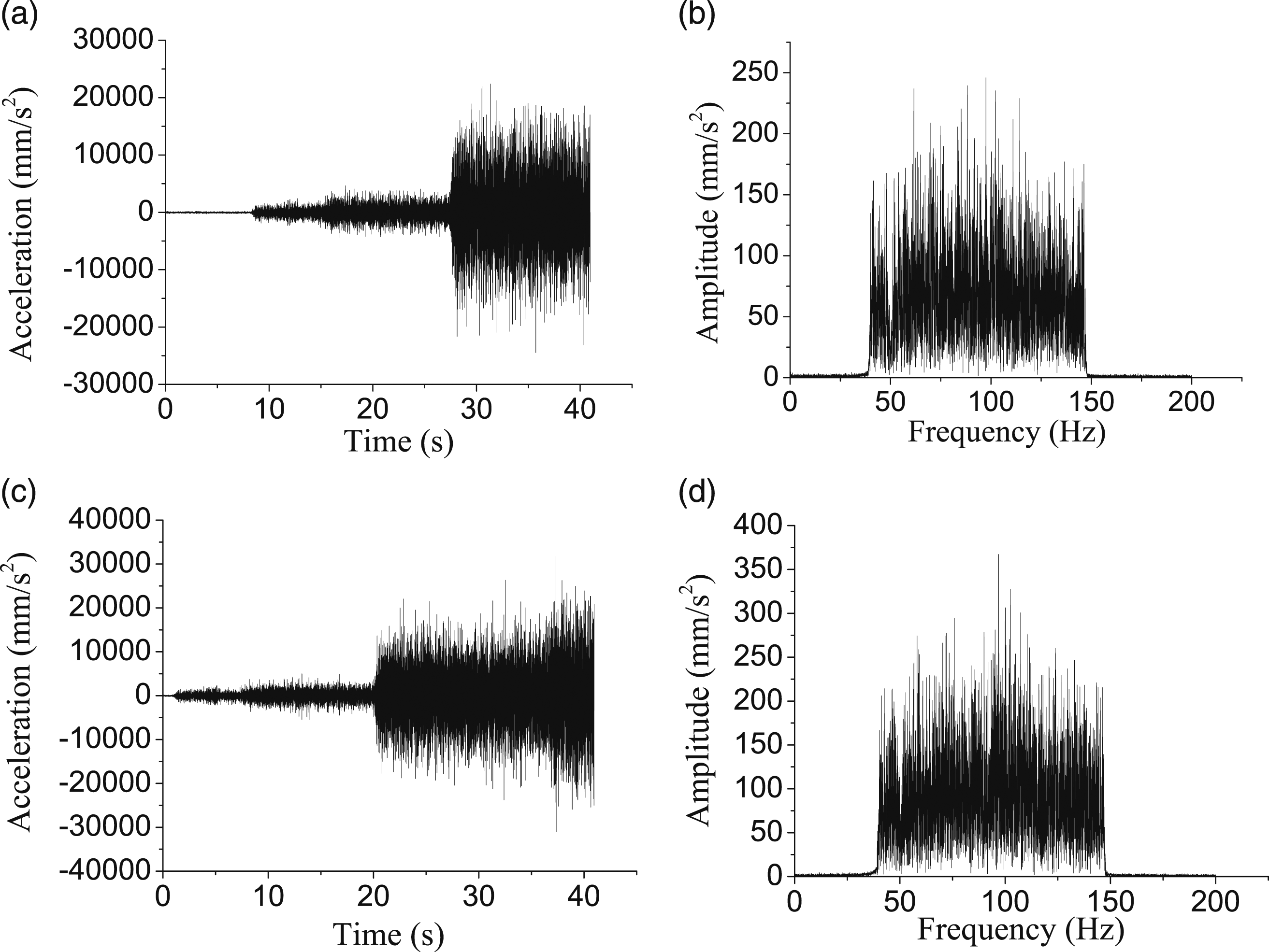
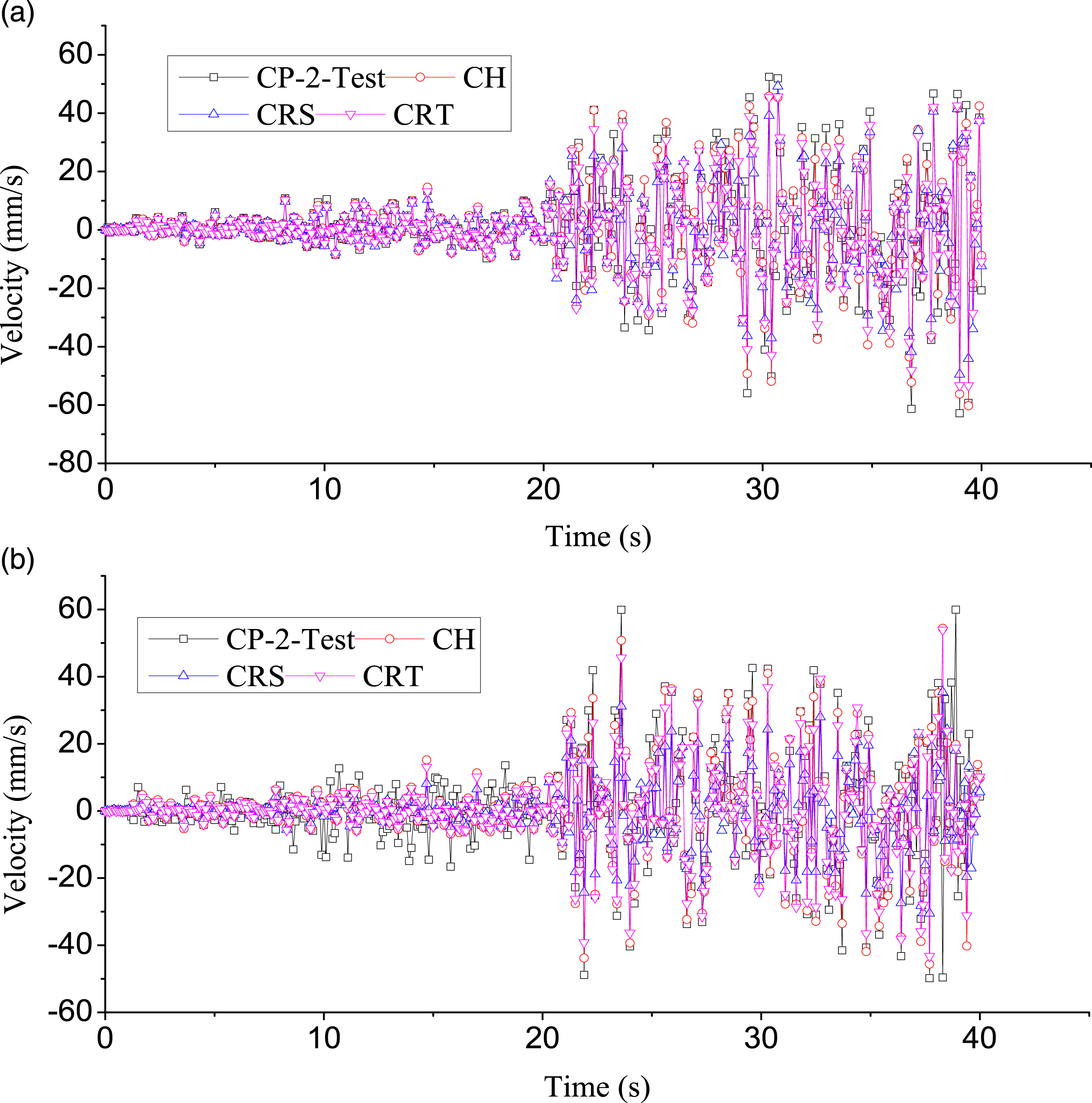
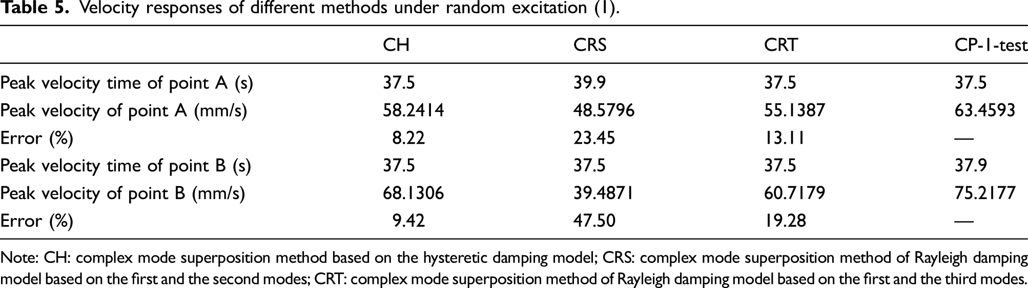
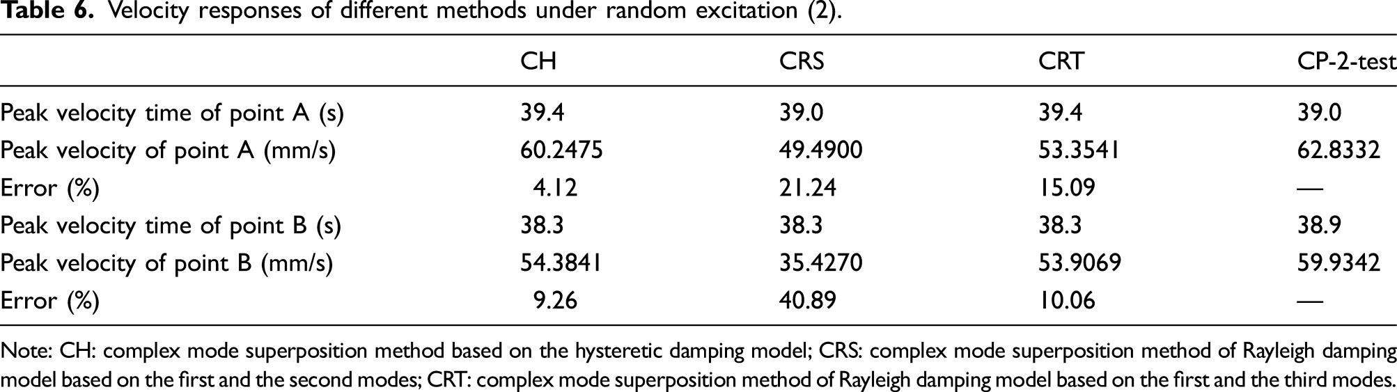
The results shown in Figures 8 and 9 indicate that the characteristics of the structural vibration responses under random excitation are similar to those of structural steady-state vibration responses. The problem of the choice of reasonable modes is avoided based on CH. In Tables 5 and 6, compared with CR, the relative errors of peak velocity responses of CH are smaller. Figures 8 and 9 indicate that the simulation velocity time-history responses of CH are closer to the test results than those of CR. Therefore, the calculation accuracy of CH is higher. In addition, CH does not need the aid of state-space modeling method, and the computational efficiency of CH is relatively high. Velocity time–history curves under random excitation (1): point A and (b) point B. Velocity time–history curves under random excitation (2): point A and (b) point B. Velocity responses of different methods under random excitation (1). Note: CH: complex mode superposition method based on the hysteretic damping model; CRS: complex mode superposition method of Rayleigh damping model based on the first and the second modes; CRT: complex mode superposition method of Rayleigh damping model based on the first and the third modes. Velocity responses of different methods under random excitation (2). Note: CH: complex mode superposition method based on the hysteretic damping model; CRS: complex mode superposition method of Rayleigh damping model based on the first and the second modes; CRT: complex mode superposition method of Rayleigh damping model based on the first and the third modes.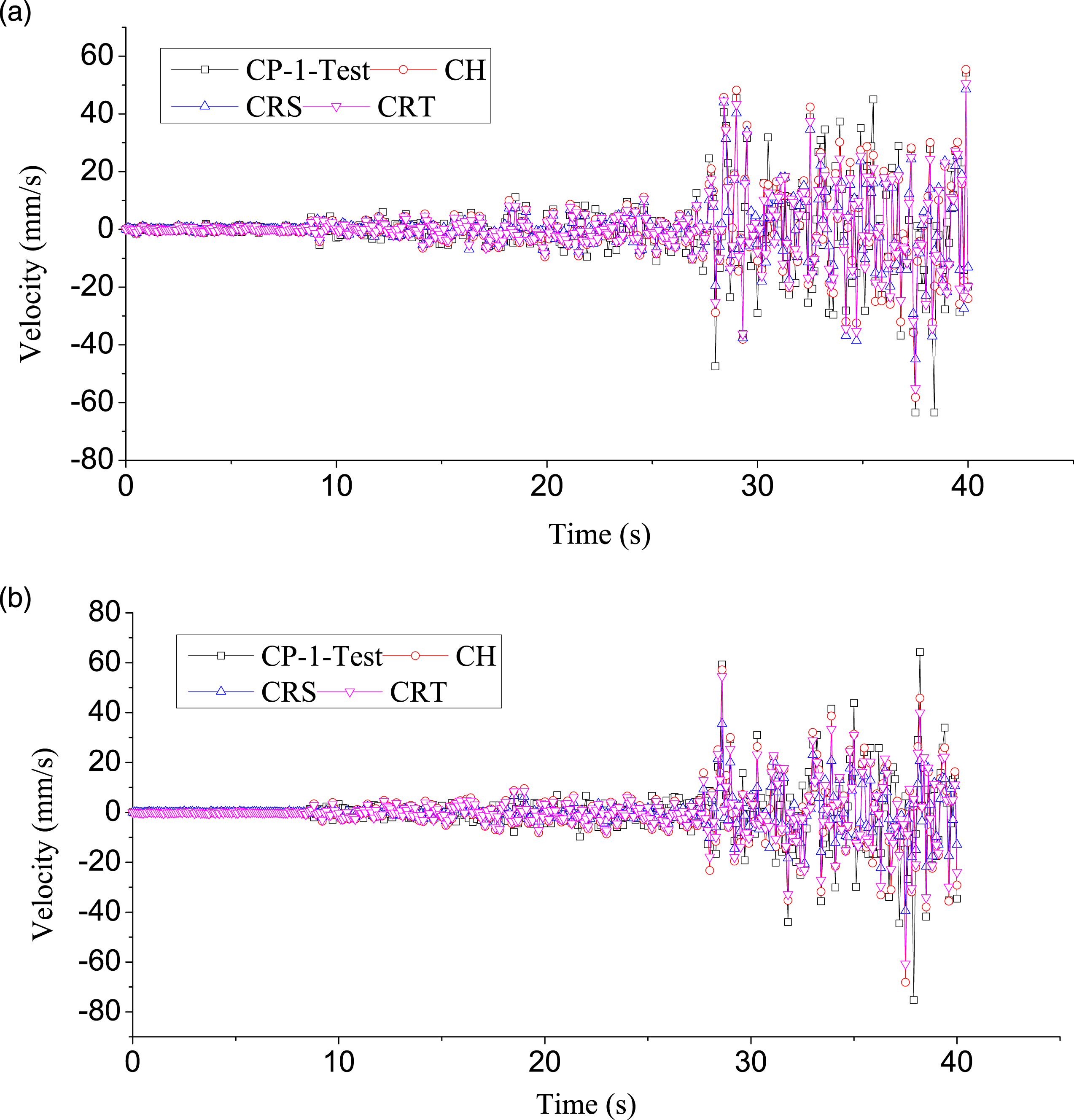
4. Conclusions
The objective of this study is to develop and calibrate a complex mode superposition method for nonproportionally damped linear systems, which is based on the hysteretic damping model. This method is the basis for the mode decomposition response spectrum method and can be used to calculate the seismic design forces of linear building structures with nonproportional damping.
The construction of a damping matrix based on the Rayleigh damping model does not exhibit uniqueness, which is significantly related to the choice of reasonable modes. Compared with the Rayleigh damping model, the damping matrix of hysteretic damping model is only related to the structural stiffness and the damping properties of materials and is irrelevant to the choice of modes.
The general solution of the corresponding homogeneous equation and special solution of the corresponding nonhomogeneous equation can be solved and superposed linearly. Then, a complex mode superposition method of the MDOF nonproportionally damped linear system based on a hysteretic damping model is realized. Compared with some common methods which are usually established based on the viscous damping model, the computational efficiency of the proposed method is higher. Besides, the proposed method is realized based on the assumption of relationship of external excitations, which is unconditionally stable.
Based on the proposed method, a user subroutine in ANSYS and MATLAB is developed to calculate vibration responses in time-domain dynamic analyses. This subroutine was verified by the comparisons of shaking table test results. The frequency response curves and vibration responses under random excitation show that the accuracy and efficiency of the proposed computational method are higher than those of the complex mode superposition method based on the Rayleigh damping model.
Footnotes
Declaration of conflicting interests
The authors declared no potential conflicts of interest with respect to the research, authorship, and/or publication of this article.
Funding
The authors disclosed receipt of the following financial support for the research, authorship, and/or publication of this article: This work was partially supported by the National Natural Science Foundation of China (Grant No. 51878100) and partially supported by the Graduate Research and Innovation Foundation of Chongqing, China (Grant No. CYB18036).
