
Abstract
This article focused on further investigation of passive vibration damping of a cantilever plate using carbon nanotube/epoxy nanocomposite. A damping ratio depends on many factors, for example carbon nanotube content, type of carbon nanotubes, and frequency, so the epoxy composite reinforced with 0.2 wt. % multi-wall carbon nanotubes has been used with structural damping. Dynamic analysis for an aluminum cantilever plate has been studied to determine the effect of the epoxy nanocomposite material on the plate vibration. The main goal of the study was to minimize the frequency response function amplitude and shift the resonant frequency of the plate as high as possible, especially for the fundamental frequency. An finite element model exhibited an increase in the resonant frequency by 10.6% and 1.2% in addition to a reduction in the frequency response function amplitude by 79.5% and 43.26% at the first and second bending modes, respectively, when using 0.2 wt. % multi-wall carbon nanotubes/epoxy circular patches at an optimal position compared with the bare plate. In case of using a stiffener below the plate, the results exposed an increase in resonant frequency by 154.6% and 181.7%, whereas the frequency response function amplitude showed reduction by 95.9% and 98.2% at the first and second bending modes, respectively, when using three stiffeners of multi-wall carbon nanotubes/epoxy nanocomposite with the same mass of circular patches compared also with the bare plate.
1. Introduction
Lately, a significant mechanical property called structural damping using nanocomposite materials had received great attention from numerous scientists. From the application perspective, structural vibration damping is mainly considered as an important parameter for the health monitoring of structures. Recently, many industries are directly exposed to the hazard of vibrations, such as numerous military components, vehicle industry, aerospace equipment, and astronautics industries. Microcrack propagation in these structures spreads quickly because of fatigue stress brought by vibrations, leading the structures to total collapse. carbon nanotubes (CNTs) can be valuable in overcoming these issues because they improved the structural damping and prevented the spreading of microcracks by connecting between the nanotubes. Currently, fibers of carbon and graphite were used to enhance the structures in health monitoring. CNTs are expected to be used in the health of structures once they can be created with mass production at a low cost. Koratkar et al. (2005) investigated around 200% improvement in the damping ratio by using epoxy composite reinforced with multi-wall carbon nanotubes (MWCNTs). Comparative examinations directed by Rajoria and Jalili (2005) demonstrated an improvement of about 140% in the damping proportion of single-wall carbon nanotubes/epoxy composite in comparison with pristine epoxy composites. Du et al. (2004) have displayed the damping characteristics of CNT composites using the stick–slip concept.
There are several kinds of vibration damping methods in space structure applications: passive, active, and hybrid vibration control. In the case of passive damping techniques, the vibration energy was dissipated by using damping elements without feedback capability, whereas the active damping methods depended on actuating elements such as a piezoelectric actuator to produce a force equal in magnitude with the excitation force that caused the vibration but in the opposite direction. The hybrid damping techniques consist of combined elements from the two previous methods.
The passive vibration damping system is the most reasonable for space application because of its simplicity in suppressing a wide frequency range of mechanical vibrations with no power required. In passive damping systems, the damping element weight is a critical design parameter, especially with space application, so the designer’s main target is to get maximum vibration damping with minimum cost and weight (Ansari, 2013). Gürgen and Sofuoğlu (2019) studied the vibrational properties of carbon fiber–reinforced polymer tube structure filled with a natural shear thickening fluid (STF); the results of this structure viewed a significant improvement to the natural frequency and increased its damping ratio, which made it reasonable to use in unmanned aerial vehicles such as drones. Gürgen and Sofuoğlu (2020) modified the conventional sandwich structure by integrating the STF which previewed significant enhancement in the structure vibration attenuation properties, but the damping behavior was decreased because of the temperature increase. To minimize the weight as possible, the structure was treated by damping patches or using stiffeners. Viscoelastic materials (VEMs) could be considered as effective materials in different vibration damping techniques, where VEMs, particularly rubbers, had the highest constant damping ratio among all damping materials. The VEM properties exposed strong change with the temperature and frequency change, which should be taken into consideration for many vibration damping applications. A VEM layer could be categorized into free-layer damping (FLD), constrained-layer damping (CLD), and active CLD. In FLD, one single VEM is bonded, and in case of CLD, one additional thin stiff layer is bonded on the top of the viscoelastic layer to increase the damping efficiency
The cantilever plate’s geometry and shape such as size, weight, and material depended on the type of the application. The airplane wing, satellite solar array (SA) panels, and other components can be considered common applications that used cantilever plates in the design of its components. Such plates are presented to various dynamic loads in various applications. This load existing on a plate causes it to vibrate at its natural frequencies. The vibration analysis of a cantilever plate decides the dynamic noise and stresses. One of the most significant flexible sections of the satellite secondary structure was the SA structure. SA’s main function was to provide and hold the required area for solar cells which were responsible for producing the necessary electricity for satellite subsystem activity, keeping up their stability, integrity through launching, and operation conditions (Safak, 2013). SA was exposed to many vibration sources during its operation, such as “solar array deployment, solar snap load, fuel sloshing of propulsion system tank, maneuvering of satellite, and other subsystem vibration” (Havaldar et al., 2012). Moreover, SA had a low stiffness and damping ratio, so any excitation loads could cause an increase in vibration amplitude and settling time. Mechanical structure vibration at low frequencies is a challenging problem, particularly for light and flexible structures such as satellite SA (Tatavolu and Panchumarthy, 2013).
This article focused on further investigation of passive vibration damping of the cantilever plate which used CNTs/epoxy nanocomposite materials as damping materials, instead of using conventional materials such as aluminum. The damping ratio of a nanocomposite depended on many factors, for example CNT content, type of CNTs, and frequency, so the epoxy composite reinforced with 0.2 wt. % COOH-MWCNTs had been used after structural damping because of their high stiffness and low weight. The MWCNTs were functionalized with carboxylic groups (-COOH) to improve its dispersibility and interfacial bonding with epoxy resin as seen in our previous work (Alawy et al., 2019). This study aimed to use nanocomposite materials to decrease the undesirable vibration and decrease the stresses created in various applications in which plates are basic parts as discussed in the Introduction section; the rest of this article is sorted out as follows. Section 2 comprises the numerical calculation of the fundamental frequency of the rectangular plate and determination of the damping ratio. Section 3 highlights the numerical determination of the natural frequency and frequency response function (FRF) of a rectangular plate using ANSYS finite element (FE) software. Section 4 contains a summary of the work.
2. Theoretical dynamic analysis of rectangular plate
In this segment, a survey on a cantilever plate natural frequency derivation and a determination of plate natural frequencies (first/second mode of vibration) using energy methods are conducted. A cantilever plate with a rectangular cross-sectional area (a × b), aspect ratio, and thickness (t) is generally bounded with one edge fixed and the other three edges free as shown in Figure 1. Schematic drawing of the processing technique.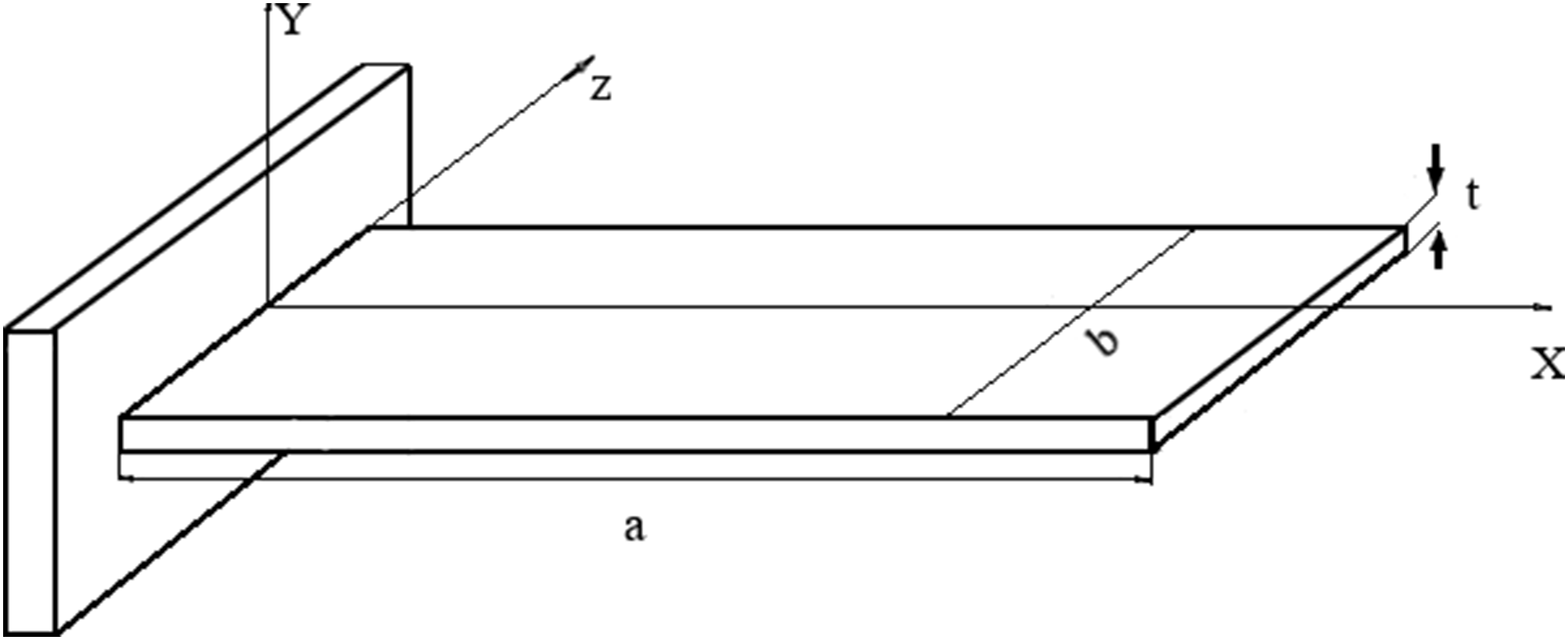
Basically, there are two possible methodologies in writing the governing differential equations of motion. We may either apply the d’Alembert’s dynamic equilibrium principle or use a principle of work formulation dependent on the preservation of energy

2.1. 1st mode shape of a rectangular plate
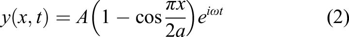
The lateral deflection equation has to satisfy the boundary condition for the (clamped–free–free–free) plate; from the assumption of a sinusoidal time response for free vibration, the lateral deflection according to Leissa (1969, 1973) can be defined as Schematic drawing of the first bending mode shape.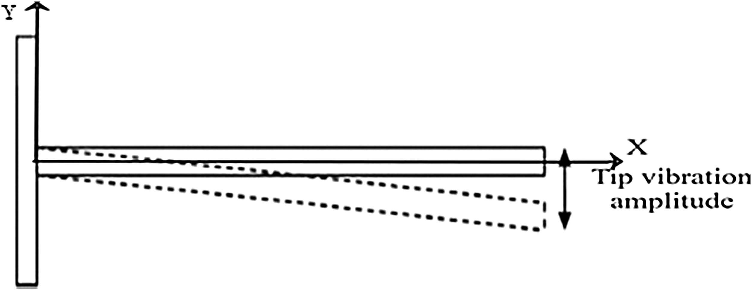
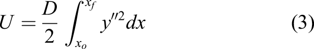
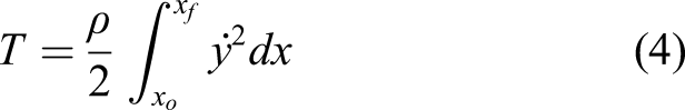
By doing the latter integration from x
o
= 0 to x
f
= a, the maximum strain energy and maximum kinetic energy were obtained, and then substituting into equation (1), the following relation can be reached
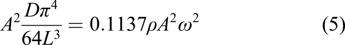
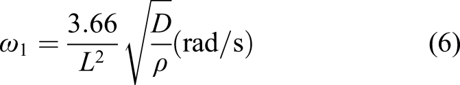
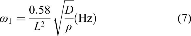
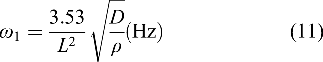
Consequently, the plate’s first natural frequency will be
2.2. 2nd mode shape of a rectangular plate
An expression for lateral deflection y(x, t) of a cantilever (Figure 3) plate is assumed to verify boundary and initial conditions in the form according to (Leissa, 1969) Schematic drawing of the first bending mode shape.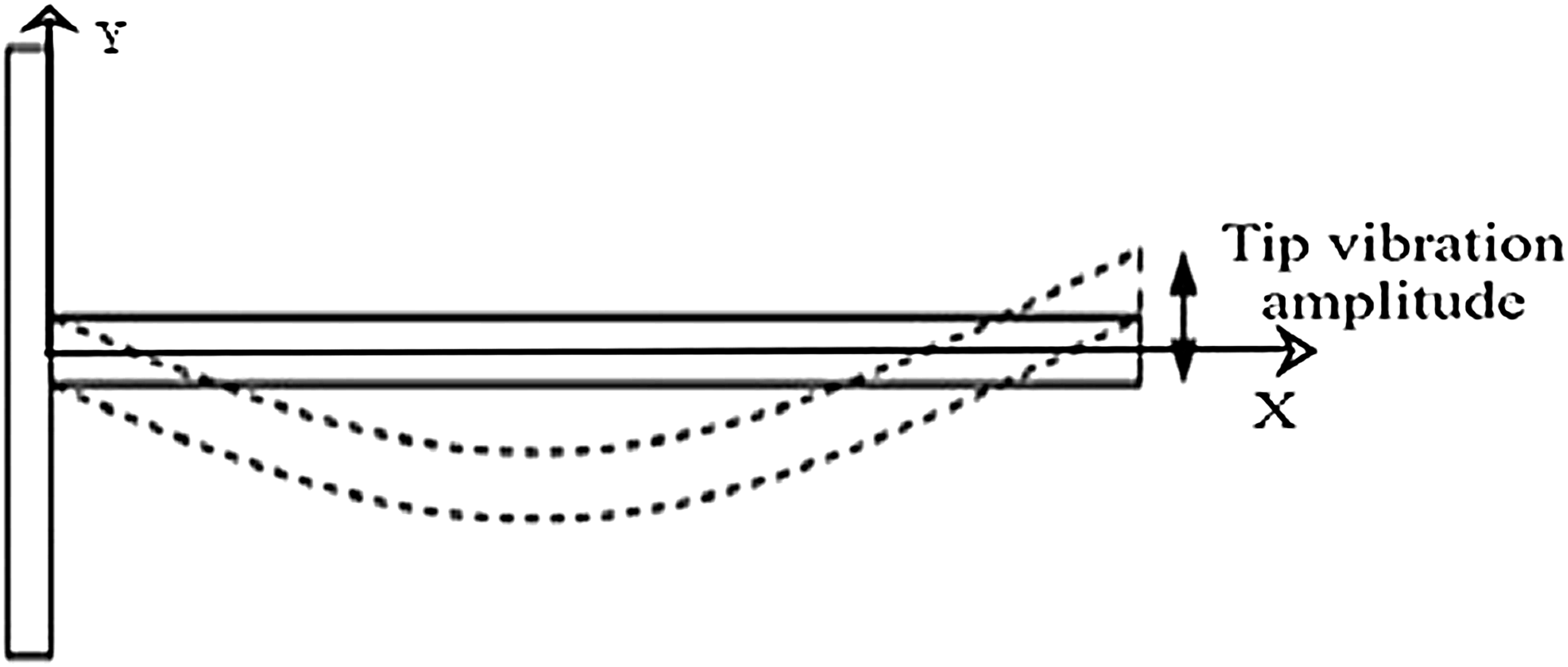
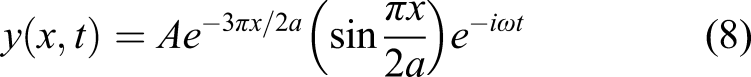
After performing the previous integrations corresponding to the lateral deflection of the second mode shape and getting the maximum strain energy and maximum kinetic energy and then substituting into equation (1), the following relation can be reached
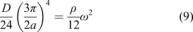
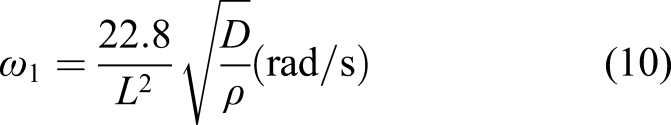
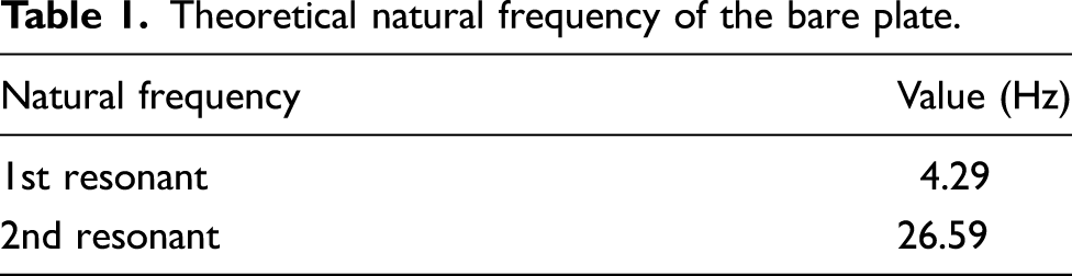
Hence, the plate’s second mode natural frequency is obtained in the form
Theoretical natural frequency of the bare plate.
3. Numerical modeling analysis of rectangular plate
The finite element model process was developed by using the “Engineering Data section” in ANSYS workbench package version R16.0.
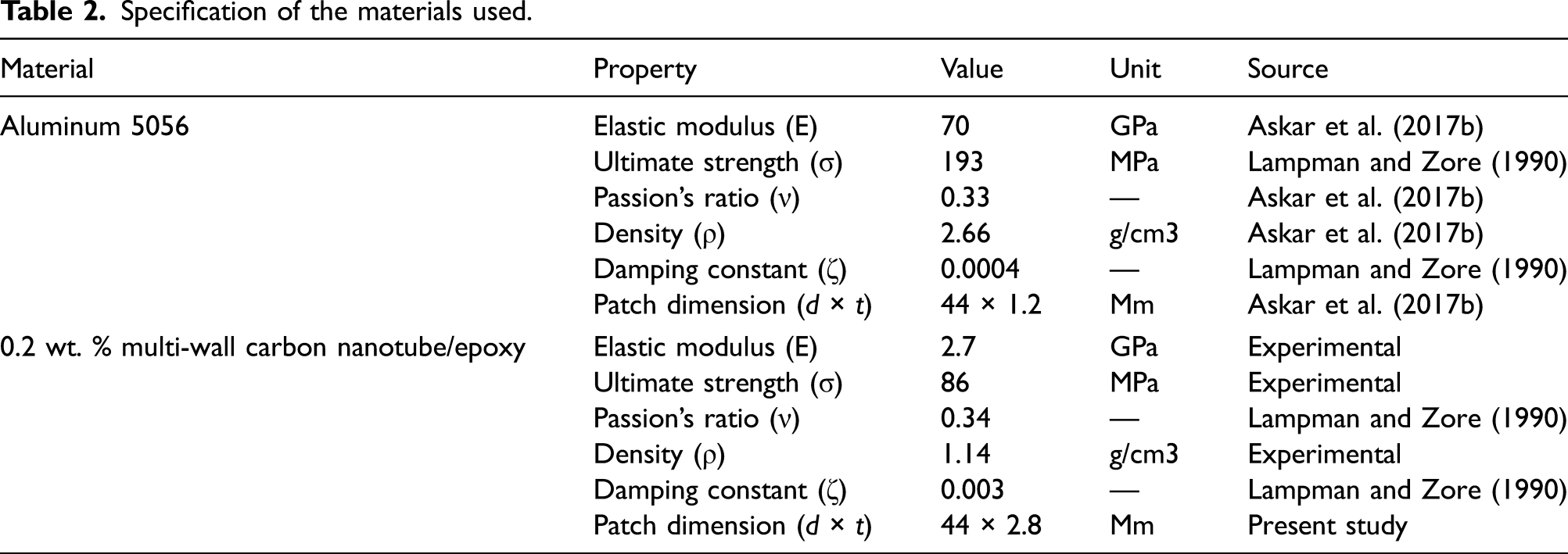
3.1. Mechanical properties of finite element model material
Specification of the materials used.
3.2. Finite element procedures
After conducting a convergence study through the ANSYS model using analysis of mesh sensitivity, the number of the elements was decided corresponding to the plate amplitude in a static analysis at different mesh sizes. The total number of elements and nodes used for the bare plate finite element model (FEM) with the final meshing process equals 4036 elements and 28962 nodes with a 5-mm mesh element size. The static analysis of the plate tip displacement applied to the model produced as a result of the gravitational acceleration and circular patch that represented the accelerometer which had mass equaling about 5% of the plate mass at the free end. The modal analysis had previewed the plate’s first six natural frequencies First six mode shapes of the plate using finite element.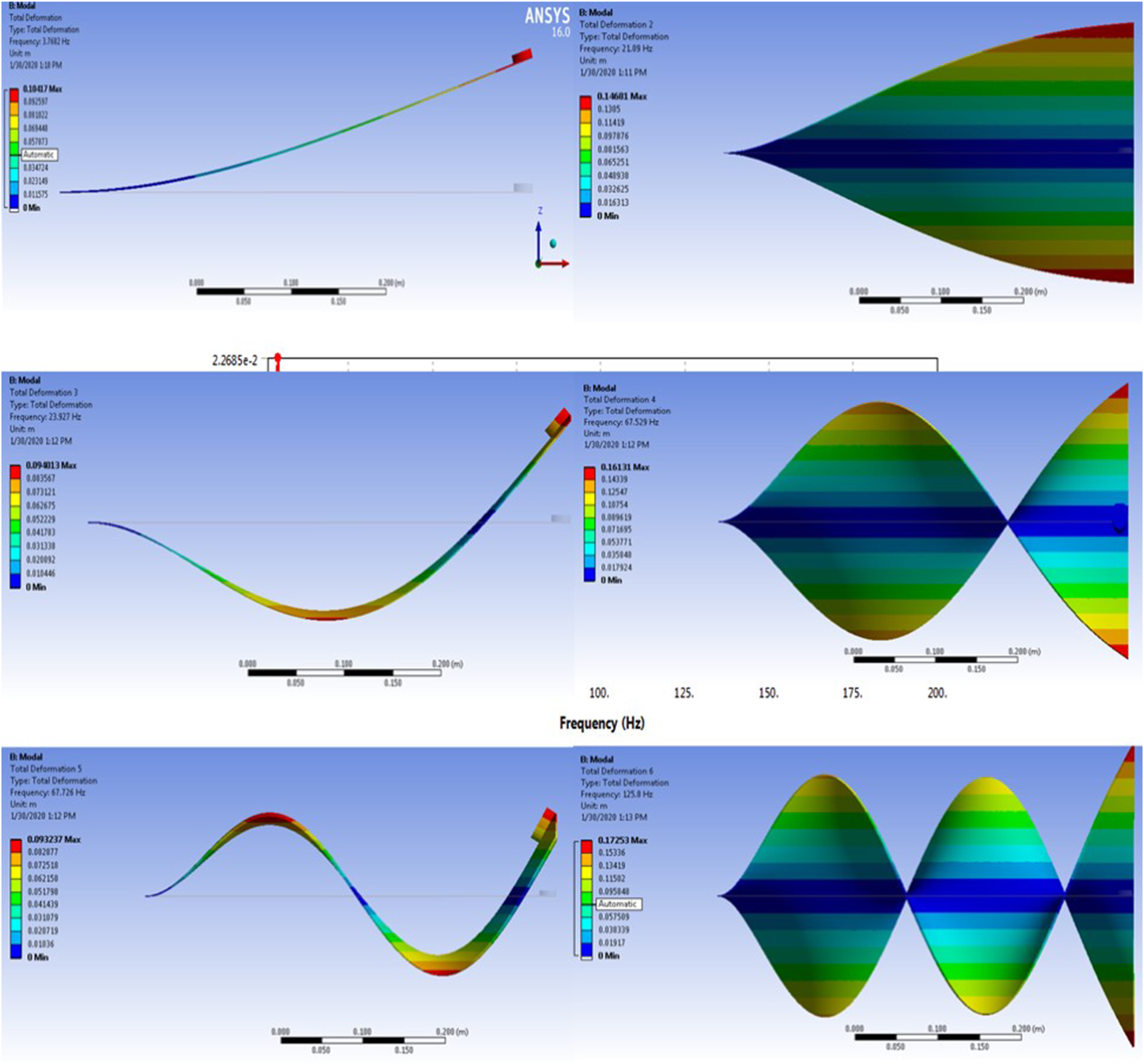
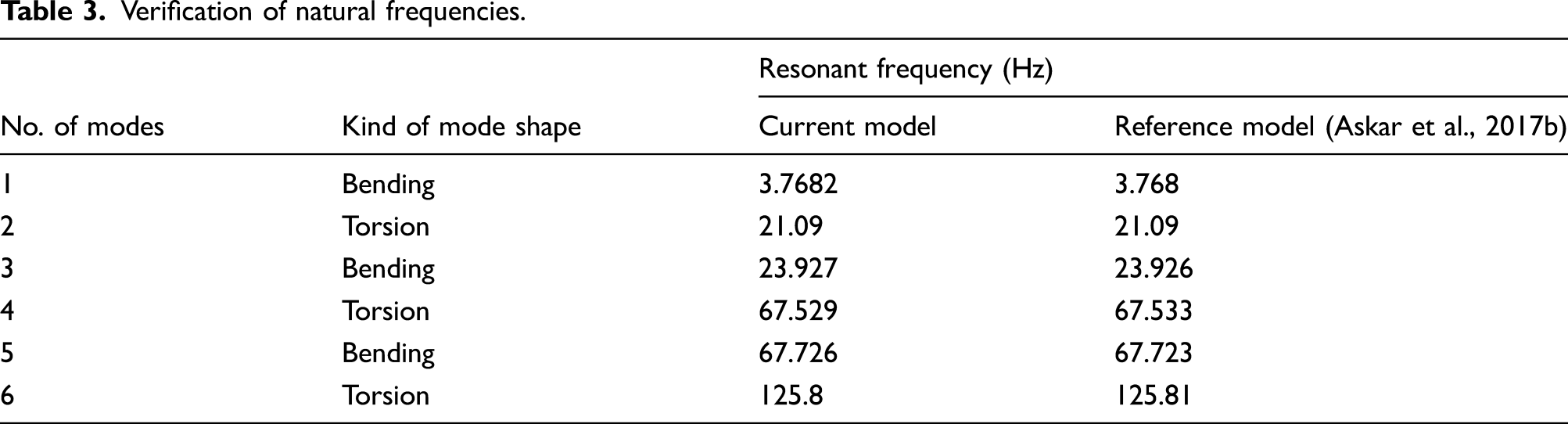
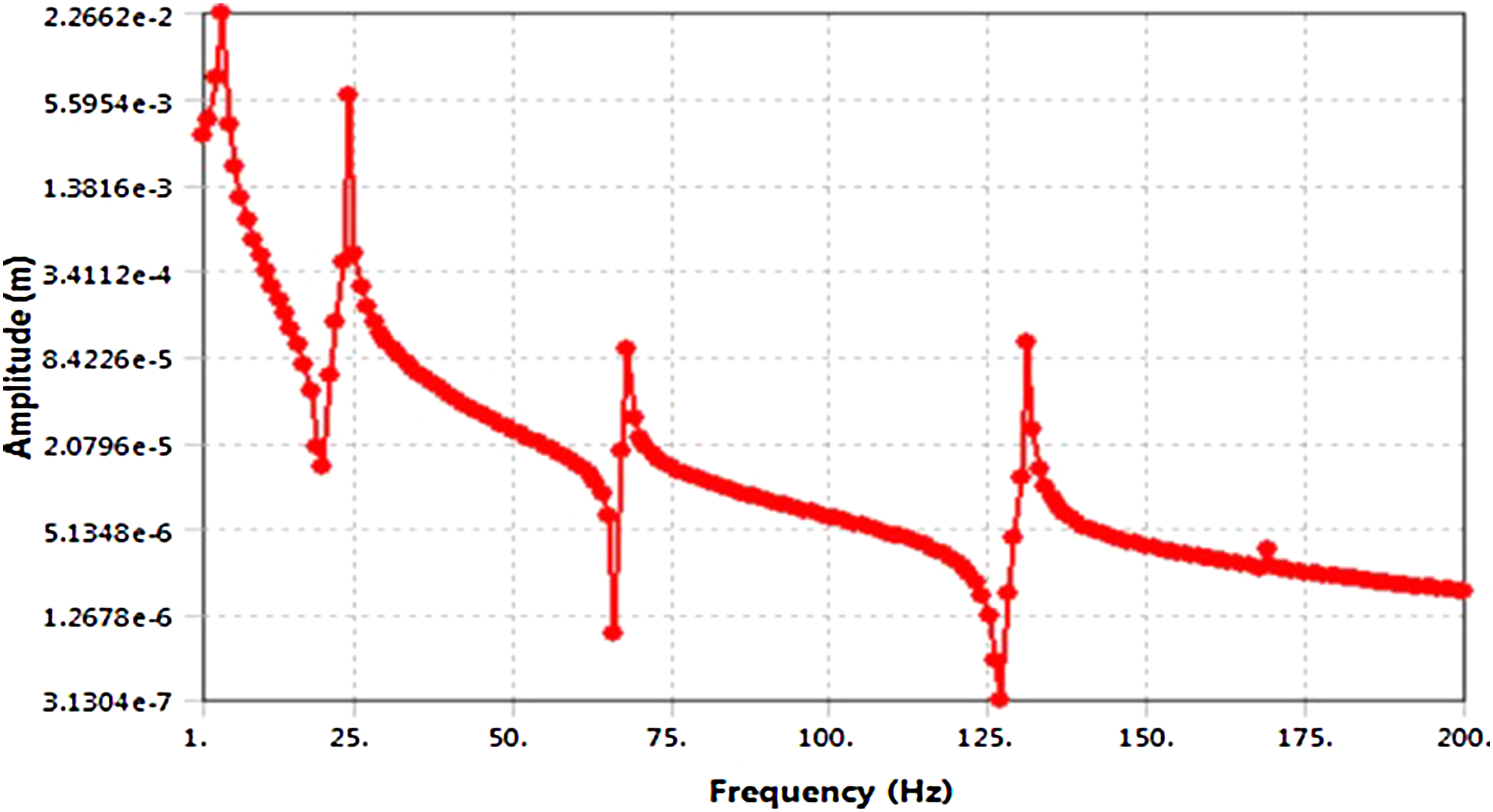
3.3. Finite element modeling verification
In this partition, a thin aluminum rectangular plate can be expressed as the satellite SA as studied previously experimentally and theoretically in reference Askar et al. (2017a, 2017b). The first verification step was achieved by using the same plate dimension by adding the same value and distribution of the static load obtained from the reference taking into consideration the effect of the weight due to gravitational acceleration (g = 9.81 m/s2) and accelerometer weight which simulated with a circular patch at the free end. The comparison between the resonant frequencies of the numerical simulation work results and the results in the reference are shown in Table 3, which can be considered the second verified step. The third verification step is carried out by conducting a comparison between the reference FRF and the FRF of the current plate numerically at different resonant frequencies as shown in Figures 5 and 6, respectively. The results are in good agreement without any significant differences. Verification of natural frequencies. Frequency response function of the bare plate according to the reference. Regenerating frequency response function for the bare plate.
3.4. Parametric study
3.4.1. Plate with circular patch damping
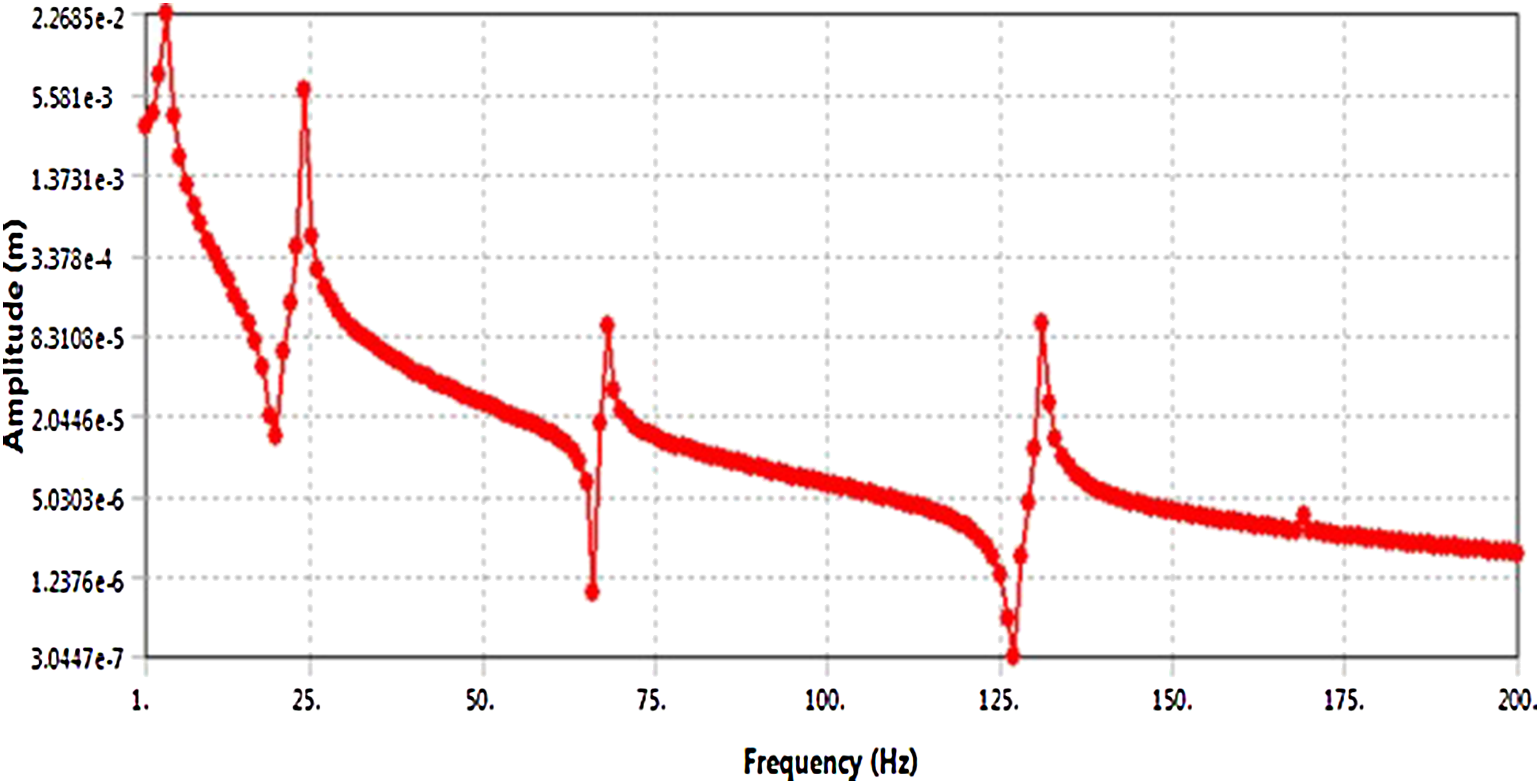
The comparison between the resonant frequencies and the FRF of the numerical simulation results was shown in the previous section which had good agreement between the two FE models. The main goal of the study was to minimize the FRF amplitude and shift the resonant frequency of the plate as high as possible, especially for the fundamental frequency. The circular patch geometry and its position on the plate had been determined with the aid of ANSYS direct optimization module (Askar et al., 2017b) as shown in Figure 7. Optimal position of the circular patches.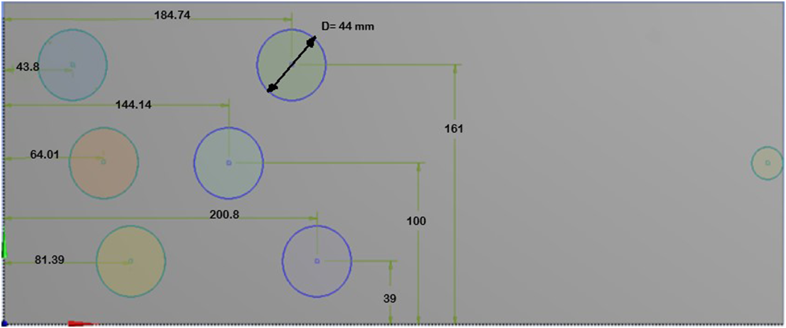
Plate’s first six resonant frequencies with circular patches.
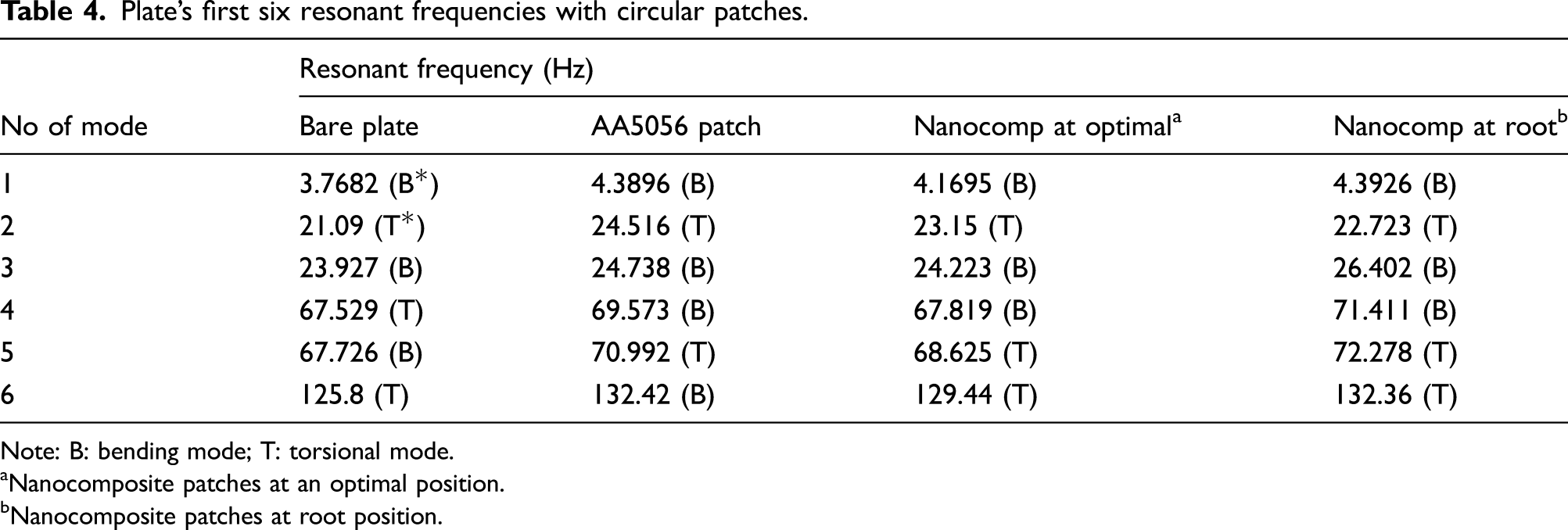
Note: B: bending mode; T: torsional mode.
aNanocomposite patches at an optimal position.
bNanocomposite patches at root position.
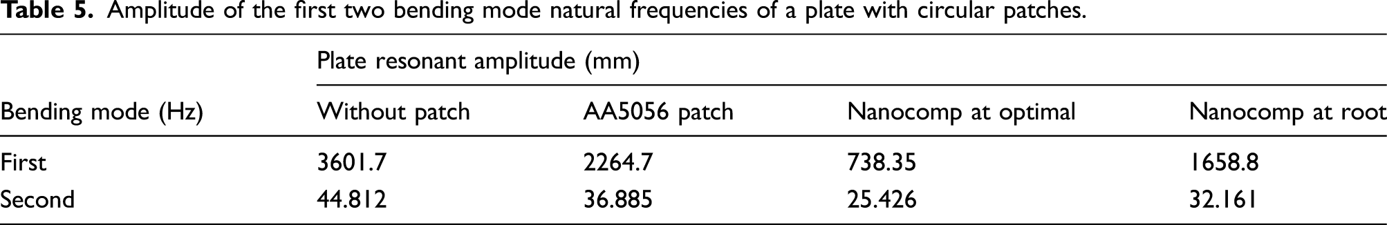
Amplitude of the first two bending mode natural frequencies of a plate with circular patches.
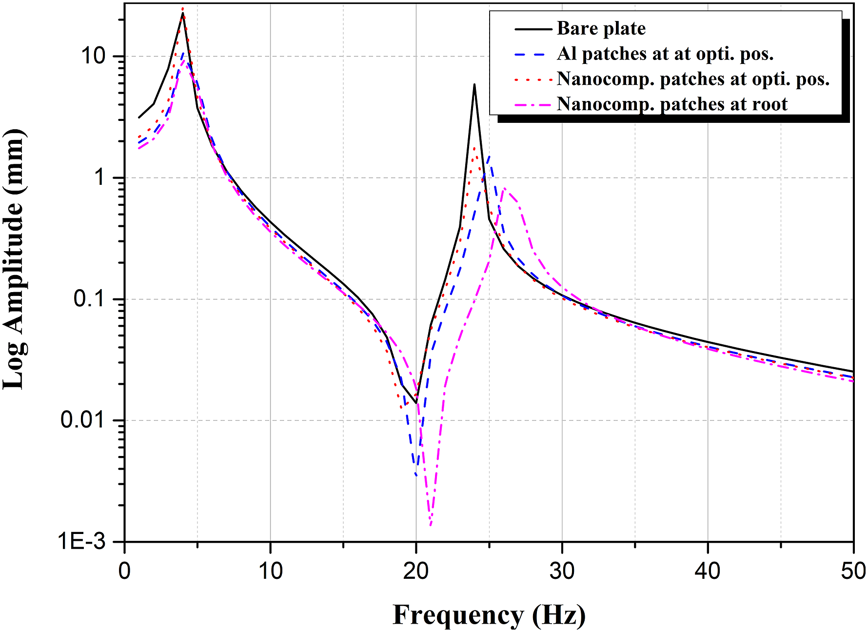
Frequency response function comparison between aluminum and nanocomposite circular patches.
3.4.2. Plate with stiffener damping
Stiffener arrangement configuration setups on plate.
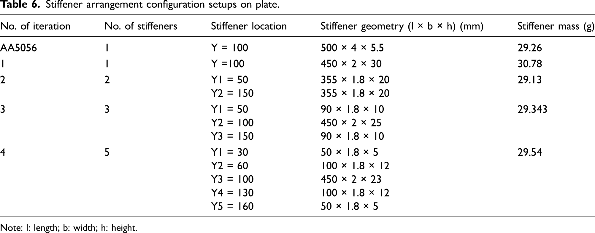
Note: l: length; b: width; h: height.
Plate’s first six resonant frequencies with stiffeners.
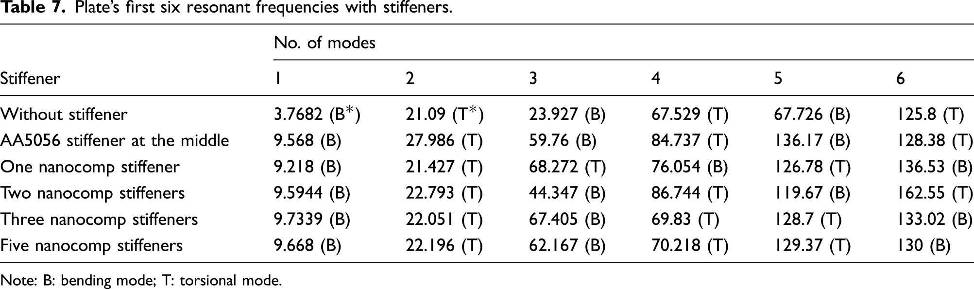
Note: B: bending mode; T: torsional mode.
Amplitude of the first two bending natural frequencies of a plate with stiffeners.

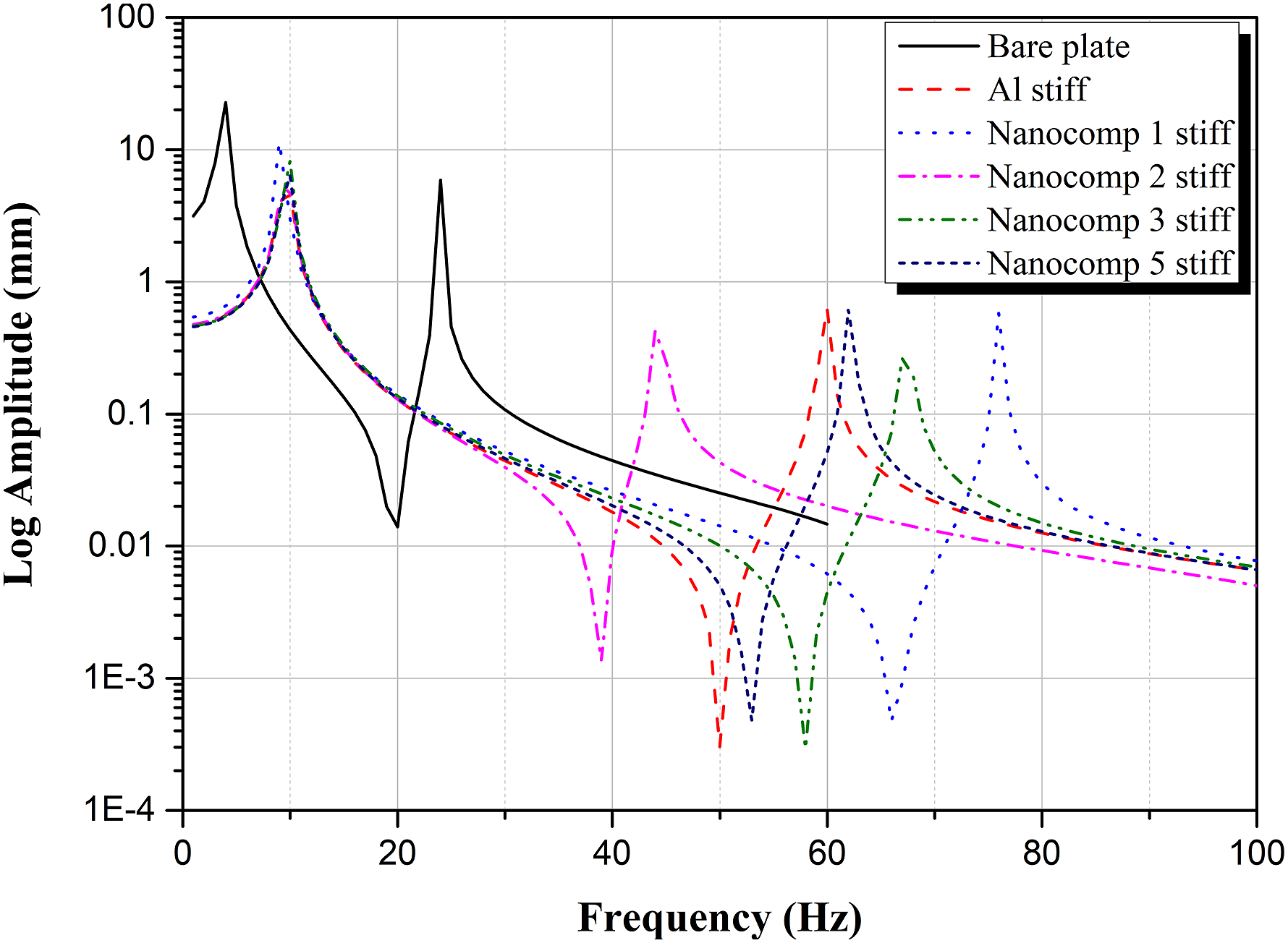
Frequency response function comparison between aluminum and nanocomposite stiffeners.
4. Conclusion
Among different techniques of vibration attenuation, the passive vibration attenuation was considered from the most important and necessary approaches used in space structure applications because of its simplicity, and no power or maintenance was required. In case of using damping patches by changing aluminum materials with MWCNTs/epoxy composite at the optimal position leads to the following:
The resonant frequency is decreased by 5% and 2% for the first and second bending modes, respectively, but the plate’s amplitude FRF is decreased by 67% and 31% for the first and second bending modes, respectively, in comparison with aluminum patches at the same position. The results confirmed the effect of using nanocomposite materials as patches in the enhancement of the vibration attenuation of the plate. 2. In another parametric study, the passive vibration attenuation, using rectangular cross-sectional area stiffeners by also changing the aluminum materials with MWCNTs/epoxy composite with different geometry and number of stiffeners, but conserving the same stiffener mass, leads to the following:
From the result data, the three stiffeners from the MWCNTs/epoxy composite materials achieved maximum vibration attenuation of the plate, where the resonant frequency is increased by 2% and 13% for the first and second bending modes, respectively, and the plate amplitude FRF is decreased by 74% and 87% for the first and second bending modes, respectively, in comparison with one aluminum stiffener at the middle of the plate with the same mass for both cases as mentioned previously. These results also confirmed the effect of using nanocomposite materials as patches in enhancement of the vibration attenuation of the plate.
Footnotes
Declaration of conflicting interests
The author(s) declared no potential conflicts of interest with respect to the research, authorship, and/or publication of this article.
Funding
The author(s) received no financial support for the research, authorship, and/or publication of this article.