The inerter-based isolation system, which comprises an inerter, a dashpot, and a spring, has been shown to be effective for improving the dynamic performance of isolated structures. However, the underlying theoretical basis of its vibration control mechanism has not been studied for superstructures with inerter-based isolation system; in particular, the functionality of the inerter has not been explicitly demonstrated. In this study, the displacement mitigation mechanism is established by deriving a fundamental equation, designated as the displacement demand equation. The mechanism is explained by clarifying the functionality of the inerter-based isolation system to determine the theoretical relationship between the displacements of the superstructure and isolation layer. A nominal displacement demand ratio is defined to evaluate the overall displacement demand of the structure–inerter-based isolation system, by considering the contribution of the inerter-based isolation system. Following the displacement mitigation mechanism, design strategies are developed for inerter-based isolation system, where the isolation frequency ratio can be directly determined once the target displacement performance of the entire structure–inerter-based isolation system is prespecified. In addition, the inertance-mass ratio and damping ratio of the inerter-based isolation system can be obtained according to the target demand of the superstructure displacement. Finally, a series of examples are used to verify the derived displacement demand equation and proposed design strategy. In this study, the displacement mitigation mechanism yields an effective design method that is suitable for the inerter-based isolation system and has a clear physical basis. Through the proposed displacement mitigation–oriented optimal strategy, a target displacement demand for a structure can be satisfied directly, which also provides an optimized displacement performance for the isolation layer. The displacement mitigation mechanism and equation are practical for the simplification of the design procedure and help to reveal the advantageous features of the inerter-based isolation system.
In terms of the isolation system, the introduction of inerters can significantly increase the apparent mass of the system by means of rotational mass with motion transformers (Eliseev, 1978; Rivin, 2003). Nakaminami et al. (2012) analyzed the application and effectiveness of a force-restricted rotational viscous mass damper for a base-isolated multistory structure. Zhao et al. (2019c) developed a friction pendulum inerter system to enhance the performance of an isolated structure. Takewaki et al. (2012) analyzed the fundamental mechanism of an isolation system incorporating an inerter for earthquake protection of buildings. De Domenico and Ricciardi (2018) numerically optimized a system with a tuned mass damper inerter installed in the isolation layer of a structure. Sun et al. (2019) proposed an optimal design method for an IIS, where the optimization equation was derived by assuming the superstructure as an undamped single-degree-of-freedom (SDOF) model for simplification.
As summarized above, the numerical and analytical solutions for a simplified isolated structure with an IIS have been analyzed by partially optimizing the performance of the superstructure or the isolation layer. However, there remains a need to develop a direct quantification of overall displacement performance of the structure–IIS system to develop a theoretical understanding of the essential link between key parameters of IIS and the dynamic response of each subsystem in the isolated structure.
In this study, a displacement mitigation mechanism is established by deriving a displacement demand equation based on the analytical stochastic response of the structure–IIS system. This equation explicitly contains the basic relationship between the structural displacement and IIS parameters, which further provides a rational and compact means for quantifying the response of the entire structure–IIS system. A corresponding optimal design strategy is developed that implements the displacement demand equation and exploits a demand-oriented philosophy. Finally, numerical examples are presented to validate the derived displacement demand equation and design criterion.
2. Displacement mitigation mechanism of structure–IIS system
2.1. Mechanical model of structure–IIS system
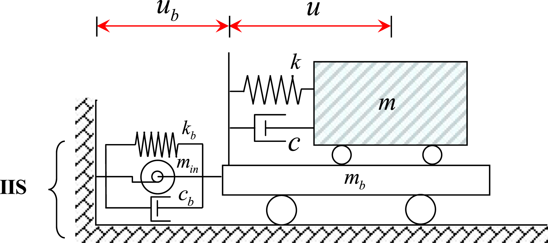
The considered IIS in this study is formed by inserting an inerter into a base isolator in a parallel layout (Figure 1), which has been previously proposed and investigated as an effective improved isolation system. The conventional base isolator is modeled by a base spring and dashpot that are connected in parallel. Consider a viscously damped structure isolated by an IIS (Figure 1) that can be represented by a 2-DOF system linked to the ground by an IIS. The superstructure is an SDOF structure defined by mass , stiffness , and damping , whereas the isolation layer is defined by a base mass with a connected IIS. The deformation of the IIS is represented by and equal to the displacement of the isolation layer, , relative to the ground. The control force of the IIS can be expressed as
where and signify the velocity and acceleration responses, respectively. This mechanical system can be described in a nondimensional form, whose parameters are presented in Table 1.
Mechanical model of SDOF structure and base isolation system with IIS. Note: SDOF: single degree of freedom; IIS: inerter-based isolation system.
Mechanical parameters of the structure–inerter-based isolation system system.
Parameter
Definition
Description
Structural parameters
Structural circular frequency
Inherent damping ratio
Mass ratio of isolation layer
IIS
Isolator
Frequency ratio
Isolator damping ratio
Inerter
Inertance-mass ratio
Note: IIS: inerter-based isolation system.
2.2. Stochastic vibration analysis and closed-form solutions
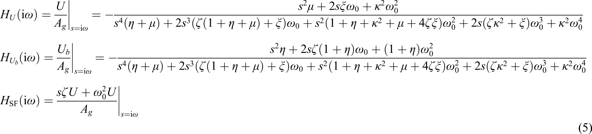
The governing equations of motion for the structure–IIS system subject to the horizontal excitation can be established as
where is the deformation of the superstructure (Figure 1), and is the normalized force of the IIS, defined as
Through a Laplace transformation, the differential equations in equation (2) can be converted into the following algebraic form
Here, are the Laplace transformation forms of , respectively and , where is the imaginary unit and is the circular frequency of the excitation. By solving equation (4), transfer functions with respect to , and the structural shear force can be developed
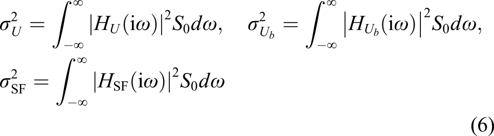
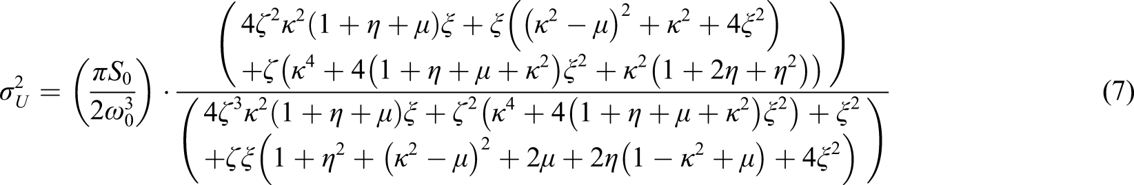
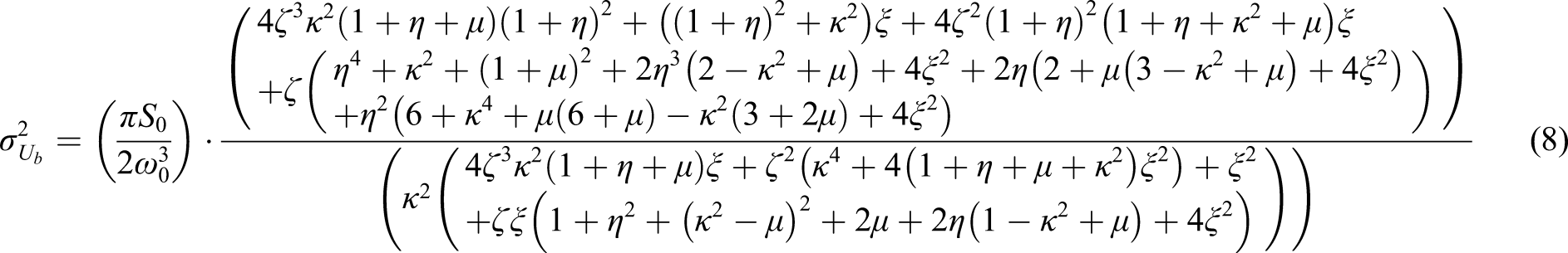
Under a white noise with an input-power spectra amplitude , the mean-square structural displacement response , isolation layer displacement , and shear force are obtained by the random vibration theory as
By integrating equation (6) (Crandall and Mark, 1963), are converted into the closed-form expressions
2.3. Displacement demand equation and mechanism
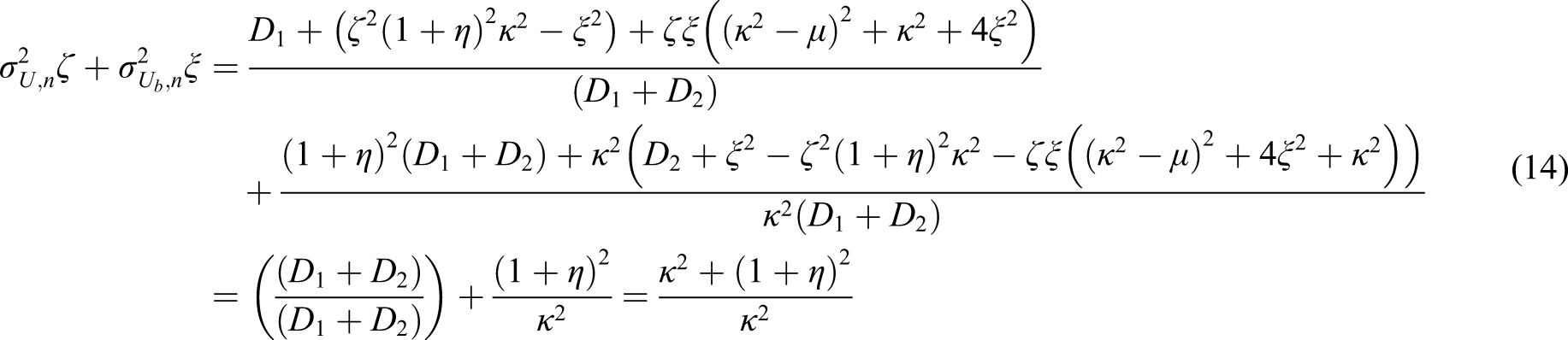
Based on the analytical stochastic response solutions above, a closed-form equation is derived, designated as the displacement demand equation, to explicitly investigate the theoretical displacement demand of the entire structure–IIS system. Through multiplication by , the mean-square responses in equations (7) and (8) can be reexpressed as
Substituting equations (7) and (8) into (10) and then multiplying by , respectively, the following expressions are obtained
where are expressed as
Adding in equation (11) to in equation (12) yields
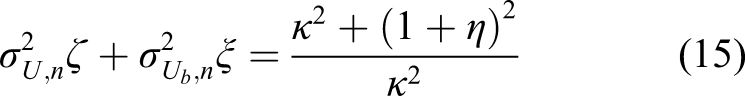
which is simplified as
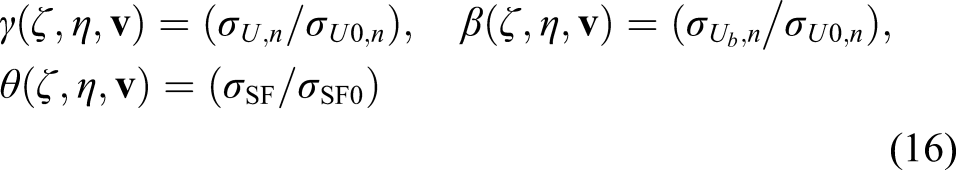
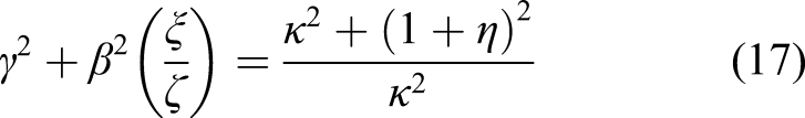
The displacement demand ratio of the superstructure , isolation layer displacement demand ratio , and shear force response ratio are defined to evaluate the structure–IIS system
where is the parameter vector of the IIS and . The subscript “0” denotes the uncontrolled SDOF structure (Pan and Zhang, 2018). Substituting equation (16) into (15), a closed-form equation for the structure–IIS can be obtained as
which is designated as the displacement demand equation in this study. The portions of the displacement distributed to the superstructure and the isolation layer are evaluated as and , respectively, whereas the sum of the two comprises the displacement demand of the entire structure–IIS system, that is
where is defined as the nominal displacement demand ratio. Note that isolation layer displacement is weighted by to reflect the energy dissipation cost of the IIS. With this special consideration, the developed optimal design of will not fall into a solution with a large damping ratio of the IIS.
The displacement mitigation mechanism refers to the quantified determination of the overall displacement demand in terms of the IIS parameters including . For an isolated structure with given is negatively correlated with , which is logically consistent with the fact that a more rigid isolator can reduce the system displacement more effectively. In addition, a large is beneficial for decreasing the isolation layer displacement. This mechanism reveals the essential relationship between the displacement responses of the superstructure and isolation layer, while simultaneously reporting the basic control mechanism of the IIS for displacement control. From the perspective of multiobjective control, it is rational to consider the dynamic performances of the superstructure, , and isolation layer, , simultaneously. This, therefore, means that it is rational to take the displacement response of the entire structure–IIS system, , into consideration. Given a prespecified target displacement demand of the entire structure–IIS system, , equation (17) yields the value of the theoretically required isolation frequency ratio, , as
2.4. Parametric analysis
Once the isolation frequency ratio can be directly determined by , the other undetermined parameters of the IIS, , can be considered. To this end, a parametric analysis is conducted, where the factors primarily investigated are: (1) the proportion of the displacement of the superstructure, , (2) the proportion of the displacement of the isolation layer, , and (3) the measurements of the structural response levels, that is . For this investigation, unless it is explicitly stated otherwise, a widely used isolated structure with the following parameters is adopted: (De Domenico and Ricciardi, 2018).
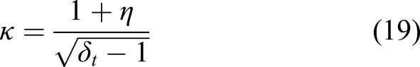
The variations in and are calculated according to closed-form equations (7), (8), and (16). Given , the variations in and are shown in Figures 2 and 3, respectively. As anticipated, the displacement performance of the superstructure improves ( decreases correspondingly) as decreases from 0.50 to 0.20, which is consistent with the fact that a lower stiffness isolator can provide a greater isolation effect and reduce the displacement of the superstructure more effectively.
Contour plots of of structure–inerter-based isolation system for (a) , (b) , and (c) .
Contour plots of of structure–inerter-based isolation system for . (a) , (b) , and (c) .
In Figure 2, the minimum value region of is represented by a blue-colored basin, in which the minimum is located in the parameter set of a small and a medium , which emphasizes the necessity of the inerter with a nonzero inertance for enhanced performance of an isolated structure. As increases, the displacement proportion distributed to the superstructure is marginally increased, while exhibiting an improved performance of the isolation layer. At the same time, the location of the minimum moves toward the upper right, indicating that greater and are desired. The contour lines in Figure 2 are similar to those in Figure 3. Comparing Figure 3 with 2, the color map is inverted and the location of the basin is inversely transferred into a single peak.
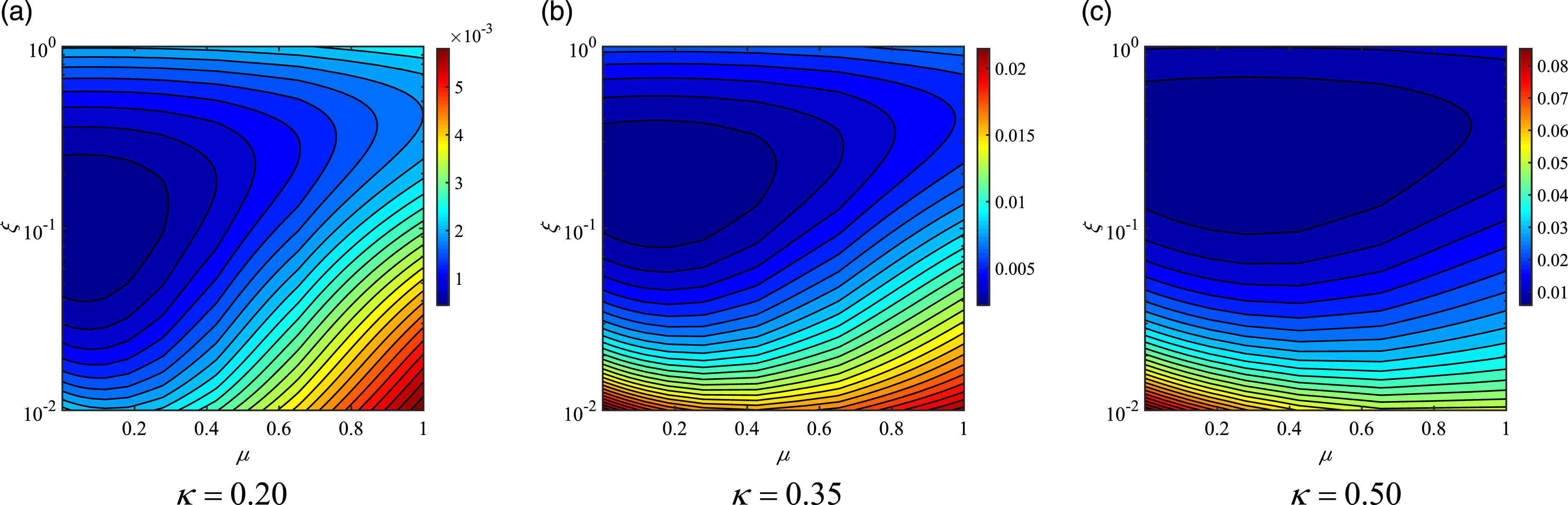
Inspired by the parametric analysis results, a rational strategy for parameter determination is required once is solved for using equation (19). For clarity, the results of , , and are plotted in contour curve form (see Figure 4). It can be concluded that the variation pattern and the values of and are approximately the same, which suggests that it is accurate and reasonable to use as a substitute for when determining IIS parameters.
Contour plots of , , and of structure–inerter-based isolation system for .
While the displacement responses of each portion of the structure–IIS system can be analyzed individually, as shown in the left subfigures of Figure 4, the displacement response of the entire structure–IIS system should be evaluated together, as shown in the right subfigure of Figure 4. In this figure, and are represented by the white contour lines and color-filled contour map, respectively. Any of the points on the same white contour line have the same level of ; however, these points are located in a range of different color-filled areas (i.e. different ). For each specific level of target displacement demand ratio of the superstructure , there always exists a point that denotes the minimum possible given the constraint provided by . This point (highlighted by the white circle) can be treated as a rational optimal parameter set for the IIS given an optimization strategy that satisfies the prespecified at a minimum price of . By inspection of this point, the optimal implementation of an inerter should be able to decrease the displacements of the superstructure and isolation layer simultaneously, as opposed to a conventional isolation system in which decreases in the response of the superstructure are typically accompanied by increases in the response of the isolation system.
Another potential optimal design strategy with a given is marked by a yellow triangle, as shown in the right subfigure in Figure 4. Under this design condition, the displacement of the superstructure can be minimized, which guarantees that the results are equal to or smaller than the possible prespecified . As shown in Figure 4, this strategy can be pursued by an IIS with a lower damping ratio and comes with the tradeoff of relatively higher displacement response in the isolation layer compared with the case of the white circle.
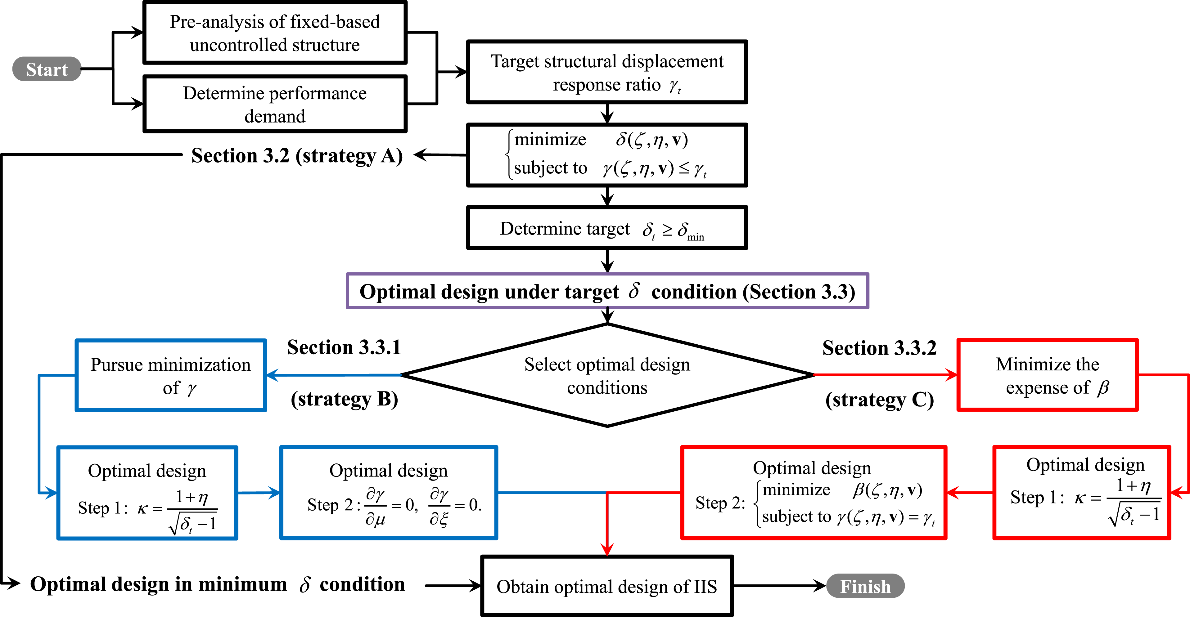
3.1. Concept overview of proposed design strategies
In this study, the determination of IIS parameters is suggested to be performed on the basis of the specified extent of displacement mitigation effect in terms of the entire structure–IIS system, which is a critical factor in the performance of the system (De Domenico and Ricciardi, 2018), and can be represented quantitatively by control targets and .
According to the displacement demand equation, (17), optimization given a specified can begin by obtaining from this equation. With this value of , one option is to minimize by optimizing the parameter set , denoted by the triangle in Figure 4. Another option, given a satisfactory , is to minimize , denoted by a circle in Figure 4. Both optimal locations will ensure that the structure achieves a prespecified , which also produce a satisfactory shear force performance given how well variations in track the variations in .
Formulated based on the above discussions, the design procedure of IIS is summarized in Figure 5, and the detailed optimal design equations are discussed in the following section. It is noted here that a multi-degree-of-freedom isolated structure can be simplified into a 2-DOF model considered in this study and optimized by the developed design strategies with satisfactory accuracy (Zhao et al., 2019a).
Parameter determination procedures of inerter-based isolation system based on displacement mitigation–oriented strategies.
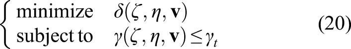
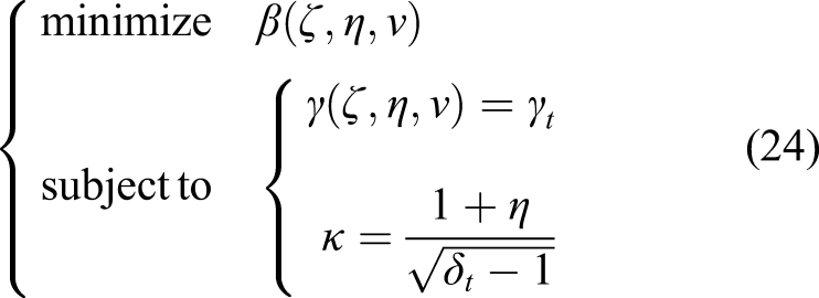
3.2. Extremum condition of minimum displacement demand
As stated in the optimal design strategy, the first step in the optimization is to determine the nominal displacement demand ratio . Under the constraint condition of ( represents ), the minimization of can be viewed as the lowest cost of displacement demand of the structure–IIS system, which is designated as design strategy-A in Figure 5. This minimization condition design is inspired by the displacement demand equation and expressed mathematically as
Solving this parameter design constraint, the minimum value of can be finally obtained, and the optimal parameters , , and are simultaneously obtained. The value of can be decided as per the performance demand and feasible range
Such that an optimal solution can be found.
3.3. Preset condition of target displacement demand
As stated in Section 2.3, can be easily obtained from equation (19) under the premise of a specified . Correspondingly, structural performances, including , , and , are presented in Figure 4, where two optimal parameter sets, marked by the circle and triangle, respectively, are acceptable.
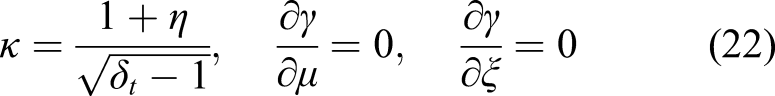
3.3.1. Minimization of
For the optimal solution via the minimization of , which is designated as strategy-B in Figure 5, the objective function can be interpreted as the partial derivatives of with respect to and set to zero. Therefore, the optimal problem of IIS can be expressed in a mathematical form as
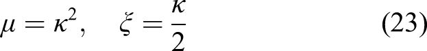
Considering that the damping ratio of the superstructure is typically small, the analytical expressions of and can be simplified as the functions of by assuming that
3.3.2. Minimization of
The other optimal solution considered seeks the minimum expense of to meet the upper limit of , which is designated as strategy-C in Figure 5. In this situation, a relatively large is beneficial to achieve a low response level of isolation layer displacement; on the other hand, this could inversely result in a large level of , that is the limit state where . The optimization problem of the IIS is correspondingly expressed as
4. Numerical examples
Using the proposed strategies for optimal IIS parameters, a number of examples of a typical structure De Domenico and Ricciardi (2018) isolated with an IIS are provided. The superstructure is characterized by the constant mass , natural period , and inherent damping ratio . The base mass is . The design conditions in Figure 5, which produce a minimum and target , are both applied to validate the effectiveness of the proposed displacement mitigation–oriented strategies and equation.
4.1. Case under minimum condition
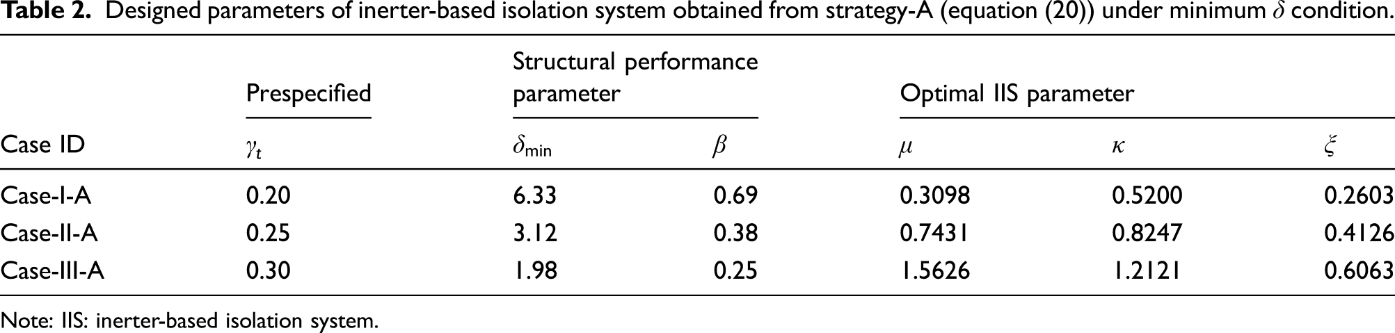
After an initial dynamic analysis of the original uncontrolled structure, the structural dynamic performance is to be improved by the IIS, where is assumed as 0.20 (Case-I), 0.25 (Case-II), and 0.30 (Case-III) as examples (corresponding to reductions of 80%, 75%, and 70% of the superstructure displacement compared with the uncontrolled structure, respectively).
Given the specified values of in each case, the IIS parameters can be obtained numerically from equation (20) by following the procedure in Figure 5. By inspection of the optimal results presented in Table 2, the IIS parameter sets featuring low values of , , and are beneficial for decreasing the superstructure displacement. As the performance demand on the superstructure increases ( decreases), lower values of (a more flexible isolator), (corresponding to the damping coefficient), and (to evaluate inertance) are required for a greater isolation effect; however, they result in a greater . In addition, as shown in the contour plot in Figure 4, a small value of is also significantly beneficial for the reduction of the shear force.
Designed parameters of inerter-based isolation system obtained from strategy-A (equation (20)) under minimum condition.
Case ID
Prespecified
Structural performance parameter
Optimal IIS parameter
Case-I-A
0.20
6.33
0.69
0.3098
0.5200
0.2603
Case-II-A
0.25
3.12
0.38
0.7431
0.8247
0.4126
Case-III-A
0.30
1.98
0.25
1.5626
1.2121
0.6063
Note: IIS: inerter-based isolation system.
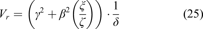
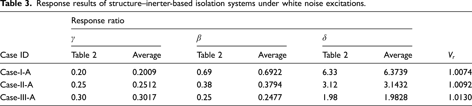
By adopting the IIS parameters presented in Table 2, a series of time history analyses were conducted for verification. Thirty randomly generated stationary white noise waves were adopted as external excitations. The average root mean square values of structural response ratios that contain , , and are presented in Table 3. The corresponding values of , , and obtained from the stochastic dynamic analysis (in Table 2) are also presented. To validate the derived displacement demand equation in (17), a verification ratio is defined as
of which the corresponding results are presented in Table 3.
Response results of structure–inerter-based isolation systems under white noise excitations.
It can be seen from Table 3 that the average responses of , , and (from the time history analysis) are similar to the values obtained from the stochastic dynamic analysis (in Table 2), which suggests that proposed equation (20) for the IIS parameter determination and displacement mitigation–oriented strategy is reliable. Furthermore, in the considered cases, the average result of is close to unity, which reflects the correctness of equation (17).
4.2. Case under target condition
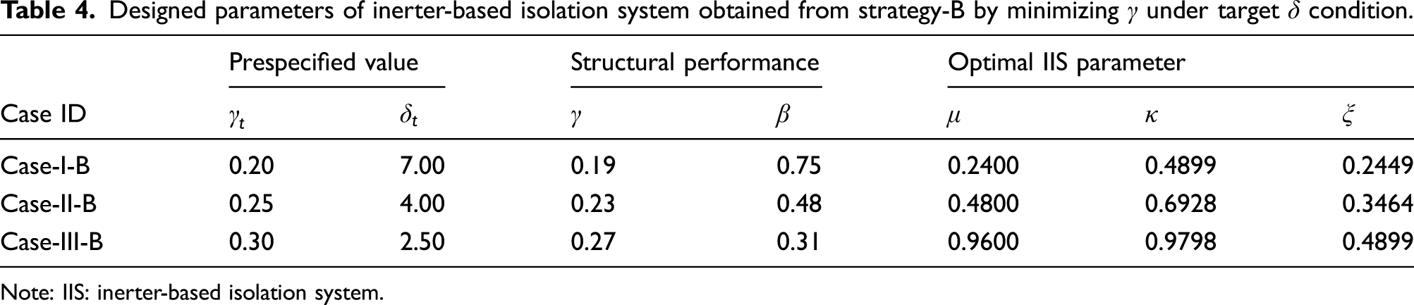
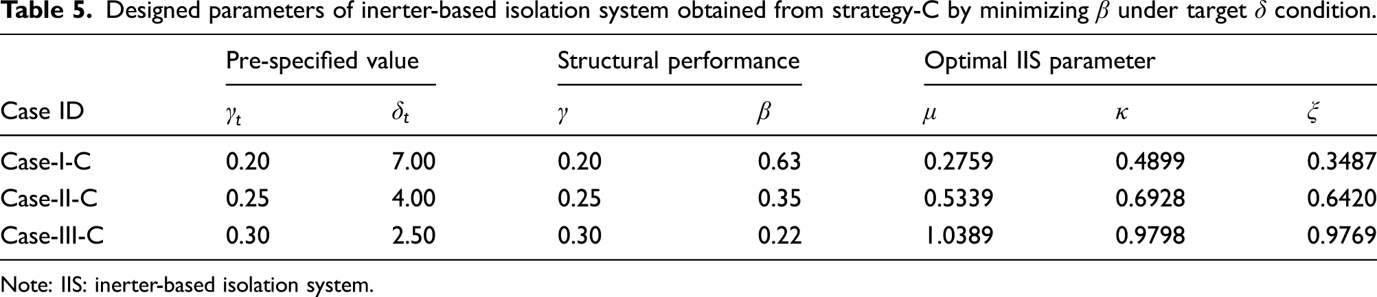
In Section 4.1, the IISs are designed in the constraint conditions of prespecified by minimizing the using equation (20). On the basis of the obtained , this section aims at prespecifying the displacement response, which contains and of the entire structure–IIS system quantitatively. As an example, used in this section are same as those in Section 4.1, whereas are assumed as 7.00 (Case-I), 4.00 (Case-II), and 2.50 (Case-III) to ensure the precondition in Table 2. On the premise of given and in each case, of the IIS is directly obtained by equation (19), and the additional parameters can be obtained by following the procedure in Figure 5. The results of the minimization of and are obtained from equations (22) and (24), respectively, and presented in Tables 4 and 5.
Designed parameters of inerter-based isolation system obtained from strategy-B by minimizing under target condition.
Case ID
Prespecified value
Structural performance
Optimal IIS parameter
Case-I-B
0.20
7.00
0.19
0.75
0.2400
0.4899
0.2449
Case-II-B
0.25
4.00
0.23
0.48
0.4800
0.6928
0.3464
Case-III-B
0.30
2.50
0.27
0.31
0.9600
0.9798
0.4899
Note: IIS: inerter-based isolation system.
Designed parameters of inerter-based isolation system obtained from strategy-C by minimizing under target condition.
Case ID
Pre-specified value
Structural performance
Optimal IIS parameter
Case-I-C
0.20
7.00
0.20
0.63
0.2759
0.4899
0.3487
Case-II-C
0.25
4.00
0.25
0.35
0.5339
0.6928
0.6420
Case-III-C
0.30
2.50
0.30
0.22
1.0389
0.9798
0.9769
Note: IIS: inerter-based isolation system.
Under the same upper displacement limit of the superstructure, that is in each case, it is of interest to compare the differences between the optimal design strategies A, B, and C. By comparing Tables 2, 4 and 5, the three optimal design criterions are all effective to provide the desired displacement performance to the isolated structure and ensure that the actual is equal to, or smaller than, the upper limit . Because of the minimization of in strategy-A, equation (20) essentially minimizes the stiffness of the isolator , however, at the cost of a large displacement of the isolation layer. Under the condition of corresponding to strategies B and C, a greater is sufficient to meet compared with the results obtained from equation (20) of strategy-A. In particular, the minimization of , that follows strategy-B in equation (22), provides the superstructure with a higher performance level , whereas the minimization of in strategy-C (equation (24)) provides the highest performance for the isolation layer of all three criteria.
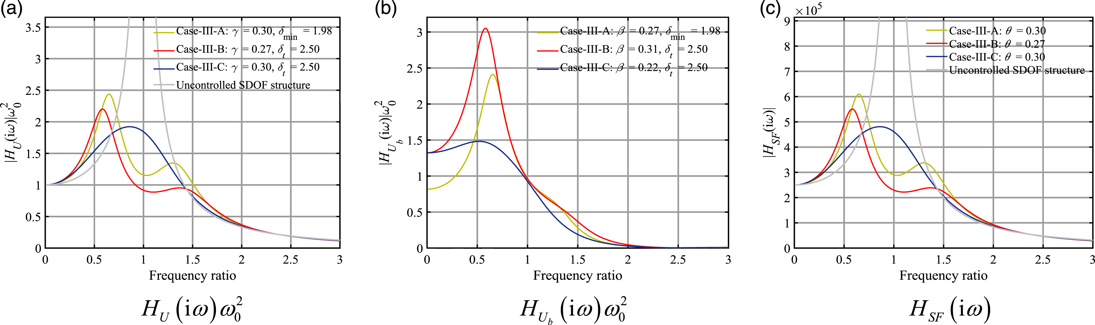
The frequency response functions of the displacements of the superstructure and isolation layer, and shear forces are also provided for design Cases-III-A, III-B, and III-C in Figure 6. By inspection of the frequency-domain responses, it can be observed that the IISs designed by the three strategies are effective to isolate the superstructure by reducing the transmitted shear forces, which provide expected isolation efficiency close to . The resonant displacement response of the superstructure decreases more clearly in Case-III-B, and the frequency bandwidth close to the resonance increases. In addition, the displacement of the isolation layer is suppressed more effectively in Case-III-C because of the pursuit of minimization of in strategy B.
Frequency response function curves of displacements of the superstructure and isolation layer, and shear force for Case-III-A to -III-C. (a) , (b) , and (c) .
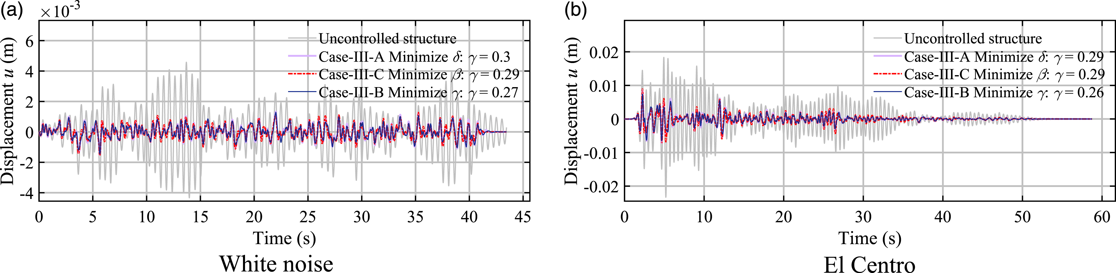
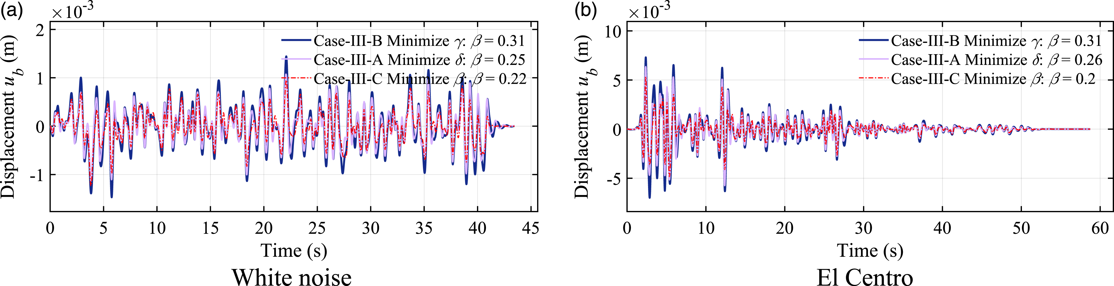
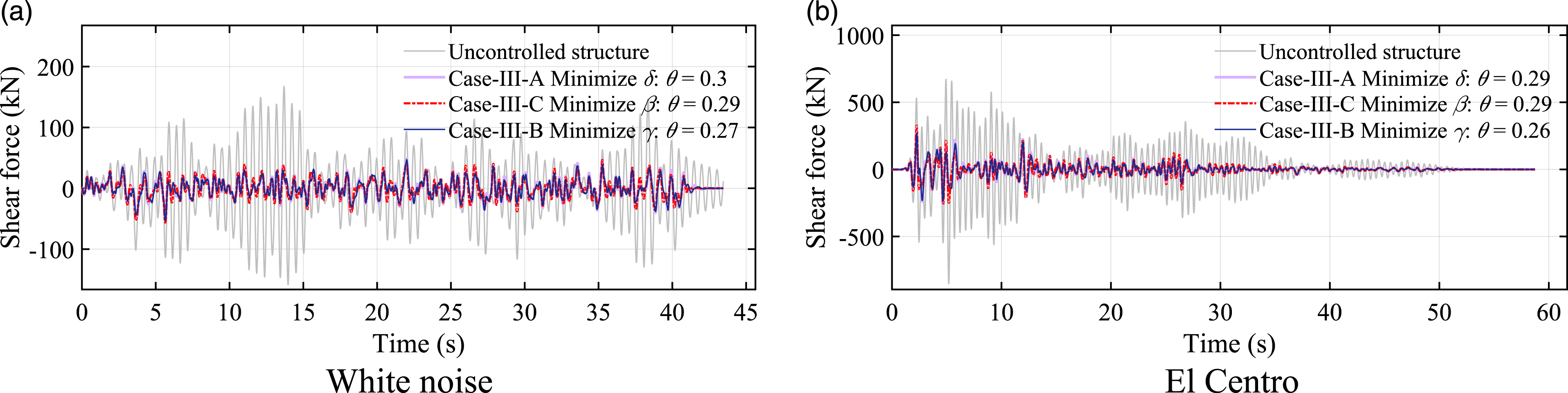
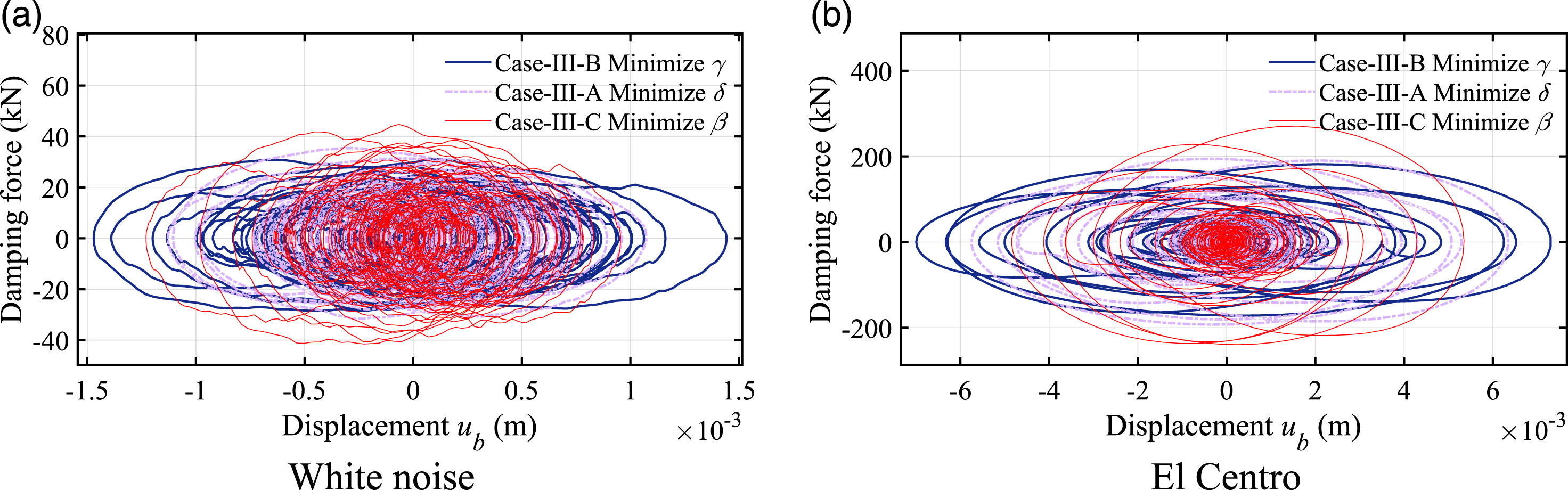
4.3. Time history analysis
Considering more realistic excitations, time history analyses were performed for white noise and the El Centro 1940 N–S record. For Cases-III-A, III-B, and III-C, the displacement responses of the superstructure , isolation layer , and the shear force are shown in Figures 7–9, respectively. The performance levels observed in these reduced responses, evaluated by , , and , match the specified values obtained from the design procedure. While a comprehensive analysis using a range of ground motions has not been conducted, this result suggests that the proposed displacement demand equation and optimization strategy under the assumption of white noise excitation can also produce a satisfactory performance for structures subjected to an actual seismic excitation. Figure 10 shows the corresponding hysteretic curves of the IIS dashpot to characterize the energy dissipation capacity and cost of the three proposed design strategies. In comparison with Case-III-A and -B, the damping deformation of the hysteretic curve in Case-III-C is the smallest, whereas the damping force is the maximum. Because of the pursuit of minimum in Case-II-C, a large damping ratio is used for efficient energy dissipation under the limitation of small damping deformation.
Displacement responses of uncontrolled structure and superstructures in Case-III-A to -III-C (Case-III-A, ; Case-III-B, ; and Case-III-C, ). (a) White noise and (b) El Centro.
Displacement responses of isolation layer in Case-III-A to -III-C (Case-III-A, ; Case-III-B, ; and Case-III-C, ). (a) White noise and (b) El Centro.
Shear force of uncontrolled structure and superstructure in Case-III-A to -III-C (Case-III-A, ; Case-III-B, ; and Case-III-C, ). (a) White noise and (b) El Centro.
Hysteretic curves of dashpot of inerter-based isolation system in Case-III-A to -III-C (Case-III-A, ; Case-III-B, ; and Case-III-C, ). (a) White noise and (b) El Centro.
5. Conclusions
The displacement mitigation mechanism, a theoretical basis governing the displacement relationship between the superstructure and the isolation layer, is established for an isolated structure–IIS by deriving a fundamental displacement demand equation. The primary conclusions can be summarized as:
The displacement demand equation explicitly explains the basic relationship between the displacement of the superstructure, isolation layer, and the entire structure–IIS systems theoretically. In addition, the functionality of IIS key parameters is clarified in terms of the displacement distribution pattern. From a theoretical perspective, the implementation of an inerter can decrease the displacements of the superstructure without a coupled increase in the displacement of the isolation layer, which is typically not seen in traditional isolation systems.
The displacement mitigation–oriented optimal design strategy explicitly quantifies the displacement performance of the entire structure–IIS system by using the displacement demand equation in a concise manner. The proposed optimal design method is effective to meet the desired superstructure displacement, while simultaneously ensuring satisfactory shear force and isolation layer displacement.
The displacement demand equation can simplify the design of IIS by directly determining the isolation frequency ratio for a prespecified displacement demand of the entire system. After the acquisition of this, the determination of the other IIS parameters, the inertance-mass ratio and damping ratio, is suggested by the pursuit of the minimization of the displacement of the isolation layer in the premise of the target isolation effectiveness.
The proposed displacement mitigation–oriented optimal design strategy is suitable for an IIS, whose effectiveness has been reflected in numerical results. In future studies, the corresponding experimental validation should be investigated for model structures isolated by the designed IIS. In this future experimental study, the intrinsic nonlinear behavior of the IIS should be considered and incorporated in the related optimal design.
Footnotes
Declaration of conflicting interests
The authors declared no potential conflicts of interest with respect to the research, authorship, and/or publication of this article.
Funding
The authors disclosed receipt of the following financial support for the research, authorship, and/or publication of this article: This study was supported by the National Natural Science Foundation of China (grant no. 51978525 and 51778489), the Foundation of Shanghai Science and Technology Commission (19DZ1202500), and the Natural Science Foundation of Shandong Province, China (grant no. ZR2018BEE033).
ORCID iD
Zhipeng Zhao
References
1.
AsaiTWatanabeY (2017) Outrigger tuned inertial mass electromagnetic transducers for high-rise buildings subject to long period earthquakes. Engineering Structures153: 404–410.
2.
ChenMPapageorgiouCScheibeF, et al. (2009) The missing mechanical circuit element. IEEE Circuits and Systems Magazine9(1): 10–26.
3.
CrandallSHMarkWD (1963) Random Vibration in Mechanical System. New York: Academic Press.
4.
De DomenicoDRicciardiG (2018) Optimal design and seismic performance of tuned mass damper inerter (TMDI) for structures with nonlinear base isolation systems. Earthquake Engineering & Structural Dynamics47(12): 2539–2560.
5.
EliseevSV (1978) Structural Theory of Vibration Protection Systems. Moscow: Nauka Publishing House.
6.
IkagoKSaitoKInoueN (2012) Seismic control of single-degree-of-freedom structure using tuned viscous mass damper. Earthquake Engineering & Structural Dynamics41(3): 453–474.
7.
JavidialesaadiAWierschemNE (2018) Optimal design of rotational inertial double tuned mass dampers under random excitation. Engineering Structures165: 412–421.
8.
JiangYZhaoZZhangR, et al. (2020) Optimal design based on analytical solution for storage tank with inerter isolation system. Soil Dynamics and Earthquake Engineering129: 105924.
9.
KawamataS (1973) Development of a Vibration Control System of Structures by Means of Mass Pumps. Tokyo, Japan: Institute of Industrial Science, University of Tokyo.
10.
MaRBiKHaoH (2020) Heave motion mitigation of semi-submersible platform using inerter-based vibration isolation system (IVIS). Engineering Structures219: 110833.
11.
MarianLGiaralisA (2014) Optimal design of a novel tuned mass-damper-inerter (TMDI) passive vibration control configuration for stochastically support-excited structural systems. Probabilistic Engineering Mechanics38: 156–164.
12.
NakaminamiSIkagoKInoueN (2012) Response Characteristics of a Base-Isolated Structure Incorporated with a Force-Restricted Viscous Mass Damper. In: 15th world conference on earthquake engineering, Lisbon, Portugal, 24–28 September 2012. Lisbon, Portugal: Sociedade Portuguesa de Engenharia Sismica (SPES).
13.
PanCZhangR (2018) Design of structure with inerter system based on stochastic response mitigation ratio. Structural Control and Health Monitoring25(6): e2169.
14.
RivinEI (2003) Passive Vibration Isolation. New York: ASME Press.
15.
SaitoKKuritaSInoueN (2007) Optimum response control of 1-DOF system using linear viscous damper with inertial mass and its Kelvin-type modeling. Journal of Structural Engineering55: 53–66.
16.
ShiXZhuS (2019) A comparative study of vibration isolation performance using negative stiffness and inerter dampers. Journal of the Franklin Institute356(14): 7922–7946.
17.
SmithMC (2002) Synthesis of mechanical networks: the inerter. IEEE Transactions on Automatic Control47(10): 1648–1662.
18.
SugiuraKWatanabeYAsaiT, et al. (2019) Experimental characterization and performance improvement evaluation of an electromagnetic transducer utilizing a tuned inerter. Journal of Vibration and Control26(1–2): 56–72.
19.
SunHZuoLWangX, et al. (2019) Exact H2 optimal solutions to inerter‐based isolation systems for building structures. Structural Control and Health Monitoring26(6): e2357.
20.
TaflanidisAAGiaralisAPatsialisD (2019) Multi-objective optimal design of inerter-based vibration absorbers for earthquake protection of multi-storey building structures. Journal of the Franklin Institute356(14): 7754–7784.
21.
TakewakiIMurakamiSYoshitomiS, et al. (2012) Fundamental mechanism of earthquake response reduction in building structures with inertial dampers. Structural Control and Health Monitoring19(6): 590–608.
22.
ZhangRZhaoZDaiK (2019) Seismic response mitigation of a wind turbine tower using a tuned parallel inerter mass system. Engineering Structures180: 29–39.
23.
ZhangRZhaoZPanC, et al. (2020) Damping enhancement principle of inerter system. Structural Control and Health Monitoring27(5): e2523.
24.
ZhaoZChenQZhangR, et al. (2020) Energy dissipation mechanism of inerter systems. International Journal of Mechanical Sciences184: 105845.
25.
ZhaoZChenQZhangR, et al. (2019) Optimal design of an inerter isolation system considering the soil condition. Engineering Structures196: 109324.
26.
ZhaoZZhangRJiangY, et al. (2019a) A tuned liquid inerter system for vibration control. International Journal of Mechanical Sciences164: 105171.
27.
ZhaoZZhangRJiangY, et al. (2019b) Seismic response mitigation of structures with a friction pendulum inerter system. Engineering Structures193: 110–120.