In this work, the damping characteristics of an actively constrained viscoelastic material layer are examined because of the inclusion of dispersed graphite particles within the viscoelastic material layer. The study is carried out by analysing the active–passive damping in a layered plate made of a substrate layer, a constrained viscoelastic particulate composite layer and a thin constraining piezoelectric actuator layer. The effective properties of the viscoelastic particulate composite are estimated using a differential scheme and the elastic–viscoelastic correspondence principle. The piezoelectric layer is activated according to the velocity feedback control law, and a closed-loop finite element model of the overall plate is derived for the analysis. The results reveal that the inclusion of graphite particles not only causes an improved transfer of active action from the piezoelectric layer to the substrate plate but also enhances the energy dissipation capability of the constrained viscoelastic layer. It is found that the maximum transfer of active action and the maximum passive damping capability of the viscoelastic particulate composite layer arise almost at the same volume fraction of inclusion. So, an optimal volume fraction of inclusion is obtained for significantly improved active–passive damping in the overall plate. The overall study presents a potential means of improved active–passive damping treatment of structural vibration.
In these available configurations of the ACLD treatment, the monolithic VEMs are used to achieve passive counterpart of the overall active–passive damping. The monolithic VEMs possess high energy dissipation capability, but they are incapable of transferring actuation force effectively from the active layer to substrate resulting in improper utilisation of the piezoelectric actuator layer. This shortcoming was reported by Liao and Wang (1996), where they introduced the edge elements for improved transfer of active action. However, in the present work, the same shortcoming is alleviated differently by incorporating dispersed graphite particles within the actively constrained viscoelastic damping layer. The inclusion of graphite particles certainly improves the stiffness of the actively constrained viscoelastic damping layer, and thus, the augmented transfer of active action in the ACLD treatment would appear. But, the loss factor of the same damping layer is expected to decrease due to the inclusion. Because of the increased stiffness and reduced loss factor of the damping layer, the passive counterpart of the overall active–passive damping in the ACLD treatment either improves or deteriorates depending on the volume fraction of inclusion (VFI) in the damping layer. It implies both the possibilities of enhanced and reduced passive action in the ACLD treatment, while the augmented active action is expected through the inclusion in the damping layer. A detailed study on this issue may provide an augmented ACLD treatment through the design of a viscoelastic particulate composite (VEPC) damping layer, and this study is carried out at present for the ACLD treatment of vibration of plates. The effective properties of the VEPC damping layer are estimated theoretically, and the damping in the ACLD treatment is analysed by deriving a closed-loop finite element (FE) model of the overall plate. The numerical results mainly reveal the active–passive damping characteristics of the ACLD treatment for the variation of the VFI of dispersed graphite particles in the viscoelastic damping layer.
2. Mathematical formulation
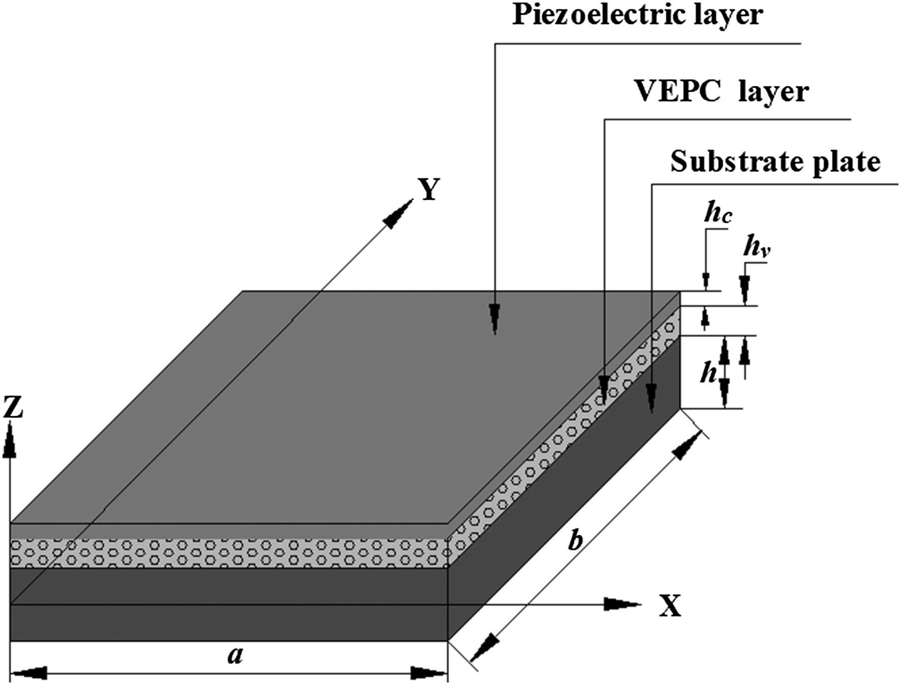
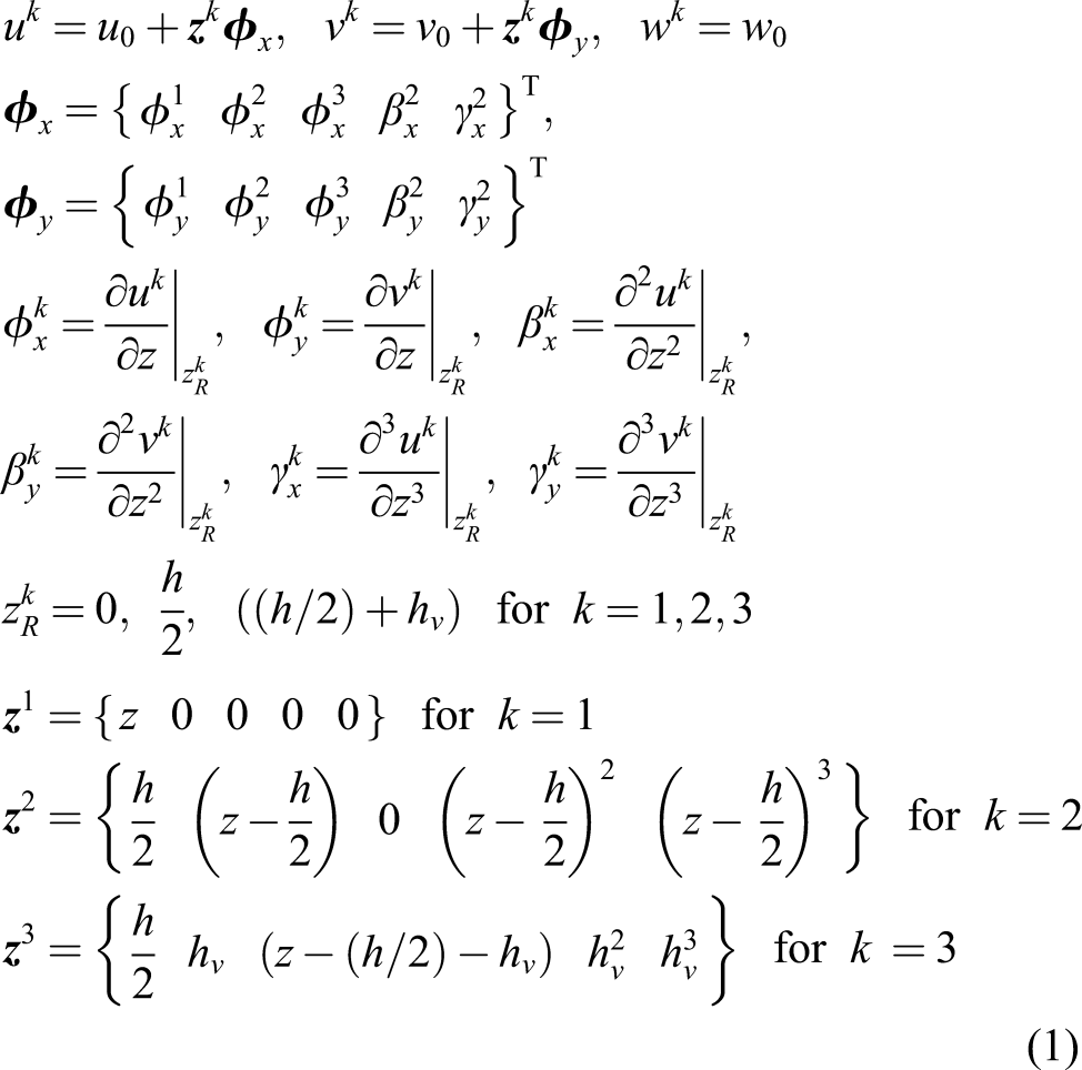
Figure 1 shows a substrate plate integrated with a VEPC layer constrained by a piezoelectric actuator layer. Because the laminate is composed of thin component layers, the kinematics of deformation of every layer can be defined following the first-order shear deformation theory (Cupiał and Nizioł, 1995). However, presently, the constrained viscoelastic layer is modelled by the third-order shear deformation theory, and thus, the displacement components , and at any point of the overall plate along the , and directions, respectively, can be written as (Reddy, 2003)
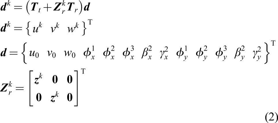
where the superscript indicates the substrate plate, constrained layer and constraining layer as per its values as 1, 2 and 3, respectively; , and are the displacements at a point on the middle plane of the substrate plate along the , and directions, respectively. The displacement components (, , ) at any point within the layer can be expressed as
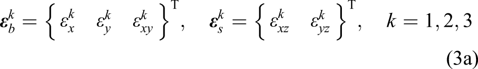
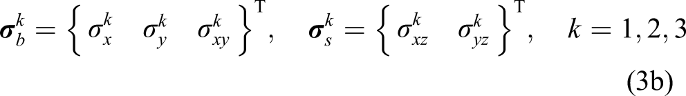
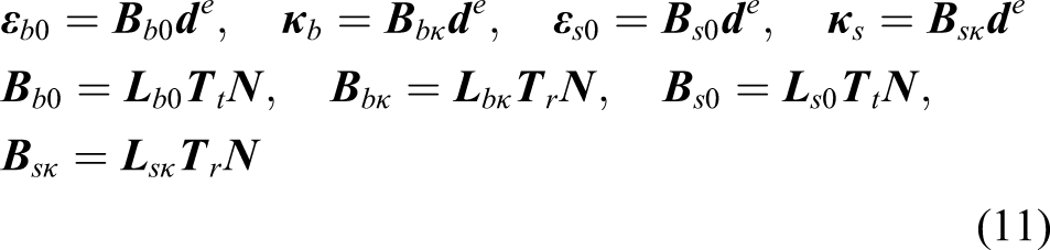
where represents the null vector; and are the transformation matrices. The state of strain and the state of stress at any point within a layer can be written as
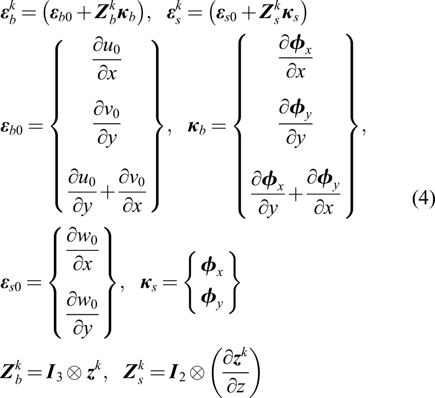
where the symbols and represent strain and stress components, respectively; the subscripts and indicate the normal stress or strain along the and directions, respectively; the subscripts , and denote the shear strain or stress on the , and planes, respectively. The strain–displacement relations for the layer can be written as
where represents the Kronecker product.
Schematic diagram of a substrate plate integrated with an actively constrained viscoelastic layer with the inclusion of graphite particles.
2.1. Properties of the constituent materials
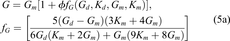
The present VEPC is considered to be made of uniform spherical graphite particles distributed dispersedly within the butyl rubber matrix. The linear constitutive behaviour of these homogeneous isotropic materials is assumed. The properties of butyl rubber are dependent on the operating temperature and frequency. Presently, the operating temperature is considered as the room temperature so that the properties of butyl rubber, as well as the effective properties of VEPC, are dependent on the operating frequency only. If the elastic matrix is considered instead of the viscoelastic matrix and a small value of VFI is taken in comparison with 1, then the effective bulk and shear moduli of the particulate composite are given by (Hsiao-Sheng and Acrivos, 1978; Walpole, 1972)
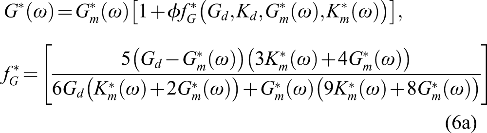
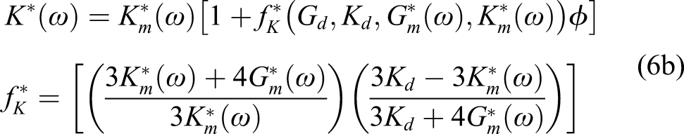
where a quantity for matrix or particles is denoted by the subscript or . For the viscoelastic matrix instead of the elastic matrix, equations (5a) and (5b) can be modified according to the elastic–viscoelastic correspondence principle (Hashin, 1965), where the moduli of the elastic matrix in the analytical expressions (equations (5a) and (5b)) are replaced by the complex moduli of the viscoelastic matrix as
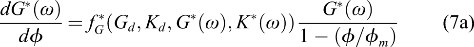
where a complex quantity is denoted by the superscript (). Equations (6a) and (6b) are valid for the dilute concentration of solid particles in the VEPC. However, for an increased VFI , the effective properties of the VEPC can be computed using a differential scheme as (Krieger and Dougherty, 1959; Pal, 2005)
where is the differential increment of and is the maximum packing volume fraction of undeformed solid particles. The value of is presently considered as 0.637 for the random close packing (RCP) of uniform spherical particles (Tagliavia et al., 2009).
For a specified VFI , the effective moduli of the VEPC at an operating frequency can be obtained by the solution of equations (7a) and (7b), where the initial conditions areandfor . Besides, the effective mass density of the VEPC is presently computed following the rule of mixture as
where and are the mass densities of the inclusion and matrix phase, respectively.
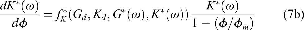
The substrate plate is made of an elastic isotropic material. The VEPC is a macroscopically homogeneous isotropic material with the aforesaid effective properties. The piezoelectric layer is transversely poled and activated by supplying the external voltage across its top and bottom fully electrode surfaces. As it is a very thin active constraining layer, the electric field components , and along the , and directions, respectively, can be assumed as , and . Accordingly, the constitutive relations for a layer can be written as
where and are the bending and transverse shear counterparts of the stiffness matrix for layer; is a vector of the piezoelectric coefficients associated with for layer; is the electric displacement component along the direction for layer; and is the electrical permittivity associated with for layer; . Furthermore, the stiffness matrices are the frequency-dependent complex quantities only for the VEPC layer .
2.2. FE governing equation of motion
For deriving the FE model of the overall plate, the rectangular reference plane, that is the middle plane of the substrate plate is discretized using nine-node quadrilateral isoparametric elements. Every element is in the shape of the rectangle with the edges in parallel to the in-plane axial directions. The displacement vector and the strain vectors at any point within an element can be expressed in terms of the shape function matrix and the elemental nodal displacement vector as
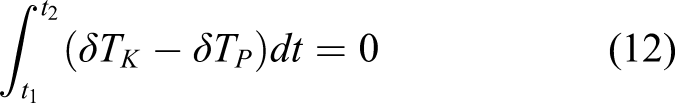
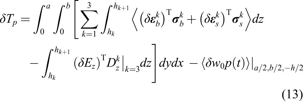
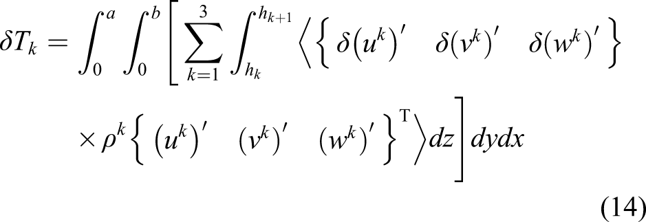
where , , and are the operator matrices that can be obtained from equation (4). The overall plate is considered to vibrate under a transverse harmonic point load at a point . The corresponding governing equation of motion is derived using Hamilton’s principle (equation (12)), where the first variations of the total potential energy and the total kinetic energy of the overall plate at an instant of time can be expressed by equations (13) and (14)
In equations (12)–(14), is an operator for the first variation; the superscript (') denotes first-order derivative of a quantity with respect to time; is the mass density of layer; and represent the coordinates of the bottom and top surfaces of layer, respectively. Using equations (9)–(11) into (12)–(14), the elemental equation of motion can be obtained as
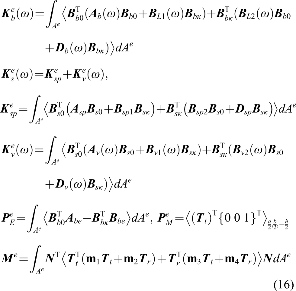
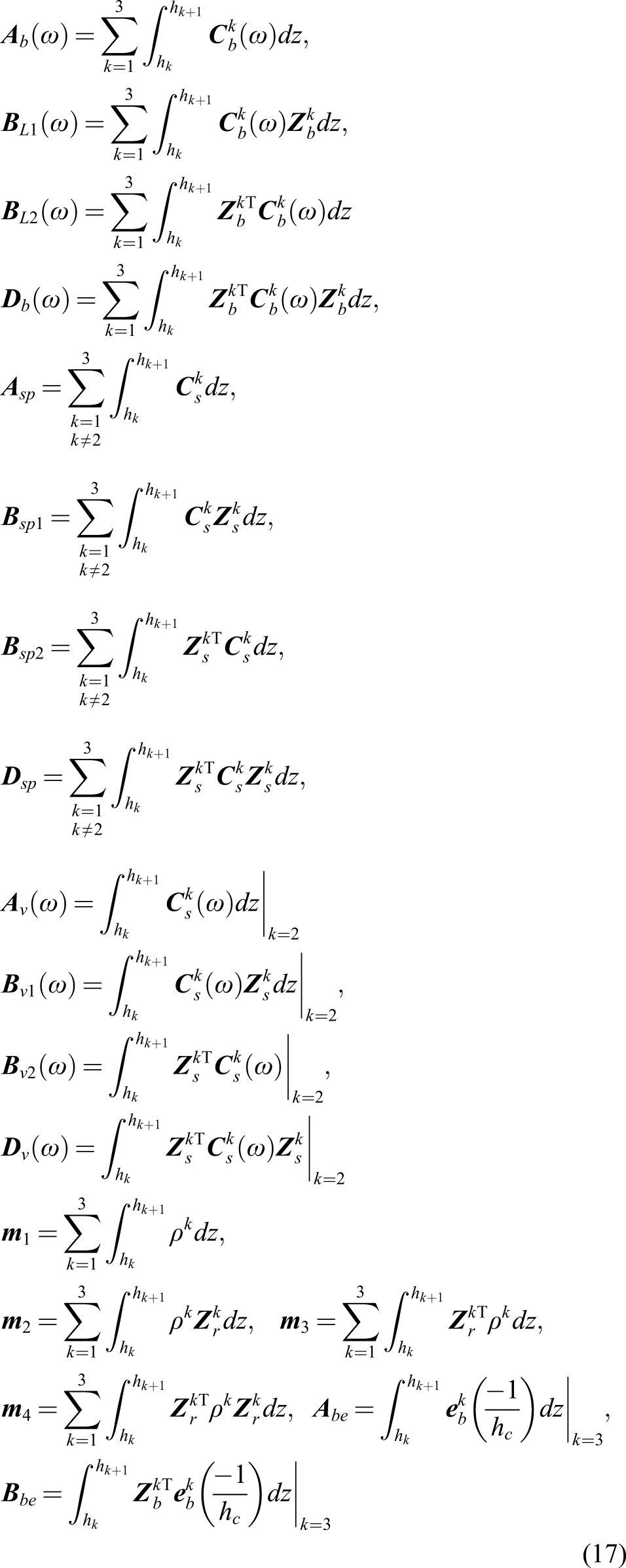
In equations (15) and (16), the superscript (") denotes second-order derivative of a quantity with respect to time; is the elemental area and the other matrices are as follows
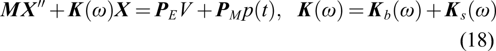
Assembling the elemental equations (equation (15)), the following global equation of motion of the overall plate can be obtained
where is the global mass matrix, and are the bending and transverse shear counterparts of the global stiffness matrix and and are the global nodal electro elastic and load coefficient vectors, respectively; is the global nodal displacement vector.
The piezoelectric constraining layer is activated according to the velocity feedback control strategy as
where is the transverse velocity sensed at the middle point on the top surface of the overall plate and is the velocity feedback control gain. Now, can be expressed in terms of through a transformation row matrix according to equation (20), and then, the governing equation of motion (equation (18)) can be expressed in the form as given in equation (21)
3. Numerical results and discussions
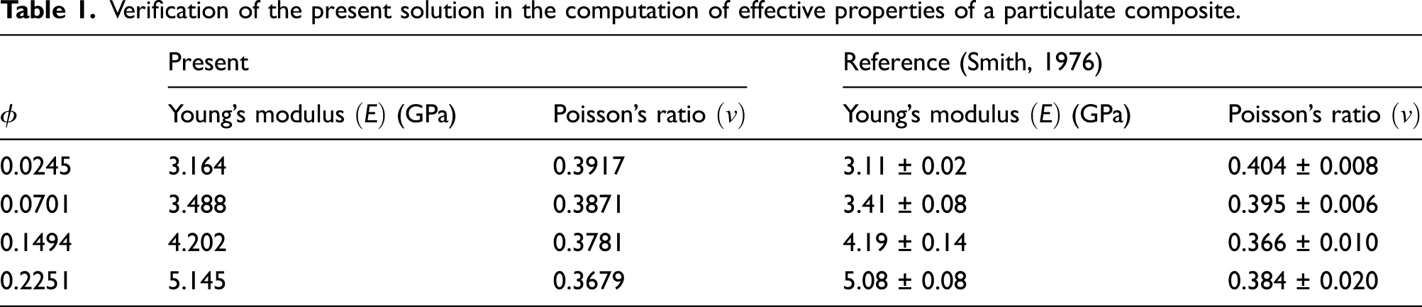
The inclusion of solid particles in the VEPC is made of graphite (, and ), whereas the matrix phase is made of butyl rubber. The frequency-dependent material properties of butyl rubber at room temperature (32°C) are taken from Jones (2001), and Poisson’s ratio and mass density of the same material are taken as 0.49 and 920 kg/m3, respectively. The effective properties of the VEPC are computed by the solution of equations (7a) and (7b) using MATLAB function ode45. For verification of this solution, the reference results are taken from Smith (1976) for the effective properties of a polymer-based particulate composite with the inclusion of spherical glass particles. Table 1 illustrates these reference results along with similar results computed at present for the same composite. This comparison verifies the present solution for effective material constants of particulate composites.
Verification of the present solution in the computation of effective properties of a particulate composite.
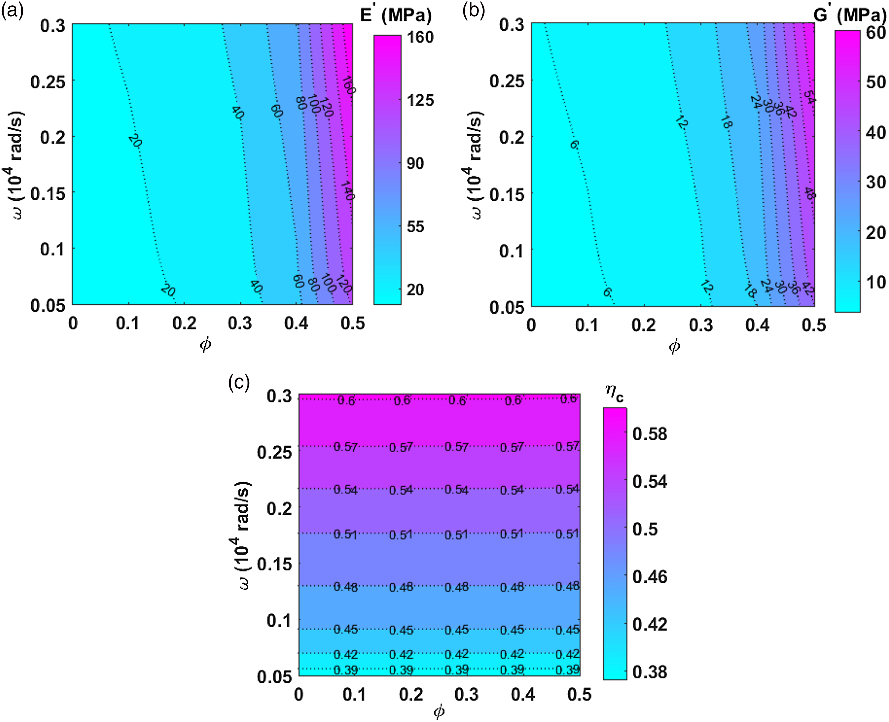
An operating frequency range is first chosen, and also, a range of the values of VFI is taken without exceeding the maximum VFI in the RCP of particles. Accordingly, a two-dimensional domain of and is identified, and the grid points are generated. At every grid point, the frequency-dependent properties of butyl rubber are first taken from Jones (2001), and then the effective properties of VEPC are computed by the solution of equations (7a) and (7b). The corresponding results illustrate the variations of effective properties of the VEPC in the two-dimensional domain of and as shown in Figure 2(a)–(c).
Variations of the effective (a) storage Young’s modulus , (b) storage shear modulus and (c) loss factor of VEPC within the two-dimensional domain of operating frequency and VFI . Note: VEPC: viscoelastic particulate composite; VFI: volume fraction of inclusion.
For any VFI , Figure 2(a)–(c) shows that the effective storage modulus and loss factor () increase with the increasing operating frequency because of the corresponding increase of the same material constants of the matrix phase. However, for a constant operating frequency, it may be observed from Figures 2 and 3 that increases significantly with the increasing VFI whereas decreases slowly. The effect of these changes in the effective properties of the passive damping layer on the characteristics of the ACLD treatment is investigated through the subsequent results.
Variations of the effective (a) storage Young’s modulus , (b) storage shear modulus and (c) loss factor of VEPC with the VFI at two different frequencies. Note: VEPC: viscoelastic particulate composite; VFI: volume fraction of inclusion.
The present investigation on the active–passive damping characteristics of the actively constrained VEPC layer is carried out by evaluating the modal loss factor and frequency responses of the overall plate (Figure 1). The geometrical properties of the overall plate are taken as , , and . Unless otherwise mentioned, the thickness of the VEPC layer is taken as . The substrate plate is considered to be made of aluminium (, and ), whereas the piezoelectric layer is made of PZT-5H (Erturk and Inman, 2011) having the properties as , , , , , , , , and . The edges of the substrate plate are considered as the clamped edges (, , , , at and ), whereas the frequency responses and modal loss factor of the overall plate are evaluated corresponding to the fundamental bending mode of vibration.
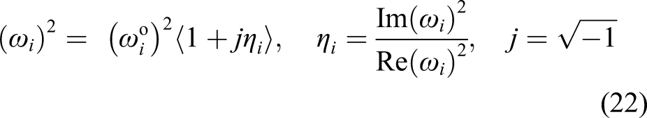
The modal loss factor is evaluated through the free vibration analysis of the overall plate, where a complex quadratic eigenvalue problem arises. Firstly, it is solved using the direct iteration method to obtain the complex natural frequency . Subsequently, the natural frequency and the modal loss factor for mode of vibration of the overall plate are computed by (Hu et al., 2008)
It may be noted here that the damping in the ACLD treatment arises because of the active action only when and . In parallel, the damping in the ACLD treatment appears because of the passive action only when and . For nonzero values of and , the damping arises because of both the active and passive actions in the ACLD treatment. However, besides the modal loss factor, the frequency responses of the overall plate around the fundamental natural frequency are evaluated for the aforesaid transverse harmonic point load in the form as , where is the load amplitude. These frequency responses are presented by the maximum transverse displacement amplitude over the plane of the plate at every operating frequency.
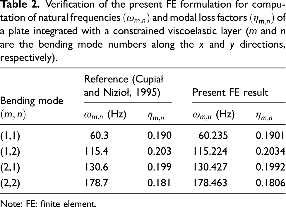
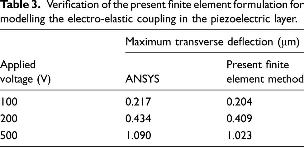
For verification of the present FE model in the computation of modal loss factor, the passively constrained damping layer is considered to be made of monolithic VEM, and the natural frequencies, as well as modal loss factors, are computed. These results are illustrated in Table 2 together with similar results for an identical plate analysed in Cupiał and Nizioł (1995). This comparison (Table 2) verifies the present FE formulation for computation of the modal loss factor of a plate integrated with a constrained viscoelastic layer. For further verification of the present FE formulation in modelling the electro-elastic coupling within the piezoelectric layer, the viscoelastic layer is taken with a negligibly small thickness . The maximum transverse deflection of this plate is computed for the applied voltage across the thickness of the piezoelectric layer. Similar results are also evaluated from the ANSYS model of the same plate, and it is observed that the present results are very close to the results obtained from the ANSYS model of the plate (Table 3). This comparison verifies the present FE formulation for handling the electro-elastic coupling in the piezoelectric layer.
Verification of the present FE formulation for computation of natural frequencies and modal loss factors of a plate integrated with a constrained viscoelastic layer ( and are the bending mode numbers along the and directions, respectively).
Verification of the present finite element formulation for modelling the electro-elastic coupling in the piezoelectric layer.
Applied voltage (V)
Maximum transverse deflection (μm)
ANSYS
Present finite element method
100
0.217
0.204
200
0.434
0.409
500
1.090
1.023
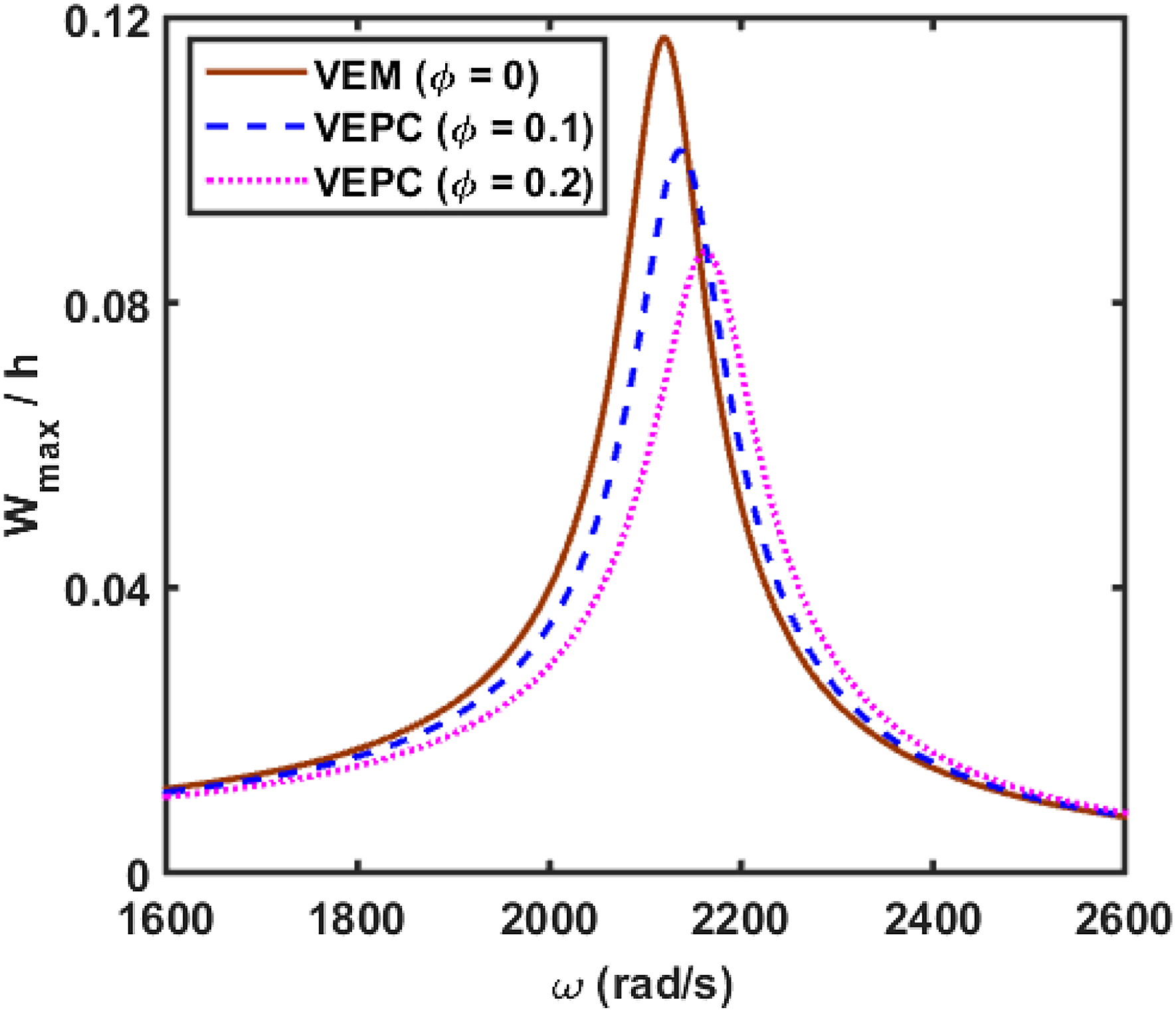
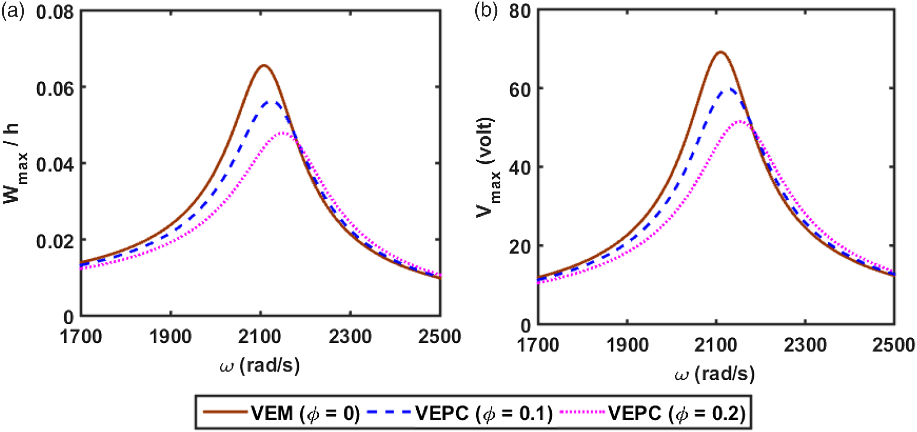
Figures 4 and 5(a) illustrate the frequency responses of the overall plate for different values of VFI (), when the piezoelectric layer is either activated or deactivated . Figure 5(b) shows the variations of the required control voltage corresponding to the frequency responses in Figure 5(a). Figures 4 and 5(a) show that the attenuation of the resonant displacement amplitude through the passive or the active–passive damping in the overall plate increases significantly due to the inclusion of graphite particles in the viscoelastic layer. Also, the required control voltage for the active–passive damping decreases because of the inclusion in the viscoelastic layer (Figure 5(b)).
Frequency response of the overall plate for different volume fraction of inclusion of graphite particles .
(a) Frequency responses of the overall plate and (b) corresponding variations of the control voltage for different volume fraction of inclusion of graphite particles .
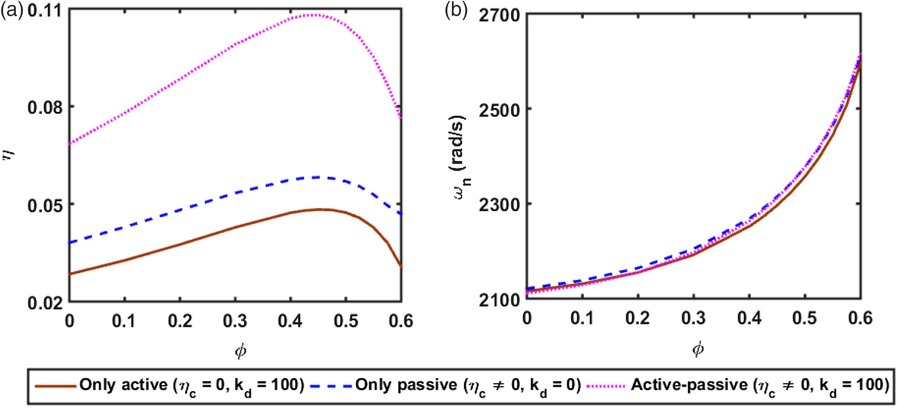
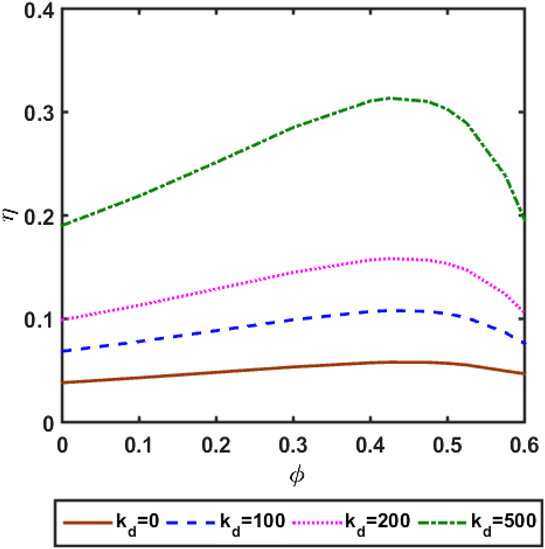
However, for investigating the effect of the inclusion on the active (, ), passive (, ) and active–passive (, ) actions in the ACLD treatment, the corresponding variations of damping with VFI are presented in Figure 6(a). It may be observed from Figure 6(a) that the active damping (, ) first increases and then decreases after a certain value of the increasing VFI . In fact, the increased stiffness of the viscoelastic layer due to the inclusion (Figure 2(a) and (b)) results in an improved transfer of active action from the piezoelectric layer to the substrate plate. Concurrently, the enhanced stiffness of the viscoelastic layer not only causes increased flexural rigidity of the overall plate but also affects the actuating moment in the active action through the reduced distance of the actuator layer from the neutral plane of bending deformation. The combined effect of these facts results in an optimal value of VFI for the maximum active damping.
Variations of (a) modal loss factor and (b) natural frequency with the VFI for active , passive and active–passive actions in the ACLD treatment. Note: VFI: volume fraction of inclusion; ACLD: active constrained layer damping.
Similar to the active damping (, ), the passive damping (, ) in the overall plate also increases with the increasing VFI , and the maximum passive damping appears at a certain value of (Figure 6(a)). Here, the stored energy in the damping layer increases with the increase in VFI (Figure 2(a) and (b)), but the corresponding decrease of (Figure 3) causes an optimal value of VFI for the maximum passive damping. However, the active–passive damping appears with their maximum values almost at the same value of VFI , and it results in significantly improved active–passive damping in the overall plate (Figure 6(a)). Besides the improved active–passive damping, the inclusion of graphite particles causes the increased natural frequency of the overall plate (Figure 6(b)). However, this increment of natural frequency may not appear remarkably at the optimal value of VFI where active–passive damping appears with its maximum value.
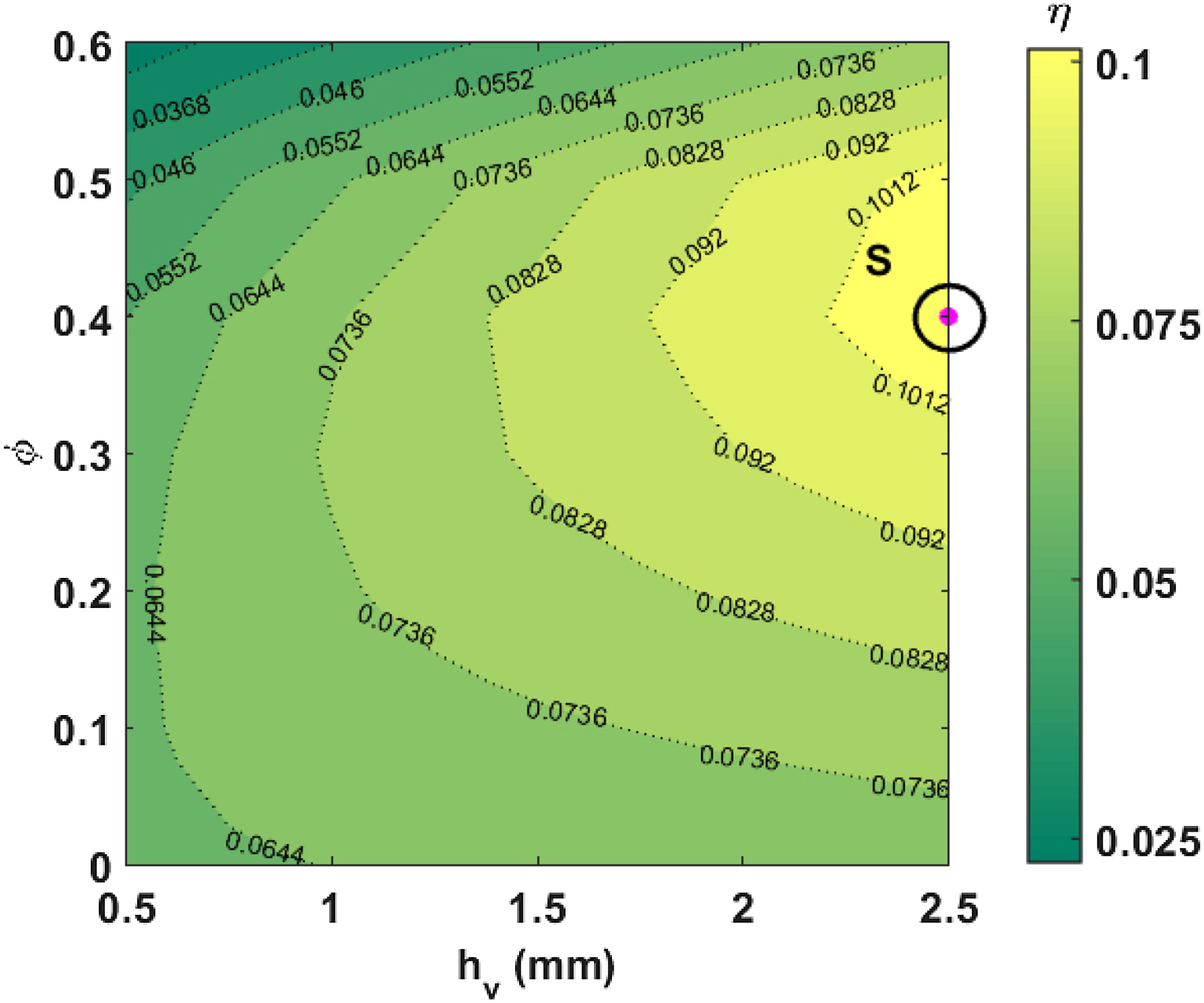
To investigate the combined effect of the VFI and thickness of the VEPC layer on the damping capability of the ACLD treatment, the variation of active–passive damping over the two-dimensional domain of and is evaluated as shown in Figure 7. Figure 7 shows that the active–passive damping in the overall plate continues to increase with the increasing value of . However, the effect of on appears indicatively within a particular range of VFI where the optimal value of VFI corresponding to the maximum damping arises as 0.4 (point S, Figure 7). From this result, a value of is considered as 2.5 mm, and the variation of with is evaluated for different values of the control gain as shown in Figure 8. Figure 8 shows that the optimal value of remains almost the same for any value of , but the versus slope increases significantly for an increase in the value of .
Variation of the modal loss factor within the two-dimensional domain of VFI and thickness of the VEPC layer . Note: VEPC: viscoelastic particulate composite; VFI: volume fraction of inclusion.
Variation of the modal loss factor with the volume fraction of inclusion at different values of the control gain .
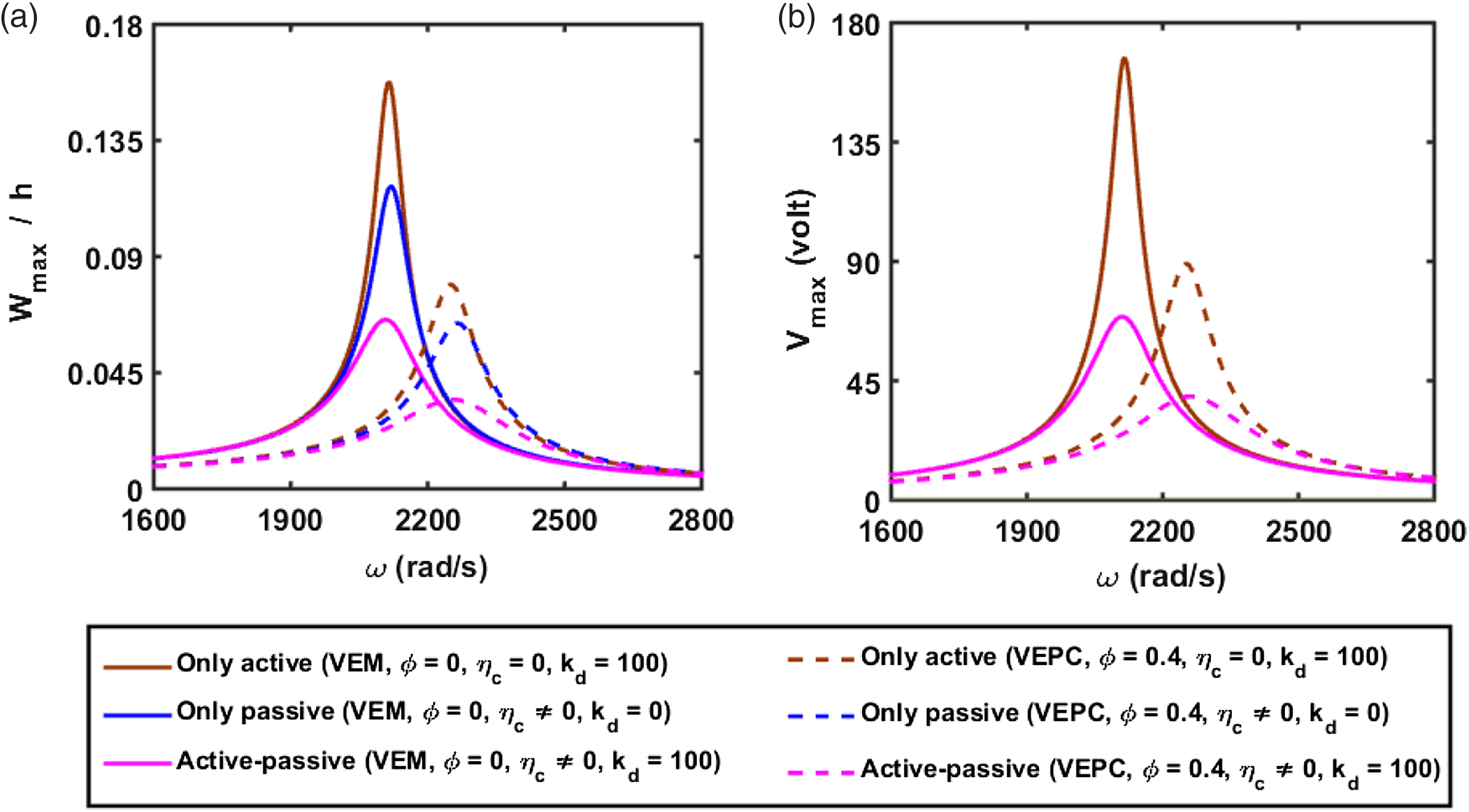
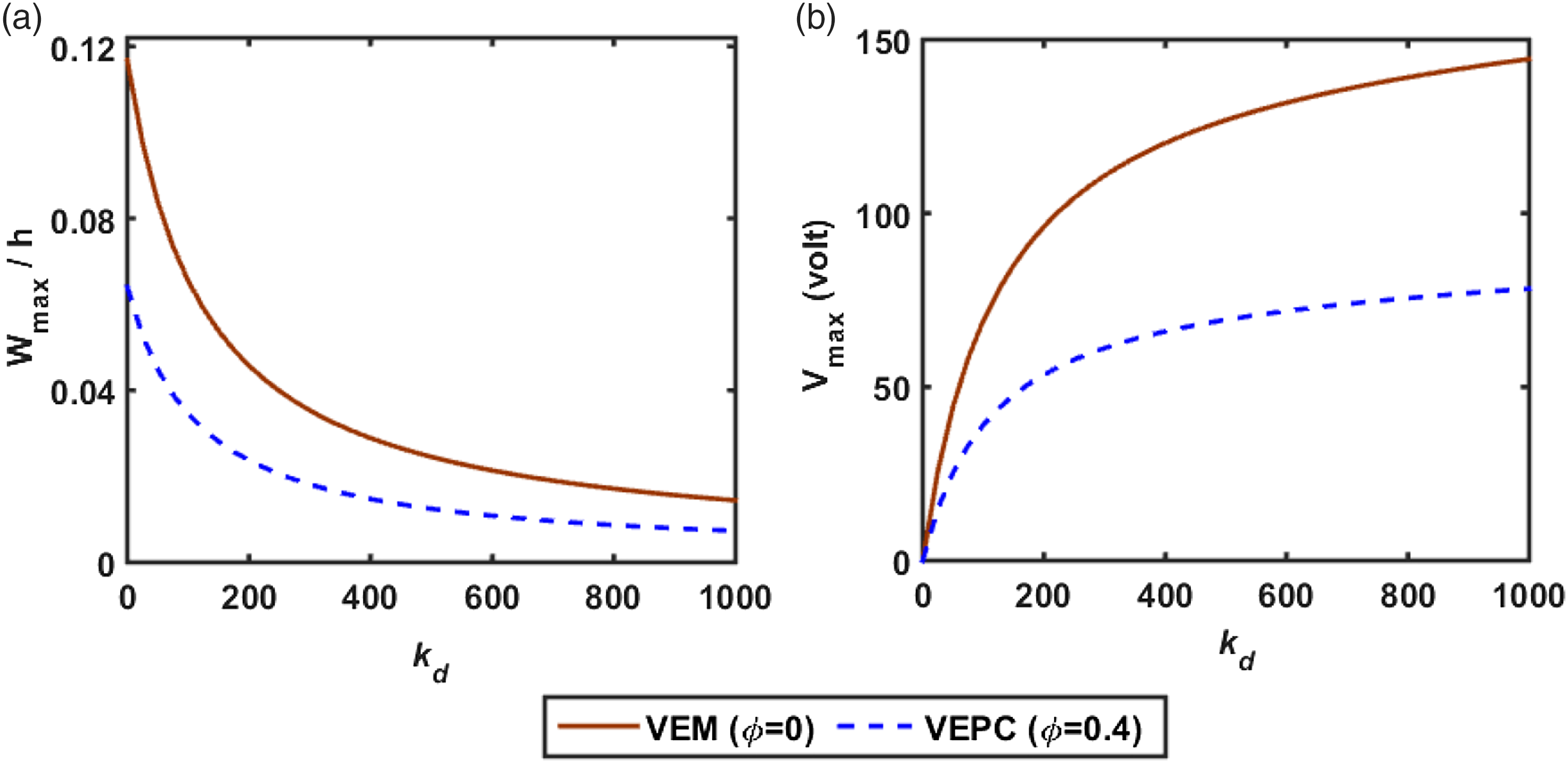
On the basis of the aforesaid results, the values of and are taken as 0.4 and 2.5 mm, respectively, and the attenuation of resonant displacement amplitude of the overall plate is illustrated in Figure 9(a) for active , passive and active–passive damping. Similar responses for the monolithic VEM layer instead of the VEPC layer are also illustrated in Figure 9(a). Figure 9(b) shows the variations of the control voltage for the frequency responses in Figure 9(a). For any case of the active, passive and active–passive damping, Figure 9(a) shows significantly improved attenuation of the resonant displacement amplitude for the use of the present VEPC instead of the monolithic VEM. Also, the required control voltage for active or active–passive damping decreases the use of VEPC instead of VEM (Figure 9(b)). The results in Figure 9 are evaluated at a constant value of . However, for different values of , the corresponding variations of the resonant displacement amplitude and control voltage are illustrated in Figure 10(a) and (b), respectively, where the active–passive damping is achieved either through monolithic VEM or VEPC. For any case of VEM and VEPC, Figure 10(a) shows that a good active–passive damping in the overall plate can be achieved by increasing the value of . But, the superior attenuation of vibration amplitude arises for the VEPC by supplying remarkably less control voltage (Figure 10(b)). These results imply the present VEPC as a potential damping material for the active–passive damping treatment of structural vibration.
(a) Frequency responses of the overall plate and (b) corresponding variations of control voltage for active, passive and active–passive damping .
Variations of (a) the resonant displacement amplitude and (b) corresponding control voltage (Vmax) with the control gain .
4. Conclusion
In this work, the damping characteristics of an actively constrained VEPC layer are investigated by integrating it over the surface of a substrate plate. The VEPC layer is achieved by the inclusion of graphite particles within the butyl rubber matrix. The effective properties of this VEPC layer are estimated using a differential scheme and the elastic–viscoelastic correspondence principle. The VEPC layer is constrained by a piezoelectric actuator layer that is activated by supplying external voltage according to the velocity feedback control law. With this arrangement, a closed-loop FE model of the overall plate is derived and the active–passive damping characteristics of the actively constrained VEPC layer are studied mainly for the variation of the VFI of graphite particles.
The analysis reveals that the inclusion of graphite particles in the viscoelastic layer not only causes an augmented transfer of active action from the piezoelectric actuator layer to the substrate plate but also results in enhanced passive damping capability of the constrained viscoelastic layer. As a result, the active–passive damping in the overall plate significantly increases. However, this improvement of active–passive damping can be achieved up to a certain value of the VFI, where an optimal VFI arises for the maximum damping. Further study on the active–passive control of frequency responses of the overall plate reveals significantly improved attenuation of resonant displacement amplitude at the expense of the lesser control voltage, when the conventional monolithic VEM layer is converted to the VEPC layer through the optimal VFI of graphite particles. These observations imply the present VEPC as a potential damping material for ACLD treatment of structural vibration.
Footnotes
Declaration of conflicting interests
The authors declared no potential conflicts of interest with respect to the research, authorship, and/or publication of this article.
Funding
The authors received no financial support for the research, authorship, and/or publication of this article.
ORCID iD
Satyajit Panda
References
1.
ArafaMBazA (2000) Dynamics of active piezoelectric damping composites. Composites Part B: Engineering31(4): 255–264.
2.
BatraRCLiangXQYangJS (1996) The vibration of a simply supported rectangular elastic plate due to piezoelectric actuators. International Journal of Solids and Structures33(11): 1597–1618.
3.
BazAPohS (1988) Performance of an active control system with piezoelectric actuators. Journal of sound and Vibration126(2): 327–343.
4.
BazARoJ (1995) Performance characteristics of active constrained layer damping. Shock and Vibration2(1): 33–42.
5.
CrawleyEFDe LuisJ (1987) Use of piezoelectric actuators as elements of intelligent structures. AIAA journal25(10): 1373–1385.
6.
CupiałPNiziołJ (1995) Vibration and damping analysis of a three-layered composite plate with a viscoelastic mid-layer. Journal of Sound and Vibration183(1): 99–114.
7.
ErturkAInmanDJ (2011) Piezoelectric Energy Harvesting. New York: John Wiley and Sons.
8.
GentilmanRLFioreDFPhamHT, et al. (1994) Fabrication and Properties of 1-3 PZT-Polymer Composites (No. CONF-931142). Westerville, OH: American Ceramic Society.
9.
GhoneimH (1993) Electromechanical surface damping using constrained layer and shunted piezoelectric. Smart Structures and Materials 1993: Mathematics in Smart Structures1919: 78–89.
10.
HashinZ (1965) Viscoelastic behavior of heterogeneous media. Journal of Applied Mechanics32(3): 630–636.
11.
Hsiao-ShengCAcrivosA (1978) The effective elastic moduli of composite materials containing spherical inclusions at non-dilute concentrations. International Journal of Solids and Structures14(5): 349–364.
12.
HuHBelouettarSDayaEMM (2008) Review and assessment of various theories for modeling sandwich composites. Composite Structures84(3): 282–292.
13.
JonesDI (2001) Handbook of Viscoelastic Vibration Damping. New York: John Wiley and Sons.
14.
KriegerIMDoughertyTJ (1959) A mechanism for non‐Newtonian flow in suspensions of rigid spheres. Transactions of the Society of Rheology3(1): 137–152.
15.
KumarR (2012) Active vibration control of beams by combining precompressed layer damping and active constrained layer damping treatment: performance comparison of various robust control techniques. Journal of Vibration and Acoustics134(2): 021015.
16.
KumarSKumarRSehgalR (2011) Enhanced active constrained layer damping treatment using stand-off-layer: FEM based design and experimental vibration analysis. Applied Acoustics72(11): 856–872.
17.
KungSWSinghR (1998) Vibration analysis of beams with multiple constrained layer damping patches. Journal of Sound and Vibration212(5): 781–805.
18.
LamMJSaundersWRInmanDJ (1995) Modeling active constrained-layer damping using Golla–Hughes–McTavish approach. Smart Structures and Materials 1995: Passive Damping2445: 86–97.
19.
LiaoWHWangKW (1996) A new active constrained layer configuration with enhanced boundary actions. Smart Materials and Structures5(5): 638.
20.
LiuYWangKW (2000) Active-passive hybrid constrained layer for structural damping augmentation. Journal of vibration and acoustics122(3): 254–262.
21.
PalR (2005) New models for effective Young’s modulus of particulate composites. Composites Part B: Engineering36(6–7): 513–523.
22.
PandaSKumarA (2018) A design of active constrained layer damping treatment for vibration control of circular cylindrical shell structure. Journal of Vibration and Control24(24): 5811–5841.
23.
ParkCHBazA (2001) Comparison between finite element formulations of active constrained layer damping using classical and layer-wise laminate theory. Finite Elements in Analysis and Design37(1): 35–56.
24.
RayMCBazA (1997) Optimization of energy dissipation of active constrained layer damping treatments of plates. Journal of Sound and Vibration208(3): 391–406.
25.
ReddyJN (2003) Mechanics of Laminated Composite Plates and Shells: Theory and Analysis. New York: CRC Press.
26.
RoyPKGanesanN (1996) Dynamic studies on beams with unconstrained layer damping treatment. Journal of Sound and Vibration195(3): 417–427.
27.
SaravananCGanesanNRamamurtiV (2001) Semianalytical finite element analysis of active constrained layer damping in cylindrical shells of revolution. Computers & Structures79(11): 1131–1145.
28.
SmithJC (1976) Experimental values for the elastic constants of a particulate-filled glassy polymer. Journal of Research of the National Bureau of Standards80: 45–49.
29.
SwallowW (1939) An improved method of damping panel vibrations. British Patent Specification513: 171.
30.
TagliaviaGPorfiriMGuptaN (2009) Vinyl ester-glass hollow particle composites: dynamic mechanical properties at high inclusion volume fraction. Journal of Composite Materials43(5): 561–582.
31.
UngarEEKerwinEMJr (1964) Plate damping due to thickness deformations in attached viscoelastic layers. The Journal of the Acoustical Society of America36(2): 386–392.
32.
VasquesCMAMaceBRGardonioP, et al. (2006) Arbitrary active constrained layer damping treatments on beams: finite element modelling and experimental validation. Computers & structures84(22–23): 1384–1401.
33.
WalpoleLJ (1972) The elastic behaviour of a suspension of spherical particles. The Quarterly Journal of Mechanics and Applied Mathematics25(2): 153–160.
34.
YellinJMShenIY (1996) A self-sensing active constrained layer damping treatment for a Euler–Bernoulli beam. Smart materials and structures5(5): 628.