






Abstract
The present article deals with the vibration and damping characteristics of functionally graded carbon nanotubes reinforced hybrid composite skewed shell structure in different hygrothermal conditions. Carbon nanotube reinforced polymer as a matrix phase and carbon fibre as a reinforcing phase are used, and carbon fibre is graded with uniform distribution along the thickness direction for the shell panel according to the power law distribution. The Mori–Tanaka scheme and strength of materials are used to determine the mechanical properties of such functionally graded carbon nanotubes reinforced hybrid composite materials. Finite element modelling has been done by considering an eight-noded shell element with the transverse shear effect according to Mindlin’s hypothesis, and an oblique coordinate system is used for the functionally graded carbon nanotubes reinforced hybrid composite skewed shell structures. Damping is incorporated into such carbon nanotube–based hybrid skewed shell structure based on the Rayleigh damping model. A MATLAB-based in-house computer code has been developed for the proposed formulation and verified with published research work before using for the present dynamic analysis of functionally graded carbon nanotubes reinforced hybrid composite skewed shell structure under hygrothermal conditions. The effect of the carbon nanotube, carbon fibre, material distribution as per power law index and hygrothermal conditions on the damping behaviour of such functionally graded carbon nanotubes reinforced hybrid composite skewed shell structures have been studied. Furthermore, parametric studies are carried out for the first resonant frequency, absolute amplitude, settling time and carbon nanotube impact on the vibrational behaviour of different functionally graded carbon nanotubes reinforced hybrid composite skewed shell structures under different hygrothermal conditions.
Keywords
1. Introduction
The carbon nanotubes (CNTs), discovered by Iijima (1991), have attracted many researchers over the years, and extensive work has been carried out for the determination of elastic properties of CNT-reinforced composites which was pioneered by Thostenson et al. (2001) and Dai (2002). Elastic properties of aligned as well as randomly orientated CNT-based composites were obtained by Dong-Li et al. (2004). Wuite and Adali (2005) presented multi-scale analysis to investigate the stress and deflection of different CNT-reinforced nanocomposite beams. Conventional carbon fibre–reinforced polymer (CFRP)–based laminated composites are widely used in different engineering applications, and the study of crack and crack propagation in such CFRP composites has been carried out by Chandra et al. (1999). Koratkar et al. (2002, 2003, 2005) presented the result that a nanocomposite beam reinforced by 2% weight fraction of CNT fillers may exhibit 1000% increase in the loss modulus without increasing its weight. The interfacial interaction between CNT and polymer has been studied by Zhou et al. (2004) to characterise different structural damping of nanocomposites. CNTs improve the damping ratio of nanocomposites which is experimentally observed and was presented by Rajoria and Jalili (2005). Lin and Lu (2010) developed a mathematical formulation to determine the energy dissipation based on the interfacial friction between the CNT and polymer. The damping ratio of a hybrid composite (HC) can be enhanced with the help of CNTs which was observed by Khan et al. (2011) and Patnaik et al. (2020a, 2020b). The structural natural frequency increases as the CNT volume fraction increases which was investigated by Latibari et al. (2013) based on the stick–slip mechanism for interfacial interaction between the CNT and polymer. The mechanical responses of functionally graded carbon nanotubes reinforced composites (FG-CNTRC)–based nanocomposite structures have been extensively studied by many researchers. In recent years, the researchers have studied the free and forced vibration of different composite plate and shell structures. The dynamic response of FG-CNTRC–based plate structure was studied using a mesh free method by Lei et al. (2015). Nonlinear dynamics of the FG-CNTRC plate under lateral pressure was studied by Wang and Shen (2012).
The dynamic study of FG-CNTRC plates subjected to single moving mass was investigated by Malekzadeh et al. (2015). The effect of frequency- and temperature-dependent homogenised CNT–CFRP material property on the damping of different plate/shell structures was studied by Swain and Roy (2018). The damping characteristics of different FG-CNTRC–based shell structures was studied and discussed by Thomas and Roy (2017), whereas the effect of CNT on damping of such FG-CNTRC–based skew shell structures was presented by Kiani et al. (2018). The dynamic responses of different shell structures for predefined arbitrary velocity and path of moving load was studied by Kiani (2017a, 2017b). Mahapatra et al. (2016) presented the hygro-thermo-elastic constitutive relationship–based mathematical formulation for the nonlinear free vibration study of laminated composite shell structure. The literature studies on free and forced vibration of different functionally graded (FG) material-based skew shell structures are limited (e.g. Kandasamy and Singh (2006) and Shojaee et al. (2017)). The FG-based CNT-reinforced plate and shell structures were studied using the modified first-order shear deformation theory (FSDT)–based considering four-noded finite element (FE) for the thermal buckling analysis by Trabelsi et al. (2018, 2019) Frikha et al. (2018a, 2018b) and Zghal et al. (2018a, 2018b, 2018c).
Free vibration and damping analysis of FG-based multilayer shell structure with viscoelastic core materials was studied based on the FSDT by Biswal and Mohanty (2019). The FG-based face layer with the viscoelastic core was considered for the sandwich shell structures in vibration and damping analysis by Sahu et al. (2020). A refined theory was formulated to study the buckling of agglomerated hybrid nanocomposite beam structures under thermal environment based on the Halpin–Tsai homogenisation model, and the stability of multi-scale hybrid nanocomposite plates was also addressed by Dabbagh et al. (2019, 2020a, 2020b) and Ebrahimi et al. (2019, 2020). The FE-based higher order beam theory was developed to study the vibrational characteristics of multi-scale hybrid nanocomposite beam structures under thermal environment by Ebrahimi and Dabbagh (2018, 2019a, 2019b, 2019c). Vibration analysis was performed for the multi-scale hybrid nanocomposite-based plate/shell structures by considering the agglomeration effects of nanofillers by Ebrahimi and Dabbagh (2019a, 2019b, 2019c, 2020).
It is also found that extensive research work has been carried out for static and buckling analysis of FG-based CNT-reinforced shell structures in recent times, but any possible FG hybrid materials have not been considered for several applications under hygrothermal conditions.
Some recent research work is available on free vibration study of laminated shell and FG skewed shell structures. The free vibration of laminated shell structure was studied under hygrothermal conditions without considering any possible hybrid FG material with CNT reinforcement. Because of this limitation, the present study proposes the functionally graded carbon nanotubes reinforced hybrid composite (FG-CNTRHC) material model for skewed shell structure for better vibration and damping outcomes under different hygrothermal conditions. An arbitrary coordinate system is considered for skewing the structure, and the FSDT as per Mindlin’s hypothesis is used for the vibration analysis. In addition, the temperature- and moisture-dependent material properties are considered to determine the effective hygrothermal stiffness of such FG-CNTRHC shell structures for the modal analysis. An effect of CNTs on such FG-CNTRHC skewed shell structure under the hygrothermal environment is also observed by the parametric vibration study (viz. absolute amplitude, settling time, etc.).
2. Basic mathematical formulation
The FG-CNTRHC skewed shell structure is made of polymer, CNTs and carbon fibre with the different graded orientation per lamina through the thickness ranging from 0o to 90o. The CNTs are randomly orientated in the polymer and well dispersed, and it is assumed that the carbon fibre matrix is perfectly bonded. The different constituents of FG-CNTRHC are shown in Figure 1(a). Mathematical formulations for effective material properties and shell FE are presented in the following subsections. (a) Constituents of hybrid composite and (b) carbon fibre hexagonal packing array.
2.1. Material properties based on strength of materials
The material properties for such FG-CNTRHC are determined using the Mori–Tanaka scheme and strength of materials method (Kundalwal and Ray, 2011). The effective material properties of the HC containing CNT-based polymer matrix and carbon fibre as a reinforcing phase are assumed to be transversely isotropic.
2.1.1. Effective material properties of nanocomposites
The elastic properties of CNT-reinforced polymer nanocomposites (i.e. modified matrix) are obtained considering completely random orientation of the CNT in the polymer (Yas and Heshmati, 2012). Assuming that the nanocomposite is isotropic, its bulk modulus and shear modulus are derived as follows
2.1.2. Material properties of FG-CNTRHC based on strength of materials
The strength of materials method is used to reinforce the carbon fibre into the modified matrix with hexagonal representative volume element as shown in Figure 1(b). Rule of mixture and iso-field conditions are considered for induced stresses and strains in the HC with perfect bonding between the modified matrix and reinforcement (Thomas and Roy, 2017). The constitutive relations of such HC material are
Carbon fibre is graded using the power law for each lamina; volume fraction can be obtained as follows
The neutral axis ‘z’
The transverse stresses induced in the modified matrix and reinforcement will be equal to the transverse stresses induced in the HC from iso-field conditions, whereas the longitudinal strains in the modified matrix, reinforcement and HC are equal from rule of mixture, and these can be written as
The expression of stress and strain for HC lamina can be written as
Other terms in the above equation are mentioned in Appendix 1.
The elastic properties of the FG structure after transformation can be obtained by
The transformation matrix [T] is also mentioned in Appendix 1. The transversely isotropic FG material constituents can be determined as follows
2.2. FE modelling and analysis of FG-CNTRHC skewed shell structure under hygrothermal environment
An eight-noded C0 continuity, isoparametric quadrilateral element with five degrees of freedom per node is considered in the present formulation. The stress resultant-type Koiter’s shell theory has been considered to formulate the present FE formulation. Because Koiter’s shell theory is based on the Love–Kirchhoff assumptions, the effect of shear deformation was not considered by Koiter’s shell theory. This effect has been considered in the formulation of shell according to Mindlin’s hypothesis. An oblique coordinate system is considered for defining the skew shell structure geometry as shown in Figure 2(a). The stress resultant-type Koiter’s shell theory is used in the FE formulation by using the shear deformation effect according to Mindlin’s hypothesis (Roy et al., 2010). (a) Geometry of functionally graded carbon nanotubes reinforced hybrid composite–based skewed shell and (b) mapping of the shell element.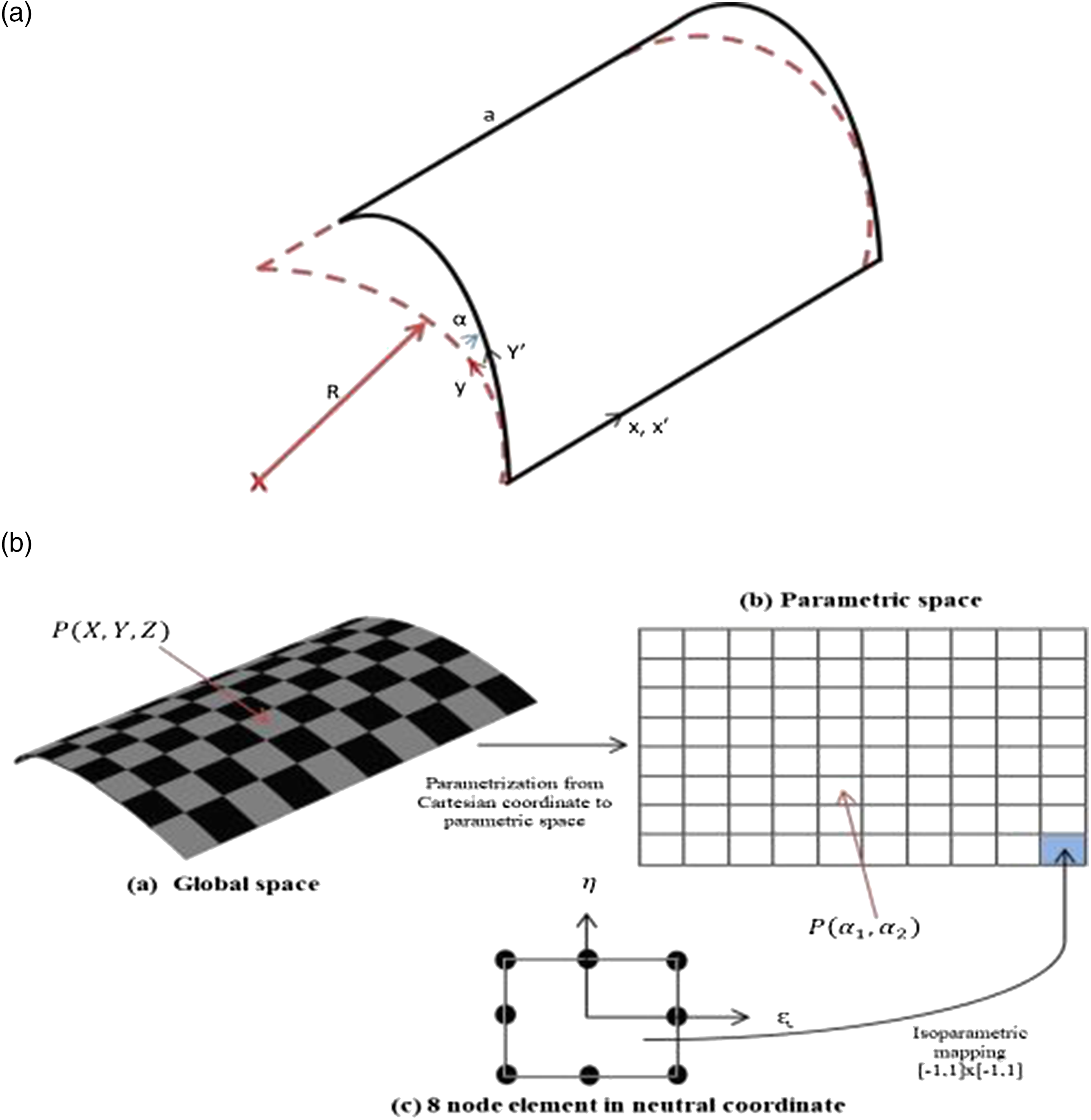
2.2.1. Geometry of FG-CNTRHC skewed shell structure
The mid-surface of the shell surface can be described in terms of the position vector as
The tangent to the isoparametric curves (Sα1 and Sα2) is
The vector joining two points on the middle surface (α1, α2) and (α1+d α1, α2+d α2) is given as
The scalar product of ds is
Defining
As Lame’s parameters or measure numbers that are fundamentals for the understanding of curvilinear coordinates
Because α1 and α2 are the independent coordinates
The unit tangent vectors to the isoparametric curve Sα1 and Sα2 can be expressed, respectively, as
Subscripts 1 and 2 in r1 and r2 indicate the derivative with respect to α1 and α2, respectively. The unit normal vector to the tangent plane at any point on the reference surface can be expressed as
The normal curvatures of the shell mid-surface can be expressed as
2.2.2. Isoparametric mapping
The shell mid-surface in the rectangular Cartesian coordinate system has been mapped into the parametric space (α1, α2), and the mid-surface in the parametric space has been divided into the required number of quadrilateral elements or sub-domains. The reference coordinates (ξ, η) map the quadrilateral elements in the curvilinear coordinates (α1, α2), that is a square as shown in Figure 2(b). Any point within an element in the parametric space has been approximated by the isoparametric mapping.
Hence, the curvilinear coordinates (α1, α2) of any point within an element may be expressed as
The displacement components on the shell mid-surface at any point within an element is determined as
2.2.3. Strain–displacement relationship
The five strain components of a curved shell structure may be expressed as
2.2.4. In-plane strain–displacement relation
The strain components on the mid-surface of the shell element are
By using the 8-noded isoparametric shell element, the displacement component on the shell mid-surface at any point within an element can be expressed as
According to Koiter’s shell theory, the mid-surface strains and curvatures may be expressed in terms of field variables as
By using 8-noded isoparametric shape functions, the strain components at any point on the shell mid-surface can be expressed as
2.2.5. Transverse shear strain displacement relation
According to the First order shear deformation theory (FOST), the transverse shear strain vector of a doubly curved shell element is determined as
The ABD can be written in following integral forms
The shear correction factor is taken 5/6 times in the present analysis, and the shell structure is divided into ‘n’ number of layers as shown in Figure 3. The elements of the ABD matrix are mentioned below (a) Shell element in Cartesian coordinates and (b) functionally graded layer distribution in the thickness direction.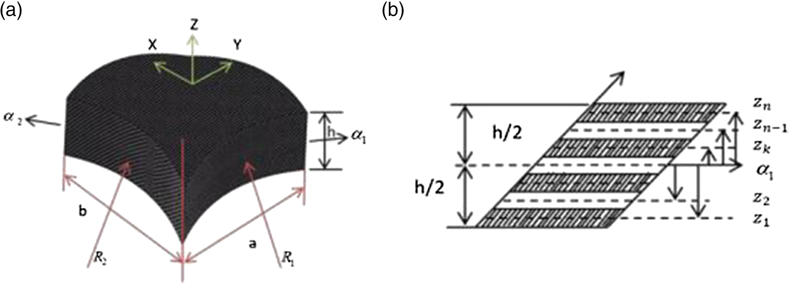
The transformed stiffness matrix is denoted by
The elemental transverse shear stiffness matrix
The external force vector
2.2.6. Determination of stiffness under hygrothermal condition of FG-CNTRHC skewed shell structure
The in-plane strains due to the hygrothermal condition (Ram and Sinha, 1992) can be determined as follows
The transformed hygrothermal stiffness matrix is denoted by
2.2.7. Effective element stiffness matrix of the FG-CNTRHC skewed shell structure
The effective stiffness matrix of the element under the hydrothermal conditions can be expressed as
The elemental dynamic equation can be written as
The elemental mass matrix
The Rayleigh damping model is applied for skew FG-CNTRHC structures to calculate the damping matrix for higher degrees of freedom (Chowdhury and Dasgupta, 2003). The damping matrix [C
d
] can be calculated as
The eigenvector of the system is denoted by
Frequency response analysis
The global equation of motion can be written as
The frequency-dependent dynamic response can be obtained as follows
3. Results and discussions
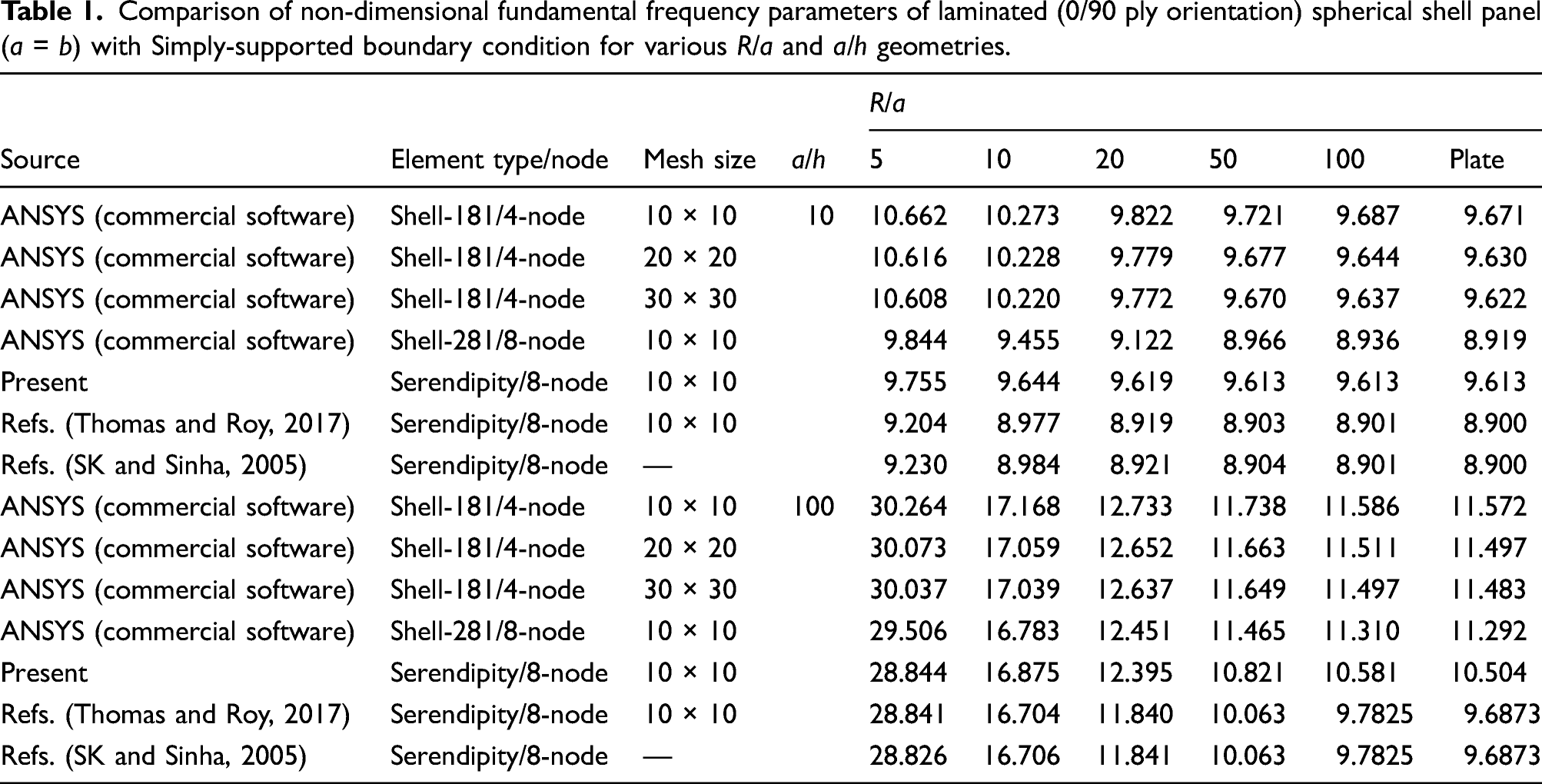
Comparison of non-dimensional fundamental frequency parameters of laminated (0/90 ply orientation) spherical shell panel (a = b) with Simply-supported boundary condition for various R/a and a/h geometries.
3.1. Material properties of NCs and FG-CNTRHC materials
Strength of materials formulation has been used for determination of material properties of the FG-CNTRHC. The carbon fibre volume fraction and the fibre orientation are graded in the thickness direction of the shell using the power law index as shown in Figure 4(a) and (b). The basic constituents of such FG-CNTRHC material system are mentioned in Table 2. It is observed that the higher CNT volume fraction gradually increases the longitudinal material property of the FG-CNTRHC shell as shown in Figure 5(a) which is reinforced by graded carbon fibre 30%–60% in the thickness direction. The elastic property C12 increases gradually up to its maximum value then decreases slightly, may be because of the poison ratio, whereas C23 increases throughout along the thickness direction of the skewed shell which are shown in Figure 5(b) and (c). Value of C22 increases as the volume fraction of carbon fibre increases but C55 slightly increases then decreases along the thickness direction of the skewed shell as shown in Figure 5(d) and (e). It is clear from Figure 5(a)–(e) that the CNT volume fraction may enhance the elastic properties significantly. The smooth increment in the elastic properties of such FG-CNTRHC skewed shell is expected to avoid delamination of the fibres because of the mismatch in the elastic properties. Variation of (a) carbon fibre orientation and (b) carbon fibre volume fraction in the thickness direction of the skewed shell. Basic constituents of functionally graded carbon nanotubes reinforced hybrid composite material system (Kundalwal and Ray, 2011). Variation of (a) C11, (b) C12, (c) C23, (d) C22 and (e) C55 in the thickness direction of the skewed shell.


Based on the above obtained material properties, FE modelling and analysis of FG-CNTRHC skewed shell structure is made by considering 10 × 10 elements (which is decided after convergence studies of displacement and natural frequency). To obtain time and frequency responses, a 16 layered skewed shell structure with ply orientation (0°–90°) having 0.25 mm thickness of each layer is considered for analysis of such FG structures under different hygrothermal conditions. The parametric study has also been carried out on such structure with varying CNT volume fraction into polymer, carbon fibre volume fraction in FG-CNTRHC, power law index, R/a and a/h. Based on the above considerations, various results have been obtained which are presented in the following subsections.
3.2. Maximum displacement and settling time of FG-CNTRHC–based skewed shell structure
The dynamic analysis is carried out for the FG-CNTRHC–based skewed shell structure under uniformly distributed load with the following simply-supported (SSSS) boundary conditions
The effect of the power law index (such as k = 0.2, 1 and 2) and CNT volume fractions (such as 0, 4 and 8) have been observed. In the present study, the skewing shell panel has been subjected to an impulse load of 10 N at the centre for a duration of Variation of transverse displacement with CNT volume fraction for different power law indexes of the FG-CNTRHC–based skewed (a) α = 30o, (b) α = 45o and (c) α = 60o cylindrical shell. Note: FG-CNTRHC: functionally graded carbon nanotubes reinforced hybrid composite; CNT: carbon nanotube. First three non-dimensional natural frequency parameters 
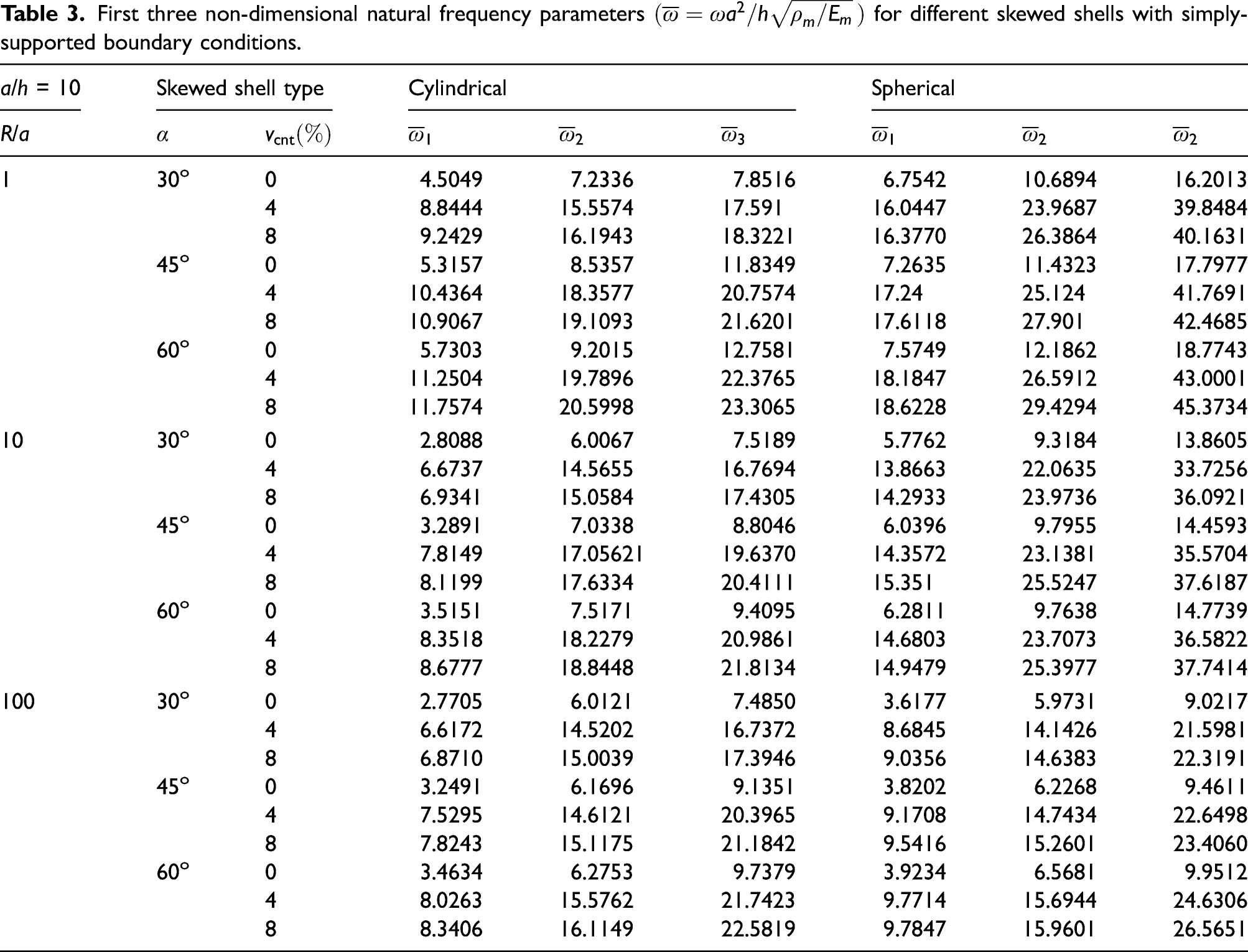
The skewing angle increases the stiffness of the shell structure because of the reduced surface area which can be seen in Figure 7(a) and (b). The skewing angle has dominant impact on the structural stiffness in comparison with the damping, where skewing of the structure needs to be done with a better skewing angle value without distorting the structure, and it is clear from the results that Time responses of FG-CNTRHC skewed (a) cylindrical shell due to impulse load for different skewing angles, (b) spherical shell system due to impulse load for different skewing angles, (c) cylindrical shell due to impulse load for different CNT volume fractions and (d) spherical shell system due to impulse load for different CNT volume fractions. Note: FG-CNTRHC: functionally graded carbon nanotubes reinforced hybrid composite; CNT: carbon nanotube.
3.3. Frequency response analysis of FG-CNTRHC skewed shell structure under hygrothermal conditions
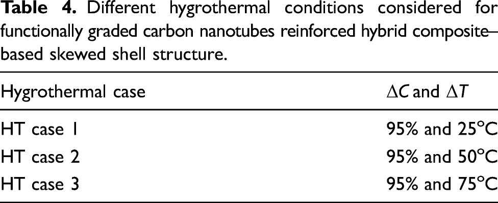
Different hygrothermal conditions considered for functionally graded carbon nanotubes reinforced hybrid composite–based skewed shell structure.
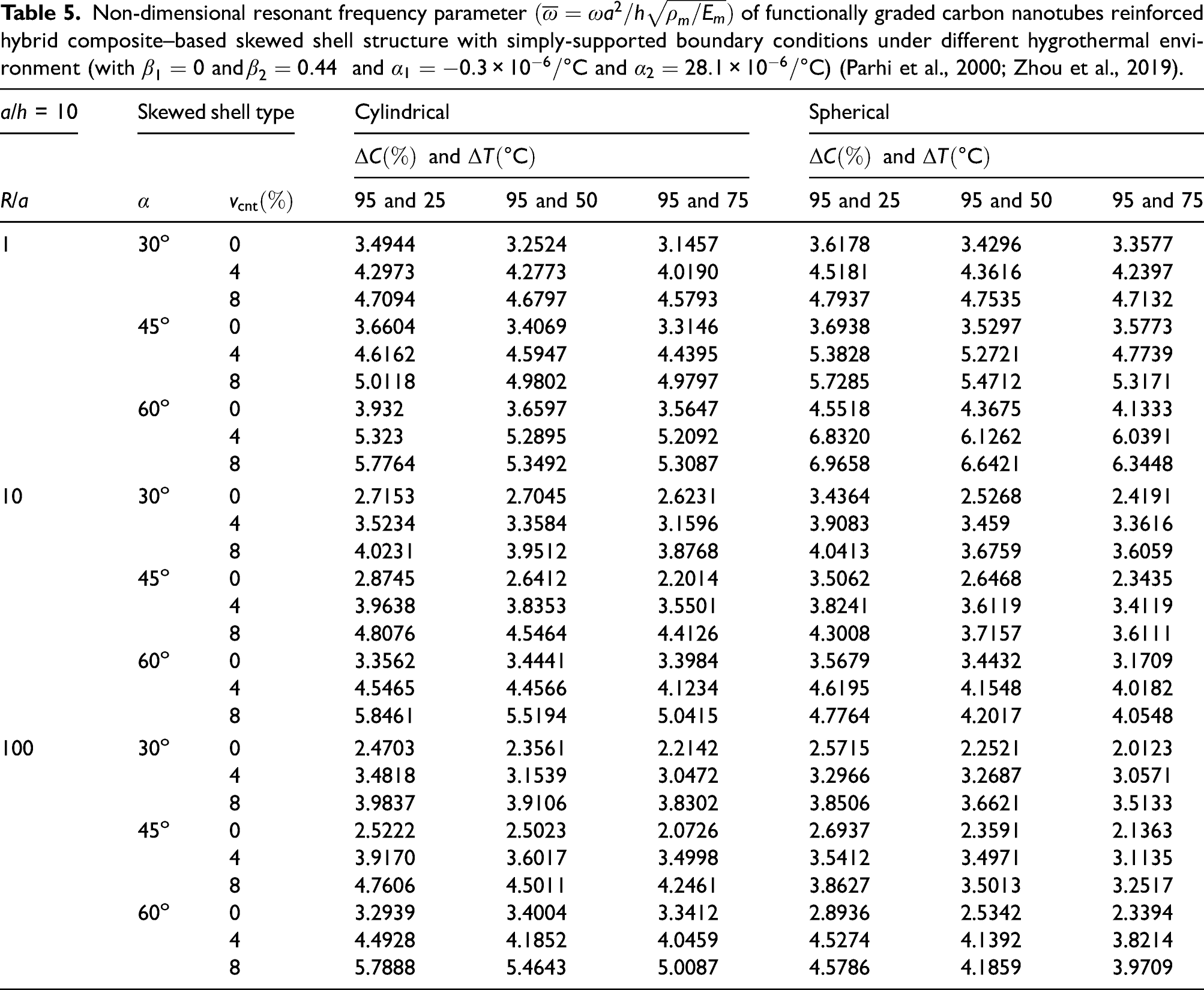
Non-dimensional resonant frequency parameter
To study the hygrothermal effects on transverse displacements at the midpoint of the skewed shell and its resonant frequencies, the frequency response analysis of the simply supported cylindrical and spherical skewed shell structure is carried out for three different hygrothermal cases by considering 8% CNT volume fraction.
A point load of 10 N is applied in the transverse direction at the mid-node of the structure to perform the frequency analysis under different hygrothermal cases for different CNT volume fractions. A certain type of geometry (thick and deep shell i.e. R/a = 1 and a/h = 10) has been analysed, and the frequency response is obtained as shown in Figure 8(a) and (b). The effect of different hygrothermal cases is seen with the clear variation in the curves depicting the decrease in resonant frequency of such structure in hygrothermal case 3 because of high temperature and moisture concentration. Clearly, because of the hygrothermal environment, the induced stresses and strains are affecting the structural strength which results in increase of absolute displacement and decrease in the resonant frequencies. Different geometries (such as R/a = 1, 10 and 100 with a/h =10 and 100) are considered, and the frequency analysis is performed under all three hygrothermal cases so as to check the impact of different CNT volume fractions on such FG-CNTRHC skewed shell structures. The comparative study for the resonant frequency parameter is also carried out for different FG-CNTRHC skewed cylindrical and spherical shell structures as shown in Table 5. The frequency parameter decreases for the higher R/a and a/h geometries as the shell structure becomes shallow and thin. The skewing angle (α = 45°) significantly increases the structural stiffness of the structure which results in higher resonant frequencies. Frequency responses of functionally graded carbon nanotubes reinforced hybrid composite skewed (a) cylindrical and (b) spherical shell system under different hygrothermal conditions.
3.4. Impulse-induced transient response analysis of FG-CNTRHC skewed shell structure under hygrothermal conditions
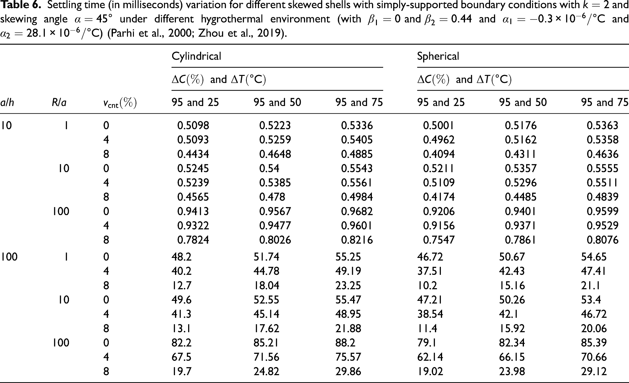
The transient response analysis is carried out for the simply supported cylindrical (R2 > 1030) and spherical (R1 = R2) skewed shell on square base (a = b) under impulse load. The settling time is obtained for the comparative study of the vibration damping of such shell structures. A thick and deep (R/a = 1 and a/h = 10) type of geometry is considered for skewed shell structures to obtain the transient response which is shown in Figure 9(a) and (b). The effect of different volume fractions of the CNT at 45o skewing angle for Hygrothermal (HT) case 1 is performed thereafter from the obtained transient responses. It is clear from the obtained responses in the figures that higher volume fraction of CNTs improves the damping of such structures by lowering settling time. The comparative study also encompasses different geometries (viz. R/a = 1, 10 and 100 with a/h = 10 and 100) for the transient response analysis under all three hygrothermal cases as shown in Table 6. The higher R/a and a/h values make the structure shallow and thin hence exhibit higher settling time. It is clear from the results that CNT improves the damping of the FG-CNTRHC skewed cylindrical and spherical shell structures. Time response of FG-CNTRHC skewed (a) cylindrical and (b) spherical shell system under hygrothermal case 1 for the different volume fractions of CNTs. Note: FG-CNTRHC: functionally graded carbon nanotubes reinforced hybrid composite; CNTs: carbon nanotubes. Settling time (in milliseconds) variation for different skewed shells with simply-supported boundary conditions with 
4. Conclusions
The vibration and damping analysis has been carried out numerically for different FG-CNTRHC skewed shell structures under hygrothermal conditions. The Mori–Tanaka scheme is used along with strength of materials method to obtain the effective elastic properties of FG-CNTRHC composite materials. The CNT is incorporated into such HC to avoid the delamination of the structure under the complex loading conditions. Furthermore, the FG distribution of carbon fibre volume fraction and its orientation in the thickness direction is varied by using the power law to strengthen the structure. The dynamic analysis is carried out by using such elastic properties of FG-CNTRHC composite materials for different skewed shell structures under hygrothermal conditions. The geometry of shell is defined by using an oblique coordinate system with a tangent to the edge for skewing the structure and said skewed shell structure is discretised by considering an eight-noded shell element for the FE analysis. Increasing the skewing angle causes a reduction in the surface area of the shell structure which leads to an increase in the material concentration, thereby resulting in higher natural frequencies. The stresses induced because of hygrothermal conditions are incorporated into dynamic analysis by calculating the effective stiffness of such skewed shell structures. The transient responses indicate that the CNT is more influential than carbon fibres in the shell structure because the CNT possess better damping properties under different hygrothermal conditions. Significant decrease in the settling time is observed by addition of CNTs in the hybrid FG skewed shell structure. The effect of thermal and moisture concentration results in increase in the absolute amplitudes of such structures. The frequency responses of such structures depict that CNTs have significant impact on the absolute amplitude in comparison with the first resonant frequency. So, it is evident that the inclusion of the CNT may improve the damping property of the FG-CNTRHC skewed shell structure under the hygrothermal conditions. It can be concluded that for hygrothermal condition–based applications, the CNT can play a vital role to achieve better dynamic responses by mitigating vibrations quickly for FG-CNTHRC skewed shell structures.
Footnotes
Declaration of conflicting interests
The authors declared no potential conflicts of interest with respect to the research, authorship, and/or publication of this article.
Funding
The authors disclosed receipt of the following financial support for the research, authorship, and/or publication of this article: The authors kindly acknowledged the IMPRINT cell of the Ministry of Human Resource Development (MHRD) and Department of Science and Technology (DST), Government of India, for a project grant (No. 6292) under which the research work was carried out.

Appendix 1
The Jacobian is expressed as