
Abstract
To improve the efficiency of conventional isolation trench and lighten the impact of the excavation on neighbor buildings, a novel high damping isolation trench is proposed. The viscoelastic braces equipped in the high damping isolation trench can dissipate the energy of ground-borne vibration while providing supporting force to ensure the stability of the soil on both sides. According to two actual ancient buildings, two types of high damping isolation trenchs with the plane shape of U and L are designed to solve the potential damages caused by long-term train-induced vibration. First, three-dimensional finite/infinite models based on these two buildings are established, respectively. Then, the energy dissipation characteristics are obtained by experiments. Through calculation, the control effects of the high damping isolation trenchs for these two buildings are investigated. The results indicate that the viscoelastic braces possess high energy dissipation capacity. After setting the high damping isolation trenchs around the structures, even at a small excavation depth, the acceleration and velocity responses of the two buildings are reduced significantly. Furthermore, the selected U-shaped and L-shaped trenches also show superiority compared with the conventional linear-shaped trench in this project.
1. Introduction
Man-made vibration arisen from different sources is an increasing important issue. The long-term vibration can affect the serviceability of buildings and also lead to fatigue damage even at low amplitudes. Particularly when a structure exists some internal defects, such as the ancient building, these defects can be continually magnified and affect structural safety. Applying a trench barrier between the source and the protected building has long been considered as an accepted strategy. Many researches have evaluated its feasibility by field tests and numerical analyses (Adam and Von Estorff, 2005; Connolly et al., 2013; Coulier et al., 2015; Garinei et al., 2016; Korkmaz et al., 2011). According to these research studies, it can be concluded that a large depth is essential for a trench to achieve effective isolation. However, for many projects, this requirement is usually unrealistic in practice.
There have been many attempts to address this shortcoming, of which adding filling material is a frequently used measure. Itoh et al. (2005) tested the effects of barriers with aluminum and expanded polystyrol, and Lu and Tan (2011) investigated the performance of concrete and wood plane infilled trenches. Ju and Li (2011) and Kumar et al. (2014) all studied the function of water saturated trench barriers. Mahdavisefat et al. (2018) demonstrated the superiority of a novel infill isolation trench utilized sand–rubber mixture (SRM) which has high absorbing capacity and can be constructed easily. Kumar and Ghosh (2020) studied the feasibility of a vibration screening system that applying the natural material bamboo.
Some researchers have noticed the benefits of using geofoam barriers to mitigate ground vibration (Murillo et al., 2009; Zoccali et al., 2015). Based on their works, Majumder et al. (2017) replaced the continuous geofoam with intermittent geofoam (IF) and found that the IF infilled trench can achieve a more significant reduction in amplitude. Pu and Shi (2020) propose a new periodic trench which can attenuate surface waves effectively in a certain frequency domain.
Furthermore, there also exist some other methods. Jayawardana et al. (2019) evaluated the possibility of using multiple trenches, and Baziar et al. (2019) proposed a double geofoam barrier. Chen et al. (2011) implemented a new measure considered the wave impeding barrier, which can obstruct the wave transmission and achieve a satisfactory mitigation. Esmaeili et al. (2014) proposed a V-shaped trench, and Zakeri et al. (2013) presented a step-shaped trench, which both can perform better than the standard rectangular-shaped one.
The previous research studies promote the isolation trench becoming a mature technique. However, the main focus of the above works has been on attenuating the ground-borne vibration. Even those studies involving the dynamic responses of the protected structure are mostly limited to two-dimensional model. As a result, the influence of the trench’s plane shape is ignored. Meanwhile, the excavation of isolation trenches will inevitably destroy the stability of soil. If the structures beside the trench that are inherently defective, even a small depth of excavation will pose threats to their safety. Therefore, neither the efficiency nor the security can be neglected when designing a reliable wave barrier.
In this study, a novel HDIT with viscoelastic braces is proposed to improve the efficiency of conventional isolation trench and guarantee the stability of the surrounding soil. Two types of HDIT with U shape and L shape are designed to reduce the damage of two ancient buildings caused by train-induced vibration. And the three-dimensional finite/infinite analysis is conducted to investigate the screening effect of the proposed HDIT.
2. Introduction of the vibration mitigation project
2.1. Construction and mechanism of the HDIT
The novel high damping isolation trench comprises a trench, a pair of retaining structure, and several viscoelastic braces as presented in Figure 1. The cross-sectional profile of the trench arranged between vibration source and the protected building to block wave propagation can be rectangle or other shapes. On each side of the trench, the retaining structure is applied to maintain the stability of the surrounding soil after excavation. The viscoelastic braces installed inside the trench can increase the energy dissipation capacity as well as provide supporting force to the soil on both sides. The main elements of the viscoelastic braces are shown in Figure 1. There is a viscoelastic cushion located inside the outer steel cylinder and tightly contacted with the steel plates used for force transmission. Through adjusting the position of the steel plate and tightening the high-strength bolts arranged along the circumference, the viscoelastic cushion can be preloaded to obtain a suitable initial stiffness and is allowed to deform toward each side. Construction of the high damping isolation trench.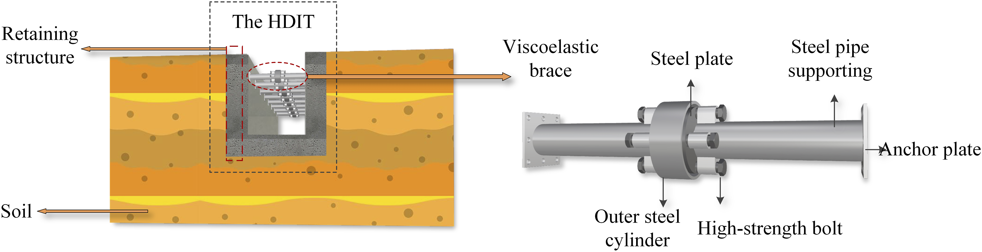
The novel HDIT combines the advantages of blocking wave propagation and consuming vibration energy. First, when the excitation generated by external source transmits to the HDIT, the direction change of wave will occur at the interface between soil and the trench because of reflection and scattering, which is similar to the conventional isolation trench. Besides, the vibration acted on the HDIT can make the viscoelastic cushion produce compressive deformation which, in turn, dissipates energy. This can help the HDIT to be superior to the ordinary isolation trench in the aspect of vibration mitigation. On the other hand, the safety of the soil and the adjacent structure after the excavation can be ensured by installing the viscoelastic braces. Specifically, when the retaining structure undergoes large deformation because of some external factors, the viscoelastic cushion in the brace will come into close contact with the outer steel cylinder as the rapid increase in compression. Thus, the large stiffness can be produced to preserve the stability of the soil. Consequently, the novel HDIT is suitable for some engineering problems that have restriction on the site condition.
2.2. Introduction of the project
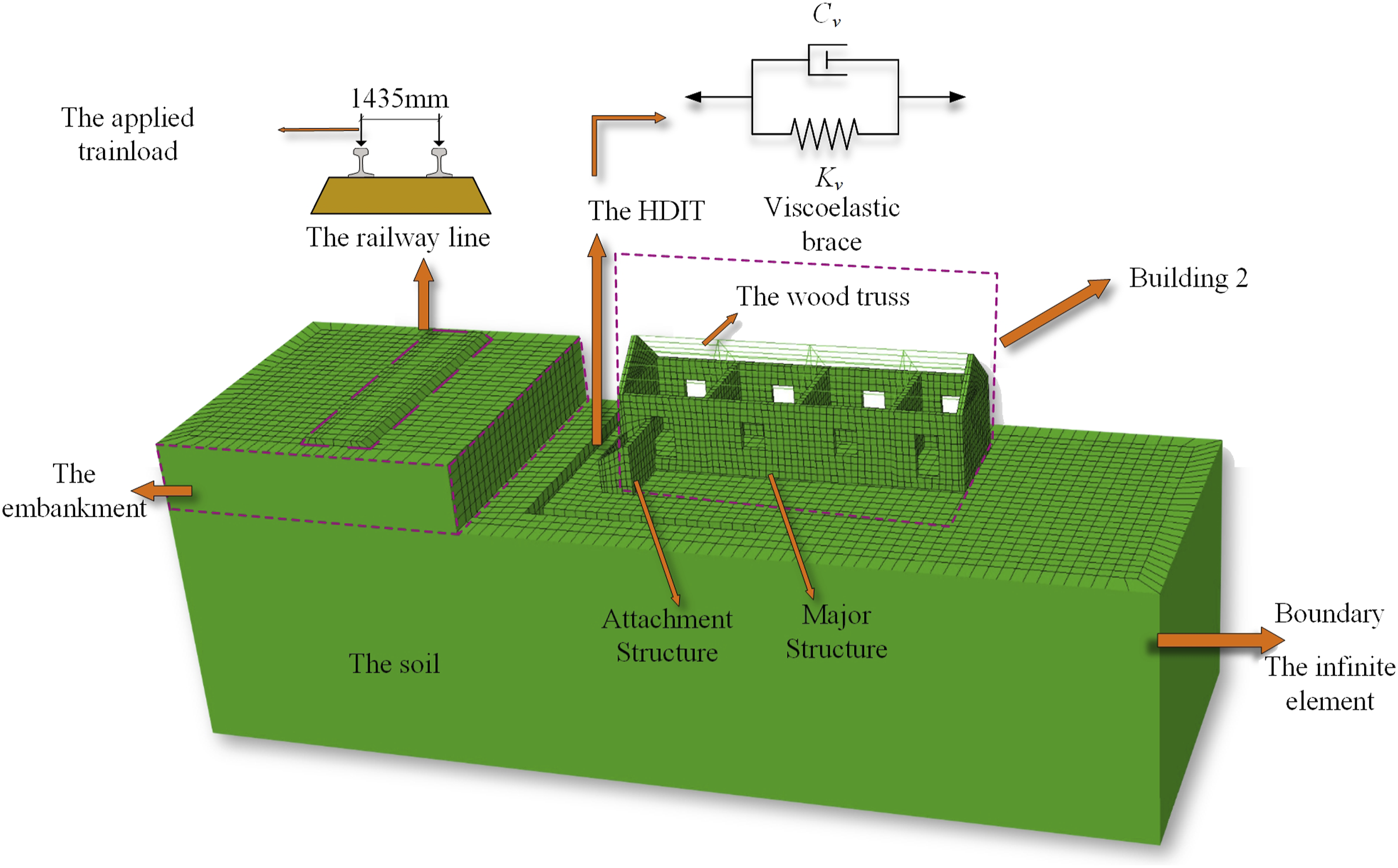
To evaluate the potential of the HDIT, an actual historical architecture preservation project located on the southeast coast of China is selected as an example, which includes two single-story masonry structures built over 100 years. As shown in Figure 2, the building 1 has a regular square plane shape and located at a distance 8 m from the centerline of the railway track. The construction of building 2 is more complicated than building 1. Apart from the rectangular-shaped major structure, there also exits an attachment structure built afterward. Meanwhile, on the top of the major structure of building 2, there is a wooden truss erected to pave roof and increase the lateral stiffness. According to the site investigation, the distance between the north side of the building and the centerline of railway is 8.5 m. The dynamic characteristics of the two buildings can be obtained by modal analysis. It can be found that the first three-order frequencies of building 1 are 8.62 Hz, 9.86 Hz, and 9.94 Hz, whereas those of building 2 are 8.63 Hz, 11.03 Hz, and 12.6 Hz. Schematic plan of the project.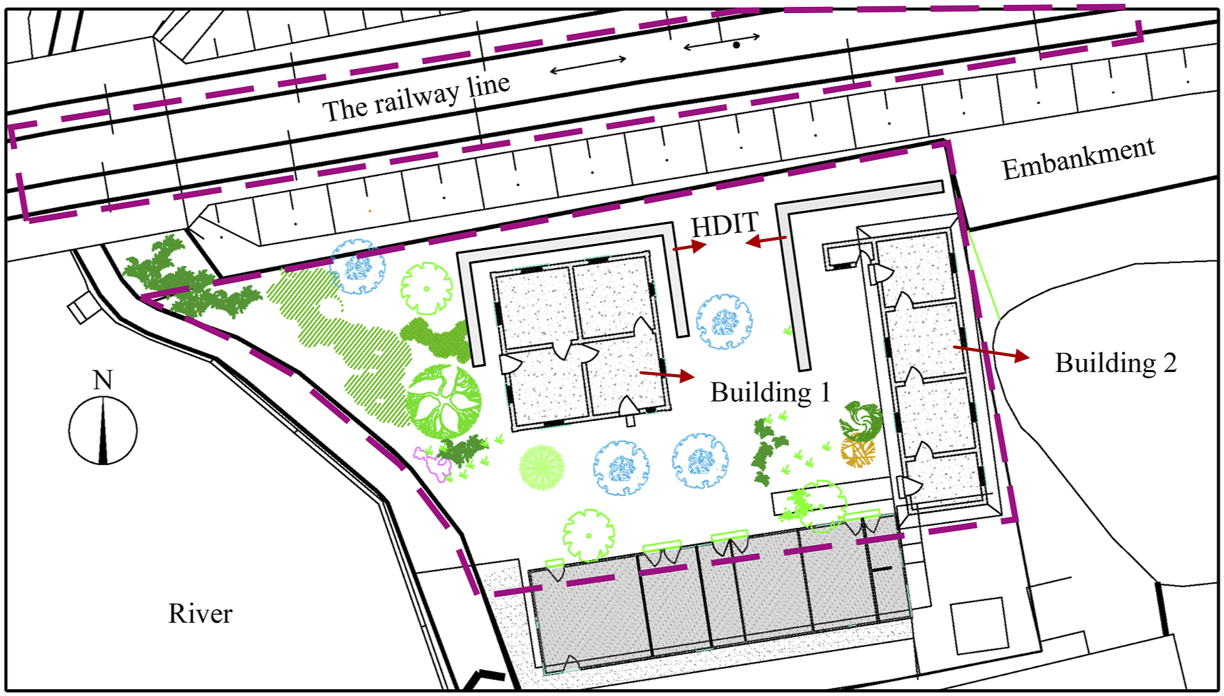
Because of the adjacent relationship with the railway line, strong vibration can be felt around the two buildings when a train passes by, and distinct cracks can be observed on them. However, because of the limitation of site condition, the traditional isolation trench is difficult to construct and maintain in practice. Previous studies (Adam and Von Estorff, 2005) indicated that the traditional isolation trench requires a sufficient depth to achieve a high level of screening. However, the adjacent structure on each side is too close to the trench so the large excavation depth will unavoidably cause adverse effect. On the side of the buildings, the stress relaxation of the soil may lead to uneven settlement of the foundation and accelerate the destruction. On the side of the railway line, the stability of the embankment slope will be affected, thus threatening the train operation safety. These problems can be alleviated by applying the proposed HDIT. Because of the supplemental energy dissipation produced by the viscoelastic brace, the control effect of the trench can be improved, thereby avoiding excessive excavation depth.
2.3. The design of the HDIT
The configuration and dimension of each HDIT utilized in this project are eventually determined after analyzing the previous parametric studies as well as considering the impact of excavation. The HDIT of building 1 is introduced with a U shape, which surrounds the three sides of the structure that are susceptible to vibration, as shown in Figure 2. The length of the trench parallel to the railway line is 12 m and that perpendicular to the railway line is 6 m. The distance from the centerline of the HDIT to the north side of building 1 is 1.5 m. The HDIT of the building 2 is L-shaped, as shown in Figure 2, whose length parallel to the railway line is 9.3 m and perpendicular to the railway line is 9.7 m. The distance from its centerline to the structural edge is 2 m. The previous parametric studies (Adam and Von Estorff, 2005) indicated that the effective depth and width of isolation trenches need to vary between 0.6 to 1.33 and 0.1 to 0.5 times Rayleigh wavelength, respectively. According to this, in this project, the appropriate depth of the trench after calculation is between 1.3 m and 3 m, and the width is between 0.23 m and 1.2 m. Meanwhile, taking the construction safety and installation requirements of the viscoelastic braces into account, the width and depth of the two HDITs are both taken as 0.6 m and 1.3 m.
The viscoelastic braces installed in the HDITs of these two buildings all have the same specification and are arranged at 1 m interval. The viscoelastic cushions used in these braces are 70 mm in diameter and 35 mm in thickness. Besides, the diameter of the steel cylinder outside the viscoelastic cushion is 80 mm; hence, a 10 mm of clearance is reserved between the cylinder and the cushion. According to the incompressibility assumption (Xu et al., 2013a), the viscoelastic cushion is free to deform within 10 mm. However, when the displacement exceeds the permissible value, a large stiffness will appear, and the further deformation of the cushion will be limited because of the contact between the cushion and the inner wall of the cylinder. In a real installation, the bidirectional motion capability of the viscoelastic braces can be ensured through adjusting the high-strength bolts to preload the cushion by 2 mm.
To implement the HDIT into practice, some important issues also need to be considered. First, the deformation of the retaining structures and its capacity to maintain the soil stability should be rigorously calculated. Second, the viscoelastic braces are installed after the construction of the trench, and the viscoelastic cushion in it can be convenient to alternate in long-term service. Furthermore, it is vital to set a drainage system at the bottom of the trench, which can effectively prevent the erosion of the retaining system and the viscoelastic braces.
3. 3D model for soil-structure-HDIT
In this section, the 3D finite/infinite element soil-structure-HDIT models based on these two buildings are established in Abaqus. And the structural dynamic responses caused by train-induced excitation are calculated to evaluate the feasibility of employing the HDIT in real project. The models of the buildings 1 and 2 are presented in Figures 3 and 4, respectively. 3D finite/infinite model of building 1. 3D finite/infinite model of building 2.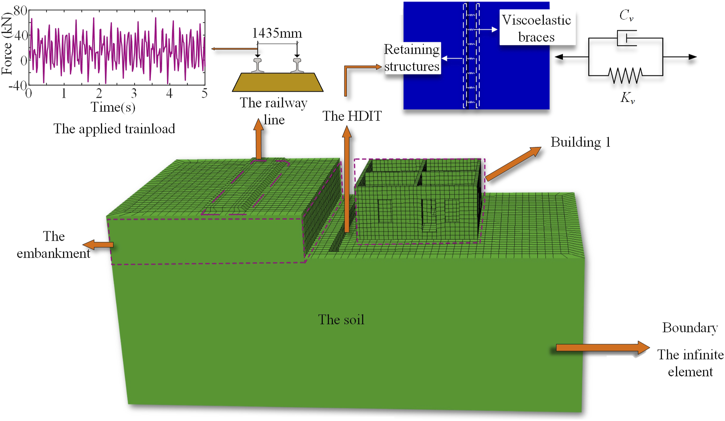
In addition, to demonstrate the rationality of using the U- and L-shaped trenches in this project, other two models are also considered in which the HDIT is introduced with a sufficient long linear-shaped trench. This plane shape is the most commonly used one in previous studies, whereas it is hard to achieve in this project because of the limitation of the site condition. Except for the plane shape, the depth, width, and locations of the linear-shaped trenches are same as the U- or L-shaped trenches designed in this project. And the viscoelastic braces applied in them are all having the same specification and installed at 1 m interval. The details of the linear-shaped trench can refer to Section 2.3.
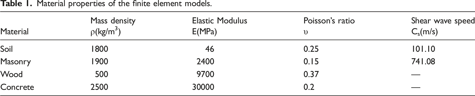
3.1. The soil–structure models and considered parameters
Material properties of the finite element models.
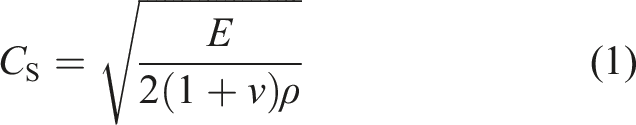
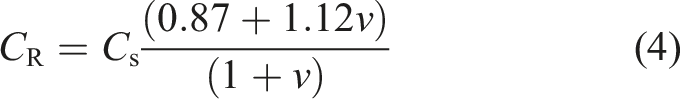
When meshing the models, to make the calculation combined with accuracy and efficiency, an appropriate element dimension g can be expressed by the following equations (2) and (3) (Zerwer et al., 2002)
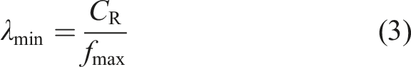
To prevent Rayleigh wave from reflecting at the boundaries and leading to spurious results, it is necessary to set up artificial boundaries to absorb energy. In this study, the continuum 3D 8-node infinite element (CIN3D8) is adopted for analysis, as shown in Figures 3 and 4, which completely wraps the models except for the upper surface. The excitation force of the train can be simulated by applying two rows of load along the railway track, and the time history curve is shown in Figure 3, which is the superposition of harmonic loads in 0–5 Hz, 10–20 Hz, and 20–50 Hz.
3.2. The test and parameters of the viscoelastic brace
The viscoelastic materials have been widely used in several fields, and many researches have conducted to reveal their behaviors (Xu et al., 2010, 2013b, 2017). To assess the material used in this project, a series of tests are carried out on the full-scale specimen of the cylindrical viscoelastic cushion in the HDIT, and the loading device is shown in Figure 5. During the tests, the specimen is subjected to harmonic excitation with different amplitudes and frequencies. All the tests are implemented at an ambient temperature of 6.1°C and under five cycles of deformation. In accordance with the actual situation, proper preloading is applied to the specimen before each test, and the position after the preloading is taken as the initial point of the dynamic loading. Then, typical force–deformation relationships of the viscoelastic are plotted in Figure 6, where the third cycle of the hysteresis loops at the frequency (f) of 2, 5 Hz and the amplitudes (d) of 0.5, 1, and 1.5 mm are shown. Loading device. Hysteresis loops of the viscoelastic cushion: (a) f = 2 Hz and (b) f = 5 Hz.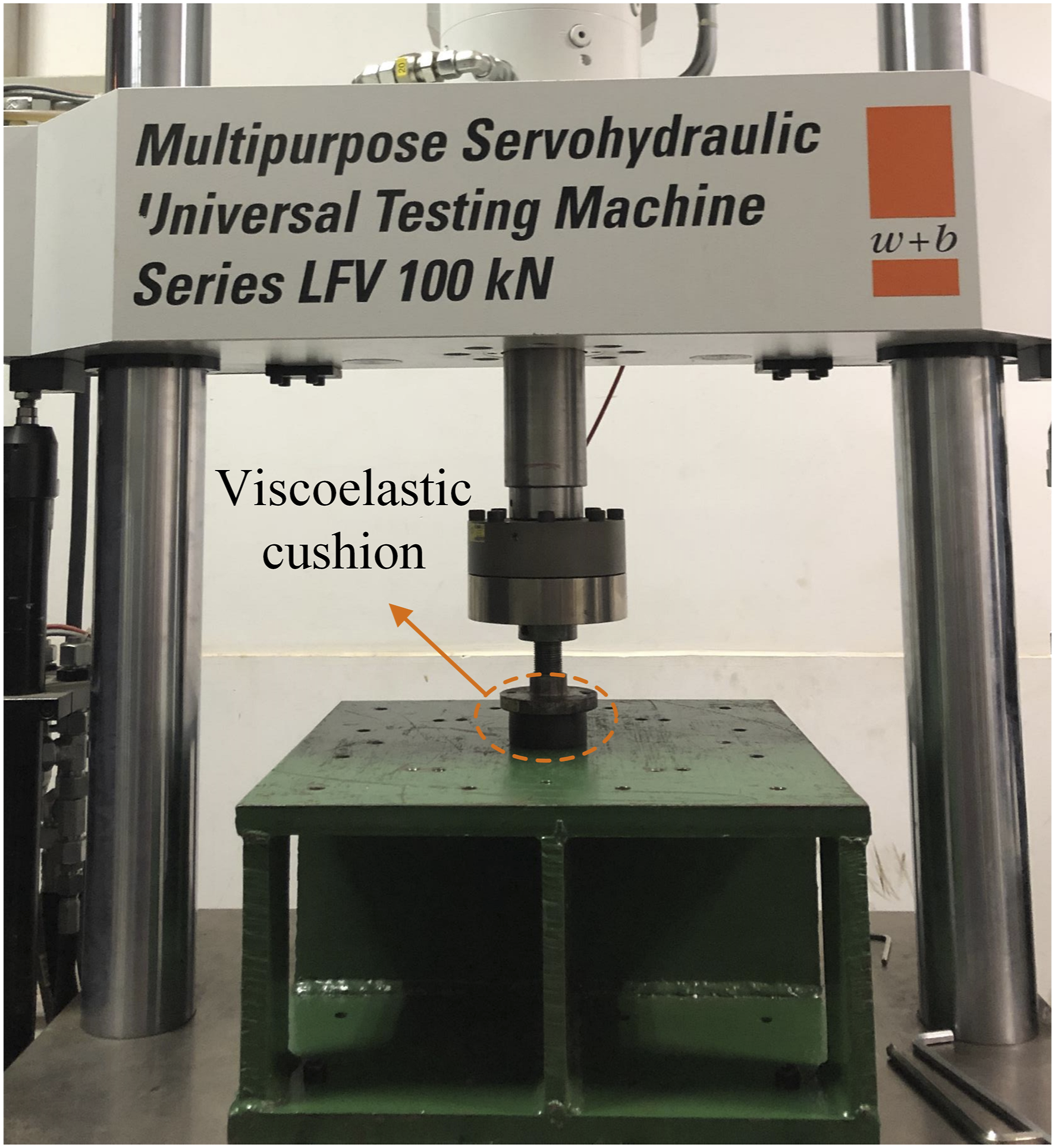
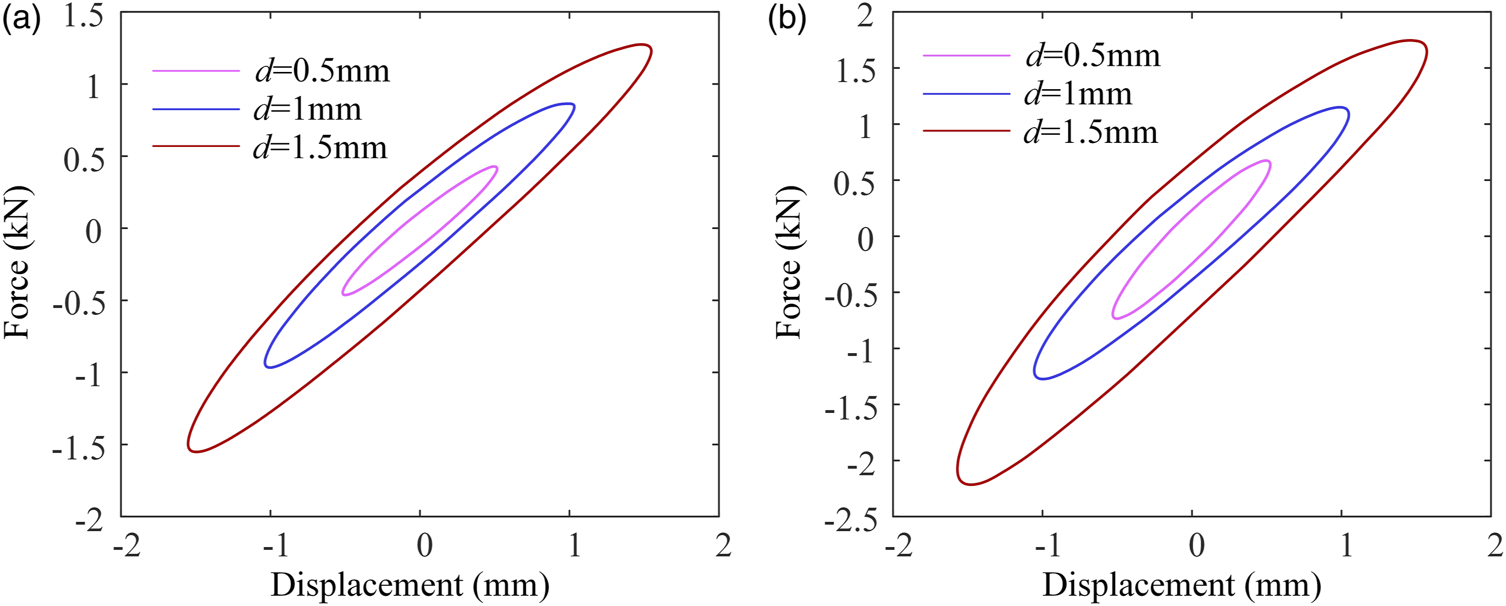
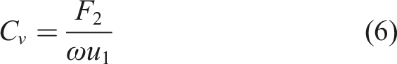
The test results reveal that the viscoelastic cushion have excellent energy dissipation capacity because of the large enclosed area of the hysteresis loops. Meanwhile, as a rate-dependent damping material, frequency has significant effects on its properties. This can be observed from the test results that both the enclosed area and the slope of the hysteresis loop will increase with the increase of the frequencies. However, because of the small amplitudes in this test, the difference of mechanical properties under each amplitude is not obvious. On the other hand, the viscoelastic cushion also performs excellent resilience for the linear and elliptical hysteresis loops in the test. And the deformation of the cushion can be quickly recovered even compressed at high frequencies. Concerning the characteristics of the viscoelastic cushion during the test, the mechanical properties can be described by the equivalent stiffness K
v
and the equivalent damping C
v
based on the classical linear viscoelastic theory (Xu et al., 2011)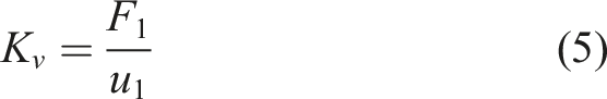
3.3. The arrangement of the measuring points
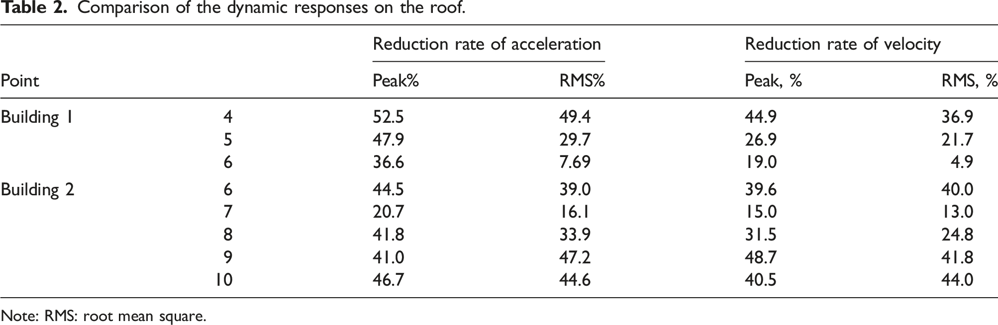
As shown in Figure 7, two groups of measuring points are arranged on buildings 1 and 2, respectively. Besides, two measuring points are also arranged on the top of the attachment structure of building 2. The vibration of the two buildings is quantified through the acceleration and velocity responses at each point, and the reduction of peak and root mean square (RMS) value is used to evaluate the performance of the HDIT. Distribution of measuring points: (a) building 1 and (b) building 2.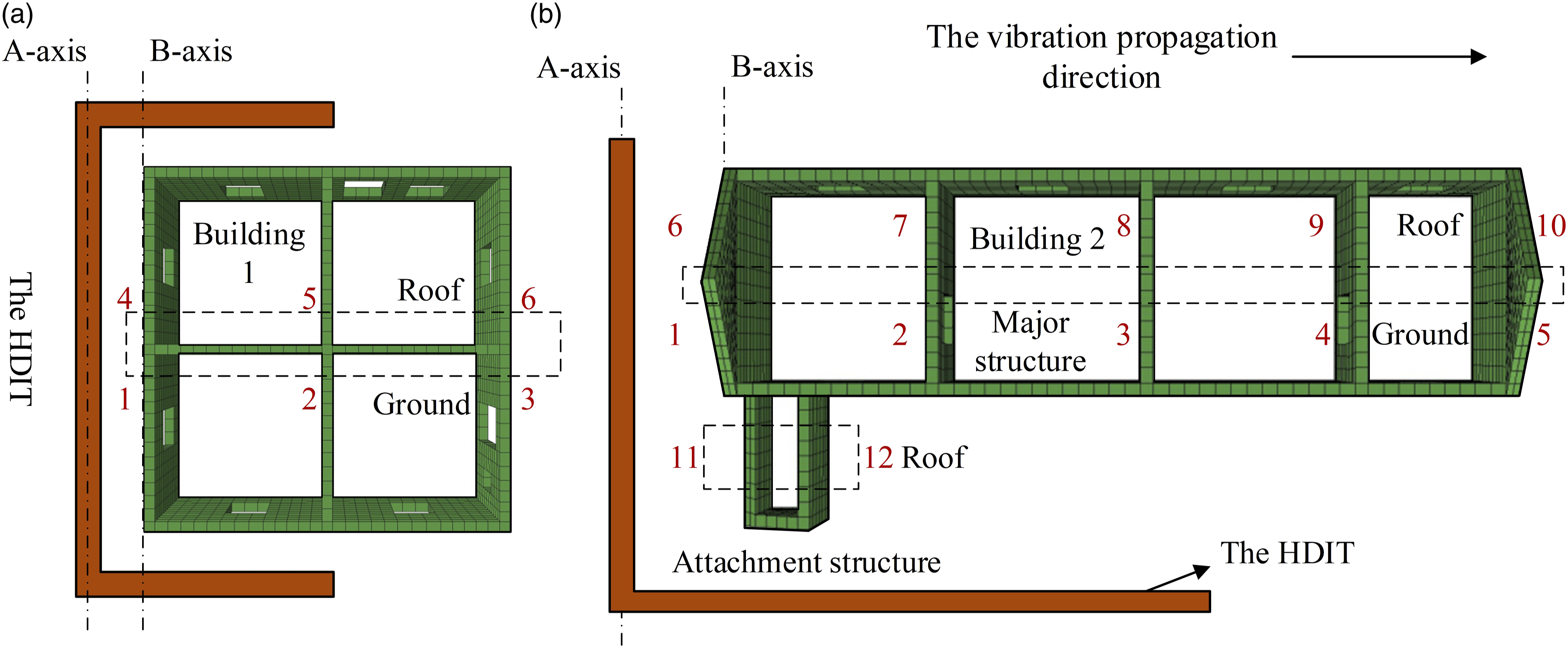
4. Results of dynamic response analysis
4.1. The dynamic responses of building 1
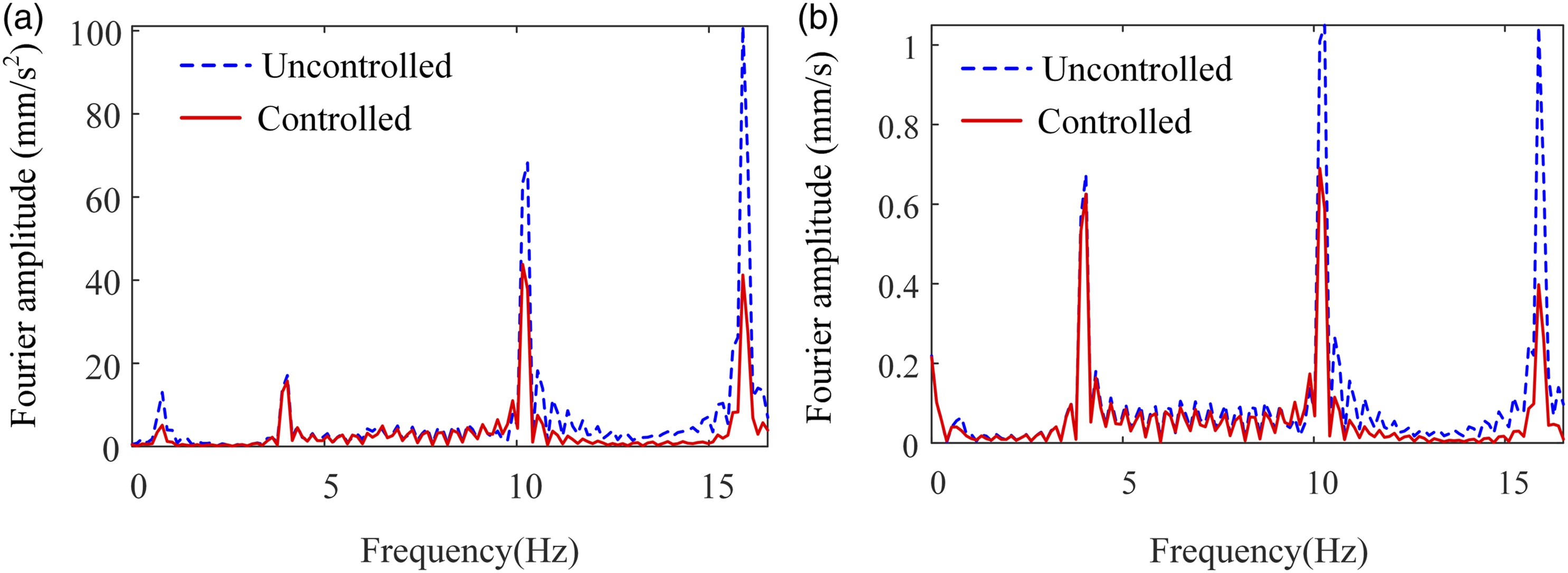
In Figure 8, the horizontal dynamic responses at point 4, which is located on the top of building 1, are compared between the controlled and uncontrolled conditions. And the analysis results of the remaining points on the top of building 1 are summarized in Table 2. It can be concluded that the responses of the structure with the HDIT are remarkably smaller than those without the HDIT both for acceleration and velocity. As shown in Figure 8(a) and (b), the reduction of peak acceleration and velocity values can be up to 52.5% and 44.9%, while that of RMS acceleration and velocity can reach 49.4% and 36.9%. Meanwhile, Figure 9 presents the frequency-spectrum analysis results for the horizontal dynamic responses at point 4. It can be noticed that because of the energy dissipation provided by the HDIT, the vibration whose frequency is close to the structural eigenfrequency and may cause stronger responses can be apparently decreased. Horizontal dynamic responses of building 1: (a) acceleration and (b) velocity. Comparison of the dynamic responses on the roof. Note: RMS: root mean square. Frequency-spectrum analysis results at point 4: (a) acceleration and (b) velocity.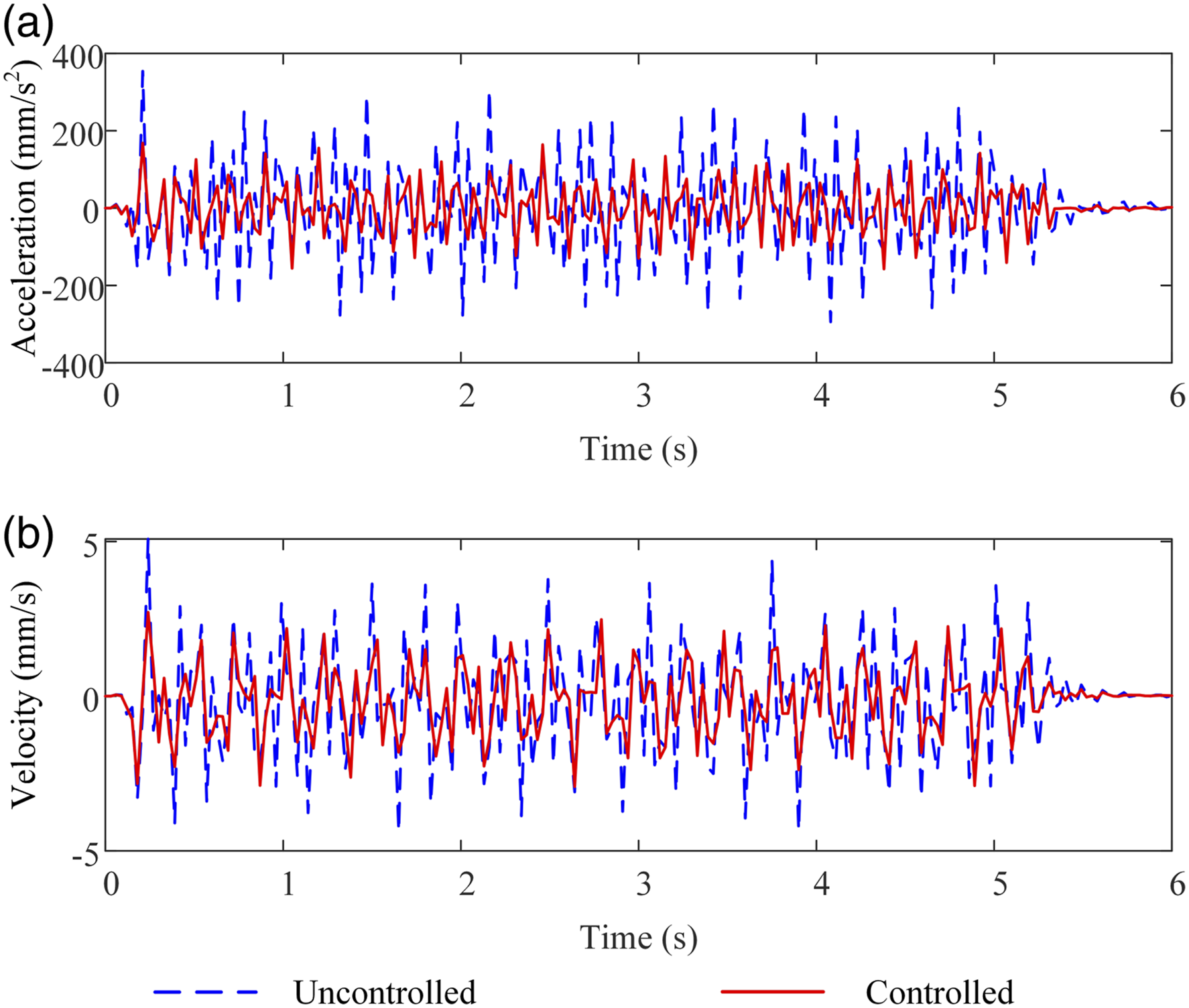
In Figure 10, the horizontal dynamic responses at point 4 are also compared between the conventional isolation trench and the novel HDIT. For the conventional isolation trench, the depth, width, and plane shape are all same as the HDIT; however, the viscoelastic braces inside the trench are removed. It can be seen that the HDIT is superior to the conventional isolation trench for the energy dissipation capacity provided by the viscoelastic braces. As shown in Figure 10(a) and (b), when comparing with structure used the conventional isolation trench, the peak acceleration and velocity responses of the structure applied the HDIT can be further reduced by 47.6% and 31.7%. And the RMS acceleration and velocity also can be decreased by 53.7% and 33.9%. Comparison between the conventional isolation trench and the HDIT: (a) acceleration and (b) velocity.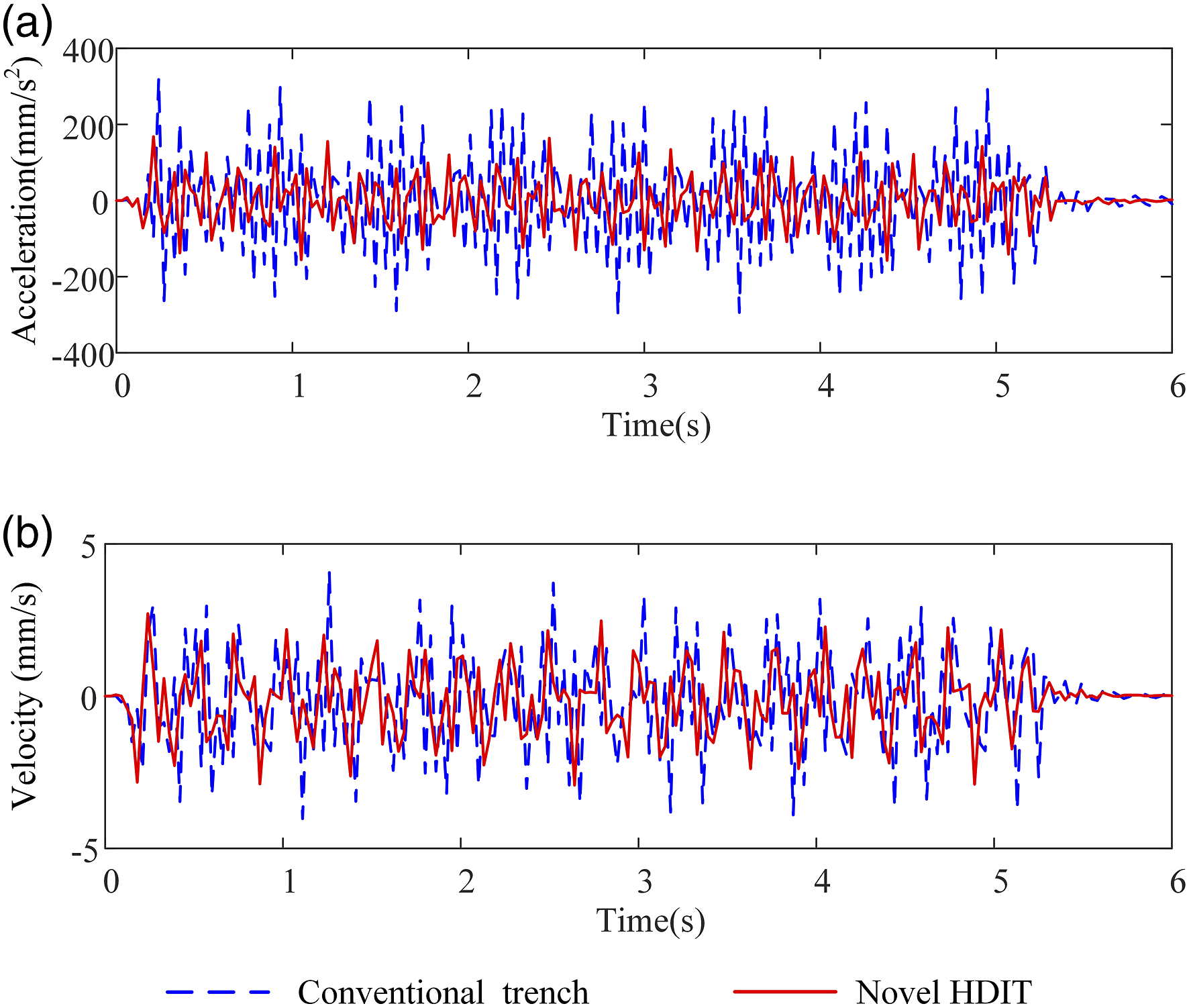
The screening effects of the HDIT at different points on building 1 are depicted in Figure 11, in which the ordinate indicates the maximum responses at each point, whereas the abscissa λD means the ratio of the distance between the point and the B-axis to the length of the building. It is obvious that the value of λD increases with increasing of the distance to the HDIT. According to Figure 11, significant reductions of horizontal dynamic responses can be observed at each point on building 1 because of the application of the HDIT. The maximum reduction rates of peak acceleration and peak velocity are 52.5% and 47.0%, respectively. In addition, because the segment of the trench that perpendicular to the railway line only reaches the middle of the building, and the space between the building and the trench is small, a portion of wave can still bypass the HDIT and continue to affect the structure. It can be an explanation for the low reduction rates at the points 3 and 6 where λD is equal to 1. Nevertheless, from the perspective of the overall structure, the HDIT still performs effectively. Effect of high damping isolation trench at each point of building 1: (a) peak acceleration and (b) peak velocity.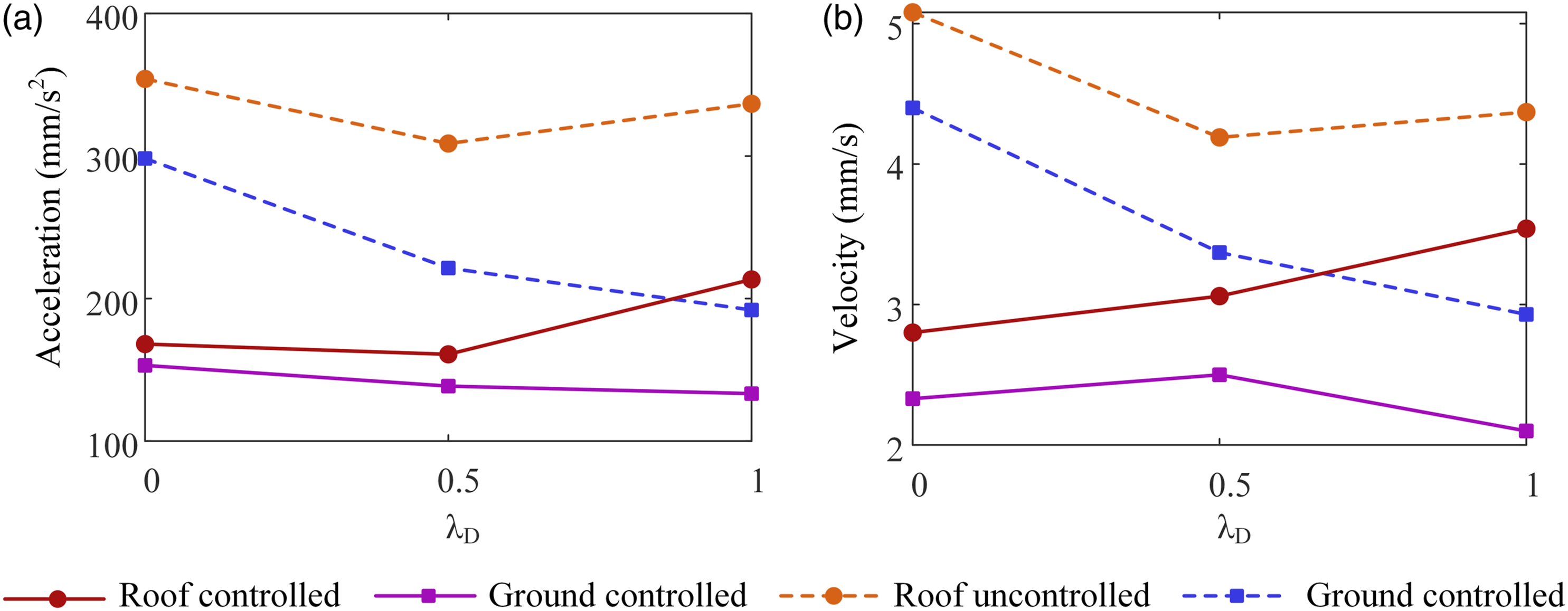
The performance of the HDIT with traditional linear-shaped trench is also obtained, and the responses of different plane shapes are compared here, as shown in Figure 12. From these figures, it can be observed that applying the U-shaped trench, the RMS reduction rates of the horizontal acceleration and velocity at point 4(λ
D
= 0) are both higher than those in the case of using the linear-shaped trench. However, with an increase in the distance away from the HDIT, the screening effects of the linear-shaped trench gradually exceed the U-shaped trench. The main cause for this is because with respect to the U-shaped trench, few vibrations can bypass the ends of the linear-shaped trench with sufficient length. Reduction rates of the root mean square responses on the top of building 1 because of different shapes of the trench: (a) acceleration and (b) velocity.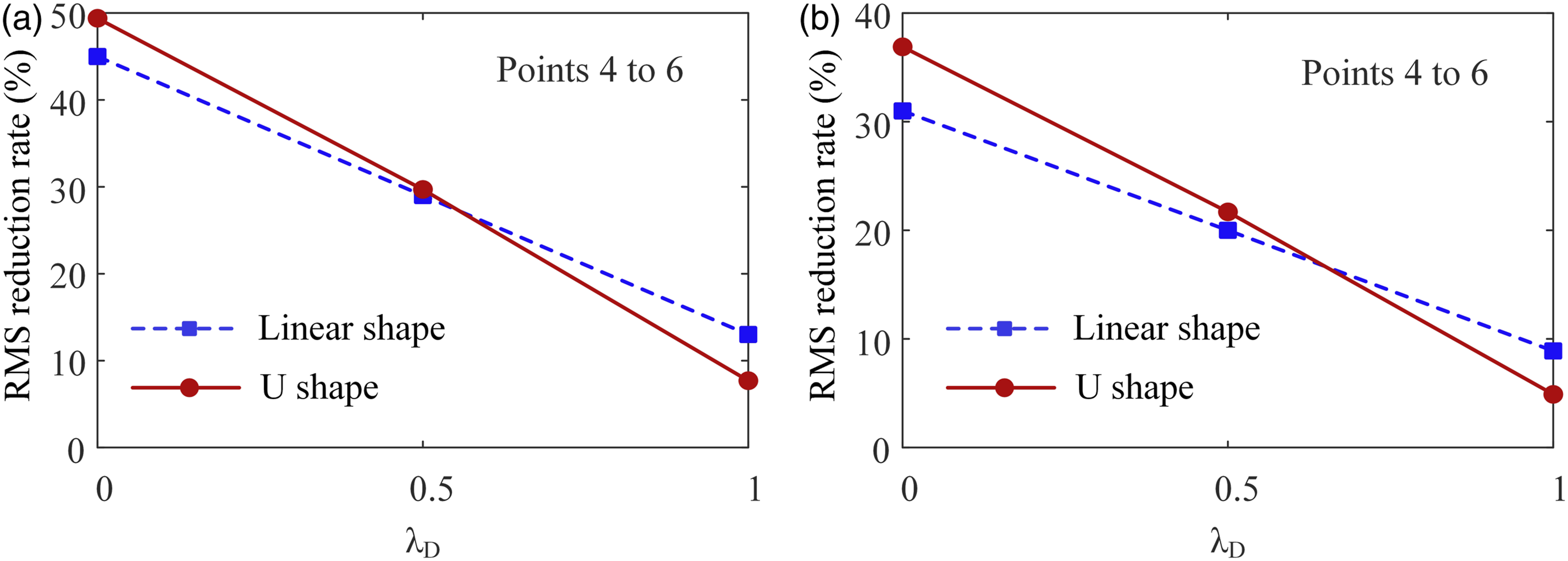
4.2. The dynamic responses of building 2
Figure 13(a) and (b) presents the comparisons of the horizontal dynamic responses with and without the HDIT at point 6 on the major structure of building 2. From this figure, the decrease of peak acceleration and velocity at point 6 are 44.5% and 39.6 %, whereas RMS acceleration and velocity can be reduced to 39.0% and 40.0%. In Figure 13(c) and (d), the horizontal time histories of responses on the top of the attachment structure of building 2 are depicted. It can be observed that the attachment structure suffers from the vibration more than the major structure during a train passage, which indicates that a potential safety hazard under long-term train-induced vibration may occur to the attachment structure. However, this damage can be effectively avoided after using the HDIT as shown in Figure 13, with peak values reducing to 43.1% and 44.0% for the acceleration and velocity, respectively. Horizontal dynamic responses of building 2: (a) acceleration of major structure; (b) velocity of major structure; (c) acceleration of attachment structure; and (d) velocity of attachment structure.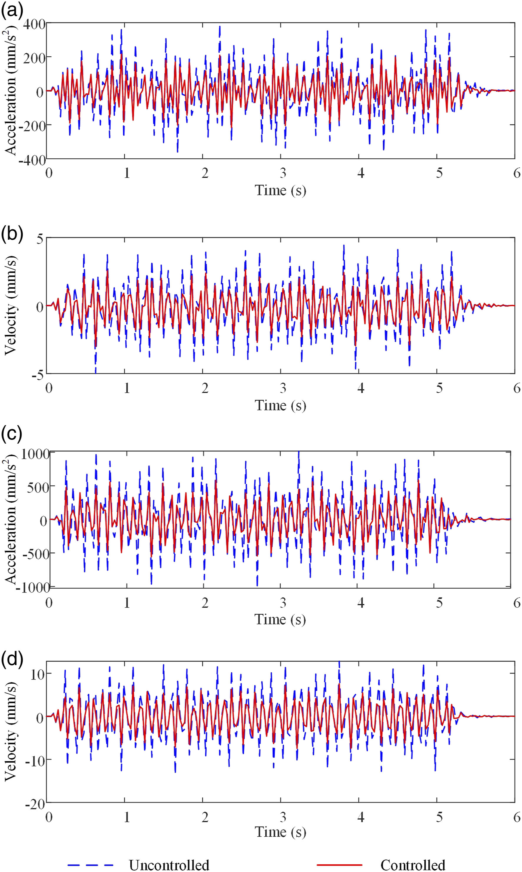
Figure 14 presents the horizontal dynamic responses at different points on building 2, and the corresponding reduction rates at the points on the roof are presented in Table 2. It is observed that for the points on the ground, whether the HDIT is applied or not, all the dynamic responses decrease with the increase of λD. However, for the points on the roof, the dynamic responses remain stable with the variation in λD. This is because the wooden truss has large axial stiffness, which can make the structure keep overall lateral displacement on the top. It can also note that the responses at point 7 are larger than those at other points, which can be explained by the influence of the attachment structure. Therefore, reducing the local responses is equally important for protecting the whole structure. Figure 14 also shows the performance of the HDIT at each point. It can be seen that the horizontal dynamic responses with the HDIT are obviously smaller than those without the HDIT. The respective maximum reduction rates of peak acceleration and peak velocity are 48.4% and 48.7%. Meanwhile, because of the sufficient distance between the HDIT and the building in the east–west direction, few waves that bypass the end of the HDIT can affect the structure. As a result, the HDIT can still be effective in attenuating the responses for the points where λD > 0.5. Effect of high damping isolation trench at each point of building 2: (a) peak acceleration and (b) peak velocity.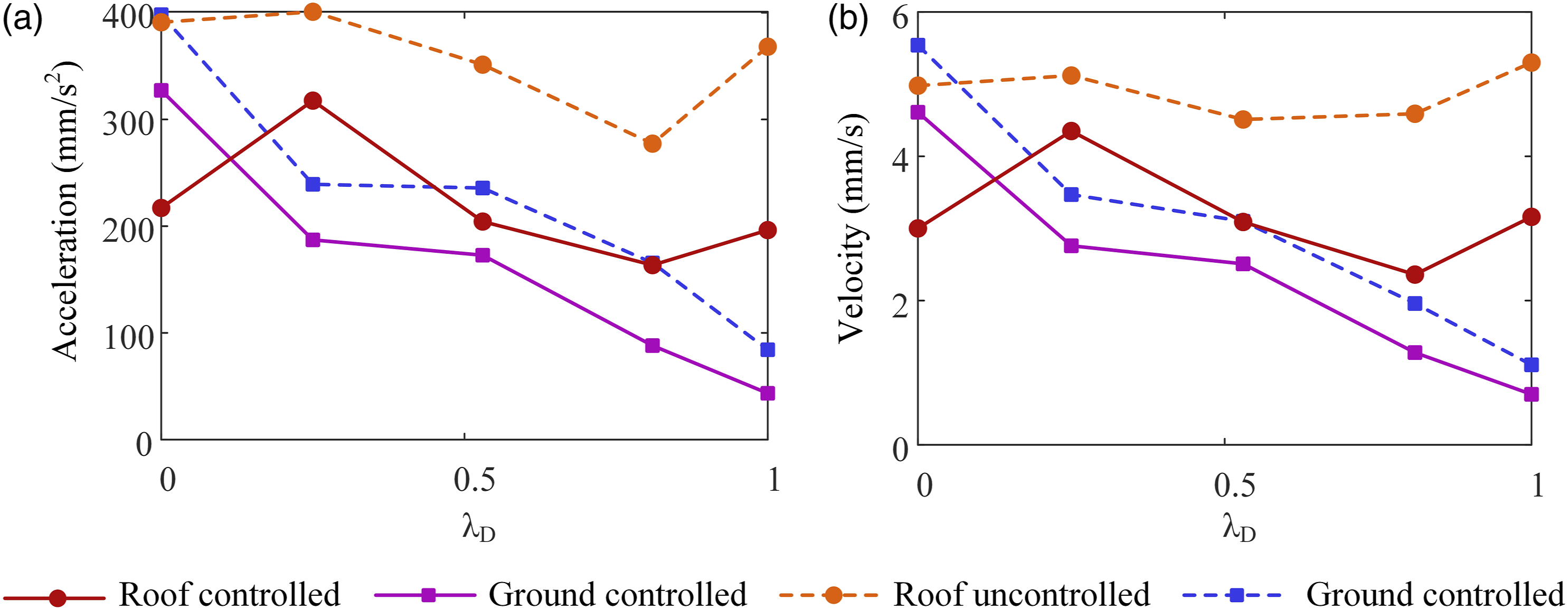
The horizontal dynamic responses on the top of building 2, as shown in Figure 15, are calculated for the HDITs with different plane shapes. Apparently, the isolation performance of the HDIT with L-shaped trench can be remarkably improved, when compared to the case of applying the conventional linear-shaped trench. It can be seen that for the rectangular-shaped building 2, apart from the cross wall, the long longitudinal wall that in the north–south direction is also vulnerable to the vibration. However, despite the linear-shaped trench can provide a wider isolation range for the sufficient length, it can barely work for the longitudinal wall, and the vibration wave still can act on this wall after penetrating the trench. On the contrary, for the L-shaped trench, because of the long segment arranged in the north–south direction, more energy can be dissipated before reaching the building. Therefore, it can be concluded that the L-shaped trench considers the shape characteristics of building more comprehensively so that can perform more effective than the conventional linear-shaped trench in this project. Reduction rates of the root mean square responses on the top of building 2 because of different shapes of the trench: (a) acceleration and (b) velocity.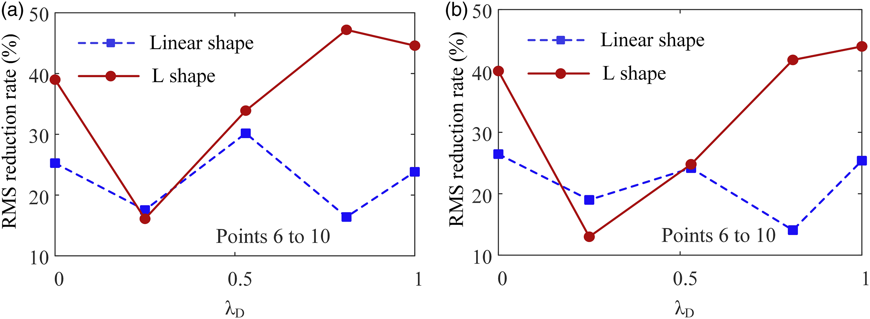
5. Conclusions
In the present study, a novel HDIT with viscoelastic braces is developed to improve the efficiency of conventional isolation trench and guarantee the stability of the surrounding soil after excavation. Two types of HDIT with U shape and L shape are designed to reduce the potential damage of two ancient buildings subjected to train-induced vibration. And their control effects on these buildings are investigated by three-dimensional finite\infinite analysis. The main conclusions can be drawn as follows: The results of dynamic response analysis of building 1 show that the novel HDIT has excellent control effects. Under the given excitation, the maximum reduction rates of peak acceleration and peak velocity in horizontal are 52.5% and 47.0%, respectively. Because of the energy dissipation provided by the HDIT, the vibration whose frequency is close to the structural eigenfrequency can be apparently decreased. Thus, the safety of the structure can be effectively secured. The dynamic response analysis results of building 2 show that the novel HDIT can effectively mitigate the vibration both for the major structure and the attachment structure. Under the given excitation, for the major structure, the reduction rates of peak acceleration and peak velocity in horizontal can be up to 48.4% and 48.7%. Besides, for the attachment structure, the peak values can be reduced to 43.1% and 44.0% for the top acceleration and velocity. Therefore, all parts of the building can be protected against further damage. For the project discussed in this study, the U-shaped and the L-shaped trench can be used to achieve better performance and dissipate more energy instead of the conventional linear-shaped trench because they take the characteristics of the protected structures into account. At the same time, they can also overcome the restriction of site condition so that a wider range of application can be achieved in practical engineering. Nevertheless, the segments of these trenches that parallel to the vibration propagation direction still need to have an appropriate length or keep sufficient distance from the structure. It can prevent wave from bypassing the trench and further affecting the structure.
Footnotes
Declaration of conflicting interests
The author(s) declared no potential conflicts of interest with respect to the research, authorship, and/or publication of this article.
Funding
The author(s) disclosed receipt of the following financial support for the research, authorship, and/or publication of this article: This research is financially supported by the Program of Chang Jiang Scholars of Ministry of Education, National Science Fund for Distinguished Young Scholars with Grant No. 51625803, Ten Thousand Talent Program of Leading Technologists, the Distinguished Professor for Jiangsu Province, and the Jiangsu Province International Cooperation Project with Grant No. BZ2018058. These supports are gratefully acknowledged.