
Abstract
Tuned mass dampers are well-known devices for efficient reduction of structural vibrations; however, they can only control the vibration of a single mode in a narrow frequency range and are not easily retunable. This article presents a semi-active tuned mass damper, consisting of a piezoelectric device connected to an external resistive–inductive electric circuit, which enables multi-modal vibration control, is highly tunable, and introduces high damping. The dynamics of the coupled electromechanical system, which includes the primary and auxiliary masses, the piezoelectric device, and the shunt circuit, are analyzed and the effect of the resistance and inductance is investigated. An experimental prototype using a specialty piezoelectric device is fabricated and tested. The experimental measurements greatly agree with the analytical results, validating the strong electromechanical coupling and the enhanced vibration suppression capabilities of the proposed damper. Moreover, the variation of inductive impedance demonstrates substantial semi-active broadband multi-modal vibration control potential, by introducing an additional highly tunable electromechanical resonant oscillator in the system dynamics, and also by enabling the enhancement of coupling and energy dissipation on targeted modal frequencies.
1. Introduction
Excessive vibrations in mechanical applications are undesirable, as they affect the safety and comfort of the nearby human presence and may lead to material fatigue deterioration or even failure. Tuned mass dampers (TMDs), also known as dynamic vibration absorbers (DVAs), initially proposed by Frahm (1911), have been used as means of vibration reduction for over a century. Traditionally, these devices are attached to the main structure and consist of a spring–damper element and a small auxiliary mass, which is able to oscillate independently and as a consequence absorbs part of the kinetic energy of the system (Elias and Matsagar, 2017). The dynamic characteristics of this absorber are chosen, such that the TMD is tuned to a resonant frequency or dominating excitation frequency, resulting in significant vibration suppression of the main structure via the introduction of a tuned anti-resonance and modest dissipation. Den Hartog (1956) explored the tuning rules of the TMD, developing and establishing the fixed-point theory; however, many optimization approaches have also been investigated and tested (Krenk, 2005; Zilletti et al., 2012). Moreover, to compensate for the uncertainty of system variables and the fact that maximum vibration reduction is achieved only when the TMD is lightly damped, Marano et al. (2007) proposed a robust optimum design criterion for the case of random vibrations. Yet, TMDs suffer from severe limitations because they can only control the vibration of a single mode in a narrow frequency range and are not easily retunable. Multiple mass dampers have been proposed and thoroughly investigated (Igusa and Xu, 1994; Kareem and Kline, 1995; Zuo, 2009), providing damping effectiveness to multiple resonant or excitation frequencies, but this solution may add substantial weight and limited tuning capability. Although the integration of a TMD in a structure typically introduces an anti-resonance on a single frequency of interest, it also generates two new frequency peaks, one slightly lower and another slightly higher than the initial resonance, which can be of similarly high amplitude, especially when the TMD is lightly damped. Furthermore, these mechanical devices are not easy to retune, in the event of an alternation in the dynamic characteristics of the system (e.g., mass diminution). To deal with the aforementioned limitations, some developments in adaptive TMDs have been presented (Brennan, 2006); however, substantial improvements still have to be made to enable multi-modal control, adaptivity, high energy dissipation, and reduced weight. These are important requirements for the vibration control in aerospace structures.
Alternative vibration reduction can be achieved if the kinetic or strain energy of the structure is transformed into electrical energy and then dissipated by electric means. This energy conversion can be realized by integrating an electromechanically coupled transducer (piezoelectric (Forward, 1979) or electromagnetic (Fleming and Reza Moheimani, 2003)) into the vibrating structure, shunted to an external circuit with a given resistive–inductive–capacitive (RLC) impedance. In the electric circuit, the resistive, inductive, and capacitive components are the electrical analogs of damping, mass, and reciprocal of stiffness of a purely mechanical system, respectively. Piezoelectric transducers directly convert strain energy to electrical through the direct piezoelectric effect. Electromagnetic transducers, on the other hand, are limited to metallic or magnetic applications and demand the presence of an external coil to achieve the desirable electromechanical energy conversion.
Shunted piezoelectric patches and films attached to the surface of a vibrating structure have gathered extreme scientific attention since the original pioneering works of Forward (1979) and Hagood and Von Flotow (1991). This is because shunt dampers offer great tuning and retuning potential, by simply changing the levels of impedance of the external circuit. For the prediction of resistively shunted piezoceramic damping, a modal strain approach was proposed (Davis and Lesieutre, 1995), whereas the mechanics for the analysis of damping in composite plates with multiple resistively shunted piezoelectric layers were developed (Saravanos, 1999) and further extended to also encompass the damping contribution of viscoelastic composite plies (Plagiannakos and Saravanos, 2003). Moreover, the adaptive and self-tuning capabilities of the shunted piezoelectric dampers have been investigated (Hollkamp and Starchville, 1994; Niederberger et al., 2004; Reza Moheimani, 2003). To achieve multiple mode vibration suppression, using only one piezoelectric transducer, and a combination of shunt circuits, various methods have been developed and tested (Hollkamp, 1994; Wu, 1998; Behrens et al., 2003a, 2003b). Synthetic impedance circuits were proposed (Fleming et al., 2000; 2002) to overcome implementation limitations that arise when a low-frequency mode must be suppressed, a task that requires high inductance levels and thus bulky inductors. Conversely, tuning the shunt damper to a higher vibration mode through capacitance requires cancelation of the transducer capacitive impedance; for this reason, negative synthetic capacitance circuits were reported and implemented (Park and Baz, 2005; Neubauer et al., 2006; Neubauer and Wallaschek, 2009). The effect of negative capacitance, inductance, and resistance in the shunt circuit was also investigated to actively control flexural wave band gaps in beam-type acoustic metamaterials, using the piezoelectric shunted technique (Zhou et al., 2019). Finally, synchronized switching techniques were used to the shunt circuit for improved multi-modal damping capabilities (Clark, 2000; Richard et al., 1999). For a more exhaustive review on the shunted piezoelectric damping, the interested researcher can refer to Gripp and Rade (2018), Reza Moheimani (2003).
A simultaneous usage of a classical TMD and an electrically shunted piezoelectric transducer could take advantage of the great vibration suppression capability of the former, and the high dissipation and tuning capabilities of the shunt circuit. After an inertial piezoceramic actuator was introduced Davis et al. (1995), Davis et al. (1997) investigated how the different resistive and capacitive levels of this damper can alter the natural frequency and damping of the system, and subsequently advanced their work by incorporating an active tuning controller (Davis and Lesieutre, 2000). A vibration absorber with tuned resistive and negative capacitance shunt circuits was reported by Heuss et al. (2016). Furthermore, Lallart et al. (2013) demonstrated an electromechanical TMD featuring piezoelectric elements with nonlinear synchronized switch damping on inductor (SSDI), using a 2-degree-of-freedom (2-DOF) model, validated by experimental results. Moreover, the simultaneous energy harvesting, vibration reduction capabilities, and parameter optimization of an electromechanical damper were analytically investigated on a 2-DOF model (Ali and Adhikari, 2013). The H2-optimization criterion was used by Zhao et al. (2015, 2016) for tuning the RC and RL shunt circuits of a vibration absorber, and then applied on their method for the suppression of structural vibrations in rotating machinery (2016). More recently, Høgsberg (2019) reported a theoretical investigation of the root loci of a 3-DOF system, consisting of a structural mass, the absorber mass, and an RL shunted ideal piezoelectric element, and used the principal of equal damping (Høgsberg and Krenk, 2012; Krenk, 2005) to determine the optimal parameters of the system. Although the latter was an important theoretical investigation, it seems that a comprehensive analysis of the damper performance, validated by experimental results, is further required. Finally, an investigation and experimental demonstration of the performance of an electromagnetic shunt damper, combined with a conventional TMD, has been reported (Auleley et al., 2020).
The present work presents the development of a semi-active TMD (SATMD), which uses a realistic piezoelectric device between the structural and the auxiliary oscillator mass, that provides the mechanical stiffness, the electromechanical energy conversion, and the coupling with a shunt RL circuit. The scientific contributions of the current work lie in the following main axes: the in-depth investigation of the complex electromechanical performance of the SATMD system; the analysis of the involved multi-modal vibration control, tuning mechanisms, and capabilities; the development of a TMD prototype encompassing a realistic piezoelectric device, that combines high piezoelectric coupling and low inherent mechanical stiffness, such that low-frequency vibrational modes can be suppressed without the employment of a bulky mass; and finally, an extensive experimental study on a lab-prototype, that validates the analytical results and physically demonstrates the great vibration reduction and tuning capabilities.
The rest of the article is organized as follows. In Sections 2 and 3, the theoretical background of the combined damper and the description of the experimental setup of a 3-DOF prototype are presented, respectively. Analytical and experimental results are shown in Section 4, that quantify the electromechanical performance and vibration control capabilities of the SATMD for various combinations of resistive and inductive impedance, along with a proposed retuning process. An in-depth investigation and interpretation of the complex intermingling of the electromechanical poles are also presented. In the final section of this article, concluding remarks and possibilities for future research are outlined.
2. Theoretical background
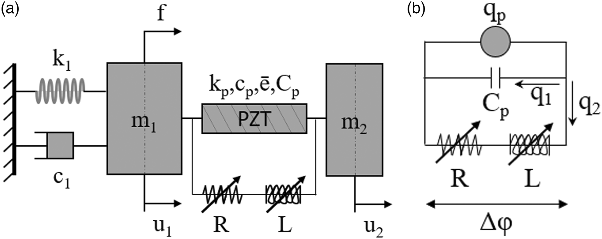
The equations of motion of the proposed electromechanical TMD are presented in this section, comprised of a simplified 1-DOF lumped mass model of the host structure and an auxiliary mass attached to it. In a conventional mechanical TMD, the two masses are connected with a spring–damper element (Figure 1); however, in the electromechanical TMD, the two masses are connected with a piezoelectric transducer, which is further connected to an external circuit (Figure 2). Baseline structure with purely mechanical tuned mass damper. Electromechanical TMD. (a) Shunted piezoelectric TMD; (b) electric circuit. Note: TMD: tuned mass damper.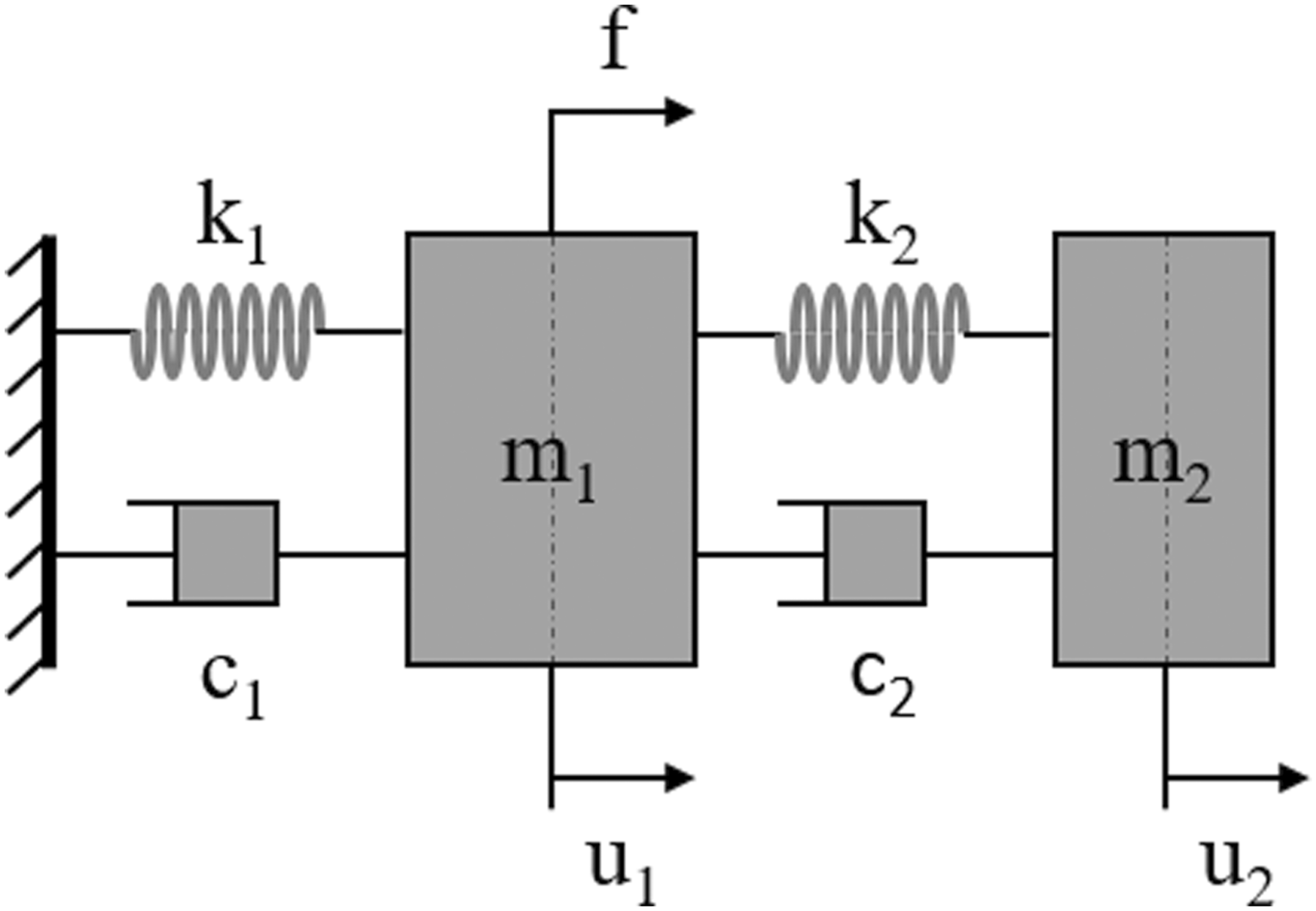
2.1. Conventional TMD
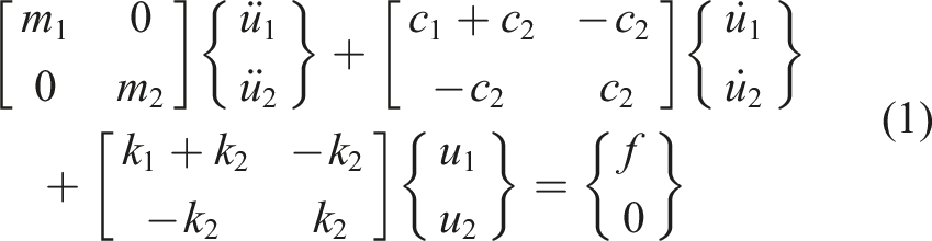
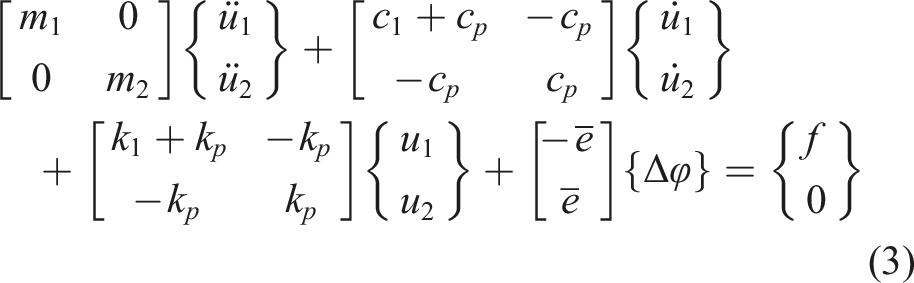
The dynamic equilibrium equations of the conventional purely mechanical TMD, illustrated in Figure 1, have the form
2.2. Electromechanical TMD with piezoelectric transducer
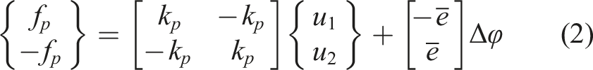
In the shunted piezoelectric TMD, the connecting spring–damper element of the conventional TMD is substituted with a suitable linear piezoelectric transducer, as shown in Figure 2(a), which provides mechanical stiffness, electromechanical energy conversion, and coupling between the motion of the mechanical and electrical systems. The internal force f
p
applied by the piezoelectric device is related to its deformation, and also the applied electric potential difference Δφ at its edges
2.2.1. Open circuit piezoelectric TMD
Electric charge q
p
is created in the piezoelectric device, which is stored in its electrical capacitance C
p
, when it is not shunted by an external circuit. Hence, an additional equation of motion is introduced, which describes the equilibrium of electric charge in the piezoelectric transducer (Figure 2(b))

Combining equations (3) and (4), the equations of motion for the open electromechanical TMD can be presented as
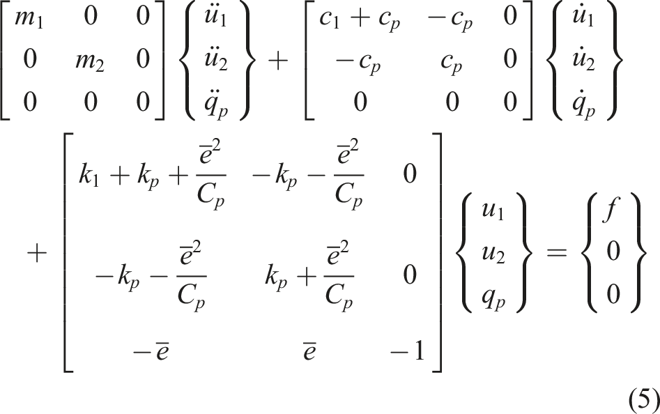
Comparing this equation to the one of the purely mechanical TMD, it is easily understood that the internal energy of the system is now stored as strain energy in the springs, but also as electrical energy in the piezoelectric element, resulting in a stiffness variation of the system by the ē2/C p term. This implies that the substitution of the connecting spring–damper element with a piezoelectric material is itself capable of altering the system elastic characteristics, depending on the piezoelectric coupling coefficient ē2/C p .
2.2.2. Shunt circuit
The real tuning capabilities emanate when a shunt circuit, as presented in Figure 2(a), is used including variable resistive and inductive impedances. Under these circumstances, the electric charge q
p
generated from the relative movement of the structure and the absorber mass is stored in the piezoelectric capacitance (q1) and also flows through the shunt circuit (q2) in the form of electric current, as shown in Figure 2(b)

Moreover, the potential difference is now equal to
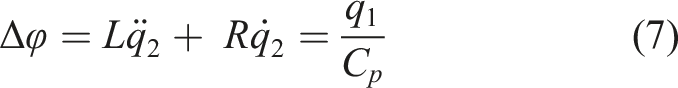
Combining equations (6) and (7), the final expression of the charge equilibrium in the shunt circuit becomes

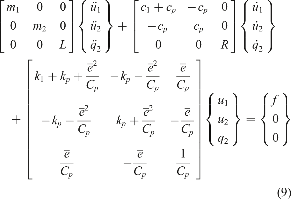
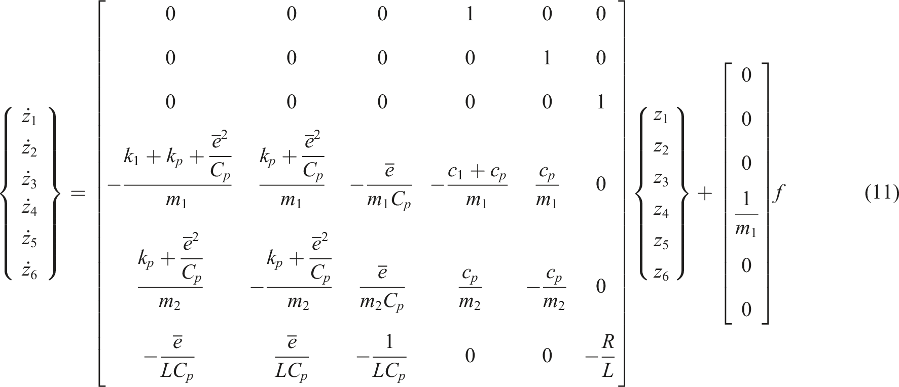
Finally, combining equation (8) with (3), the dynamic equation of shunted piezoelectric TMD can be presented as

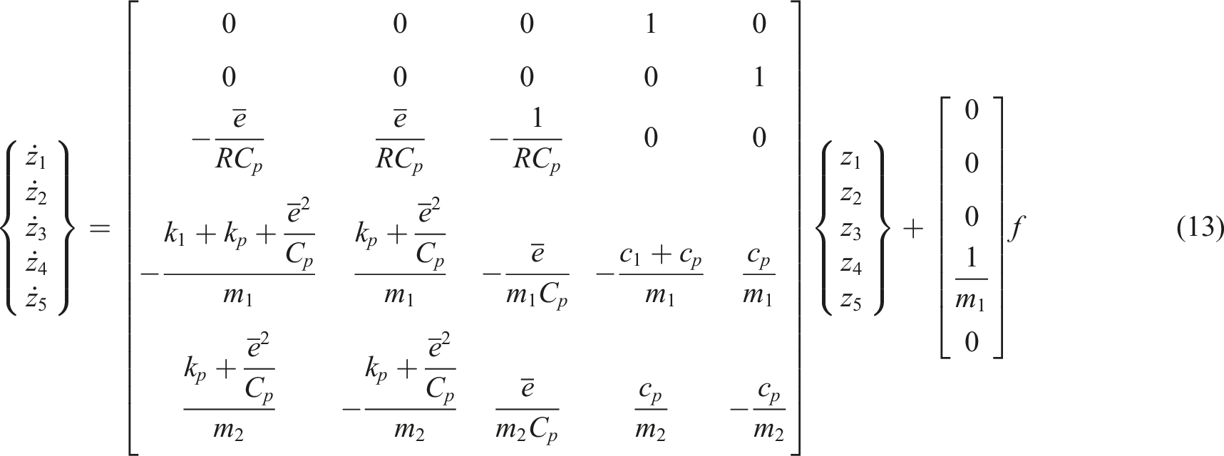
In the special case of only resistive shunt impedance (L = 0), the state-space system is reduced to

3. Experimental setup and model validation
The experimental validation of the electromechanical TMD concept and its vibration reduction capabilities are evaluated on a simplified 1-DOF host structure (Figure 3). The details of the experimental setup, the resistive and inductive components used in the external circuit, the crucial selection of the real-applications-employable piezoelectric transducer, and the procedure of the proposed 3-DOF shunted piezoelectric TMD model validation are described in the present section. Experimental setup.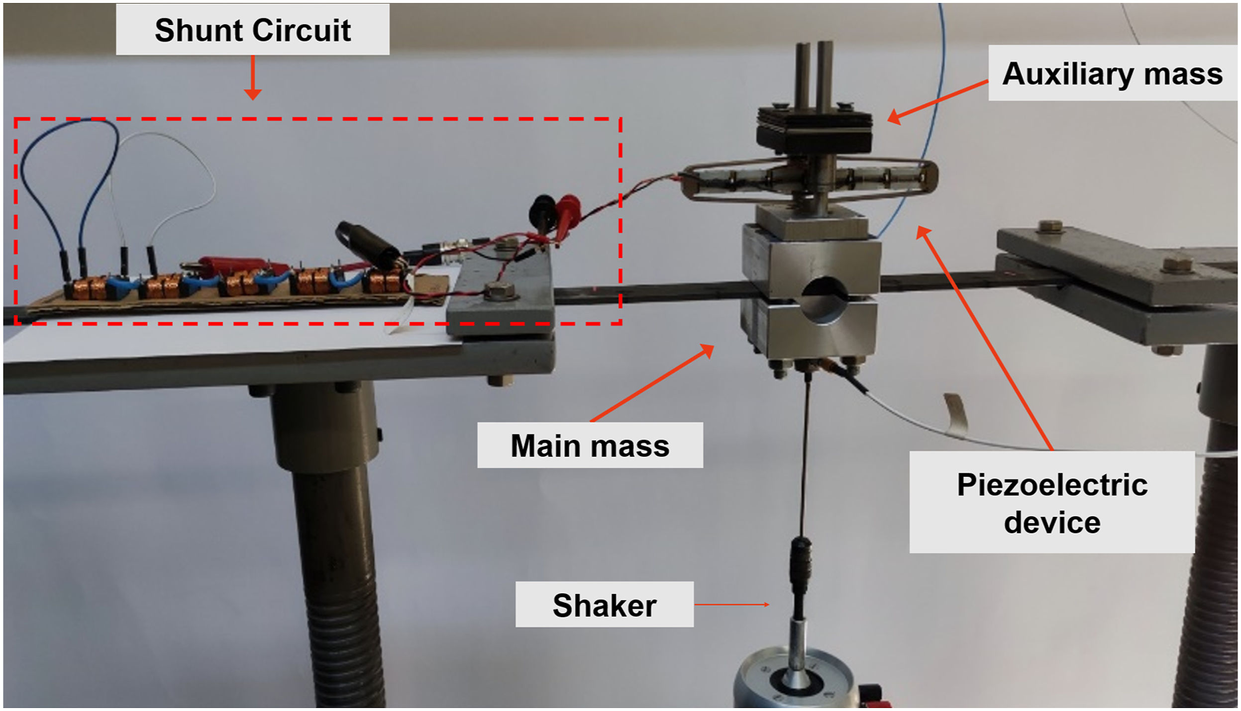
3.1. Experimental setup
The experimental setup is illustrated in Figure 3. The 1-DOF host structure consists of a mass firmly attached at the center of a carbon fiber–reinforced polymer (CFRP) double cantilever beam, permitting only a vertical movement. The force excitation is introduced directly through the main mass via a shaker, which applies a white noise excitation to the structure, to obtain its acceleration frequency response functions (FRFs), using a triaxial accelerometer. For the electromechanically shunted TMD, a diamond-shaped piezoelectric transducer (Zhou and Henson, 2007) is attached between the main and the absorber mass, whose terminals are shunted to a circuit with electrical impedance. The resistive impedance is controlled by an easily tunable potentiometer, whereas variable inductive loads are introduced by reconfiguring two sets of coils, each having a predefined inductance of 32 mH and 50 mH, respectively. It is pointed out that the coils are not ideal, meaning that they do not introduce pure inductance to the circuit, but they also add a small amount of resistance. To mitigate this imperfection, the resistance of each coil combination was measured using a RLC meter, before included in the analytical model of the shunted piezoelectric TMD. For the complete integration of the used setup, signal conditioners and a power amplifier for the shaker are also used.
3.2. Piezoelectric transducer selection and model calibration
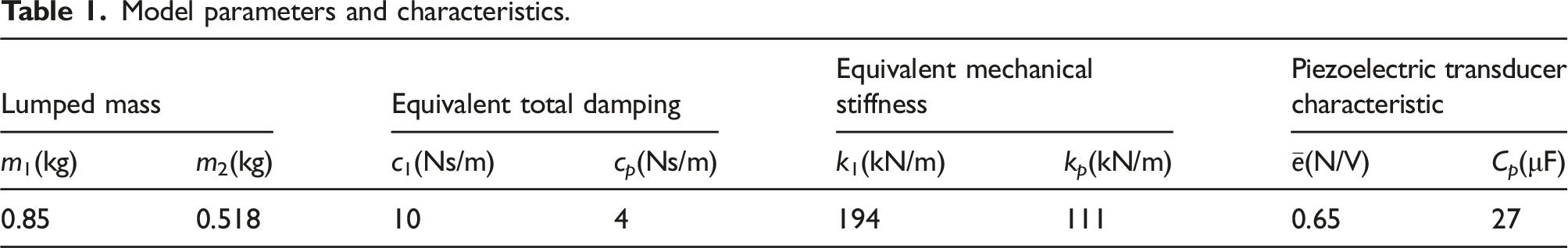
An ideal piezoelectric transducer for the TMD configuration should exhibit: (1) high equivalent piezoelectric coefficient, such that a significant part of the kinetic energy can be transformed into electrical energy and consequently directed in the shunting circuit and (2) low mechanical stiffness, such that mechanical tuning at low frequencies can be achieved by a low auxiliary mass. To simultaneously fulfill the low stiffness and high coupling requirements, the diamond-shaped piezoelectric transducer APA-1500L (Cedrat Technologies, version 5.1, 2019) is used in the proposed electromechanical TMD mechanism, as shown in Figure 3. This device consists of two piezoelectric stacks and a stroke amplifying mechanism, which reduces the equivalent mechanical stiffness. This device was selected among other similar transducers, as it provides the lowest possible mechanical stiffness, whereas its coupling coefficient remains sufficiently high. The concerns of brittleness and failure are addressed with the adopted actuator mechanism, which encapsulates the piezoelectric stack in the frame and under pre-compression. The static loading of the actuator by the auxiliary mass further enhances the compression of the piezoelectric stack. Finally, dielectric and piezoelectric losses of piezoelectric transducers may not always be negligible (González et al., 2016); hence, in this work, the mechanical losses of the device and the transducer are added by the equivalent c p damping term.
Model parameters and characteristics.
4. Results and interpretation of shunted piezoelectric TMD performance
This section covers the demonstration of the results of the aforementioned setup, and the interpretation of the effect of the various impedance levels to the system. The comparison of experimental and simulation results is introduced through acceleration FRFs, whereas for the complete electromechanical coupling and full vibration reduction potential understanding, root loci and amplitude frequency impedance simulations are illustrated. The impedance effects are separated into purely resistive, inductive under constant resistance, and inductive under varying resistance, routing out which impedance best serves for broadband or multi-modal control. Finally, a case study of mass diminution of the baseline structure is taken into consideration, to demonstrate the straightforward retuning capabilities of the proposed SATMD.
4.1. Analytical model
The simulation is carried out in a MATLAB research code by transforming equation (9) into frequency domain. The solution yields the steady-state displacement of the structure and the auxiliary mass, and the steady-state shunt circuit charge for each frequency increment. For comparison to the experimental results, the structural acceleration for each frequency increment is computed, and its magnitude is expressed in decibels (dB). The resistance effect is calculated for zero inductance, whereas for the inductance effect, the inductance value of each coil combination and the respective measured resistance are used.
4.2. Resistance effect
The effect of a purely resistive shunting circuit is investigated first. Figures 4(a) and (b) illustrate the experimental and simulation results, respectively, for resistance values that extend between 3 Ω and 500 Ω. The response of the sole structure without the attachment of the SATMD is marked as “Baseline” and denoted by the blue curve. A strong resonance is observed at approximately 73 Hz, which is the eigenfrequency of this baseline structure. The attachment of the mechanical TMD (short circuit) highly attenuates the amplitude of vibration in the band vicinity of the baseline eigenfrequency, proving the great vibration suppression capabilities of the passive damper for a single mode. However, the TMD also introduces two new frequency peaks, away from the baseline resonance, corresponding to structural mode I for the lowest eigenfrequency (approximately 53 Hz) and structural mode II for the higher one (approximately 110 Hz). The shunt resistance and inductance of the SATMD will be used to attenuate the amplitude of these two new frequency peaks to achieve broadband vibration control. Excellent agreement is observed between the simulation and experimental results depicted in Figures 4(a) and (b). As expected, there is considerable effect of the resistive impedance on the FRF of the system, mostly as added damping, as the frequency response acceleration of the structure varies between the two extreme situations: open circuit (infinite resistance) and short circuit. Starting the interpretation from the short circuit (zero resistance) configuration, the charge generated in the piezoelectric stack is almost entirely transferred to the shunt system, leaving the piezoelectric capacitor uncharged; thus, there is no dissipation and damping. At the same time, the strain energy in the piezoelectric device reaches its highest value that minimizes its phenomenal stiffness, as manifested by the lower values in the corresponding frequency peaks. As the shunt resistance increases, some of the electrical energy flowing through the shunt circuit is dissipated into heat, and some charge is stored at the capacitor, which leads to reduced elastic energy in the piezoelectric device. The first effect adds damping to the system, whereas the second one increases the phenomenal stiffness of the device. At certain levels of resistance, the energy dissipation is maximized. For higher resistance, a low-pass filter is created in the shunt circuit, which reduces the flow of energy and dissipation through the resistor. The maximum strain energy in the piezoelectric device is also reduced, leading to phenomenal stiffening, which dominates the system response, resulting in higher amplitudes and frequencies, as the infinite resistance (open circuit situation) is reached. Resistance effect on structure: (a) experimental results and (b) simulation results.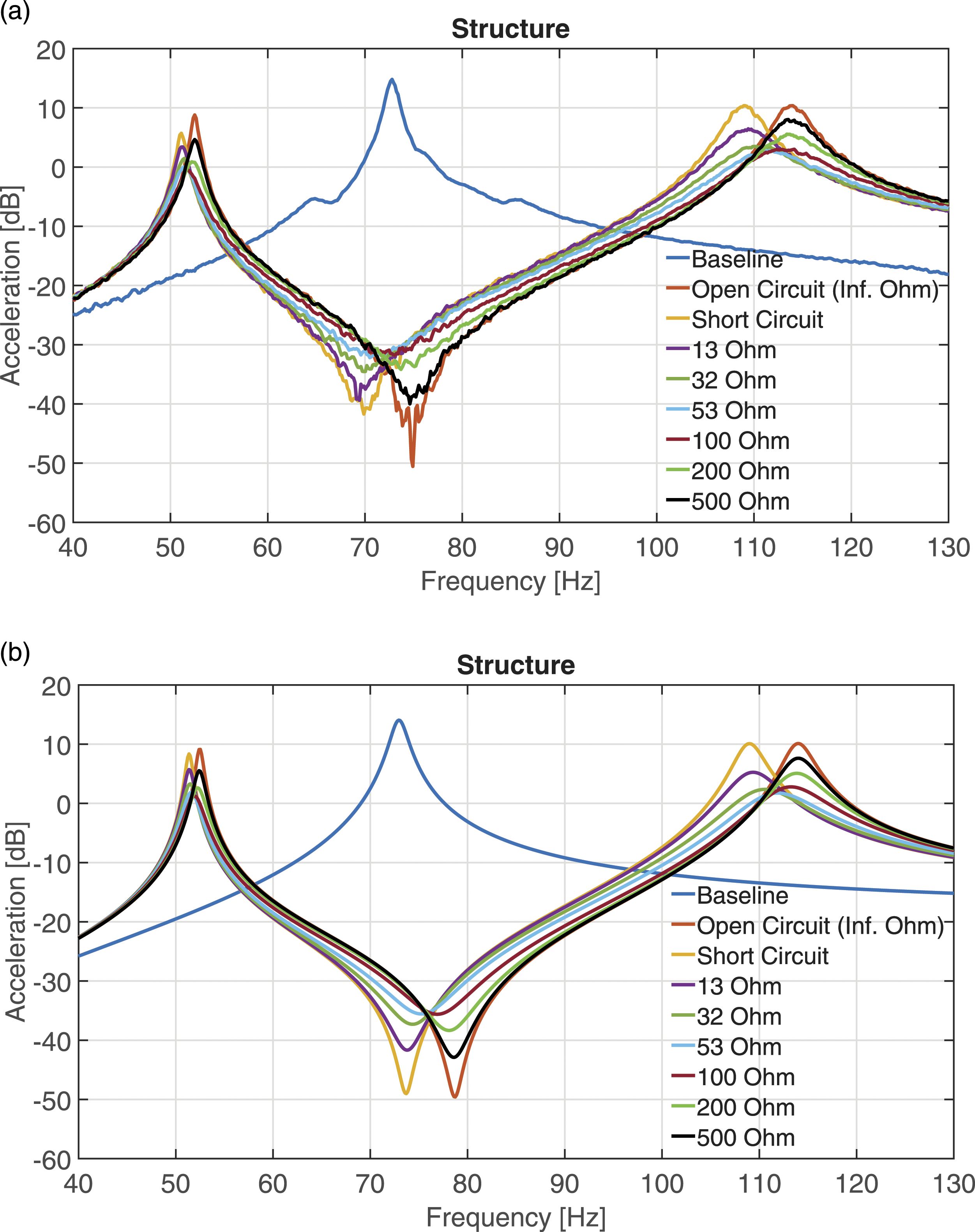

Ultimate experimentally obtained reductions in modal peaks.
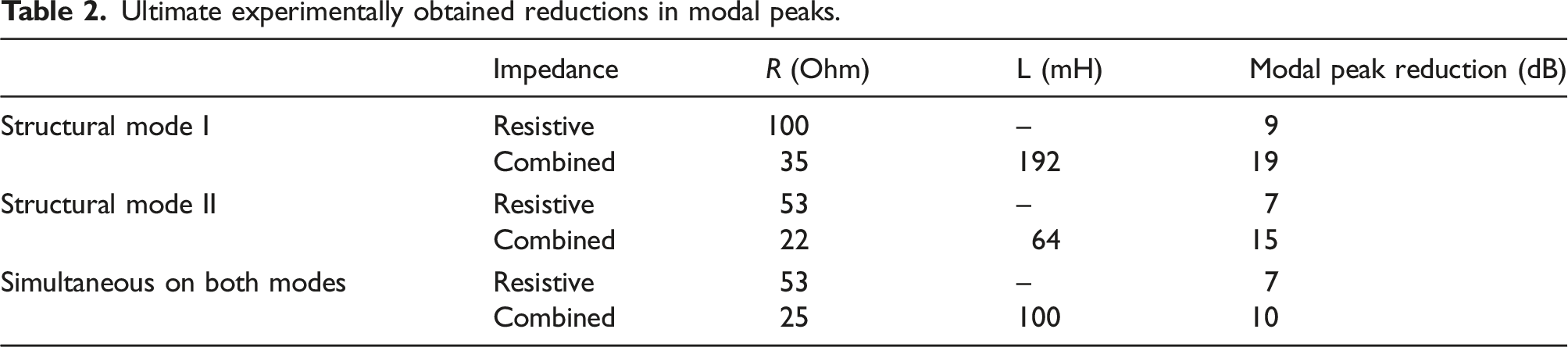
Root Loci for increasing resistance. Symbols “+” and “*” indicate the pole locations of maximum modal damping for structural mode I and II, respectively.
This point corresponds to R = 52 Ω, and the respective pole locations in Figure 5 are shown with symbol “*” in the root loci. Similarly, when resistance value reaches 98 Ω, the respective cutoff frequency of the electric circuit reaches the modal frequency of mode I, and the respective modal damping is maximized, as illustrated with symbol “+.” For resistance between the previous values, simultaneous vibration suppression is obtained for both modes.
4.3. Inductance effect
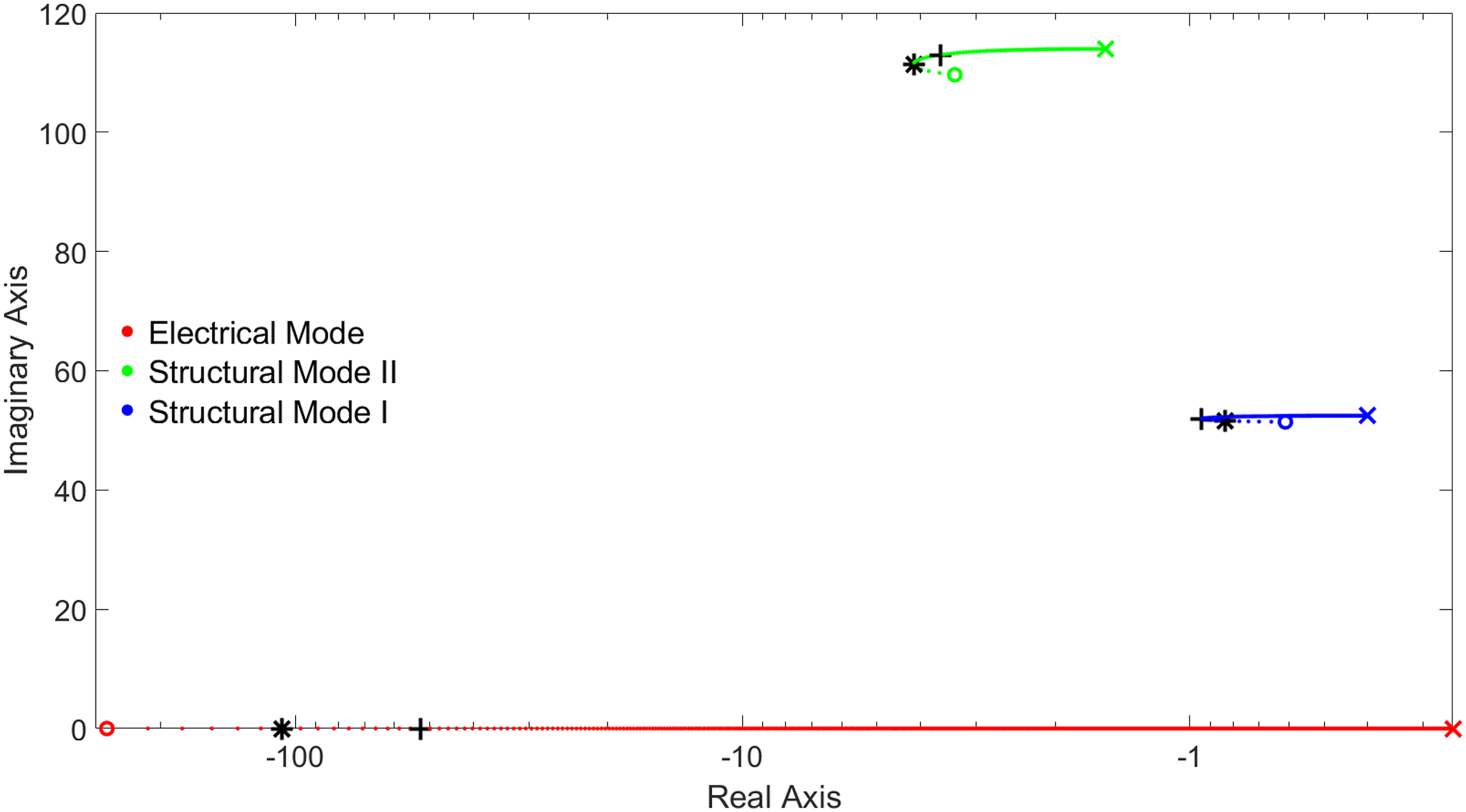
The effect of inductive impedance increase under negligible resistance (R = 1 Ω) is illustrated in Figures 6(a), (b), and (c), where the amplitude of the main and auxiliary mass accelerations and the electric charge q2 are presented in the frequency domain. The 3D plots can be intuitively understood as the frequency response functions of each DOF that correspond to various impedance values. As seen in equation (9), the inductive impedance adds a third complex conjugate pair of poles into the system, corresponding to a mostly electrical mode, which is manifested as a third modal peak in Figure 6, and has a great effect on the dynamics of the electromechanical TMD. As seen in Figure 6 for very low impedance values, the electric modal frequency is separated from the structural modal frequencies, hence there is very little coupling and interaction between the mechanical and the electric circuit dynamics. As inductance rises, the third electrical mode descends to lower frequency band, and as it approaches the higher mechanical mode (Figure 6(c)), its amplitude is increasing rapidly, as shown for the cases of 35 mH and 50 mH in Figure 6(d). The respective modal peak appears in the response of the auxiliary and main mass (Figures 6(a) and (b)). The latter indicates progressively increasing strong electromechanical coupling in the whole system, and large conversion of kinetic to electrical energy. As the inductive impedance approaches 100 mH, the two frequencies approach each other, and sudden switching in the modes takes place. This sudden mode switching between electrical and mechanical modes is defined as bifurcation in the current study and will be further explained later in the current section. After this first bifurcation point, further inductance increase leads to the separation of the two peaks; the structural peak vastly raises its amplitude, whereas the electrical peak reduces it. These denote that the electrical pole has passed through the second mode and has progressively decoupled from it. As the inductance increases further, the electrical mode tends to reach the first structural mode. Similarly to the previous case, as the inductance increases from 100 mH to 300 mH, the electrical and first structural modes become highly coupled, whereas further inductance increase leads again to a second bifurcation, associated with rapid mode switching and opposite amplitude movement in the 3D plots, indicating the new electrical pole pass-through and subsequent decoupling. It is important to stress out the high coupling between the electrical and mechanical modes near the two bifurcation points. The high electromechanical coupling has two important mechanisms for controlling the main mass vibration. First, it effectively introduces a second resonant oscillator in the system, also introducing a second anti-resonance in the structural mass, which is highly tunable via inductance. Most importantly, the impedance value increases electromechanical coupling near the bifurcation points, resulting in large conversion of kinetic to electrical energy and vice versa, during the system vibration. The latter opens the way for high energy dissipation, as outlined in the next subsection. Inductance effect on frequency response functions. (a) Main mass acceleration; (b) auxiliary mass acceleration; (c) shunt circuit charge; and (d) shunt circuit charge cases: short circuit, 35 mH and 50 mH.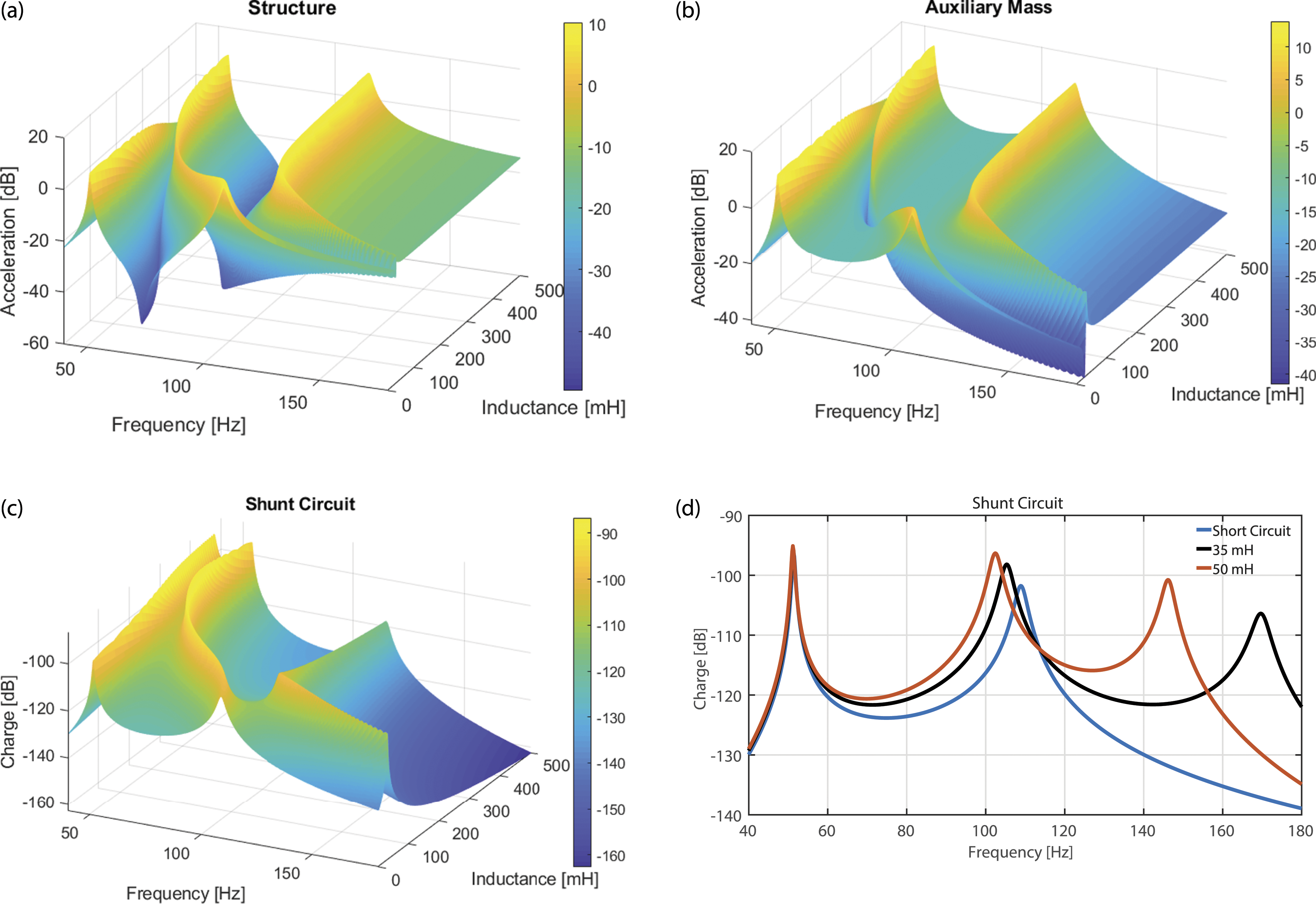
For better illustration of the bifurcations that occur under varying inductance values and negligible resistance (R = 1 Ω), the electrical components of the eigenvectors, and the pole movement, as derived by the A
L
system matrix of the state space, are shown in Figures 7(a) and (b), respectively. In Figure 7(a), the electrical component of each eigenvector (Φel1, Φel2, and Φel3) alters as inductance increases, illustrated by the three different curves: solid curve, dashed–dotted curve, and dashed curve, respectively. For very small inductance values, Φel1, Φel2, and Φel3 correspond to electrical mode, structural mode II, and structural mode I, respectively; however, inductance increase leads to the diversification of the electrical components, and thus bifurcations, because for each inductance increment, the highest electrical component always corresponds to the electrical mode. The electrical component of the electrical mode is denoted with red color, the electrical component of structural mode II with green, and the electrical component of structural mode I with blue. In Figure 7(b), for the first and second structural mode, and the electrical mode, only the positive conjugate poles are illustrated (in red, blue, and green color, respectively). Symbol “o” represents the poles at the starting short circuit position (L→0), symbol “x” represents the poles in the final position (L = 590 mH), and the directions of the arrows indicate the pole movement under a steady inductance increment. The system roots move on 3 separate loci (1, 2, and 3); however, the structural and electrical poles bifurcate with inductance increase. For low, progressively increasing inductance values, the electrical mode is moving on Locus 1, the higher structural mode on Locus 2, and the lower structural mode on Locus 3. The two bifurcation points (symbols “*” and “+“) with inductance increase and R = 1 Ω. (a) Electrical components of the eigenvectors and (b) root loci.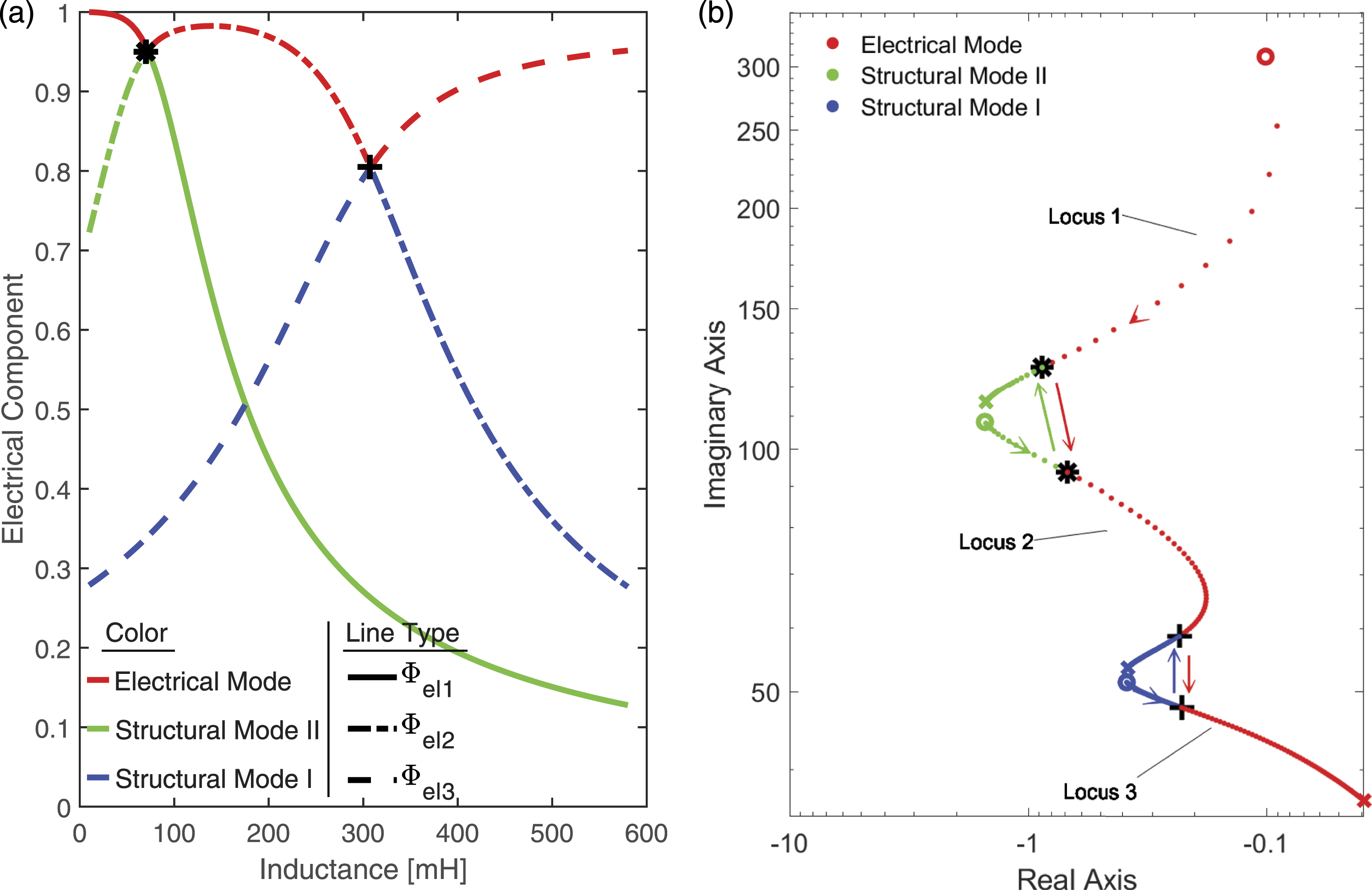
The first bifurcation occurs for L = 70 mH, denoted with symbol “*” in both Figures 7(a) and (b). At this point, the electrical components Φel1 and Φel2 are equal, whereas for higher inductive impedance, Φel2 attains the highest value between the electrical components, and thus corresponds to the electrical mode. For L = 70 mH, the electrical pole and the structural pole II have moved to the “*” position of Locus 1 and Locus 2, respectively. The root of the structural mode I for L = 70 mH is not marked with “*” for visualization reasons because this pole has hardly altered its root. For higher inductance values, a pole jump is associated with this bifurcation, and the electrical pole has moved to Locus 2, whereas the structural mode II has moved to the green roots of Locus 1. Similarly, as inductance continues to rise, the second bifurcation point, shown with the symbol “+,” occurs for L = 305 mH. For this inductance value, Φel2 and Φel3 are equal, whereas for higher inductance, Φel3 attains the highest value and corresponds to the electrical mode. In Figure 7(b), the electrical pole and the structural pole I have moved to the “+” positions of Loci 2 and 3, respectively, whereas for higher inductance, a second pole jump is observed, and the electrical pole continues in Locus 3, whereas the structural pole in the blue roots of Locus 2. Again, the “+” symbol is not shown for the mode that does not participate in the bifurcation (structural mode II), for visualization reasons. Even higher inductance values move the electrical pole to lower frequency band (lower values of the imaginary axis), whereas the poles of structural modes I and II approach their open circuit positions because only a very small amount of electric current is able to flow through the shunt circuit. In summary, the inductance variation leads to the movement of the electrical mode on the red roots, whereas structural mode I and II move on the blue and green roots, respectively.
The electrical component of the eigenvectors and the pole movement of the electromechanical system for increasing inductance values are also presented for the case of considerable resistive impedance (R = 20 Ω) in Figures 8(a) and (b). The increase of resistance slightly affects the system eigenvectors, and the bifurcations occur under the similar circumstances as in the case of negligible resistance. However, all electrical roots, and the majority of the structural roots in Figure 8(b), exhibit much higher values of their real part, compared with the case of R = 1 Ω, indicating greater energy conversion and dissipation, and also a highly damped electrical mode. The two bifurcation points (symbols “*” and “+”) with inductance increase and R = 20 Ω. (a) Electrical components of the eigenvectors and (b) root loci.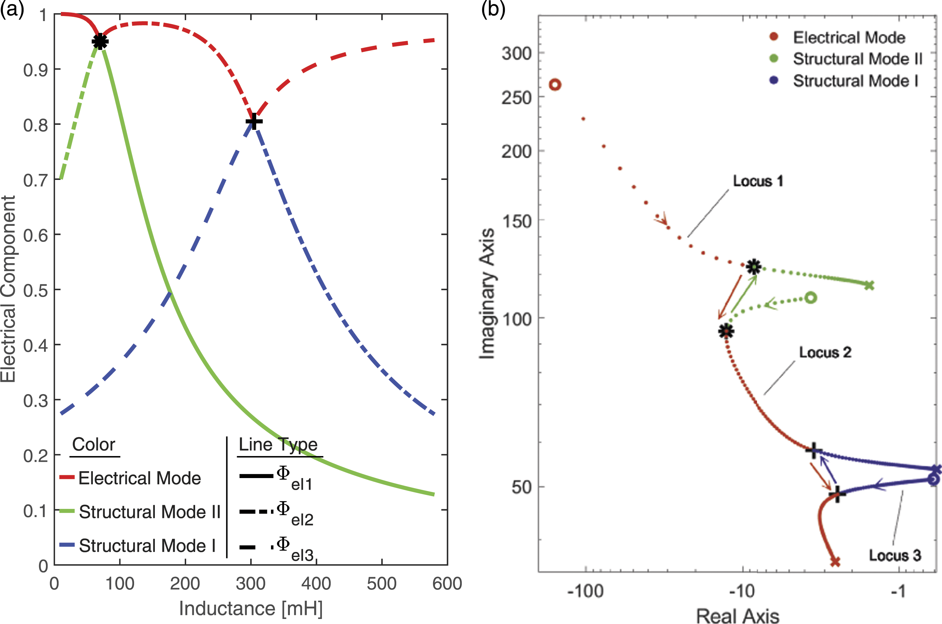
4.4. Combined inductance and resistance effect
The investigation of the combined inductance and resistance effect on the measured and simulation dynamic response of the electromechanical TMD is demonstrated in Figures 9(a) and (b), respectively. A most excellent agreement between the experimental and simulation results is depicted, with minor differences near the first structural resonance for relatively high inductance values, which are most likely attributed to possible imperfections in the connections of multiple coils in series, and as a result in the increased uncertainty in the inductance and resistance levels. Combined resistance–inductance effect on structure: (a) experimental results and (b) simulation results.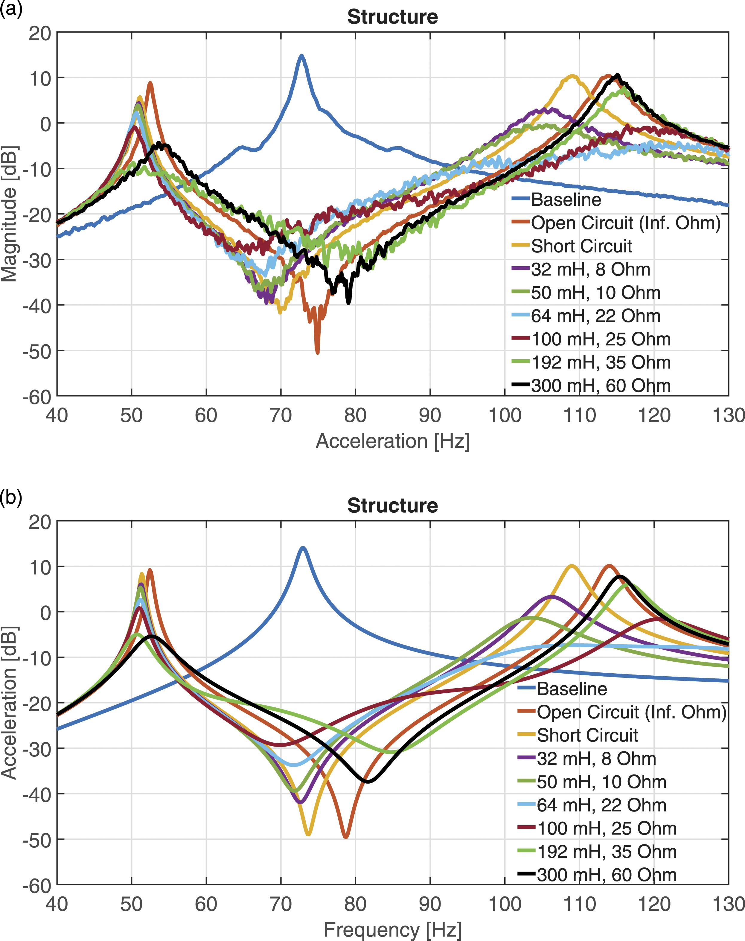
As explained in the previous subsection, the addition of resistance in the shunt circuit was expected to allow the dissipation of the high electrical energy which is available because of the high electromechanical coupling observed in the system, when the electrical pole moved near the structural modes. This is indeed demonstrated in Figure 9. Comparing the amplitude of the short circuit TMD with the investigated cases of resistive–inductive SATMD in the simulation and the experiment, the practical elimination of the second structural mode for a combined inductance L = 64 mH and resistance R = 22 Ω is observed (denoted by the light blue curves) because of very strong electromechanical coupling. Similarly, the first structural mode is vastly suppressed for L = 192 mH and R = 35 Ω (indicated by the light green curves). Furthermore, the third modal peak attributed to the coupled electrical mode has practically disappeared in the obtained experimental and theoretical frequency response results, together with the associated new anti-resonance, due to high damping, because of the energy dissipation that takes place in the electric circuit. It is clearly depicted by the modal peak amplitude reductions summarized in Table 2, that much greater vibration reduction can be achieved using an R-L circuit, compared with the purely resistive results, both for each structural mode, and for multi-modal control. For the multi-modal control in Table 2 (simultaneous on both modes), the depicted dB reduction is the least simultaneous vibration reduction achieved by the reported impedance values. In summary, the previous results have demonstrated the great potential of the electromechanical TMD to provide semi-active multi-modal vibration control capabilities of a given structure, through proper combination of the R, L values.
4.5. Retuning capabilities of the semi-active shunted piezoelectric TMD
In this subsection, we study the capability of the electromechanical TMD to adapt its mechanical frequency to a changing structural frequency. Many dynamically excited structures may encounter non-negligible alterations in their dynamic characteristics during their day-to-day operation, for example, considerable mass variations because of fuel consumption, or payload variations, as is the case of aircraft structures. The SATMD can readjust the system resonance through changes in the shunt impedance, such that the TMD compensates for the detuning and always works at its best performance. A method to retune the resonant frequency of the TMD is illustrated for the case of a mass change of the main structure, which alters the baseline resonance to ω’. The selected goal is to derive the appropriate inductance level that minimizes the structure vibration around the new structural frequency ω’; for this reason, equation (9) is transformed to the frequency domain and solved for U1 = 0, resulting in the following equations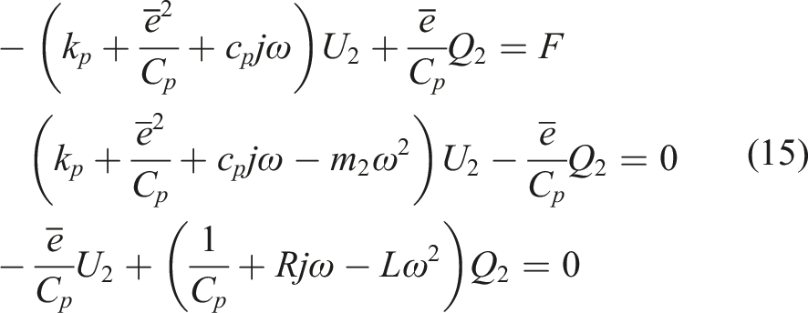
Equation (15) is a nonlinear algebraic equation system of three unknowns L, U2, and Q2, which can be easily solved numerically, to predict the inductance L that minimizes the main structure displacement for any given frequency ω1 = ω’. As an example, a 20% mass reduction of the main mass is assumed, which changes the baseline response, and causes the detuning of the TMD. Solving equation (15) and considering a purely inductive component, thus retaining only the real part of the solution for L, the required inductance that retunes the TMD to the new structural frequency is found to be 588 mH and its effect on the system dynamics is depicted in Figure 10. The “New Baseline” curve refers to the frequency response of the reduced mass baseline structure, the “Detuned TMD” to the frequency response of the short circuit TMD attached to the reduced mass baseline structure, and the “Retuned SATMD” to the frequency response of the SATMD with inductive impedance of 588 mH. As shown in the red dashed line of Figure 10, this inductance level effectively shifts the system anti-resonance, such that it coincides with the new main mass resonance (red dotted line), yielding an almost 20 dB improvement, in comparison with the detuned TMD. Detuned and retuned SATMD.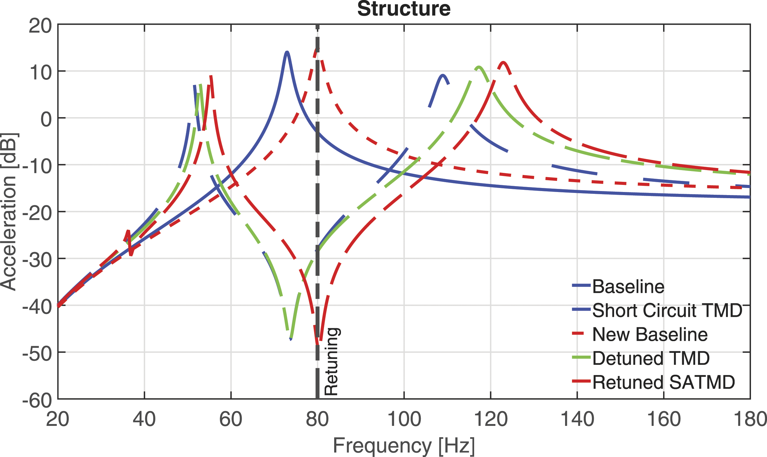
5. Summary and conclusions
A semi-active shunted piezoelectric TMD was introduced in this article, aiming to overcome the major drawbacks of the conventional TMD: the vibration control in a limited frequency range, the lack of multi-modal control capability, and the restricted retuning potential. The theoretical background for the analysis of the shunted piezoelectric TMD was presented for a simplified 1-DOF structural system. An experimental prototype of the electromechanical damper was further developed, using a specialty piezoelectric transducer, and tested on a simplified structural system, using various combinations of resistive and inductive electrical impedance. The experimental results provided excellent validation of the analytical model.
The following main conclusions are summarized based on the obtained analytical and experimental results: Resistive impedance increases the damping capabilities of the coupled electromechanical system because of the dissipation of electrical energy in the shunt resistance, leading up to 7 dB simultaneous acceleration reduction of the structural modes. Inductive impedance introduces a new, highly tunable, oscillator in the system, which enhances the coupling and conversion of kinetic to electrical energy, especially near the bifurcation points. Appropriate inductance tuning results in the practical elimination of each structural mode, and can also lead to multi-modal vibration control, achieving 10 dB reduction. Finally, inductive impedance was found able to retune the resonant frequency of the electromechanical TMD to a changing structural frequency, preventing the detuning of the TMD, and proving the semi-active vibration control abilities of the proposed damper. In summary, the SATMD was found able to compensate for the purely mechanical TMD disadvantages, providing broadband vibration suppression and control to the host structure, and offering great retuning capabilities.
In future investigations of the proposed electromechanical TMD, a wider variety of available shunt impedance equipment, using synthetic inductance and capacitance, combined with an appropriate control algorithm, may exploit the full vibration suppression capabilities of the system.
Footnotes
Declaration of Conflicting Interests
The author(s) declared no potential conflicts of interest with respect to the research, authorship, and/or publication of this article.
Funding
The author(s) disclosed receipt of the following financial support for the research, authorship, and/or publication of this article: This work was funded by the European Union and Greek national funds through the Operational Program Competitiveness, Entrepreneurship and Innovation, under the call RESEARCH – CREATE – INNOVATE (project code: T1EDK-03427, project acronym: TRANVIC). The authors are grateful for this support.