
Abstract
Thermo-acoustic instability occurs when self-excited oscillations are generated due to the coupling between unsteady heat release and acoustics. This phenomenon can result in an increased rate of vibration, structural damage, and produces unwanted emissions. Thermo-acoustic instability occurs in rocket engines, gas turbines, combustors, and furnaces. When thermo-acoustic instability occurs, many modes are developed naturally at a specific point. Some waves are unstable and some are stable. So, to study this phenomenon the most unstable waves are considered and a technique is developed to suppress these unstable waves. A radial air injector as a closed-loop active control method is used for breaking the coupling between the heat waves and acoustics inside the 1D combustion chamber. The distance between the burner and the air injector is varied for the fixed position of the burner with respect to the Rijke tube, that is, x/L = 0.01125, 0.0075, and 0.00375. This closed-loop method works based on the feedback acquired from a microphone. The control method is built using DAQ and Arduino with the LabVIEW as interface for Arduino (LIFA). An air flow rate controller setup is developed to control and measure air required for suppressing the thermo-acoustic instability. Thermo-acoustic instability is effectively suppressed with the help of radial injection in the form of micro-jets at the downstream of the burner as the closed-loop controlling method. It is concluded that when the radial micro-jet air injection plane is closer to the burner head, the thermo-acoustic instability gets suppressed in a short time and with a lesser quantity of air.
1. Introduction
Thermo-acoustics is the interaction between temperature, density, and pressure variations of acoustic waves (Candel, 2002; Kosztin et al., 2013). High levels of sound are produced when a flame is placed in a larger diameter tube or a combustion chamber. The flame excites the fundamental mode or one of the harmonics of the tube or combustion chamber. This can create instabilities in the system and the phenomenon is called thermo-acoustic instability (Deshmukh and Sharma, 2017a; Moeck et al., 2013; Paschereit et al., 1998; Zhao and Li, 2015). These instabilities can cause significant structural damage, which can be commonly observed in jet engines, gas turbines, industrial burners, combustion engines, etc. (Bloxsidge et al., 1988a, 1988b; Cheng, 1985; Hedge et al., 1987; Johnson, 2001; Paschereit et al., 1998; Peracchio and Proscia, 1998; Schadow et al., 1985; Zhao et al., 2018). These instabilities have to be suppressed to improve the thermal efficiency and performance of the combustion system. When suppression of the thermo-acoustic instability takes place, the decoupling between heat release and pressure waves needs to be carried out. This phenomenon was first experimented by Lord Rayleigh, and this led to the development of Rayleigh’s criterion. The Rayleigh criterion states that the addition of heat in phase with acoustics encourages instability whereas if it is added out of phase with acoustics then the instability dampens (Deshmukh and Sharma, 2020; Dowling and Morgans, 2005; Rayleigh, 1878). Deshmukh and Sharma proposed that the co-efficient of Rayleigh index (CRI) plays a major role in measuring the effectiveness of a control system for suppression of thermo-acoustic instability and also evaluated the performance of radial micro-jet injection technique for the same (Deshmukh and Sharma, 2020). It was observed that a decrease in pressure fluctuation by 5 dB in the combustor leads to a reduction in NOx emissions (Dowling and Morgans, 2005).
Thermo-acoustic instability can be suppressed using two methods, that is, passive and active control methods (Zhao et al., 2018). Passive methods help to reduce the instabilities by making hardware changes (Noiray et al., 2007; Steele et al., 2000; Wu et al., 2018; Zalluhoglu and Olgac, 2016). Passive methods work well for a specific range of frequencies and fall short for the rest of the frequencies. Making changes in the hardware design to accommodate other conditions could be time-consuming and costly. This method includes acoustic dampers like the Helmholtz resonator (Deshmukh et al., 2019), quarter-wave tubes (Howard and Craig, 2011), perforated plates (Li et al., 2010), acoustic liners, etc. The active control method was developed to break the coupling between heat release and acoustics with the help of an external energy source (Dowling and Morgans, 2005; Poinsot et al., 1992). The active control method aims to design a controller that can interact with acoustic waves and lead to decaying of the acoustic oscillations. The controller is classified into two types, that is, fixed-parameter controllers and adaptive controllers (Billoud et al., 1992). It could be of two types, namely, open loop and closed loop. Different controllers in active control methods include external acoustic dampers (loudspeakers) (Heckl, 1988), fuel modulation to the combustor (phase-shifting controller) (Heckl, 1988), secondary fuel injection (Annaswamy and Ghoniem, 2002; Hathout et al., 2000; Neumeier, 1996), and releasing air radially inside the combustor (radial air injection system) (Barooah et al., 2003; Deshmukh and Sharma, 2016, 2017a, 2017b, 2020; Marosky et al., 2016).
Radial air injection can be used for decoupling the pressure and unsteady heat release to suppress thermo-acoustic instabilities. Deshmukh and Sharma proposed an open-loop active technique for the suppression of thermo-acoustic instabilities using radial micro-jets (Deshmukh and Sharma, 2017b). In an open-loop technique, human intervention is necessary which provides an upper hand to this research as closed-loop techniques are more advantageous in terms of feedback acquired. In open-loop technique, the air provided to the injector plane is constant which leads to wastage of energy whereas in closed-loop technique only necessary amount of air is supplied according to feedback acquired through the sensors. As additional air is supplied to the combustion chamber in open-loop technique, it leads to increase in weight of the system and sometimes causes the flame to be extinguished. The main goal of this work is to develop a closed-loop radial air injection as active control method to suppress the thermo-acoustic instabilities. The position of plane of radial air injection is crucial to break the coupling. To check the performance of the developed methods, study has been carried out at different positions of radial air injection plane downstream of the burner. The controlled supply of air is based on the feedback from microphone. So, the developed system can be effectively used in any application without human intervention.
2. Experimental setup
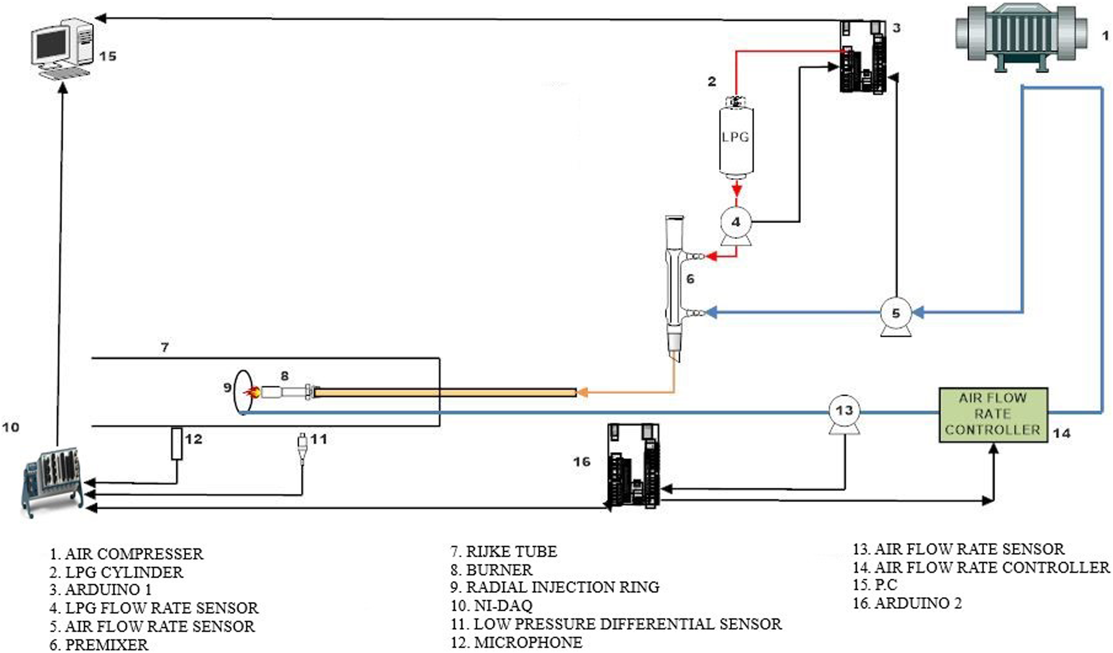
The photograph of the developed active closed-loop control method to suppress thermo-acoustic instability is shown in Figure 1. The schematic diagram of the control system is shown in Figure 2. The air in the compressor is compressed, and then passed through the moisture separator, filter element, and air dryer, where the compressed air is filtered and dried. It is then stored in an air reservoir tank for experimental work. The rotameter controls the amount of air required and is sent to the premixer. Liquified Petroleum Gas (LPG) from a cylinder is passed through the LPG rotameter which controls the quantity of LPG supplied to the premixer. The function of the premixer is to mix the LPG and the compressed air completely. This mixture is then sent to the burner via an aluminium tube. When thermo-acoustic instability is developed due to presence of premixed flame inside the Rijke tube, the sound pressure levels (SPL) are detected by the Onosokki MI-3111 microphone with the help of Data acquisition system of National Instrument (DAQ NI-9234). The microphone is positioned about 0.20 m away from the Rijke tube, to avoid damage of the microphone. Control method actuation is based on signal from the microphone, which is in interface with LabVIEW. Arduino is used to acquire signals from the air flow rate sensor and microphone. Based on requirements of radial air injection, arduino provides signals to the stepper motor. The stepper motor requires Pulse Width Modulation (PWM) signals for actuation which is best provided using an Arduino PWM output. The analog signals from the air flow rate sensor are acquired easily and reliably using an Arduino. The acquired signals in Arduino from the air flow rate sensor are processed and sent to LabVIEW software by using a bridge called LabVIEW Interface for Arduino, and the actuation signals for stepper motor is provided by LabVIEW to Arduino which makes the stepper motor rotate in steps to controlled a needle valve. The measured and control air is sent to the radial injection tube to suppress the instability. Each micro-step of the stepper motor corresponds to the flow rate depending upon the different pressure levels that had to be calibrated precisely. The reference acoustic pressure level based on acquired background sound has been set as 4 Pa. If the pressure exceeds a certain limit, a command is issued by the Arduino to the stepper motor (in micro-steps of 1.8°) which in turn rotates the needle valve, sending the air to the concentric copper ring injector setup. An air flow rate sensor (Omron D6F20A6-000) is used to measure the flow rate before supplying to the radial copper tube. Setup of the control system. Line diagram of the control system.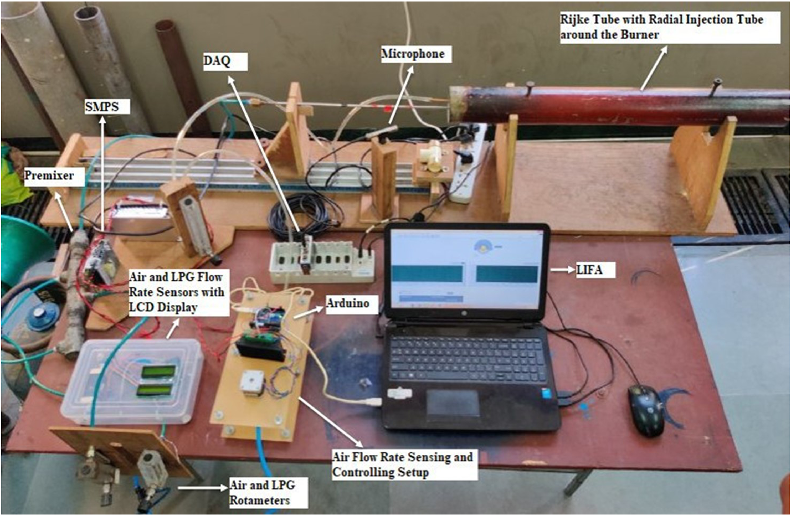
The concentric copper ring injector setup comprises of a copper tube which has a 90° circular bend at one end. The circular bend has 12 small circular holes that have been used for releasing air in the form of micro-jets. The circular bend is placed concentric to the downstream of burner head. All 12 micro-jets inject the air in one plane with the help of this copper tube. The plane of radial injection can be varied downstream of burner head based on requirements. The process continues until the threshold pressure is achieved after which the air flow to the needle valve stops.
3. Methodology
The experimentations were performed for different distances between the burner head and the radial air injection plane. In the beginning, the position of the burner with respect to the Rijke tube was confirmed based on the highest SPL acquired from the microphone. The burner position was fixed as b/L = 0.16, where b is the position of burner with respect to the Rijke tube and L is the length of the Rijke tube. The radial air injector plane is positioned to the downstream of the burner. The position of burner is decided according to x/L = 0.01125, 0.0075, and 0.00375 where x is the distance between the burner head and micro-jet radial air injection plane as shown in Figure 3, and L is the length of the Rijke tube. The diameter of the radial air injection ring is 0.065 m, so that it can move easily inside the Rijke Tube. For creating 12 micro-jets, 12 holes of 1 × 10⁻³ m diameter at an angle of 30° are drilled. The experiments were carried at an air-fuel ratio of approximately 50. The air and LPG flow rate were 10 Liters per minute (LPM) and 0.2 Liters per minute (LPM), respectively. Calculated fundamental frequency was 218.75 Hz (C/2L, where C is the velocity of sound and L is the length of Rijke tube) for 0.8 m length of the Rijke tube. The equivalence ratio is defined as the ratio of the actual air/fuel ratio to the stoichiometric air ratio, and it is denoted by Φ. The instability was observed for lean air–fuel mixture with an equivalence ratio of Φ = 0.56. The frequency of observed thermo-acoustic instability lies in the range of 640 Hz–660 Hz, which is close to the third mode (218.75 × 3 = 656.25 Hz). For suppression of these thermo-acoustic instabilities, the control strategy was developed. The supply of air to the radial air injection ring passes through a controller which alters the flow rate of air to the injector with every iteration until thermo-acoustic instability is suppressed based on feedback from the microphone. The values obtained from the sensor are Fast Fourier transformed and then converted to SPLs in dB using calibration factors. Relative position of the burner and the plane of radial air injection.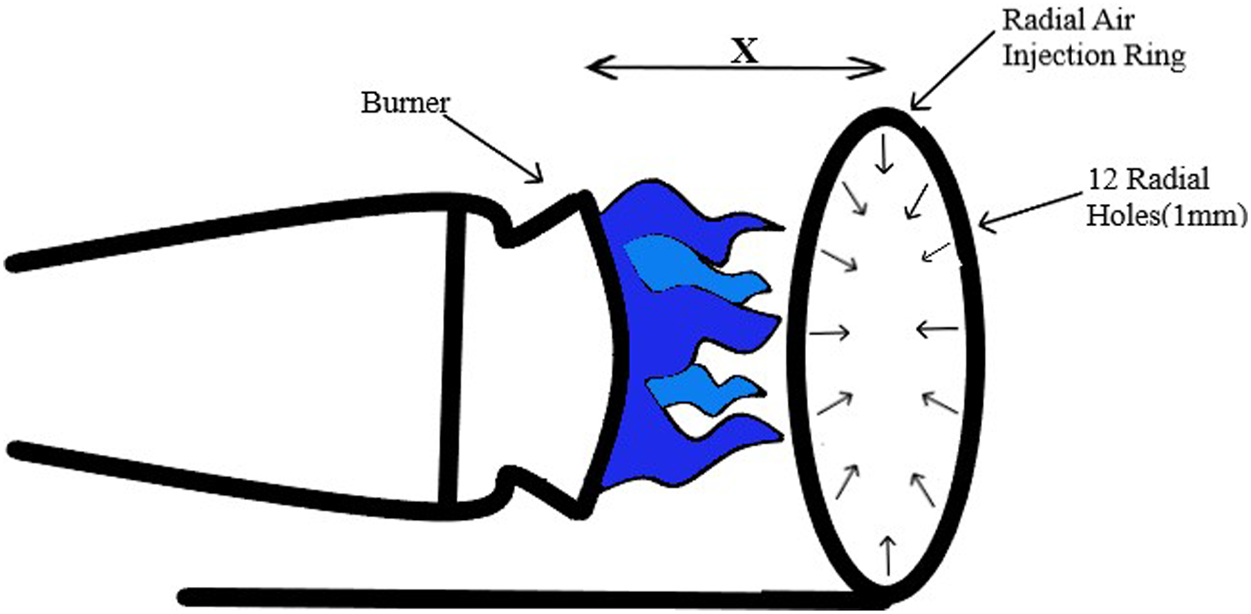
4. Data processing
Data obtained from microphone and air flow sensor were processed for getting different plots. To check the effectiveness of the feedback system, these plots are essentials. Four different plots obtained after processing the data are as follows.
4.1. Raw signal reading
Raw signal readings were acquired by the microphone, and the readings were obtained as sound pressure in Pascal. The effect of radial air injection as a control method can be seen by plotting sound pressure variation with time.
4.2. Air flow rate sensor reading
The amount of air released in the radial air injection ring to suppress the instabilities was obtained using the Omron air flow rate sensor in terms of voltage. The obtained data are multiplied by calibration factor to get the output in LPM. The flow rate (LPM) variation with time can be plotted from these data.
4.3. Positive peak reading
The raw signal readings were obtained and LabVIEW was conditioned to give only the positive sound pressure peak readings of the raw signals. The positive sound pressure peak variation with time can be plotted.
4.4. FFT reading
The obtained sound pressure (Pa) values were conditioned in the LabVIEW software using Fast Fourier Transformation. The sound pressure output was then converted into SPL in dB using the formula.
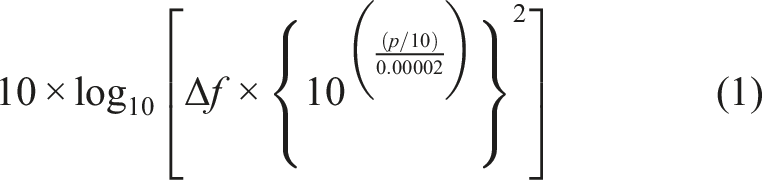
The SPL variation with frequency can be plotted from these data.
As explained above, data were obtained and processed for different x/L values and effectiveness of control method were evaluated which is discussed in the next section.
5. Result and discussion
5.1. Results of radial injection at x/L = 0.01125
Figure 4(a) shows the real time signals with the closed-loop method. It was observed that the maximum sound pressure (Pa) attained was close to 12 Pa and after suppression the sound pressure reaches close to 0 Pa. The time taken for suppression of instability was around 30 s. Figure 4(b) shows the air flow rate readings. Initially, the rate of air supplied to the injector plane was close to 0 LPM, and after 30 s, the rate of air supplied was around 7 LPM. There was no further increase in flow rate which indicated that there is no instability in the system. Figure 4(c) shows positive peaks obtained from LabVIEW. From the figure, it is very clear that after 32 s complete suppression of instability is achieved from 12 Pa to close to 1 Pa. The time required for suppression corresponding to Figure 4(a) and (c) is close to 32 s. In Figure 4(d), instability was observed at a peak SPL of 107 dB corresponding to a frequency of 640 Hz. This is comparative frequency spectra, where the comparison is made based on actual instability, with control methods and background sound level. Around 40 dB reduction was achieved using the control method. After suppression of instability, the SPL was observed close to 68 dB. Results of radial injection at x/L = 0.01125: (a) real time signals with the closed-loop method, (b) air flow rate sensor readings, (c) positive peak obtained, and (d) competitive frequency spectra for the third mode of instability.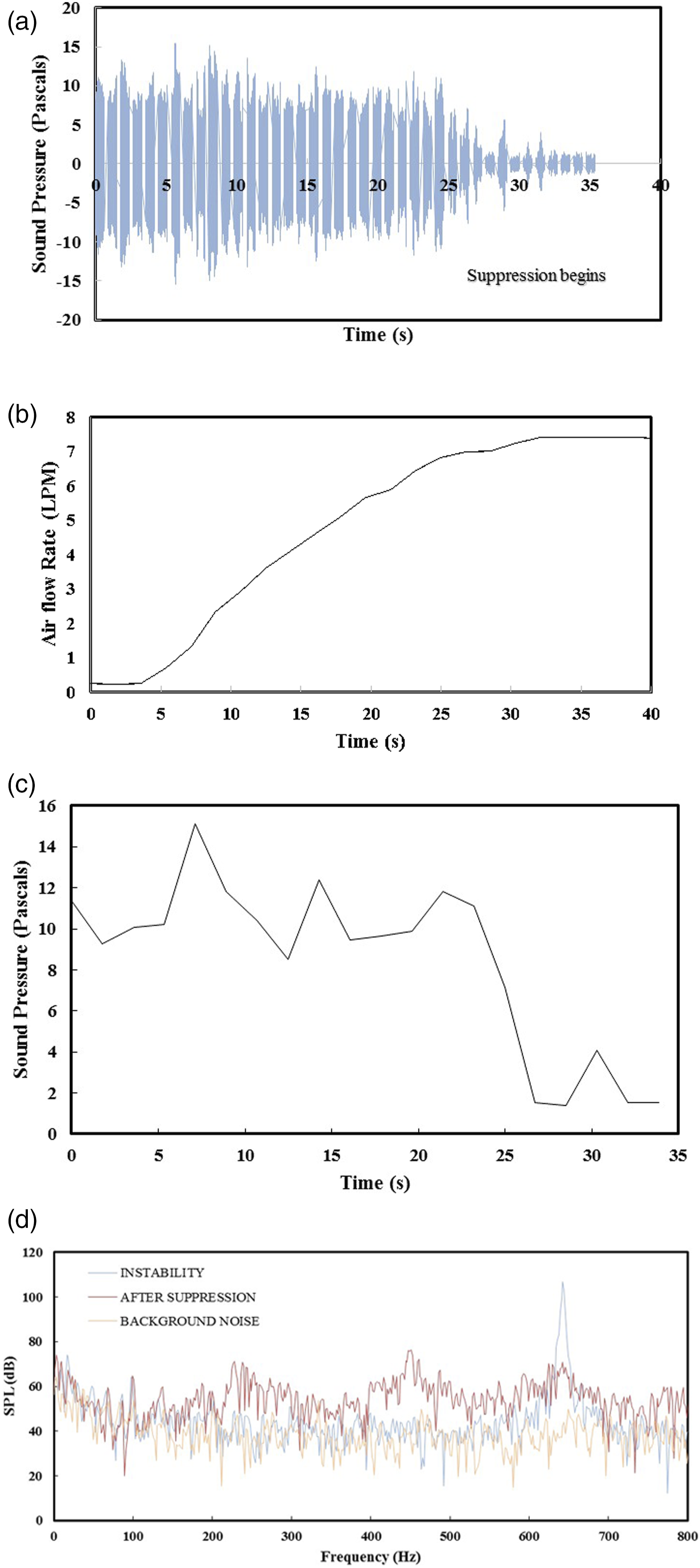
5.2. Results of radial injection at x/L = 0.0075
Figure 5(a) shows the real time signals with the closed-loop method. It was observed that the maximum SPL (Pa) attained was around 7 Pa, and after suppression, the sound pressure reaches close to 0 Pa. The time taken for suppression of instability was around 20 s. Figure 5(b) shows the air flow rate readings. Initially, the flow rate of air supplied to the injector ring was close to 0.5 LPM, and after 20 s, the rate of air supplied was 3.5 LPM. There was no further increase in the flow rate which indicated that there is no instability in the system. Figure 5(c) shows positive peaks obtained from LabVIEW and complete suppression of instability from 7 Pa to close to 0 Pa. The time required for suppression corresponding to Figure 5(a) and (c) is close to 21.5 s. The time instant of Figure 5(b) indicates quantity of air supplied for suppression of thermo-acoustic instability, whereas Figure 5(c) shows reduction in instability pressure with increase in quantity of air. In Figure 5(d), instability was observed at a peak SPL of 104.25 dB corresponding to a frequency of 660 Hz. After suppression of instability, the SPL corresponding to 660 Hz frequency was 48.58 dB which was close to the background noise. Around 56 dB reduction in SPL was achieved with the control method. Results of radial injection at x/L = 0.0075: (a) real time signals with the closed-loop method, (b) air flow rate sensor readings, (c) positive peak obtained, and (d) competitive frequency spectra for the third mode of instability.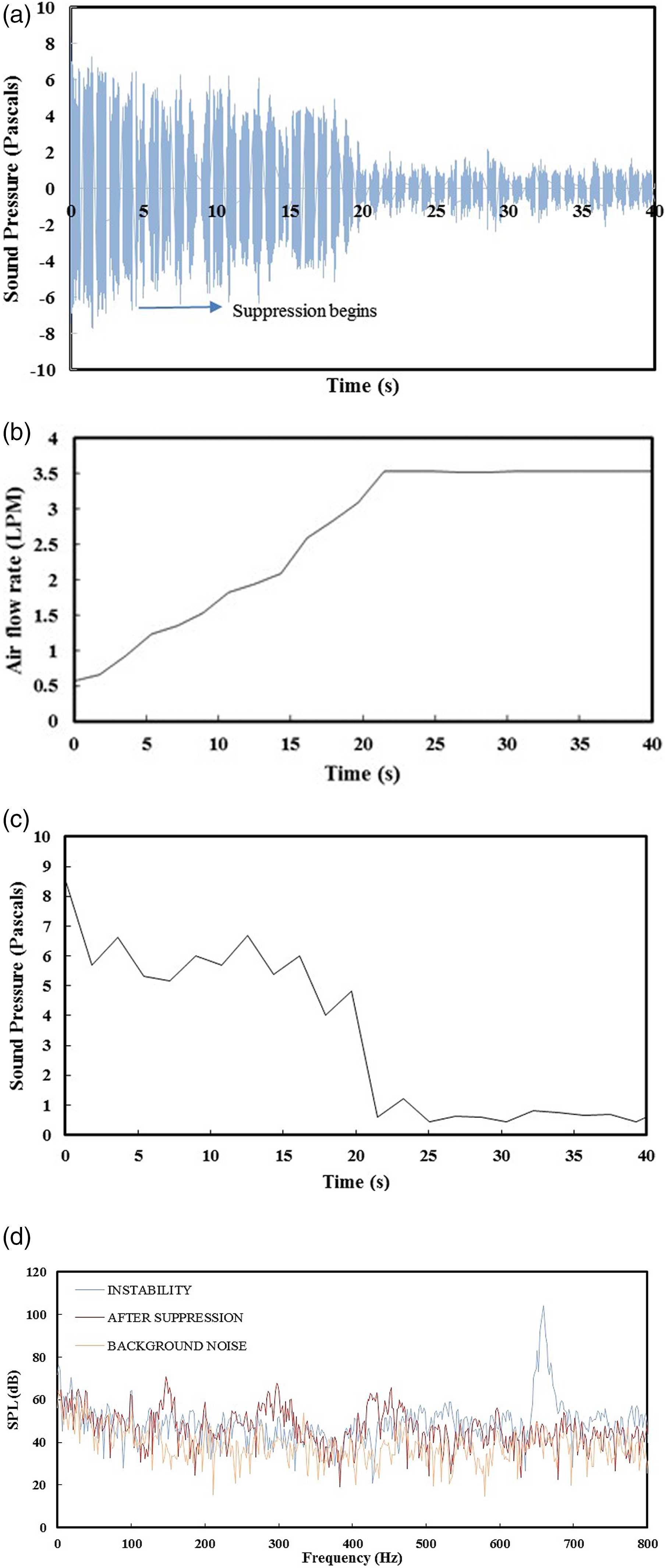
5.3. Results of radial injection at x/L = 0.00375
Figure 6(a) shows the real time signals with the closed-loop method. It was observed that the maximum sound pressure (Pa) attained was around 8 Pa, and after suppression, the sound pressure reaches close to 0 Pa. The time taken for suppression of instability was around 10 s. Figure 6(b) shows the air flow rate readings. Initially, the rate of air supplied to the injector plane was close to 0.6 LPM, and after approximately 10 s, the rate of air supplied was 1.2 LPM. There was no further increase in flow rate which indicated that there was no instability in the system. Figure 6(c) shows positive peaks obtained from LabVIEW and suppression of instability from 8 Pa to close to 0 Pa. The time required for suppression corresponding to Figure 6(a) and (c) is close to 10.7 s. In Figure 6(d), instability was observed at a peak SPL close to 103 dB corresponding to a frequency of 645 Hz. After suppression of instability, the sound pressure corresponding to 645 Hz frequency was 39 dB which was close to the background noise (i.e., 38 dB). Total reduction in SPL is around 62 dB which is the highest and corresponds to the complete suppression of the instability. Results of radial injection at x/L = 0.00375: (a) real time signals with the closed-loop method, (b) air flow rate sensor readings, (c) positive peak obtained, and (d) competitive frequency spectra for the third mode of instability.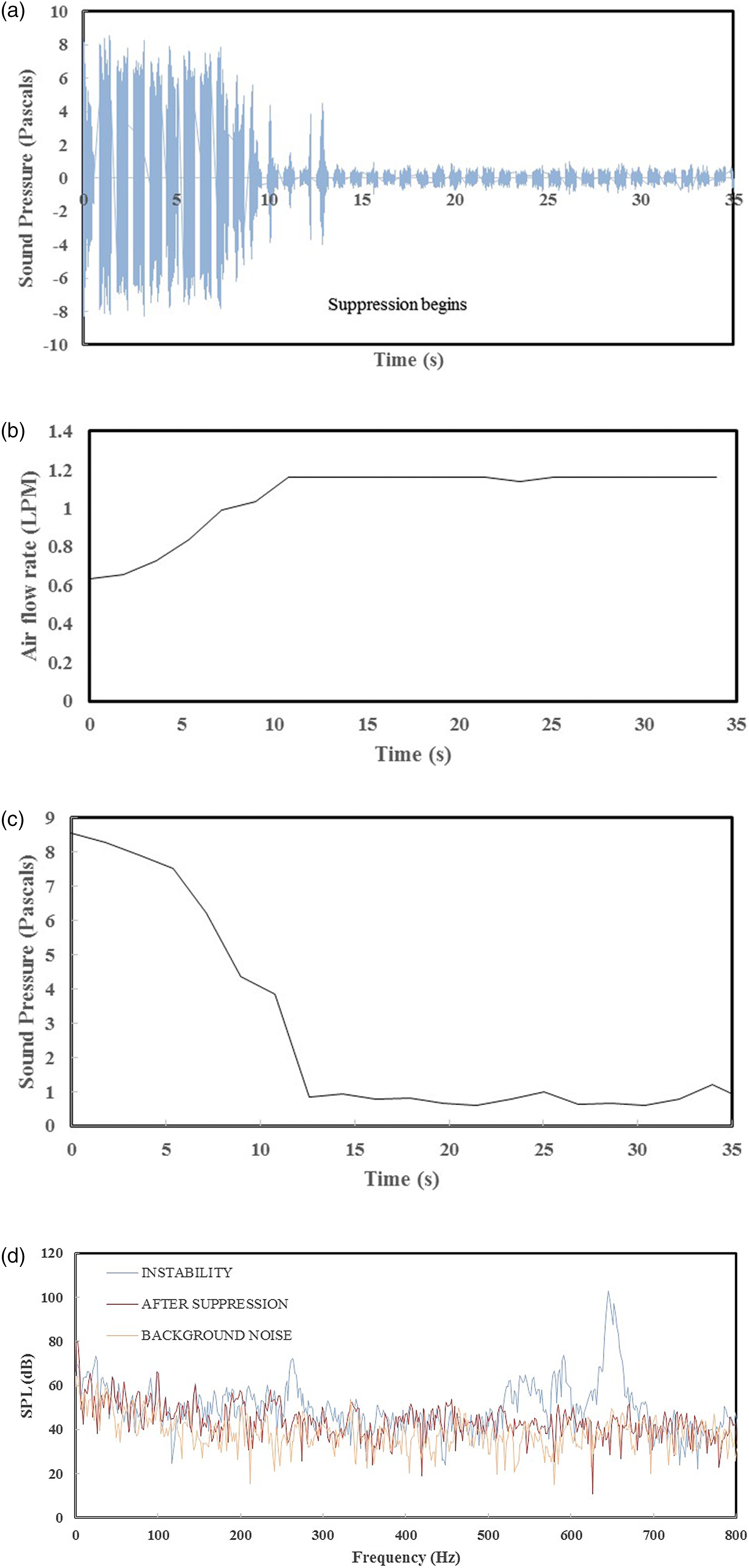
5.4. Comparative results of position of radial injection plane
The comparative plot of effectiveness of the active control method for different positions of radial air injection is shown in Figure 7. To suppress the instability completely, radial jets should be able to interact with the flame. With radial injection close to the burner head, complete suppression of thermo-acoustic instability was achieved. With the position of the radial air injection plane close to the burner head, time required for suppression reduces to 66% compared to x/L = 0.01125. Similarly, air flow rate required for complete suppression reduces to 84%. The active closed-loop control method with the radial plane of air injection near to burner works in short time span and with lesser energy input. The interaction between the flame and injection plane is responsible for decoupling the pressure wave and unsteady heat release. With low flow rate, velocity of radial micro-jets reduces. With the control method close to the burner head, low velocity jets actively reduce the instability. The reduction in time and flow rate is very important for applying the control method to any power producing devices. Larger the time for suppression, higher are the chances of failure of the control module and structure. Whereas reduction in air flow rate reduces overall weight of the system, energy, and chances of blowing off flame. Comparative results of position of radial injection plane: (a) time required and (b) air flow required.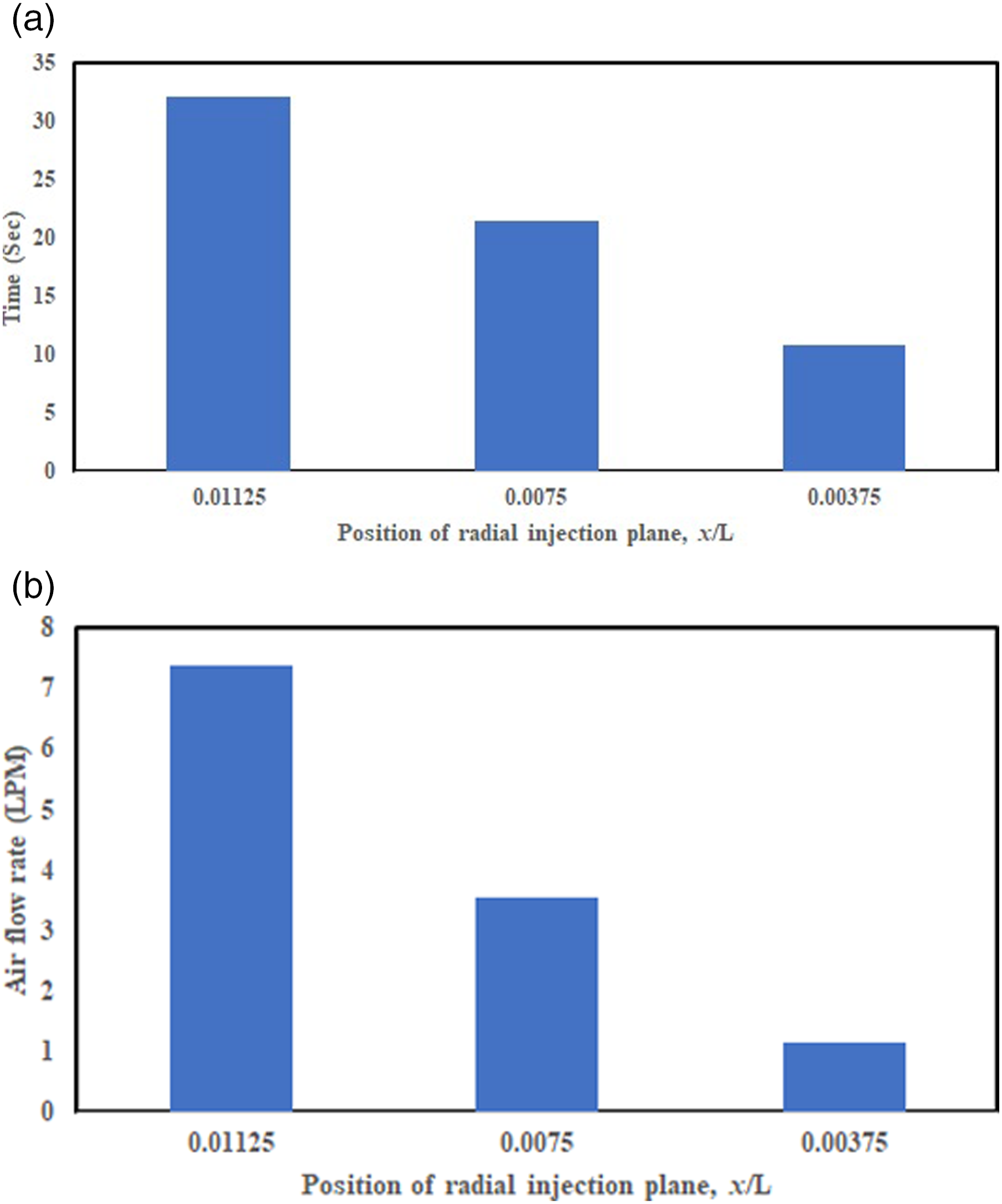
6. Conclusions
In this study, use of the closed-loop active control method has been successfully demonstrated to monitor and suppress an unstable combustion system of a Rijke tube experimentally. Based on initial experiments, the third mode of instability was observed for a lean mixture. Based on an identified mode and acquired background sound level, a control strategy was designed and implemented to suppress instability completely. To evaluate the performance of the control method, the position of radial air injection was varied. Based on this, it is concluded that the plane of radial air injection should be close to burner for effective control of instability. Radial micro-jets were very effective for altering the phase angle between the heat release and acoustics in the Rijke tube. Using the radial injection plane close to the burner, the low flow rate which results in low velocity jets has also been very effective in bringing the SPL close to the background level in short span of time. The complete suppression of thermo-acoustic instability using this active closed-loop method is possible without human interference. Therefore, the developed control method can be applied to any power producing devices effectively, which may result in improving combustion efficiency and improving overall performance of the system.
Footnotes
Declaration of conflicting interests
The author(s) declared no potential conflicts of interest with respect to the research, authorship, and/or publication of this article.
Funding
The author(s) received no financial support for the research, authorship, and/or publication of this article.