
Abstract
The bearings are important paths for the shaft vibration transmitting to the hull structure. A new scenario based on non-contact electromagnetic actuators mounted at bearing pedestals is proposed to suppress the vibration transmission from the shaft to the elastic foundation. The dynamic model of a shafting system with the non-contact electromagnetic actuators is established on the Hamilton’s principle. With this model, the influence of the displacement stiffnesses of the electromagnetic actuators on the vibration transmission is discussed, and the feasibility of active control is investigated. A multi-harmonic vibration suppression method is adopted and the performance is evaluated. Numerical results show that the vertical control by the electromagnetic actuators is able to attenuate the vibration transmission from the shaft to the foundation. With the addition of horizontal control, the foundation vibration is further decreased due to the reduction of power flow generated by the moments between the bearing pedestals and foundation. The results of a proof-of-principle experiment have also verified the effectiveness of the vertical control by the non-contact electromagnetic actuators in vibration transmission suppression and the foundation acceleration responses are remarkably reduced.
Keywords
1. Introduction
The fluctuating forces induced by the propeller rotating in the non-uniform wake can transmit to the hull structure via the propulsion shafting system and cause low-frequency acoustic radiation (Qu et al., 2017). The shaft vibration transmits to the hull via bearing pedestals, which constitutes an important part of the radiated sound (Chen et al., 2019). Therefore, it is necessary to suppress the vibration transmission at the bearing pedestals in the shafting system.
Passive vibration control has gained popularity since there is no need for inputting extra energy into the control devices (Goodwin, 1960; Huang et al., 2018; Liu et al., 2018). But since the natural frequency of the passive devices cannot be arbitrarily low, the effect of suppressing low-frequency vibration is not obvious, while active control can attenuate low-frequency vibration by utilizing active control algorithms and elements (Xie et al., 2021a; Zheng et al., 2019).
In fact, active vibration control has been widely employed in the rotor systems. Active magnetic bearing (Jiang et al., 2015), active magnetic damper (Bonfitto et al., 2016) and piezoelectric actuator (Sloetjes and De Boer, 2008) have been used as active control elements. Roy et al. (2016) proposed a proportional and high-frequency band limited derivative control law to elicit viscoelastic behavior of an active magnetic bearing, which decreases the rotor response caused by the unbalance. Yao et al. (2017) used an active magnetic exciter and a self-optimizing control method to suppress the rotor vibration and the effectiveness of the proposed scheme is proved by experiments. Zaccardo and Buckner (2021) employed an active magnetic damper to suppress the vibration of a high-speed rotor, which is more effective than the squeeze film damper. Brahem et al. (2020) used piezoelectric actuators to reduce the lateral vibration of a rotor-bearing system, where piezoelectric patches are mounted on the shaft surface to counteract the rotor deformation. But it is worth pointing out that the above investigations are focused on the rotor vibration control instead of the vibration transmission suppression from the rotor to its foundation.
Active vibration control has been used in shafting systems to suppress the vibration transmission from the shaft to the hull. Lewis and Allaire (1987), Lewis et al. (1989) proposed an auxiliary electromagnetic bearing situated near the thrust bearing to suppress the dynamic force between the shaft and thrust bearing through closed-loop feedback control. Baz et al. (1990) used a pneumatic servo-controller to suppress the longitudinal vibration in a shafting system, and the amplitude is reduced by approximately 11 dB over 0–10 Hz. Qin et al. (2020) proposed auxiliary electromagnetic suspension to suppress the friction-induced vibration by reducing the load of the stern bearing in a shafting system. Xie et al. (2021b, 2022) proposed an active stern support combined with active control algorithms to suppress lateral vibration transmission in a shaft-hull system. Zhu et al. (2021) proposed an active orthogonal support mounted between the stern bearing and the hull to suppress the vibration transmission from the shaft to the hull with local velocity feedback control. The present studies are mainly focused on the vibration transmission control at the stern and thrust bearings in a shafting system. However, the vibration transmission via the intermediate bearings cannot be ignored, and the current work rarely involves the vibration transmission suppression at the intermediate bearings. The aforementioned active control scenarios utilized at the stern bearing as well as the thrust bearing cannot be directly applied to the intermediate bearing since the bearings are connected to the hull in different ways. Therefore, investigations on the vibration transmission control at the intermediate bearings are necessary.
In this paper, a new scenario based on non-contact electromagnetic actuators mounted at pedestals of intermediate bearings is proposed to suppress the vibration transmission in a shafting system. The dynamic model of the shafting system with electromagnetic actuators is formulated with the Hamilton’s principle. Using this model, the feasibility of active control is investigated. The performance of the electromagnetic actuators is numerically evaluated and experimentally verified with a multi-harmonic vibration suppression method.
The rest of this paper is arranged as follows. The dynamic model of the shafting system with the non-contact electromagnetic actuators is established in Section 2. The multi-harmonic vibration suppression method is given in Section 3. Numerical simulation of the non-contact electromagnetic actuators in vibration suppression is presented in Section 4. A proof-of-principle experiment to verify the effectiveness of the electromagnetic actuators is given in Section 5. Finally, conclusions are summarized in Section 6.
2. Modelling of the shafting system with non-contact electromagnetic actuators
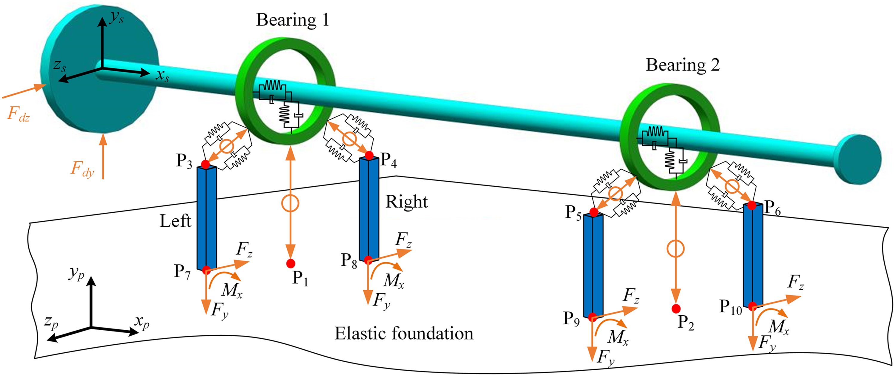
The schematic of the shafting system is shown in Figure 1(a), where The schematic of the shafting system with non-contact electromagnetic actuators (a) The shafting system (b) Schematic of the non-contact electromagnetic actuator.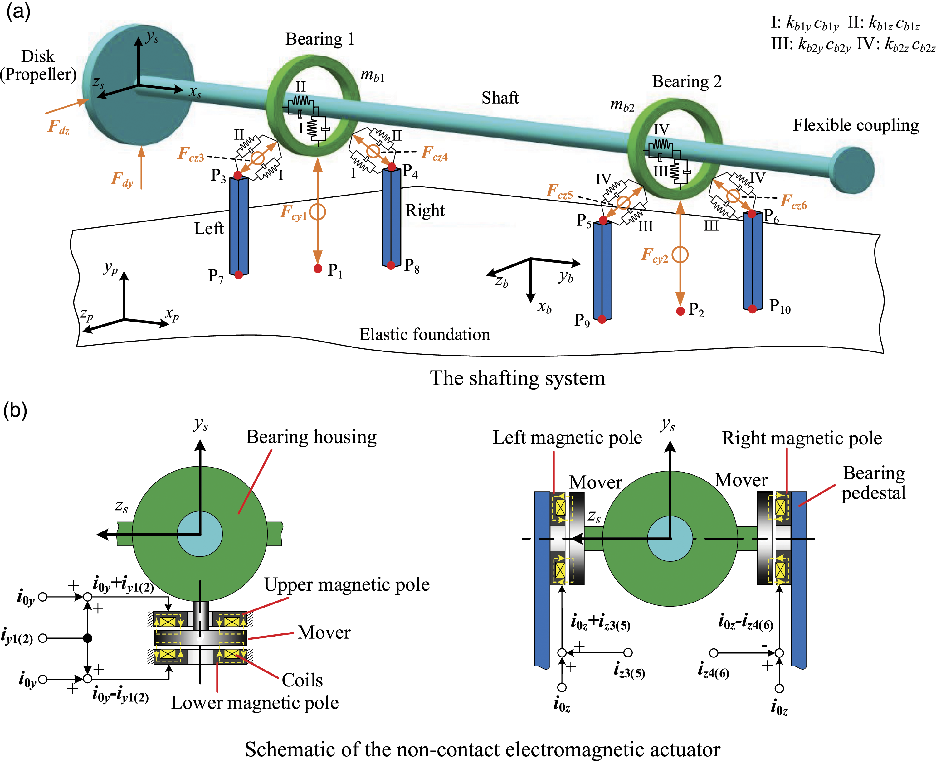
The shaft is represented by a beam of circular cross-section while the elastic foundation by a four-sided simply supported plate. The bearings are simplified to vertical spring-damper elements
The electromagnetic actuators are represented by electromagnetic forces
2.1. Modelling of the non-contact electromagnetic actuator
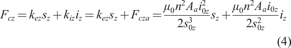
In the electromagnetic actuator shown in Figure 1(b), the vertical poles are driven in differential mode, where one pole is driven by the sum of the bias current and the control current while the opposite by the difference. The total vertical electromagnetic forces can be expressed as (Schweitzer and Maslen, 2009)
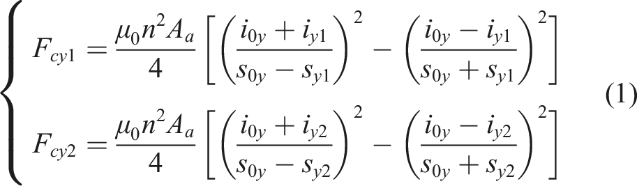
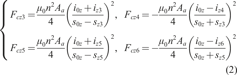
However, the bias currents in the horizontal poles are the same, but the control currents are different. The horizontal electromagnetic forces can be expressed as
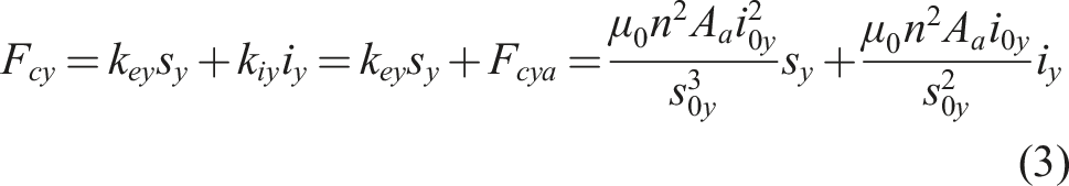
The electromagnetic forces can be linearized at the equilibrium position by taking their partial derivative with respect to
2.2. Modelling of the shafting system
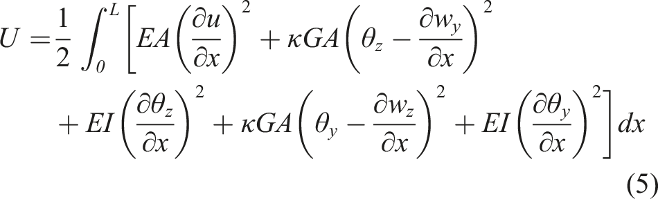
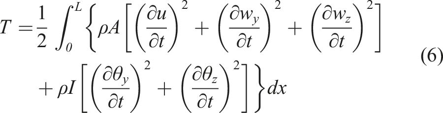
(1) Timoshenko beam - modelling of the shaft and the bearing pedestals
The strain energy
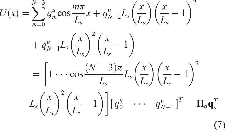
Let
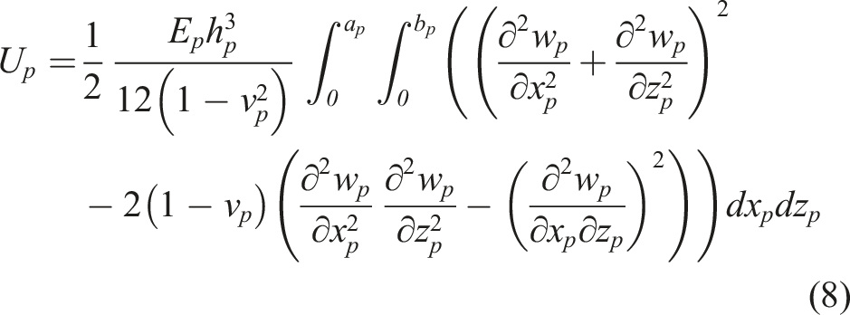
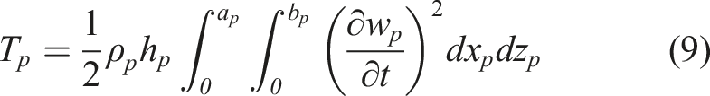
(2) The Kirchhoff plate - modelling of the elastic foundation
According to the Kirchhoff plate theory, the strain energy U
p
and kinetic energy T
p
of the plate at any instant in the coordinate system (o
p
x
p
y
p
z
p
) can be expressed as (Chakraverty and Pradhan, 2014)
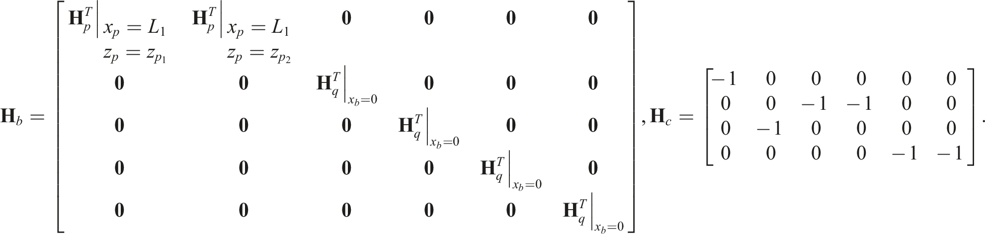
(3) The governing equation of the whole system
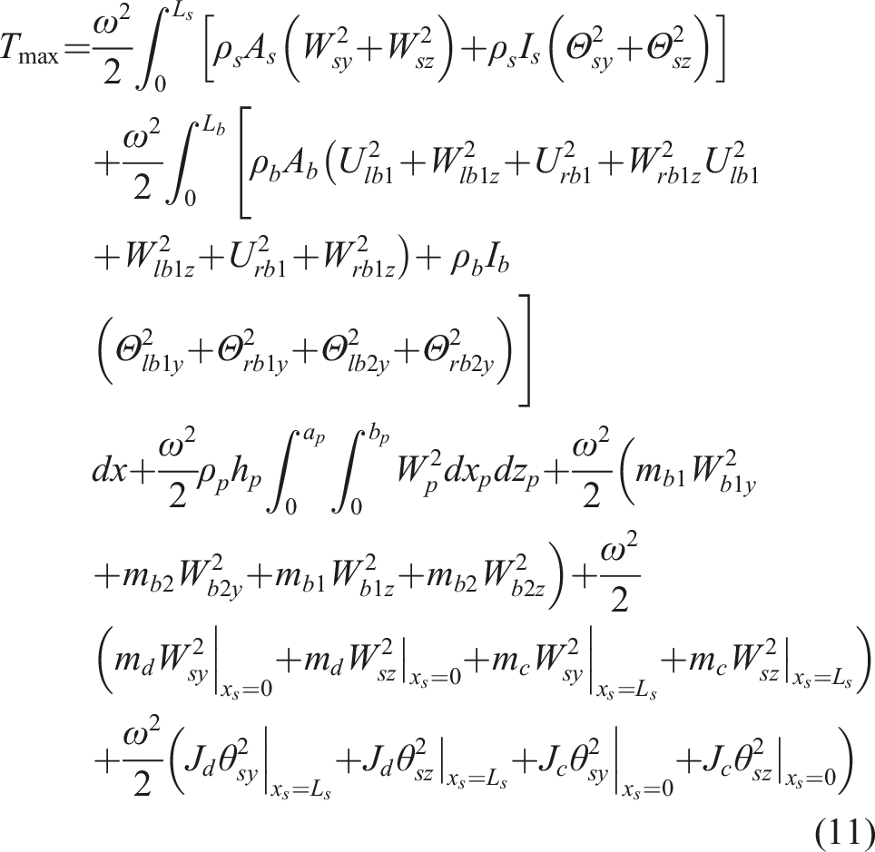
Since lateral vibration transmission is investigated in the system, only the lateral vibration of the shaft, the axial vibration and the lateral vibration in the horizontal direction and around the longitudinal direction of the pedestals are considered. For the whole system, the maximum kinetic energy
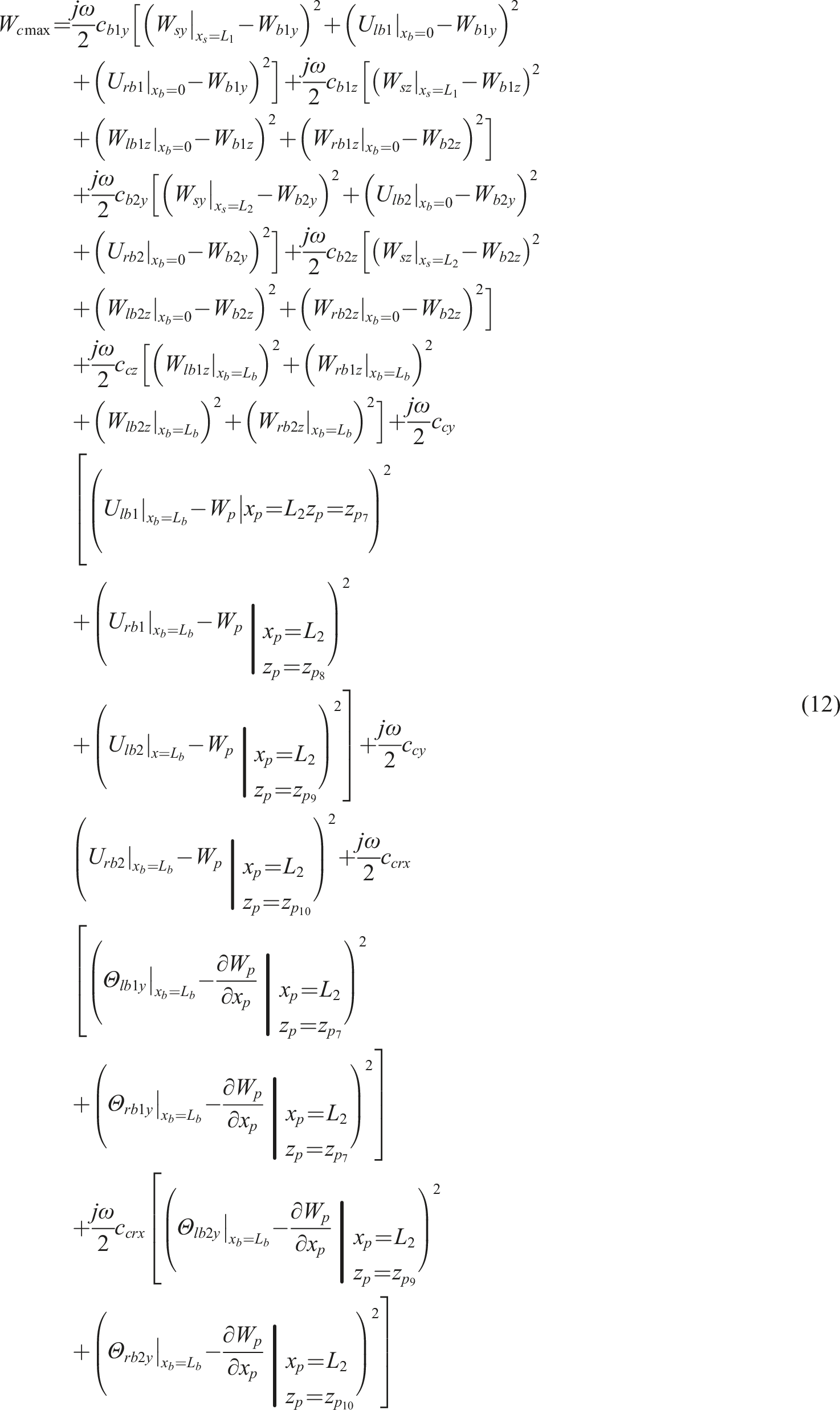
The maximum dissipation energy
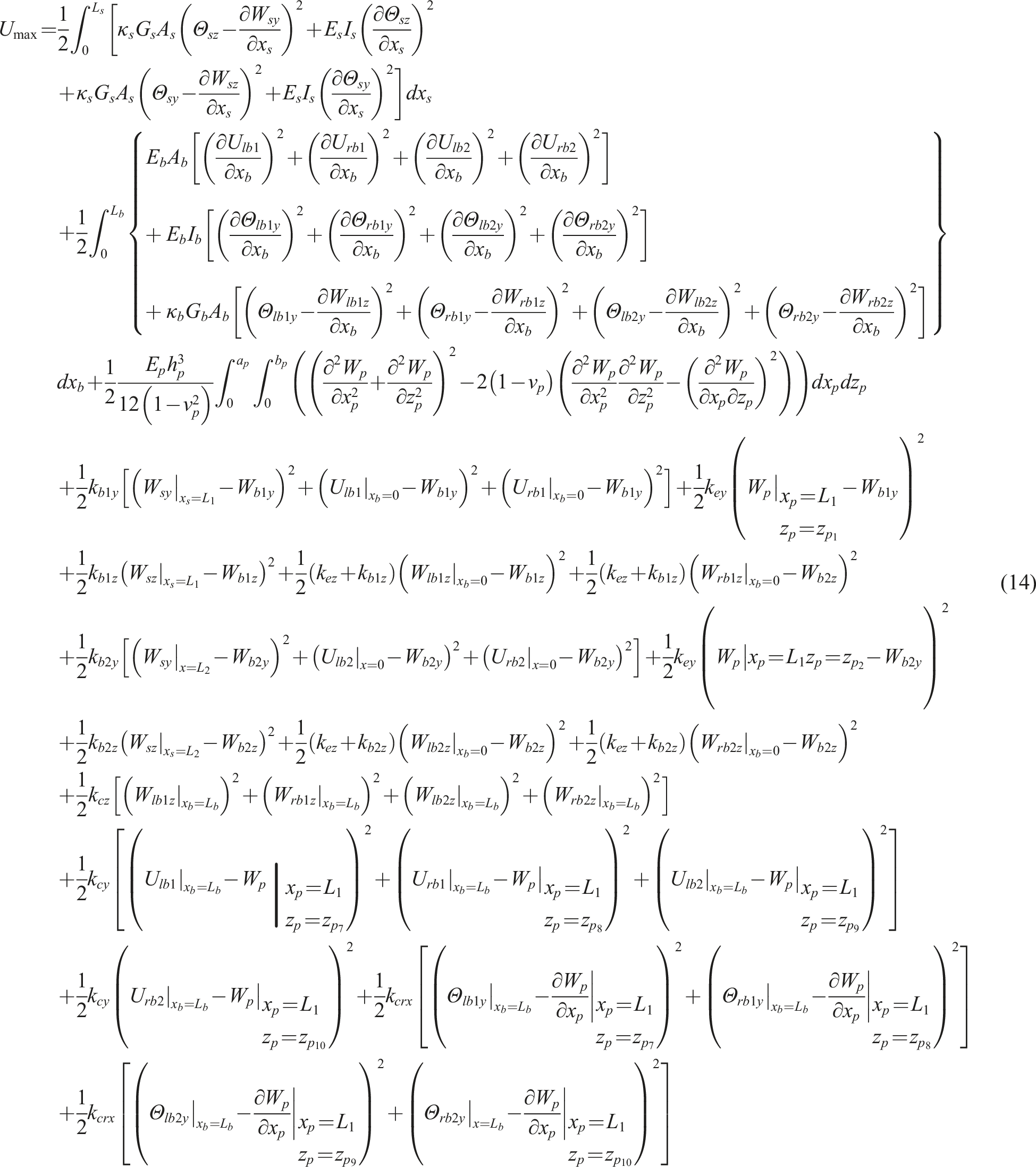
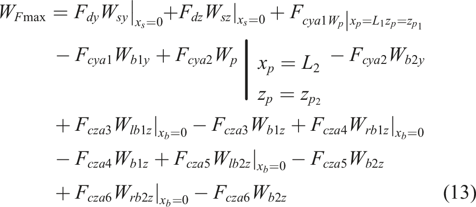
The maximum potential energy
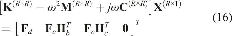
According to the Hamilton’s principle

The system responses can be acquired by solving these linear equations.
3. Multi-harmonic vibration suppression method
In the active control, P1–P6 are the error points. The vertical acceleration of P1, P2 and horizontal acceleration of P3, P4, P5, P6 are the error responses labelled as ay1, ay2, az3, az4, az5, az6. Bias currents are first sent to the magnetic poles and the displacement stiffnesses are determined. And then, when
There have been many active control algorithms put forward for vibration control, which include internal model control, robust control, adaptive control, etc. In order to suppress the multi-harmonic disturbance at the disk, an adaptive control method considering disturbance reconstruction and cross-coupling between control channels is utilized.
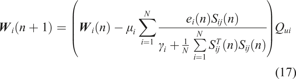
The schematic of a two-channel adaptive control method is shown in Figure 2, where the error responses ay1 and ay2 are reduced by the vertical control forces. To update the adaptive controller coefficients, the normalized LMS algorithm is utilized, which is based on the principle of the steepest descent, uses the square value of the instantaneous error to replace the stochastic gradient of the mean square error and is an adaptive filtering algorithm (Bjarnason, 1995). The ith adaptive controller coefficients W
i
can be expressed as (Wang et al., 2016) Schematic of a two-channel adaptive control method.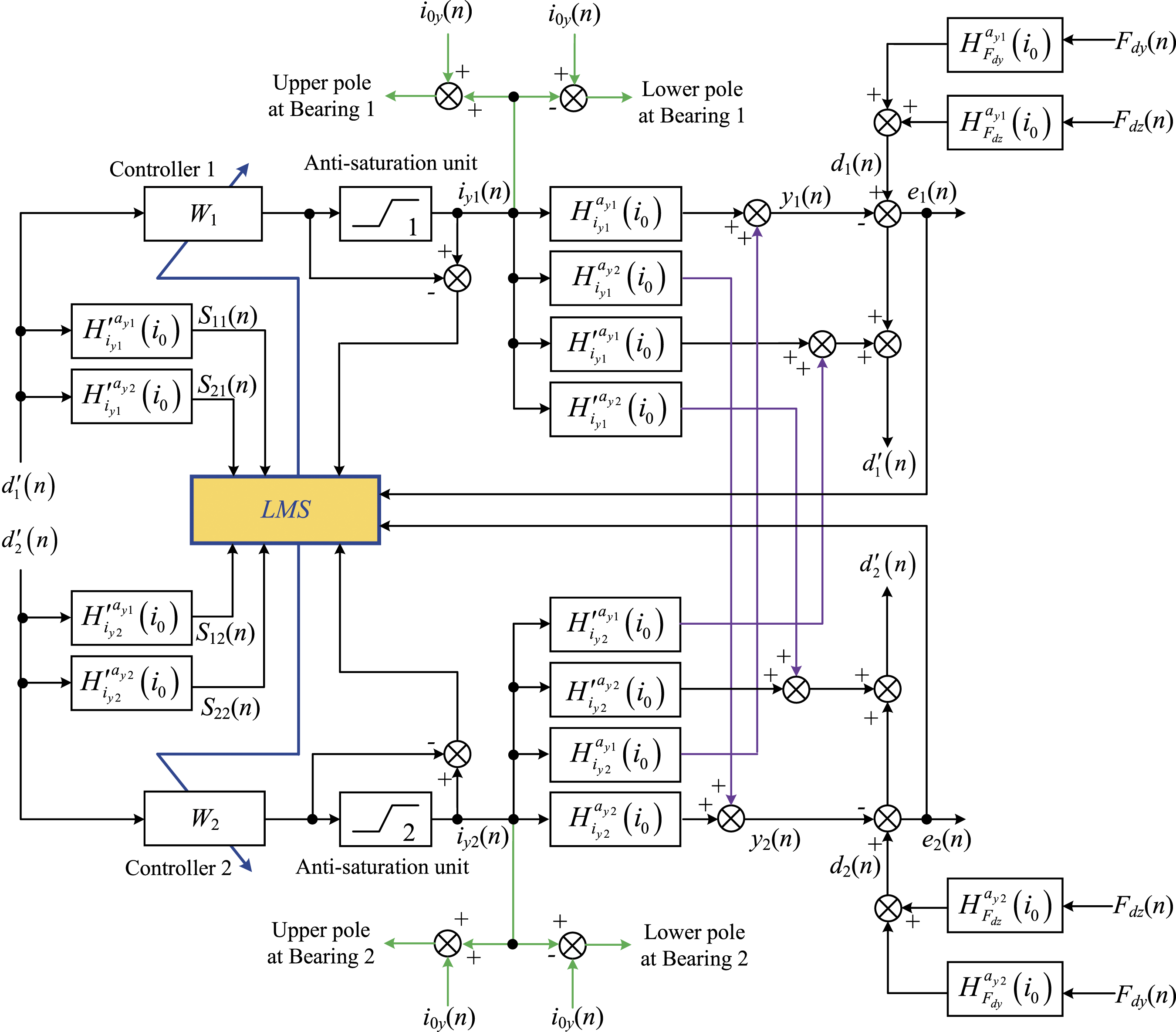
4. Numerical simulation
Parameters of the shafting system with the electromagnetic actuator.
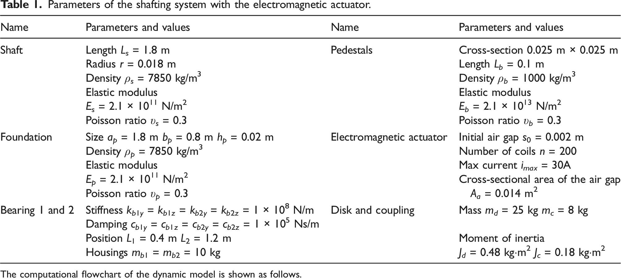
The computational flowchart of the dynamic model is shown as follows.
4.1. Adjustment of displacement stiffnesses
In the active control, bias currents are first sent to the magnetic poles. According to Equations (3) and (4), as the bias currents Variation of displacement stiffnesses with the change of the bias current.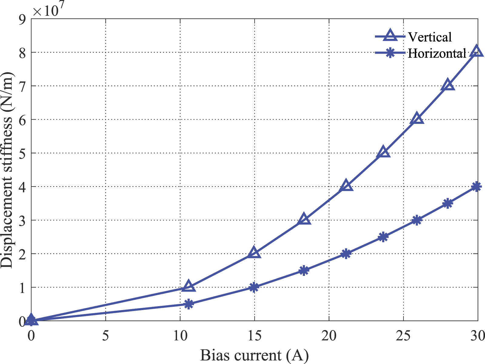
The unit vertical and horizontal disturbance forces are applied at the disk. Supposing the displacement stiffnesses The error responses 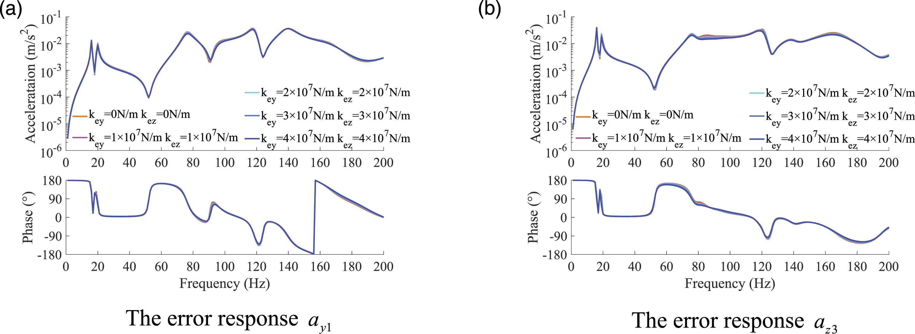
4.2. Active vibration suppression
In the active control, the displacement stiffnesses
To analyze the vibration transmission characteristics of the shafting system, the FRF curves of The FRF curves and the mode shape at 139 Hz (a) The FRF curves (b) The mode shape at 139 Hz.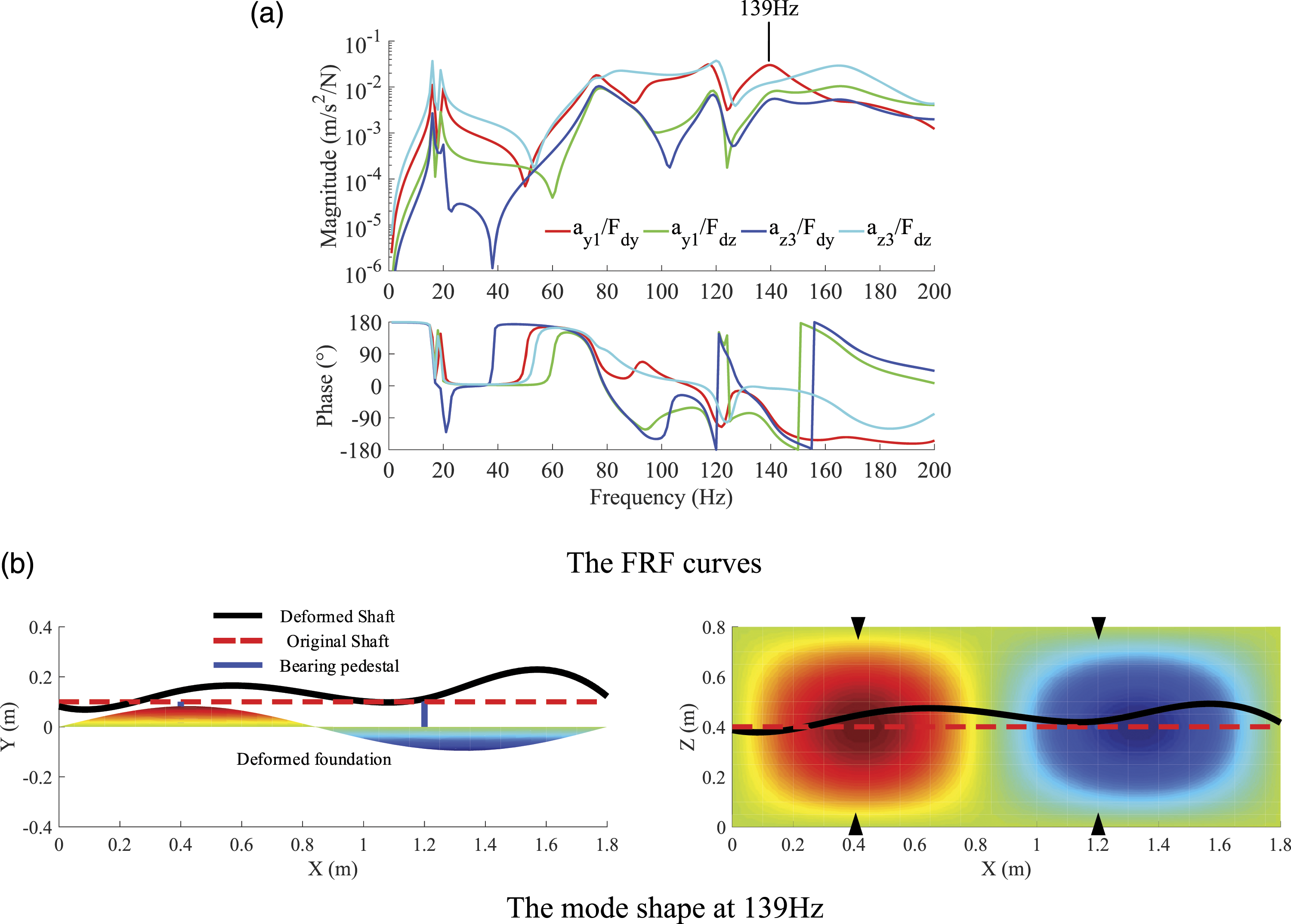
As can be seen, the FRF curves are of rich modes. The mode shape at 139 Hz is the shaft bending vertically and horizontally and the foundation bending vertically, which are coupled through the springs between the pedestals and foundation. Therefore, to realize full reduction of the foundation vibration, it might be necessary to suppress the vibration transmission from the shaft to the foundation in both vertical and horizontal directions.
4.2.1. The feasibility of the active control
The feasibility of the active control is first evaluated by the optimal control method given in Appendix 2. For the active vibration suppression, the vertical control indicates that the error responses
The shaft vibration transmits to the foundation via the pedestals, which are connected to the points The interfacial forces and moments between the pedestals and foundation.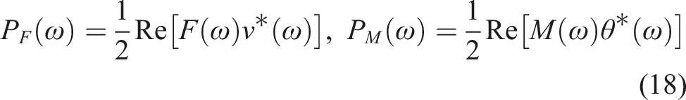
Suppose that the unit vertical and horizontal disturbance forces are applied at the disk. The power flow at Power flow generated by the interfacial forces and moments at 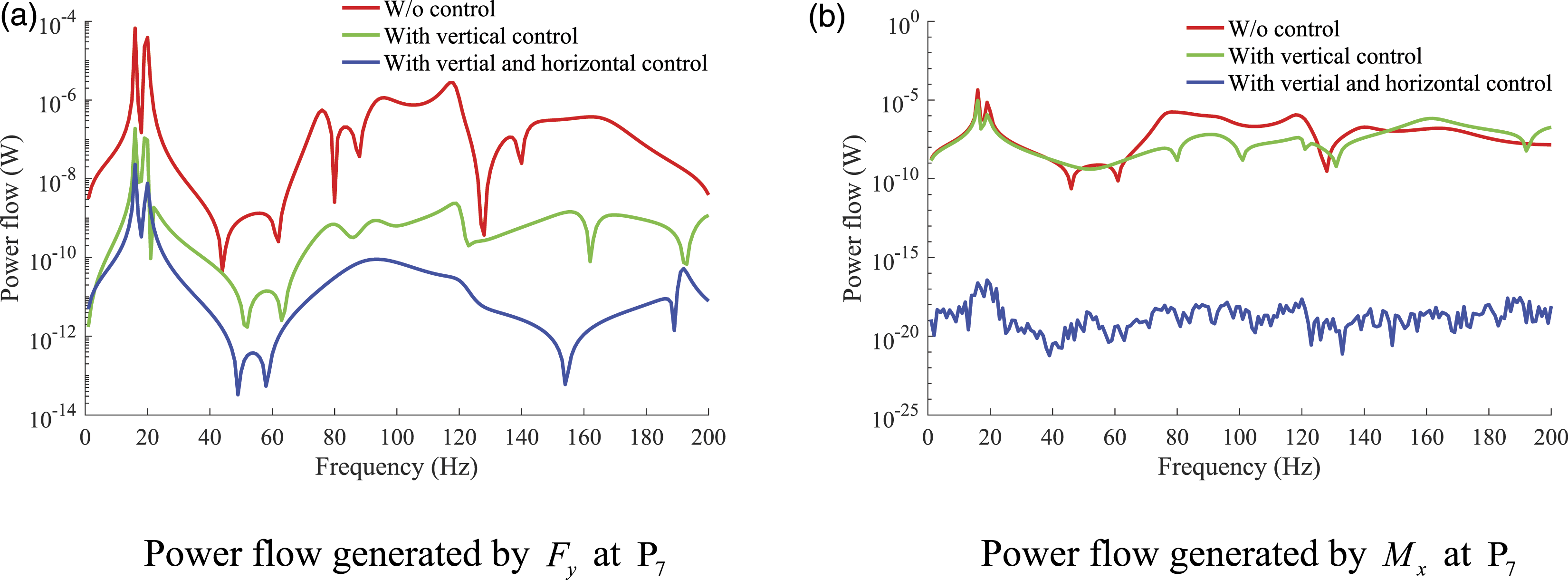
The Root Mean Square (RMS) values of the resultant of the vertical and horizontal shaft acceleration are shown in Figure 8(a). The shaft acceleration stays almost unchanged after control in 0–200 Hz, indicating that the electromagnetic actuators have little influence on the shaft vibration. The foundation acceleration is shown in Figure 8(b). After vertical control, the foundation vibration is suppressed mainly due to vertical power transmission attenuation. When the horizontal control is also applied, the foundation acceleration is further suppressed in the entire frequency range since the power flow generated by RMS values of the shaft and foundation acceleration (Ref=1×10⁻⁶m/s2) (a) The shaft acceleration (b) The foundation acceleration.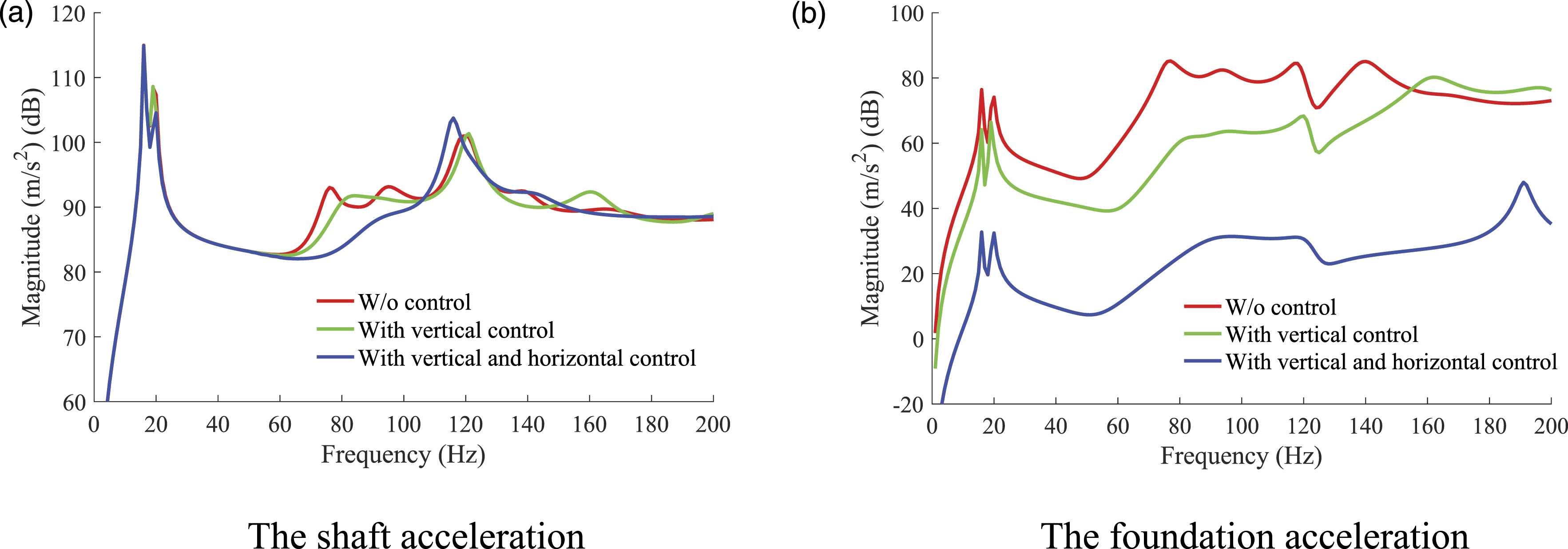
4.2.2. Multi-harmonic vibration suppression
The optimal control performance only theoretically represents the largest achievable attenuation. In this section, the performance is evaluated in a more practical way by the multi-harmonic vibration suppression method mentioned in Section 3. Suppose the vertical and horizontal disturbance forces are composed of five tones at 30 Hz, 60 Hz, 90 Hz, 120 Hz, 150 Hz, and white noise. These frequencies are chosen arbitrarily and located near or away from the resonant frequencies.
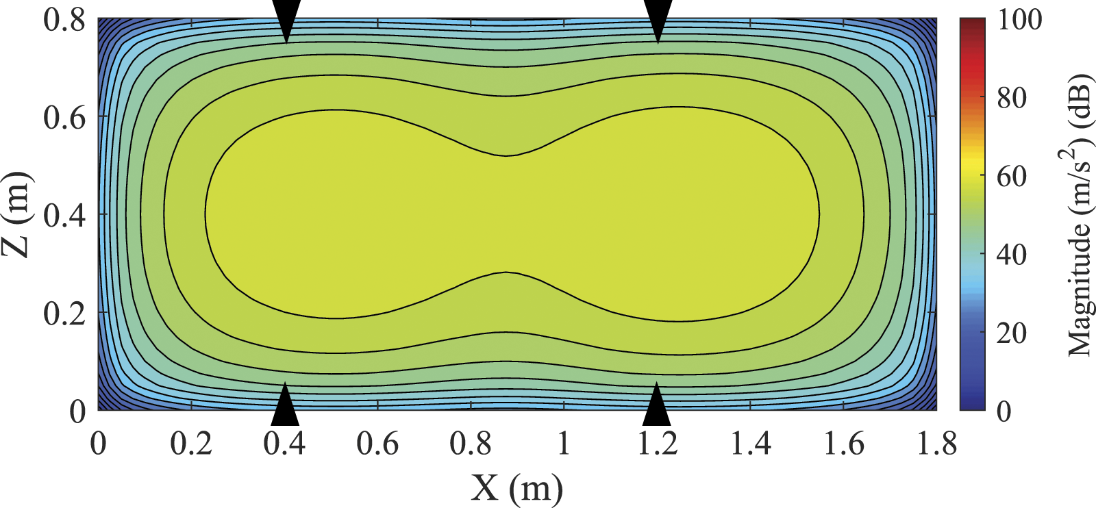
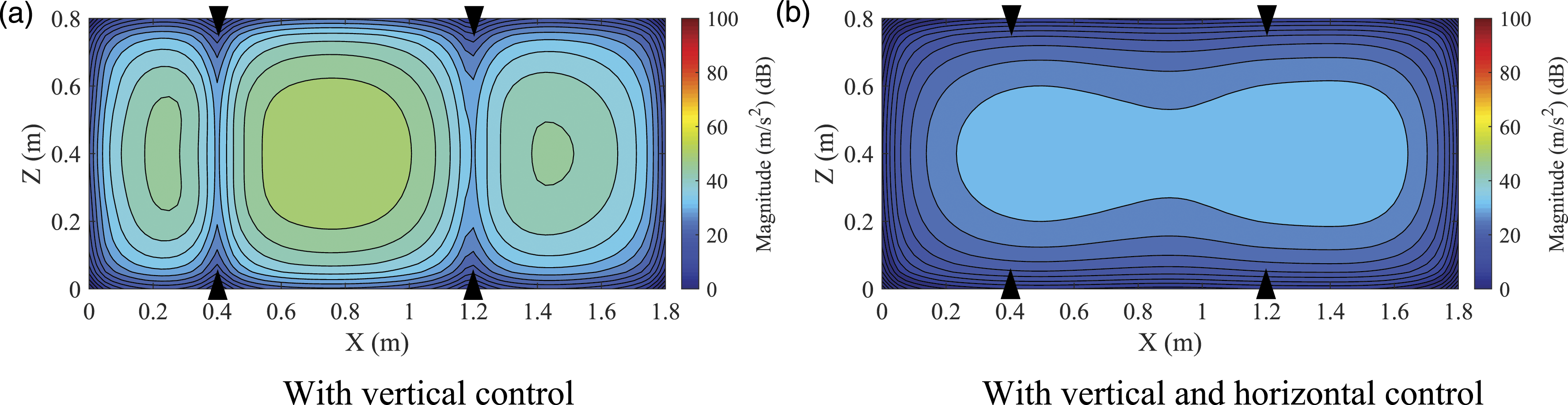
Attenuations at each frequency of the foundation acceleration and the RMS values are shown in Figure 9, where the foundation acceleration is attenuated at each frequency as well as the RMS values after vertical control. When the horizontal control is also applied, the foundation acceleration shows further reduction, which is consistent with the results of the optimal control. Contours of RMS values of the foundation acceleration before and after control are displayed in Figure 10 and Figure 11, respectively. It can be seen that the foundation vibration after vertical control is suppressed, especially near the bearing pedestals. With the addition of the horizontal control, the foundation acceleration in most areas is further attenuated compared to that with only vertical control, indicating that the non-contact electromagnetic actuators with the multi-harmonic vibration suppression method are able to suppress the vibration transmission. Attenuations of the foundation acceleration at each frequency and RMS values (Ref = 1 × 10⁻⁶m/s2). Contours of RMS values of foundation acceleration before control (0–200 Hz) (Ref = 1 × 10⁻⁶m/s2). Contours of RMS values of foundation acceleration after control (0–200 Hz) (Ref = 1 × 10⁻⁶m/s2) (a) With vertical control (b) With vertical and horizontal control.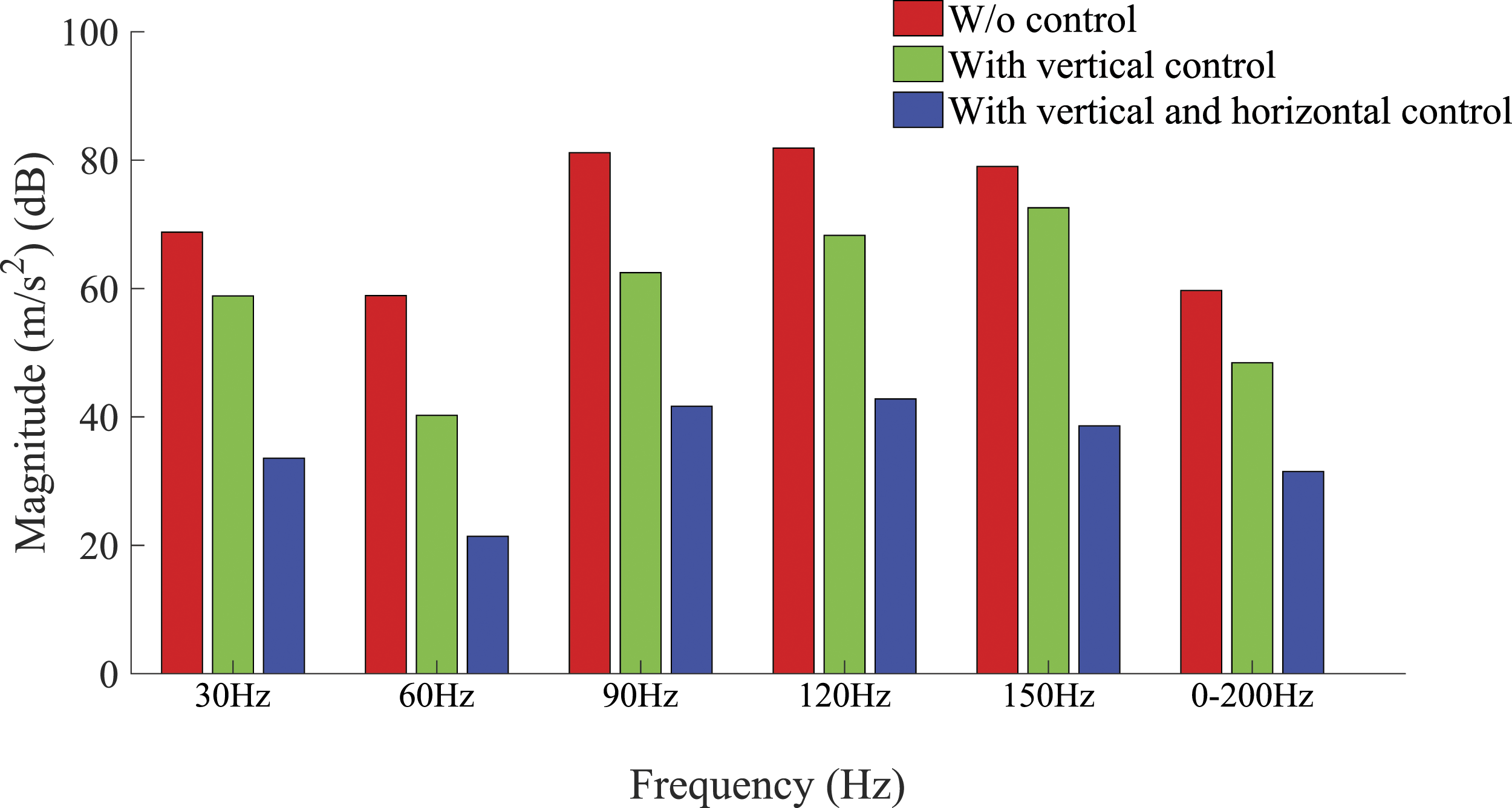
5. The proof-of-principle experiment
A proof-of-principle experimental system is built to verify the effectiveness of the vertical control by the non-contact electromagnetic actuators shown in Figure 12. The mechanical system mainly consists of a hull structure and two shafts supported by widely spaced bearings. The electromagnetic actuators are mounted at two paralleled intermediate bearings, where the mover and the magnetic pole are fixed to the bearing housing and the foundation, respectively. Two error accelerometers are mounted at the bearing pedestals, and five monitoring accelerometers are mounted on the hull structure. The eddy current displacement sensor is used to monitor the mover displacement. In the active control, the two shafts rotate at the speed of 1200 rpm and the bias currents are 15.8 A. The conditioned error signals are sent to the adaptive controller. The control currents generated by the controller are sent to the magnetic poles with the bias currents via the power amplifiers. Experimental system of the non-contact electromagnetic actuators.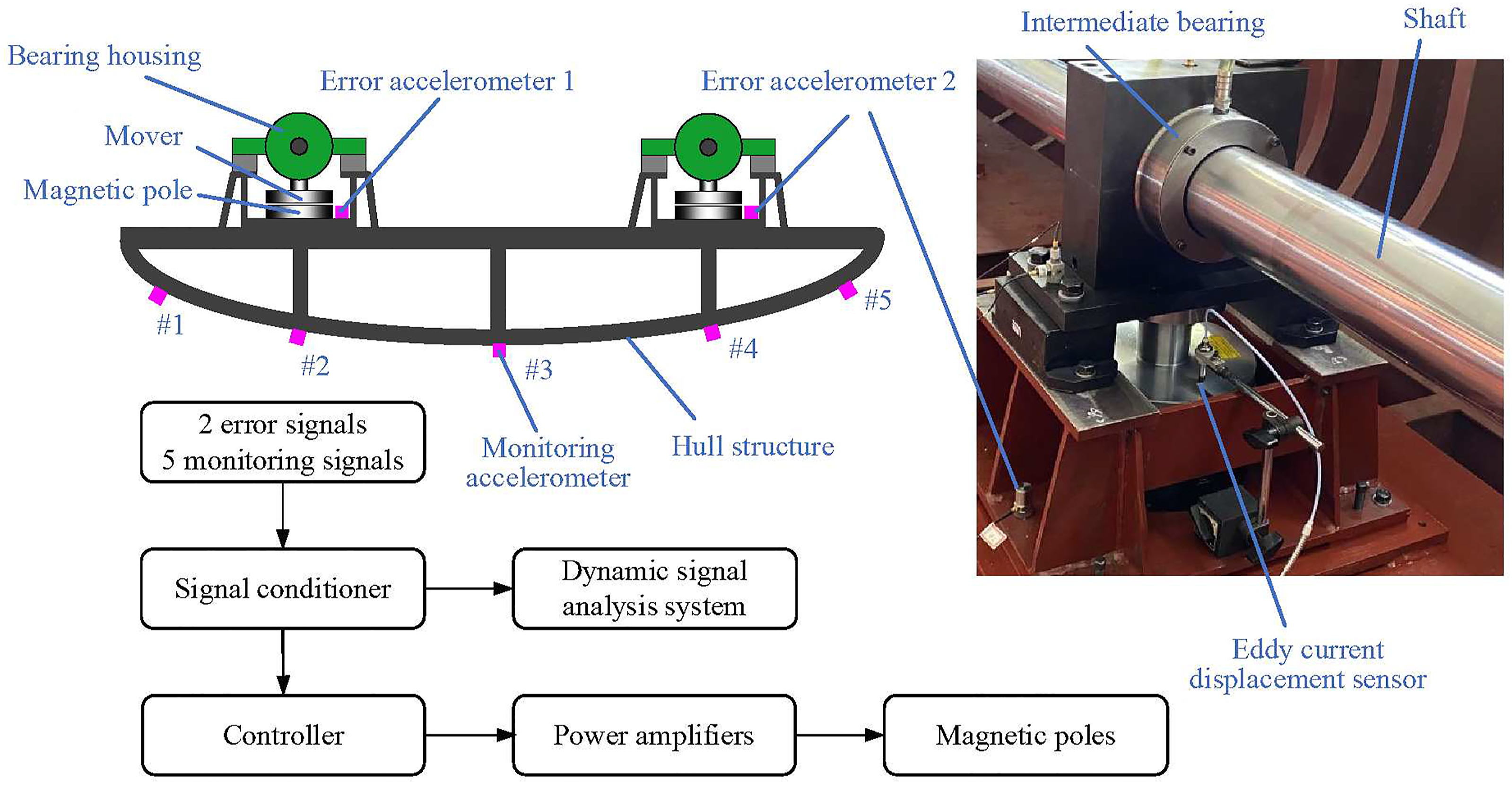
The PSDs (Power Spectral Densities) of the responses of the error accelerometers and the monitoring accelerometer #3 are shown in Figure 13. In Figure 13(a), the dominant peak of the error responses at the shaft frequency 20 Hz is attenuated by 16.4 dB and 17.3 dB, respectively, and the peaks corresponding to the multiples of the shaft frequency and the excitation frequency of the oil pump are suppressed by 15.7 dB and 8.3 dB. In Figure 13(b), the dominant peak at the frequency 20 Hz of the responses of the monitoring accelerometer #3 is attenuated by 15.9dB. Responses of the error accelerometers and monitoring accelerometer #3 (Ref = (1 × 10⁻⁶m/s2)2/Hz) (a) Responses of the error accelerometers (b) Responses of the monitoring accelerometer #3.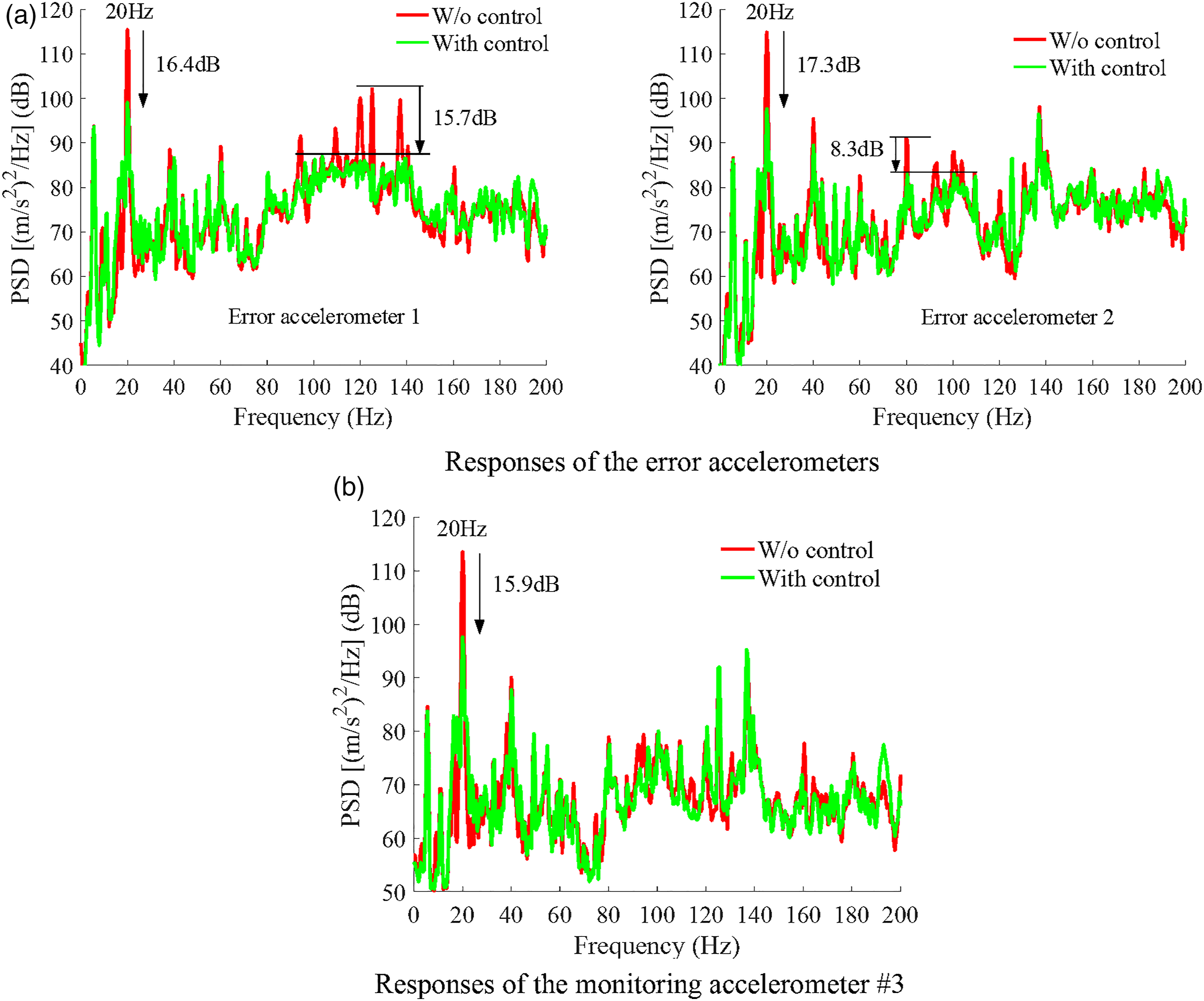
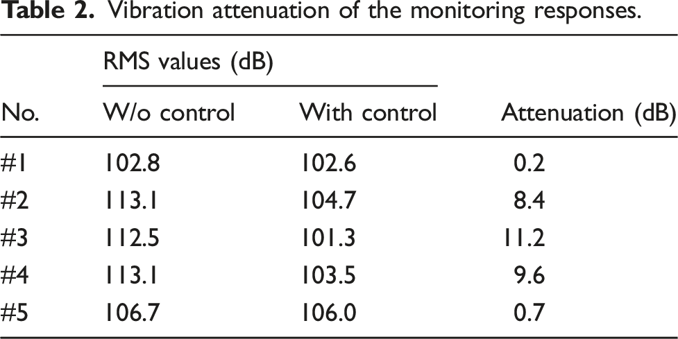
Vibration attenuation of the monitoring responses.
6. Conclusions
A new scenario based on non-contact electromagnetic actuators mounted at the bearing pedestals is proposed to suppress the vibration transmission from the shaft to the foundation. The numerical simulation is conducted based on the dynamic modelling of the shafting system and the results indicate that the displacement stiffnesses of the electromagnetic actuators have little influence on the vibration transmission. With vertical control by the electromagnetic actuators, the foundation vibration is suppressed at most frequencies mainly due to the suppression of the vertical power transmission. With the addition of the horizontal control, the foundation vibration is further suppressed especially owing to the reduction of the power transmitted by the interfacial moments. The multi-harmonic vibration suppression method is adopted and the harmonic vibration transmission through the bearing pedestals is effectively controlled. Experimental results have also shown that the vertical control by the non-contact electromagnetic actuators is effective in suppressing the vibration transmission from the shaft to the foundation and the foundation acceleration is significantly reduced.
Further experiments will focus on the validation of the effectiveness of the vertical and horizontal control by the non-contact electromagnetic actuators, the results of which will be compared to the those only with vertical control.
Footnotes
Declaration of Conflicting Interests
The author(s) declared no potential conflicts of interest with respect to the research, authorship, and/or publication of this article.
Funding
The author(s) disclosed receipt of the following financial support for the research, authorship, and/or publication of this article: This work was supported in part by the National Natural Science Foundation of China under Grant 52101363 and the China Postdoctoral Science Foundation under Grant 2020M681288.
Appendix 1
Appendix 2
According to equation (16), let
For the vertical control, the optimal control currents are assumed to suppress ay1 and ay2 to zero, which can be calculated by
For the vertical and horizontal control, suppose the optimal control currents can suppress the error responses to zero, which can be expressed as
Appendix 3
The formulas of the interfacial force/moment and velocity/angular velocity in equation (18) are given as