
Abstract
Ultralow-frequency band gaps are realized to suppress the ultralow-frequency flexural wave propagation in the beams with periodically attached quasi-zero-stiffness (QZS) resonators, which are designed by inserting quasi-zero-stiffness systems into the mass-in-mass structures. The band structure and the transfer matrix of the QZS locally resonant beam are derived by the transfer matrix method to quantify the wave attenuation performance of band gaps. Then, the effect of the stiffness ratio on the bandgap characteristic is studied. It is shown that, thanks to the introduction of the QZS system, the band gaps can be easily transferred to lower frequency or even ultralow frequency without weakening the static stiffness of the resonators. Finally, the flexural wave propagation in locally resonant beam consisting of multiple periodic arrays of QZS resonators is investigated. The result shows that differential design of the bandgap frequencies can be easily realized by adjusting the negative stiffness coefficient of the QZS resonators, so as to obtain broadband flexural wave suppression performance.
1. Introduction
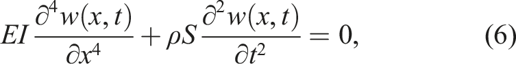
Beam-like structures are the fundamental elements of many practical structures, which are widely used in fields like aerospace, automotive, ship, and construction (Eken, 2019; Peng et al., 2020). Due to their wide application, the transverse vibration of beam structures has attracted extensive attention of researchers (Lee, 2000; Pai et al., 2014; Xie et al., 2020). At present, the control technology of medium and high-frequency vibration has been relatively mature. However, due to the limitations of actual engineering on quality and space, traditional methods are difficult to attenuate low frequency structural vibration without adding mass or weakening stiffness. So the low frequency vibration suppression design for such structures is still a challenging problem.
In recent years, the acoustic periodic structures (Goffaux and Vigneron, 2001; Huang and Sun, 2009; Kushwaha et al., 1993; Mead, 1996; Zhao et al., 2021) have attracted considerable attention because of the band gap characteristics not observed in nature. The wave in the band gaps can be attenuated significantly. It provides a new effective method for vibration and noise controlling technologies. The two main bandgap formation mechanisms are Bragg scattering (BS) and locally resonant (LR) mechanisms in previous and current researches. In the early stage, the band gaps of the acoustic periodic structures were studied based on BS mechanism (James et al., 1995; Sigalas and Economou, 1992). Since the generation of Bragg bandgap is caused by periodic scattering at the structural discontinuity, the wavelength corresponding to the bandgap frequency is generally proportional to the length of periodic cell (Wang et al., 2021a). Therefore, the size of periodic cells must be large enough to produce a low-frequency band gap to suppress the large wavelength flexural waves, which is usually difficult in engineering. In contrast, the frequency of the LR band gap is determined by the resonant frequency of the resonator and independent of the lattice constant.
The LR mechanism was first clearly proposed by Liu in 2000 (Liu et al., 2000). A LR structure with low frequency band gap is obtained by periodically arranging lead spheres wrapped by soft rubber in epoxy resin. Since LR mechanism has the application prospect of low-frequency vibration suppression, it has been widely studied since then (Bao et al., 2022; Li et al., 2019; Oudich et al., 2010; Peng and Pai, 2014; Sugino et al., 2017; Wang et al., 2004). Yu et al. (2006) derived the dispersion relation of a beam with periodically attached spring-masses. Huang and Sun (2009) proposed a mass-in-mass (MIM) resonator and deduced its equivalent mass. The results showed that the equivalent mass is negative in the band gap, which explained the attenuation mechanism of elastic wave in the band gap. At present, the research focus of LR is to design wider and lower band gaps. Xiao et al. (2012) widened the band gaps of the LR beam by attaching multiple arrays of damping resonators to the beam. Wang et al. (2016) obtained wide band gaps by strengthening the coupling among the resonators. Chen et al. (2017) designed multiple dissipative resonators to broaden the band gaps. Li et al. (2022) widened the band gaps by merging the bandgaps of stepped-frequency resonators. In addition, the combination of LR band gaps and Bragg band gaps is also one of the ways to broaden the band gaps (Bo et al., 2013; Wen et al., 2019). In addition to expanding the band gaps, the research on shifting downward the band gaps has attracted more and more attention (Assouar et al., 2014; Bao et al., 2021; Li and Li, 2017; Wu et al., 2019). By introducing the inertial amplified mechanism to LR structure, Yilmaz et al. (2007) obtained low-frequency band gaps without increasing the mass or reducing the stiffness of the resonators. Wang et al. (2021b) derived the bandgap structure of the beam with inertial amplified resonators and verified its low-frequency band gap characteristics. With the development of industry, higher requirements are put forward for the control of ultralow-frequency vibration. Therefore, it is necessary to design a resonator with ultralow-frequency band gaps.
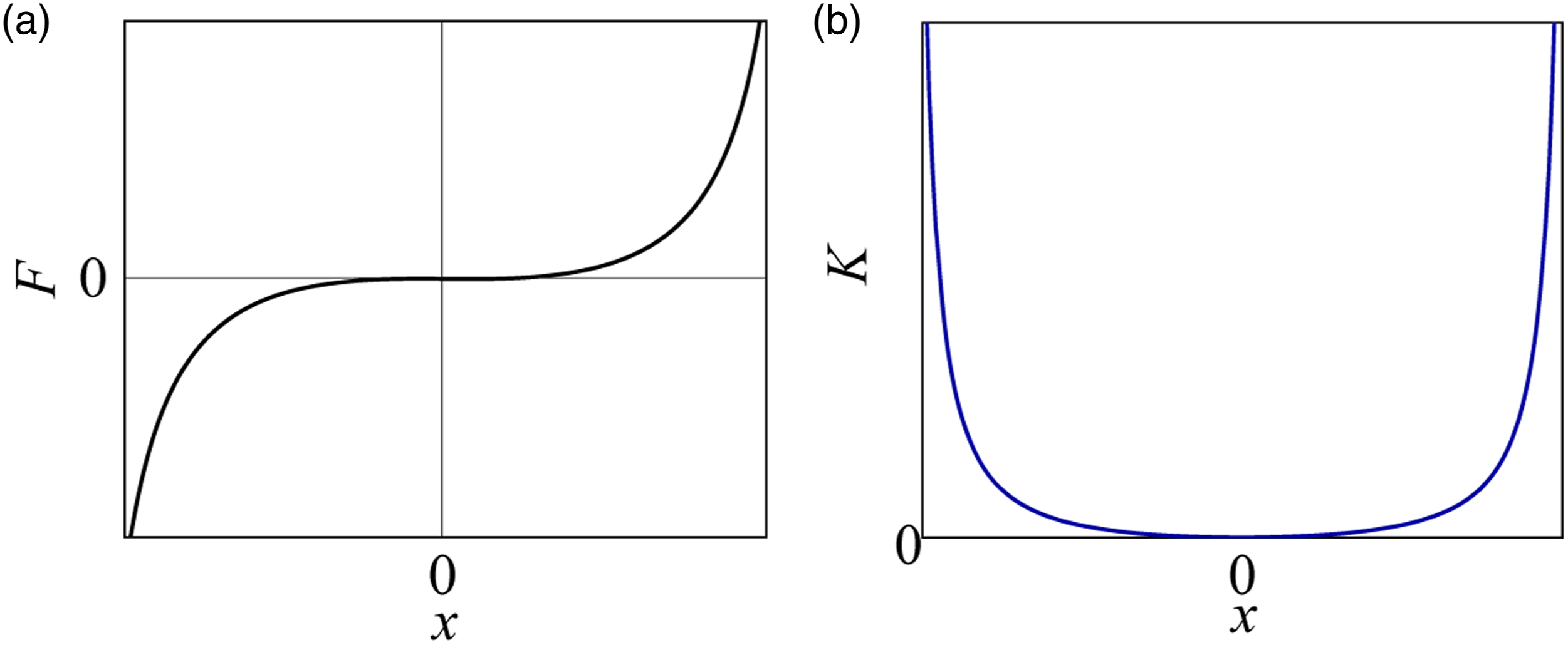
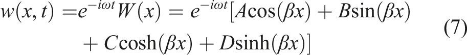
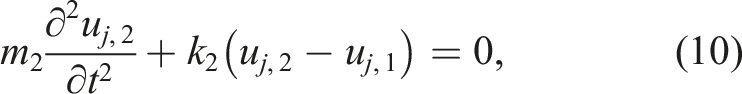
Reducing the dynamic stiffness of the resonator is one of the effective methods to obtain ultralow-frequency band gap. However, low dynamic stiffness means low static stiffness for the conventional resonators, which will seriously weaken the rigidity of the structure. Therefore, obtaining wide ultralow-frequency band gaps is still a very challenging work in practice. In order to solve the contradiction between ultralow-frequency band gap and ultra-weak stability, the author draws lessons from ultralow-frequency vibration isolation measures. An ultralow-frequency vibration isolation system is shown in Figure 1, namely, quasi-zero-stiffness (QZS) system (Carrella et al., 2007). The QZS system combines two symmetric springs in the horizontal direction and a load supporting spring in the vertical direction, where the horizontal springs are pre-stressed to provide negative stiffness. The static stiffness of the vibration isolation system is determined by the vertical spring. The force-displacement curve and the equivalent dynamic stiffness-displacement curve of the QZS structure in operation are illustrated in Figure 2(a) and Figure 2(b), respectively. As can be seen from the figure, the equivalent stiffness of the QZS structure is as low as zero at the equilibrium position. The structure model of the QZS isolator. (a) the force-displacement curve and (b) the equivalent stiffness-displacement curve of the QZS system.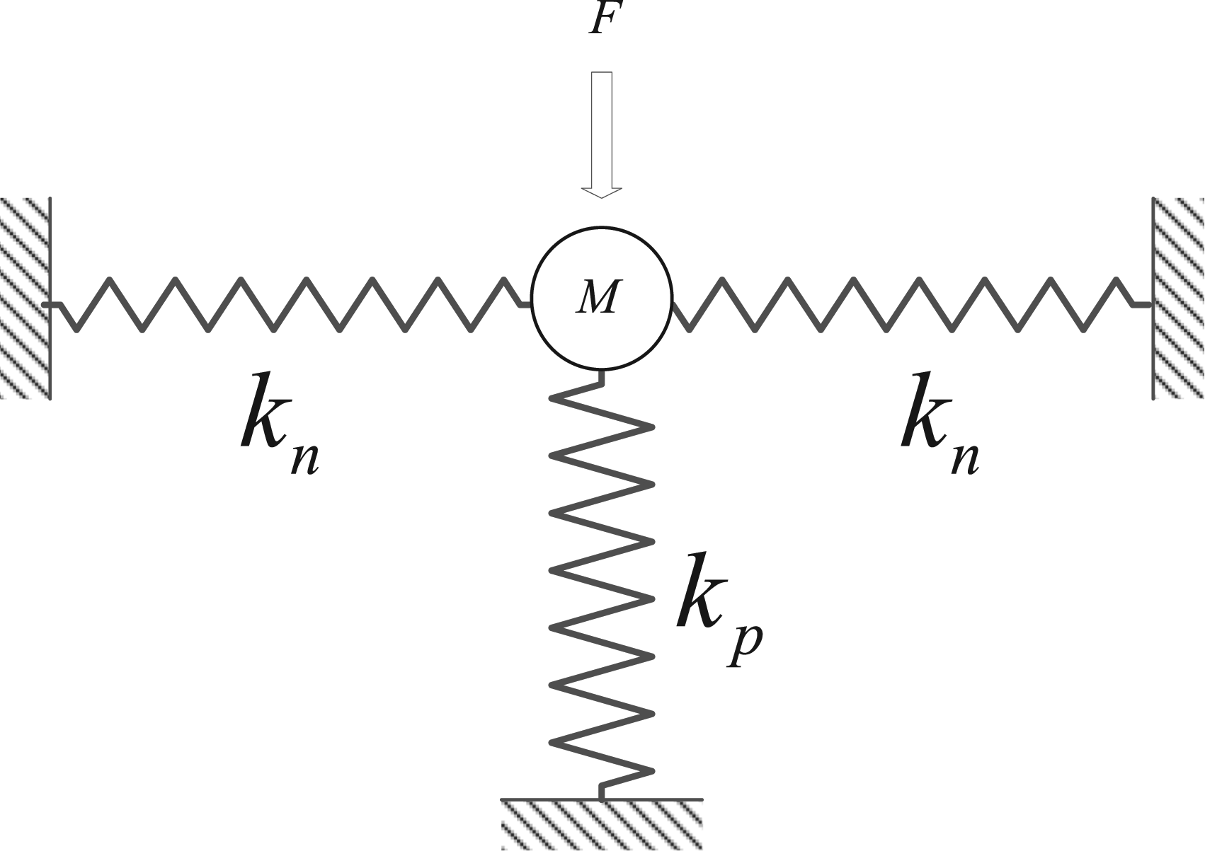
At present, the QZS systems are mainly used in the field of ultralow-frequency vibration isolation (Zhang and Cao, 2022). Le and Ahn (2011) designed a vibration isolation system in low frequency excitation region for vehicle seat by using QZS system and proved experimentally that the system can effectively isolate vibration as low as 0.1 Hz. Lan et al. (2014) proposed a compact QZS isolator capable of a wide range of loads. Yan et al. (2020) designed a large stroke QZS vibration isolator to enhance its practicability. However, there are few studies on the design and band gap theory of the LR structure based on QZS system to attenuate ultralow-frequency flexural waves at present. Cai et al. (2020) proposed a one-dimensional QZS metamaterial to acquire low-frequency band gaps and numerically verified its ability to suppress low-frequency longitudinal waves. The lack of existing structures and theories seriously restricts the application of QZS LR structure in practice.
Inspired by the ultralow-frequency vibration isolation system, ultralow-frequency band gaps are obtained by introducing the QZS system into the design of LR beam to attenuate the flexural wave. The work is organized as follows. Theoretical derivation is presented in detail to investigate the dispersion relation of the Euler–Bernoulli beam with QZS LR structures in Section Ⅱ. The influence of parameters on the band gaps is studied in Section Ⅲ to guide the design of the QZS LR in practical applications. Finally, conclusions are drawn in Section Ⅳ.
2. Theory and modeling
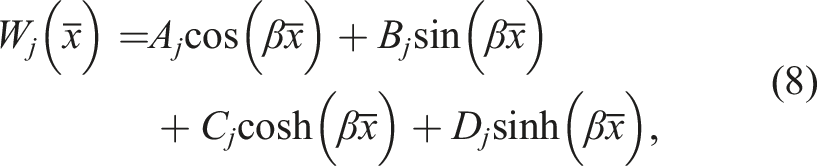
The physical modal of an Euler–Bernoulli beam with attached QZS resonators along x direction is illustrated in Figure 3. For clarity, only two unit cells of the LR beam are fully depicted in the figure. The resonators are distributed periodically on the beam with a period Schematic diagram of an infinite LR beam.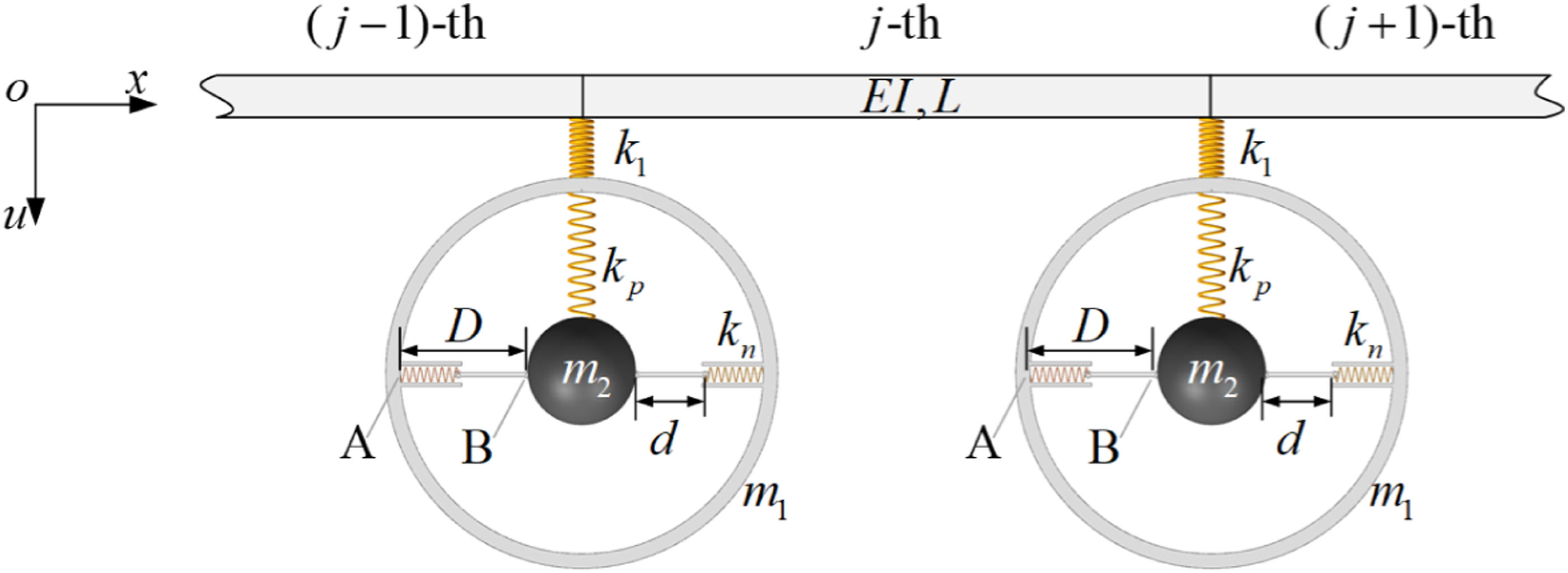
According to the geometric relationship of the QZS system, when the positive extension of the positive stiffness The normalized equivalent stiffness respects to 
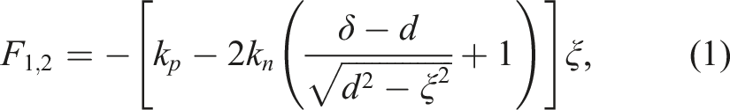
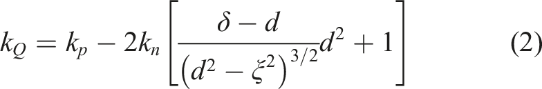
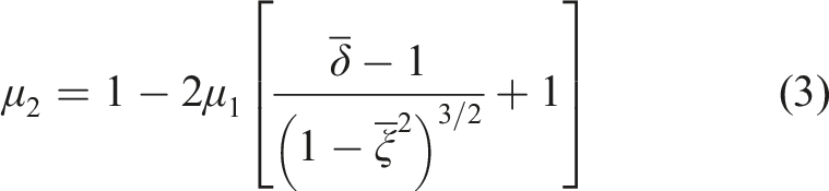
The purpose of this study is to realize ultralow-frequency band gaps by introducing QZS system, so the value of the parameter
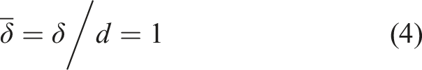
Substituting the equation (4) into equation (2) yields

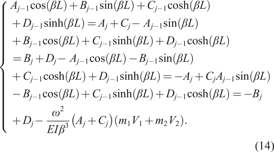
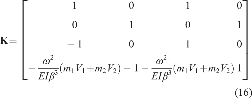
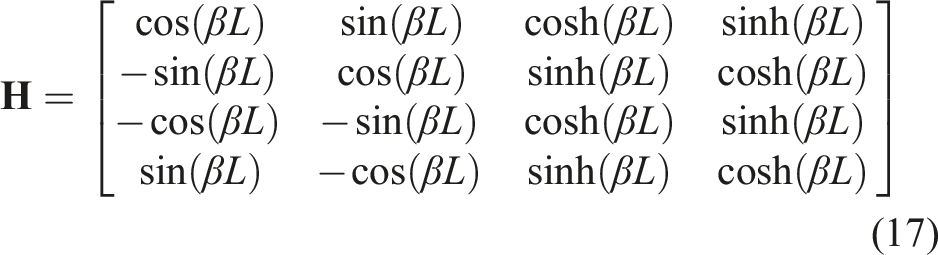
Transform equation (14) into matrix form gives


3. Numerical results and discussions
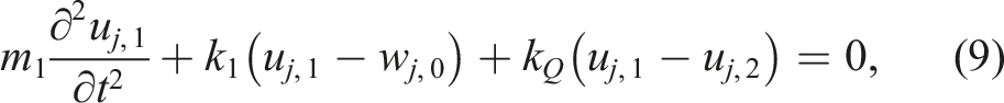
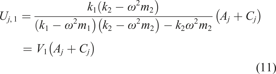
In order to predict the positions of band gaps in advance to guide the design of the resonators, the resonant frequencies of the two degree-of-freedom resonator are derived here. Transform Equation (9) and Equation (10) into matrix form gives
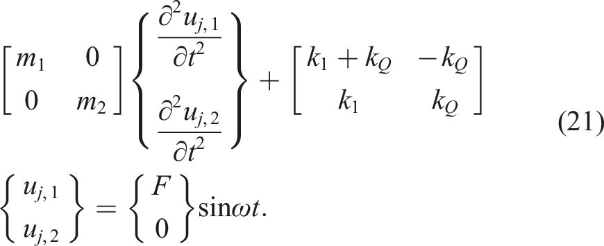
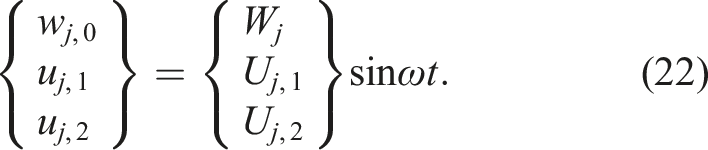
Substituting equation (22) into equation (21) gives
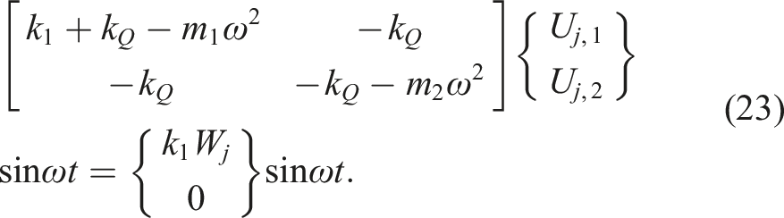
Then, equation (23) can be written as
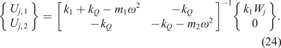
Based on equation (24), we can obtain the following equations:
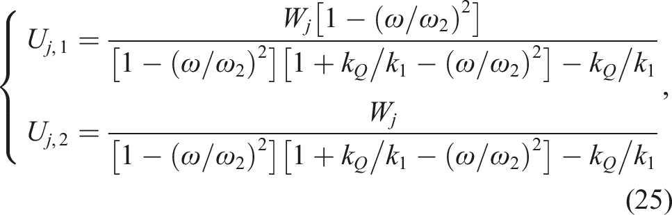
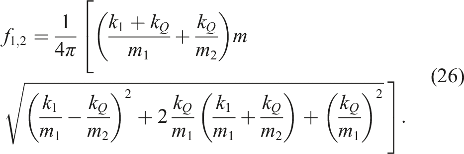
According to equation (26), the resonant frequencies of the resonators are 39.9 Hz and 504.9 Hz. The band structures of the QZS LR beam shown in Figure 3 are presented in Figure 5. It can be seen that there are two band gaps just at the resonant frequencies of resonators. The band structures of the QZS LR beam (where the gray areas represent the band gaps).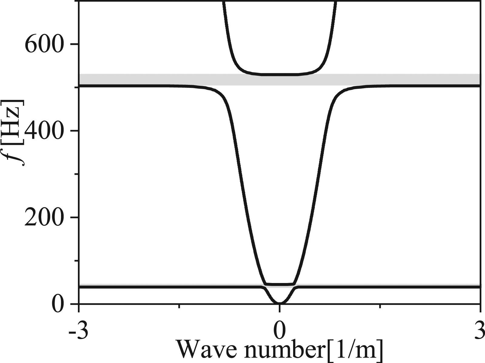
The imaginary part of the transfer matrix is shown in Figure 6(a). And the FRF of a finite LR beam with 9 unit cells calculated by FEM is shown in Figure 6(b). Where the imaginary part of the transfer matrix reflects the position of the band gap and the attenuation ability of the flexural wave at the same time. Correspondingly, flexural waves within the band gaps are obviously attenuated. And in the band gaps, the curve of the imaginary port of the transfer matrix has the same trend as the attenuation curve. It should be noted that the transmission valley at 109 Hz in the Figure 6(b) is caused by the vibration observation point at the bending wave node, which is independent of the band gaps. The good agreement with the FEM results verifies the accuracy of the band gap theory. (a) The imaginary part of the transfer matrix, (b) the FRF of the QZS LR beam.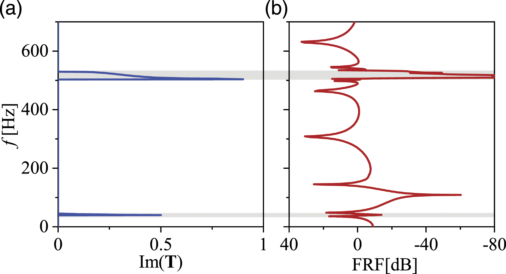
Further, in order to verify the advantages of the LR structure proposed in this study, the FRF of the beam with QZS resonators and the beam with MIM resonators are compared in Figure 7(b). The corresponding parameters of QZS resonators and MIM resonators are set the same to make the results comparable. In addition, the FRFs of the bare beam and the beam with equal mass addition are also shown in the figure as a comparison. It can be seen that the QZS LR beam can generate two band gaps which are 39 Hz–44 Hz and 505 Hz–535 Hz, respectively. In particular, the first band gap greatly reduces the first modal vibration of the beam by 20dB. In contrast, the two band gaps of the LR beam attached with MIM resonators are 218 Hz–245 Hz and 570 Hz–603 Hz. In other words, the band gaps of the LR beam are moved significantly to lower frequencies thanks to the introduction of QZS systems. Therefore, the effectiveness of the QZS LR proposed in this study is demonstrated. (a) Schematic diagram of the MIM LR beam. (b) the frequency response functions of the different structures.
It can be seen from equation (5) that the equivalent stiffness of QZS system is determined by the difference between the stiffness Dependence of the band-gap boundaries on the stiffness ratio 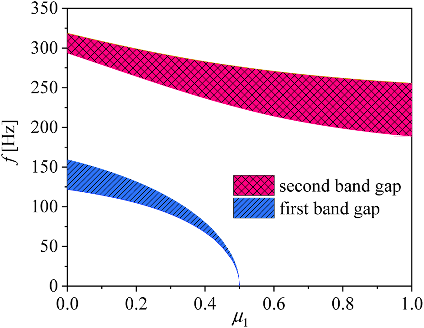
It can be seen from Figure 8, since the stiffness ration
As can be seen from Figure 8, the width of first band gap narrows with the increase of The effect of the parameter 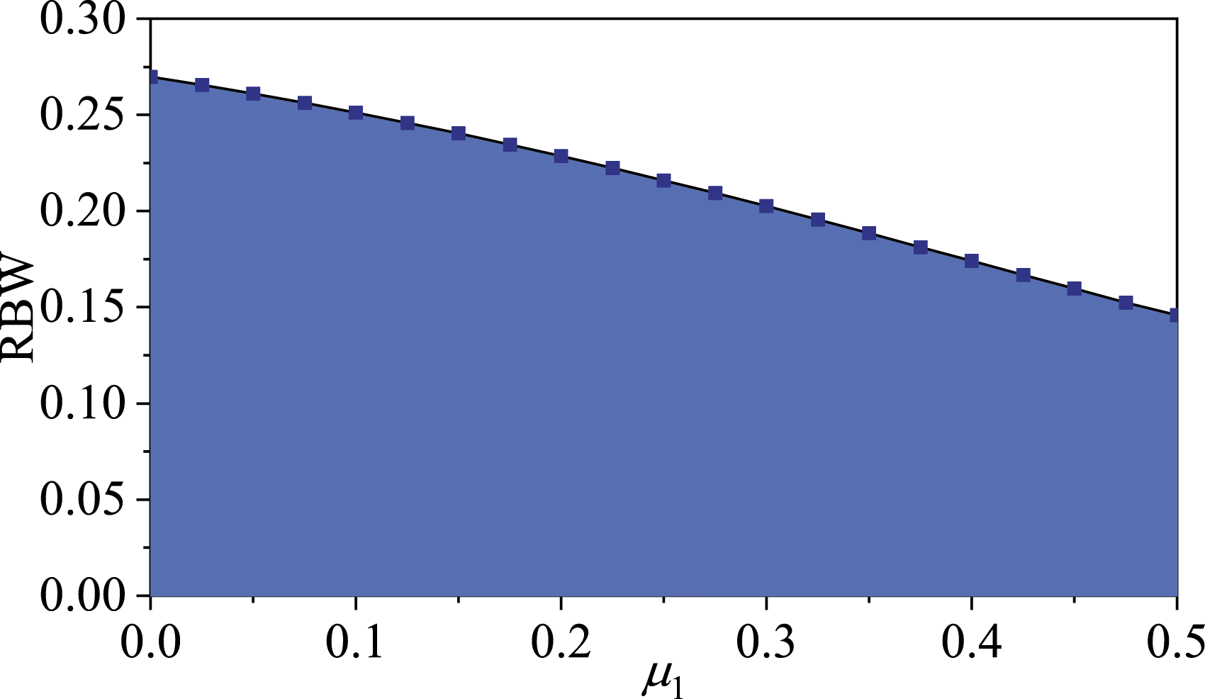
In addition to reducing the band gap frequency, broadening the band gaps is also a research focus of the LR structure, which is also the aim of this study. Theoretically, the band gaps can be broadened by increasing the mass ratio of the resonator to the base beam. However, the mass ratio is usually strictly limited in practice. The strategy adopted in this study is to obtain multiple band gaps through the differential design of stiffness Schematic diagram of an infinite LR beam with multiple periodic arrays of attached QZS resonators.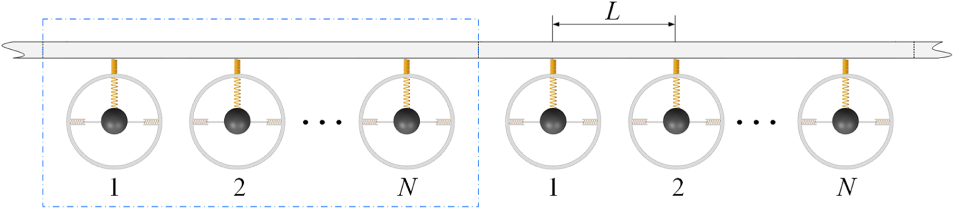
The only difference among resonators with different numbers is that the stiffness Effects of damping on the FRF of the beam with 3 arrays of QZS resonators.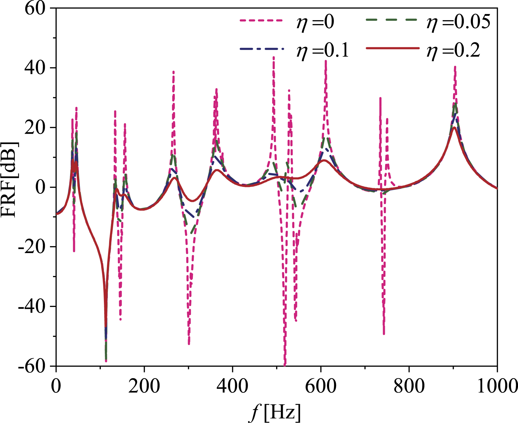
It is evident in Figure 11 that there are six band gaps of the LR beam with 3 arrays of QZS resonators. The first three band gaps are the first band gaps of different array resonators and the three band gaps near 600 Hz are the second band gaps. It can be seen that the undamped resonators can produce considerable attenuation of flexural wave in the band gaps, but the high vibration response at the edges of the band gaps is not expected in vibration control. Increasing the damping of the resonators has an obvious smoothing effect on the transmission peaks and dips. Although the attenuation ability of band gaps to flexural wave is deactivated by the damping in a different extent, the vibration peaks at the edges of the band gaps are significantly reduced, which is more beneficial in practical engineering.
In order to further demonstrate the vibration suppression ability of the multi-array periodic model, the FRF of the LR beam with 3 arrays of QZS resonators is compared with that of the LR beam with only a single array of QZS resonators, as shown in Figure 12. In the figure, the Model-1 represents the beam with equal mass, the Model-2 represents the LR beam with equal mass a single array of QZS resonators and the Model-3 is the LR beam with three arrays of QZS resonators. And the Model-2 and Model-3 have the same total resonator masses and the loss factor of all resonators are set to 0.2. The negative stiffness coefficients of all resonators in the single array model are set as Comparison of FRFs with different resonator arrays attached to the beam.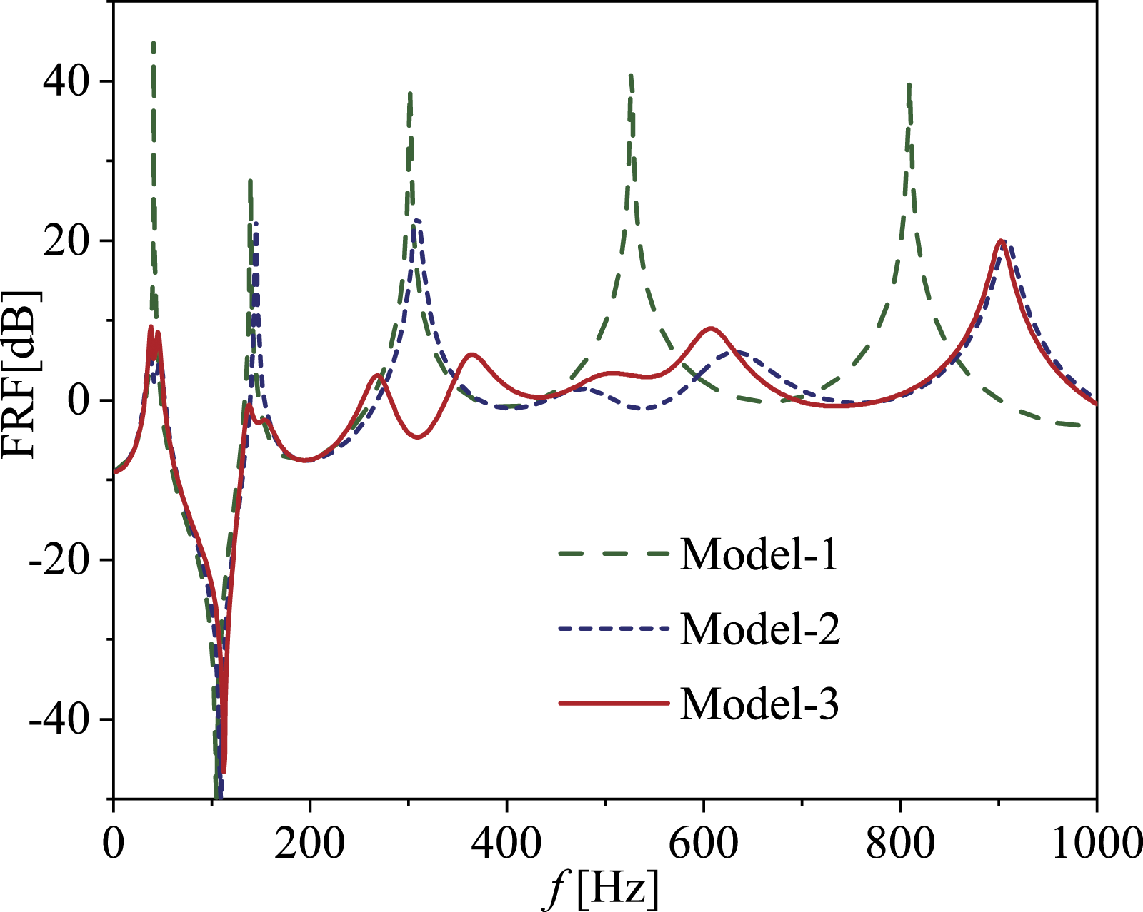
Figure 13 shows the displacement responses of different models at the frequencies within the above two bandgaps. It can be seen that the displacement of Model-2 is not weakened relative to Model-1. As a contrast, the bending vibration of Model-3 is significantly attenuated. Therefore, flexural wave below 700 Hz in the beam with three arrays of QZS resonators are effectively suppressed. In other words, thanks to the introduction of QZS system, the band gaps of LR beam can be easily adjusted to realize the differential design of band gap frequencies. So as to achieve the purpose of broadband vibration suppression. The displacement responses of different models at the frequencies within bandgaps. (a) 145 Hz (b) 301 Hz.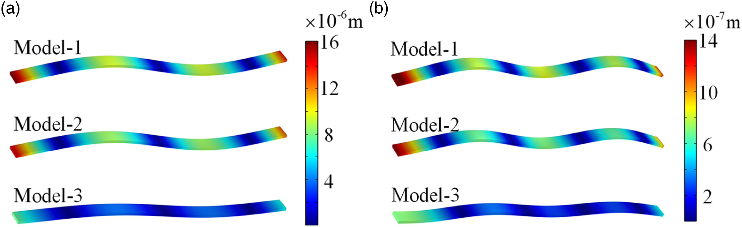
4. Conclusions
The modeling and analysis of a LR beam attached with quasi-zero-stiffness (QZS) resonators is investigated in this study. The band structure and transfer matrix of the LR beam are derived by the transfer matrix method, where the imaginary part of the transfer matrix can not only show the position of the band gaps, but also reflect the attenuation ability of LR beam to the flexural wave. Then, a parametric study is performed to investigate the effects of stiffness on the band gaps of QZS LR beam. Thanks to the introduction of the QZS system, both the first band gap and second band gap can be shifted to lower frequencies by adjusting the negative stiffness coefficient. In particular, the first band gap can be flexibly transferred to ultralow-frequency without weakening the static stiffnesses of the resonators. Therefore, the QZS LR can be used to suppress the propagation of ultralow-frequency flexural wave. Finally, the flexural wave propagation in LR beam consisting of multiple periodic arrays of QZS resonators is investigated. The result shows that differential designs of the bandgap frequencies can be easily realized by adjusting the negative stiffness coefficients of the QZS resonators, so as to obtain broadband flexural wave suppression performance. The research verifies that the QZS LR proposed in this study has the application prospect of suppressing ultralow-frequency and broadband flexural wave in the beam.
Footnotes
Declaration of Conflicting Interests
The author(s) declared no potential conflicts of interest with respect to the research, authorship and/or publication of this article.
Funding
The authors disclosed receipt of the following financial support for the research, authorship, and/or publication of this article: This work was supported by the Natural Science Foundation of Shaanxi Province, China (Nos.2021JLM-39) and the Natural Science Foundation of Ningbo City, China (Nos.2021J057).