
Abstract
Shaking tables are widely used across numerous engineering research and industrial sectors, including mechanical (e.g. automotive and aerospace testing), electrical (e.g. instrumentation testing) and civil (e.g. structural and geotechnical testing) engineering. It is commonly required to replicate the shake table motions accurately and precisely. Iterative learning control algorithms can be used to complement traditional proportional–integral–differential feedback control algorithms to optimize drive signals using a test payload prior to the real experiment. Historically, the design of these test payloads has focused on matching the mass of the actual payload and neglected its dynamic response. In this study, experimental results from shake table tests using multiple geotechnical containers with dry and saturated beds that exhibit a range of stiffnesses and material damping when shaken are presented. Errors between the demanded and achieved motions are explored and compared to the changing secant stiffness abstracted from the dynamic shear stress–strain loops of the payload. A clear trend emerges that demonstrates increased errors as the payload stiffness deviates from the constant stiffness test payload originally used with the open loop iterative learning control, and further the errors are not necessarily bounded by test payloads significantly softer or stiffer than the actual specimen. The findings support that in cases where repeatable, accurate and precise shake table motions are required for payloads that exhibit a complex material response that is not readily modelled mathematically, it may be necessary to reproduce the specimen’s overall dynamic response during the iterative learning control process.
Keywords
1. Introduction
Shaking tables are widely used across numerous engineering research and industrial sectors; including mechanical (e.g. automotive and aerospace testing), electrical (e.g. instrumentation testing) and civil (e.g. structural and geotechnical testing) engineering. A common theme across these applications is the requirement for accurate and precise production and replication of the shake table motions. Shaking tables are typically actuated using mechanical, servo-hydraulic or electro-dynamic systems that can utilize open or closed loop control strategies. Typically, closed loop strategies have primarily utilized displacement feedback due to pure velocity or acceleration feedback systems being insensitive to constant displacements and/or velocity drifts. Closed loop displacement control can be achieved through proportional–integral–differential (PID) feedback algorithms, and manual tuning can lead to reasonable performance over limited frequency ranges. However, for higher or larger range shaking frequencies, or applications with strict acceleration demands, additional control strategies are required (Dyke et al., 1995; Nakata, 2010; Venanzi et al., 2017).
To this end, iterative learning control (ILC) strategies can be incorporated to automatically calibrate the shaker drive signal based on measurements of the achieved table motion (Figure 1). Whilst the PID feedback controls the instantaneous table motion, ILC strategies commonly utilize velocity or acceleration time histories across a longer time window with the error between the demanded and achieved motion used to update shaking in the subsequent window. Much of the research into ILCs has been inspired by Arimoto et al. (1984). ILC strategies can be used for open or closed loop control and are distinct from adaptive control as the input signal is modified but the controller is not. Bristow et al. (2006) describe ILC as being similar to repetitive control, with the main distinction in terms of initial conditions, for example, in repetitive control, the systems final condition is the beginning state for the next iteration versus ILC that is typically applied to systems beginning and ending at a steady state. An important distinction to feedback and feedforward design is also made – by targeting open loop control per iteration, ILC does not attempt to correct random errors, but can correct systematic errors that arise from repeating factors such as friction in a more stable manner without risking errors due to tracking lag. Plummer (2007) presents a comprehensive review of control techniques used for structural testing, summarizing that at present open loop iterative control strategies that measure and model the system in the frequency domain across each iteration are most prevalent in practice. Recently, Vemula et al. (2021) presented a theoretical and experimental study to demonstrate the performance of ILC systems in reducing the error between demanded and achieved signals. Illustration of simplified iterative learning control loop diagram.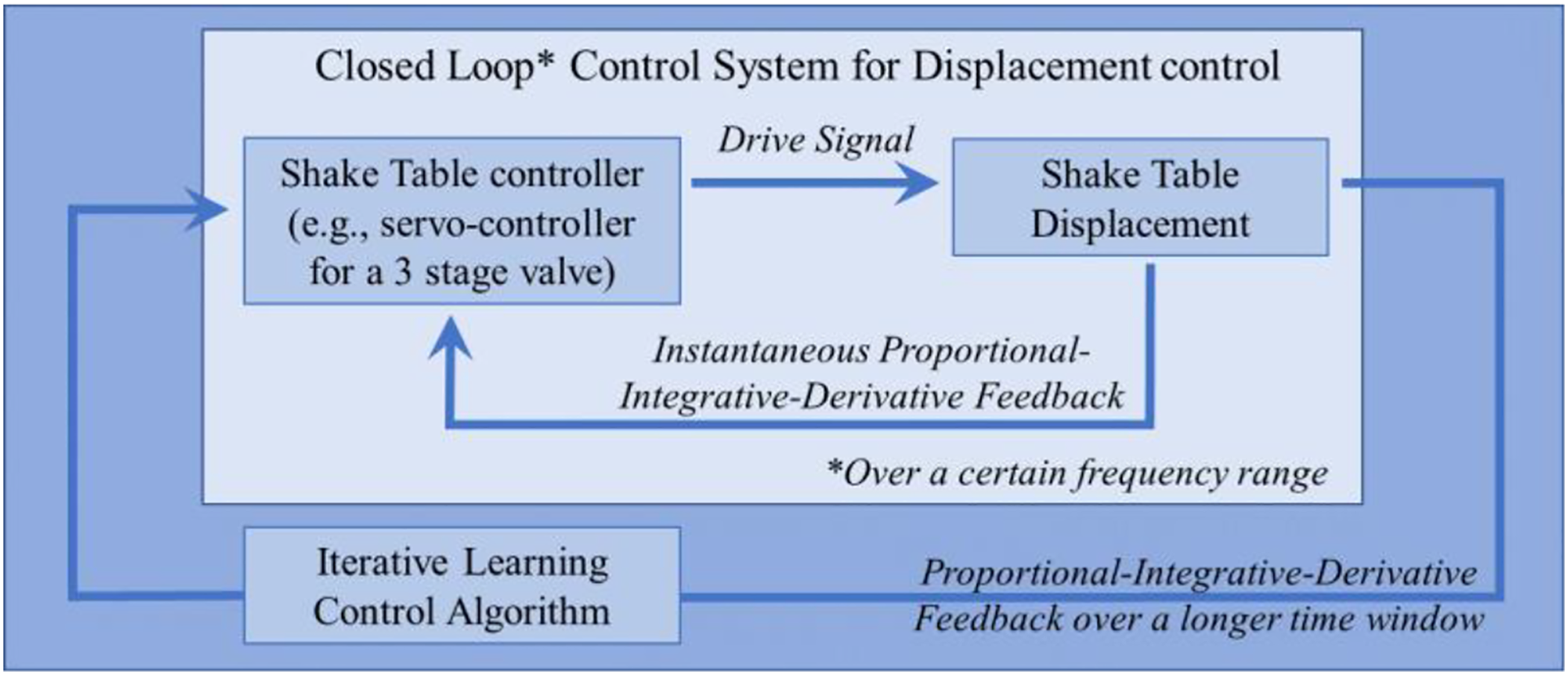
Minimization of measured errors through updating the drive signal can be an automated process. Combined control strategies (e.g. PID with an ILC outer loop) can address the respective weaknesses of the individual approaches, for example, non-linearities of the system response, difficulties with manual tuning of the shake table, frictional forces, sensitivity to drifts in the motion or its derivatives, phase lags between the current and measured table motion or interaction between the shake table and payload (Ghalibafian et al., 2004; Stoten and Shimizu, 2007; Gang et al., 2013; Dai et al., 2022).
Using the combined and automated control strategy, drive signals can be efficiently calibrated prior to shake table experiments using a test payload before using the calibrated drive signals with the actual payload. Approximate matching of the test and actual payload mass is important during the motion calibration (Phillips et al., 2014). However, whilst it is often acknowledged that the payload dynamics can influence the calibrated motions achieved, matching of stiffnesses between the test and actual payload is less commonly discussed (Yachun et al., 2018; Wang et al., 2022). Further, in many applications, whilst the payload mass is fixed, the payload can experience significant changes of stiffness due to the applied motion. The potential for this to introduce errors between the calibrated motion for fixed stiffness and the achieved test motions has not been well explored and is the subject of the current study.
Geotechnical earthquake research commonly utilizes shake table testing at various scales to understand and measure the behaviour of soil under dynamic or seismic loading. This can provide insight for civil engineering applications including earth or water retaining systems, soil structure interaction problems and the liquefaction phenomenon. The soil models can be tested in ‘1 g’ conditions and constructed at small or medium scales (e.g. Iai, 1989; Jahed Orang et al., 2021; Nakashima et al., 2018; Yamazoe et al., 2018) or tested in a geotechnical centrifuge at ‘N × g’ where the stresses within reduced scale models are increased by the centrifugal acceleration to accurately capture the stress–strain behaviour of the full scale case at homologous points in the model (Garnier et al., 2007; Schofield, 1980). Such testing has revealed the significant change to soil stiffness due to densification and locked-in stresses of the soil skeleton (e.g. Craig and Knappett, 2012; Madabhushi and Haigh, 2019) and/or the generation of excess pore pressures, reduction of effective stress and thus stiffness in saturated soils subject to cyclic loading (Kramer, 1996; Madabhushi and Haigh, 2012; Kutter et al., 2020). Similarly, precise fatigue testing of structural members or electrical components in the seismic structural design, automotive and aerospace sectors has revealed progressive changes of payload stiffness (e.g. Blondet and Esparza (1988) or Kersch and Woschke (2020)). Plummer (2007) discusses control strategies for structural testing with non-linear, high order dynamic responses and the preferred use of ‘outer loop’ (e.g. ILC in the frequency domain) methods in the automotive industry versus adaptive control/inverse physical models. The latter approaches have generally been restricted to the control of simpler systems such as individual hydraulic cylinders (e.g. Jaiswal et al., 2021; Kim et al., 2021). In all cases the impact of the dummy and real payload dynamics on the performance of outer loop ILC strategies requires further research in terms of the discrepancies between the demanded and achieved input motions within single or multiple test experimental programs. For example, the validation of predictions of single test responses or for accurate cross comparisons between experiments where payloads were intended to be subjected to the same input motion that differed in practice. Further, there is a need for a straightforward and more general interpretation of the experimental results, and specifically the payloads dynamic response, to inform the control strategy’s performance and influence of the system dynamics.
2. Experimental design
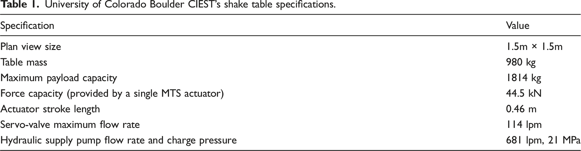
University of Colorado Boulder CIEST’s shake table specifications.
The instantaneous shake table position was controlled by a closed loop PID system based on displacement feedback through an MTS FlexTest 60 controller. The table was previously calibrated and verified to produce consistent and repeatable motions for a given drive signal and similar initial payload characteristics. An ILC loop utilizing acceleration feedback through a Vibration Research™ VR9500 controller and VibrationVIEW software was added, for example, Figure 1. This controller iteratively corrects the frequency and phase distortions inherent in the PID servo-controller to better match the demanded and achieved acceleration waveforms. In these experiments, a strategy where all oscillations at a given frequency are scaled by the same amount was found to be more effective than continuous variation of the drive signal in the time domain, that is, where oscillations at the same frequency may be scaled differently throughout the motion. This is likely due to the relatively short lengths of the motions tested. Further aspects of the drive signal optimization software are discussed in Minderhoud (2021), and results to illustrate the process are shown in Section 3.
The payloads tested featured two types of model container, a flexible shear beam (FSB) container and laminar box. Both containers were designed to allow 1-dimensional vertical propagation of shear waves through any contained geotechnical materials with minimal interaction between the container and its contents. Flexible shear beam containers alternate layers of stiff rectangular sections (typically metals such as aluminium) and softer, thin rings (e.g. made of neoprene) with the design philosophy being to produce a container with a similar or lower overall stiffness and natural frequency than that of the contained material (Kutter, 1995). The container design used in these experiments is reported by Paramasivam (2018) who numerically determined the fundamental natural frequency to be 63.8 Hz, that is, targeting the natural frequency of a soil deposit tested in a geotechnical centrifuge. In contrast, a laminar box consists of individual layers or laminae separated by roller bearings and is thus designed to have a negligible stiffness (Hushmand et al., 1988; Law et al., 1991). This approach is particularly useful to avoid boundary effects when the contained material exhibits large, non-linear changes of stiffness when shaken, for example, during soil liquefaction. Both containers, shown in Figure 2, were originally designed to be used with the 400 g-ton geotechnical centrifuge at CIEST, University of Colorado Boulder. Photographs of experimental setup for (a) flexible shear beam container and (b) laminar box mounted on the shake table and cross sections and instrumentation for (c) flexible shear beam test and (d) laminar box test.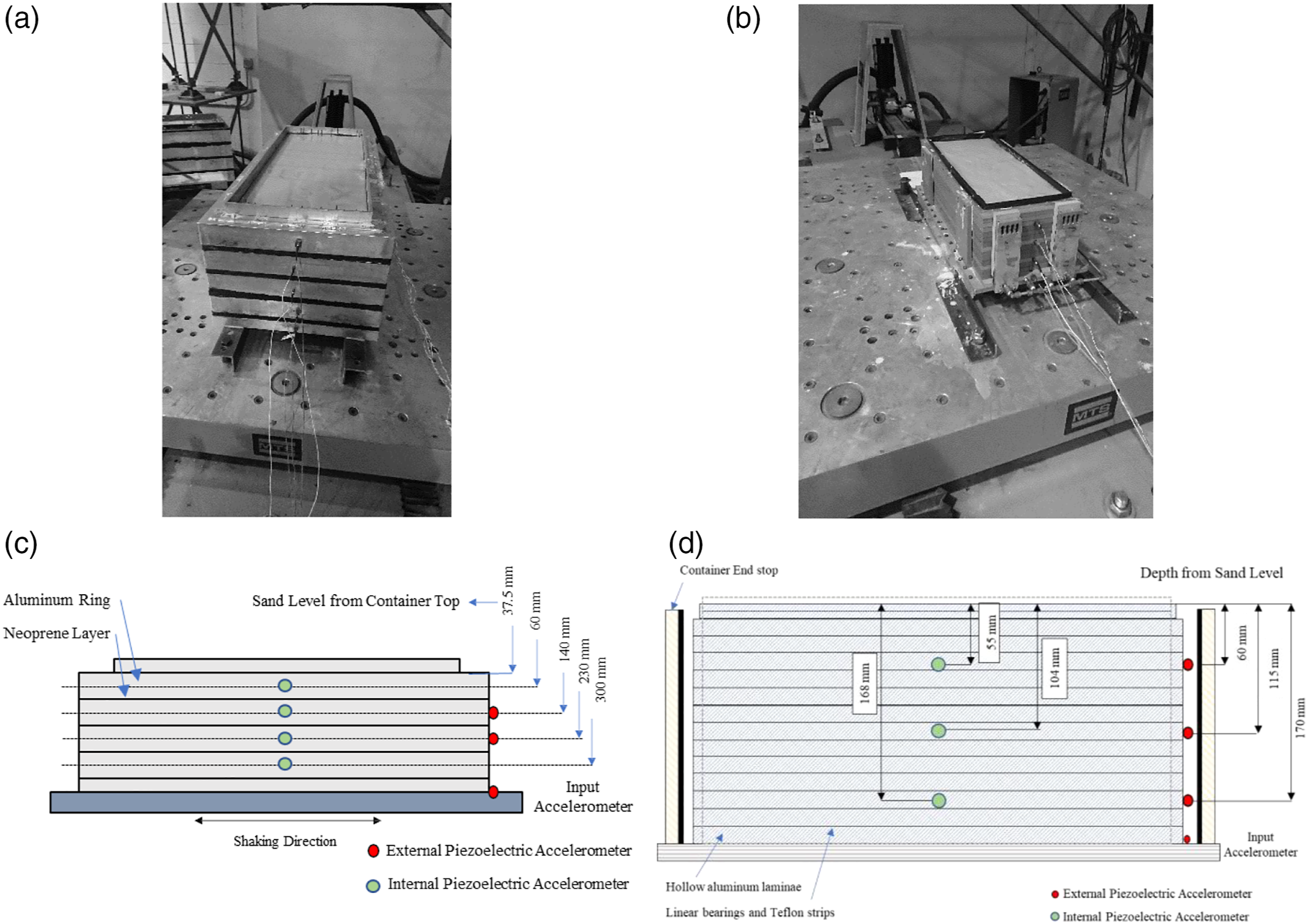
In this work, the empty containers were first tested with the ILC algorithm used to calibrate several different input motions. The calibrated motions were then applied to each container filled with a dry sand deposit and a saturated sand deposit. The sand deposits were created using CIEST’s automatic spot pluviator. This functions similarly to a 3D printer and allows for samples with repeatable properties to be created. By reducing the height from which the sand was poured and the nozzle aperture, sand deposits with a low density were created, that is, with large voids between the grains yielding a ‘loose’ packing. Both containers featured inlets leading to low porosity stones at their base to allow controlled ingress of water from the base upwards to achieve a high degree of saturation in the sand. During shaking, the dry and saturated loose sand deposits are expected to exhibit a moderate and large change of stiffness, respectively. Concurrently, the material damping and thus overall payload damping will be affected.
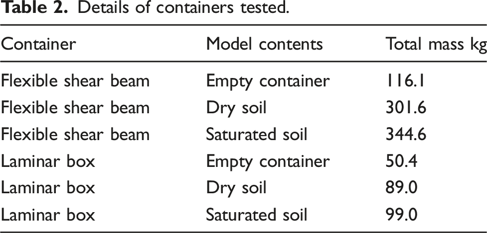
Details of containers tested.
Details of motions applied to each container discussed in this study.
3. Experimental results
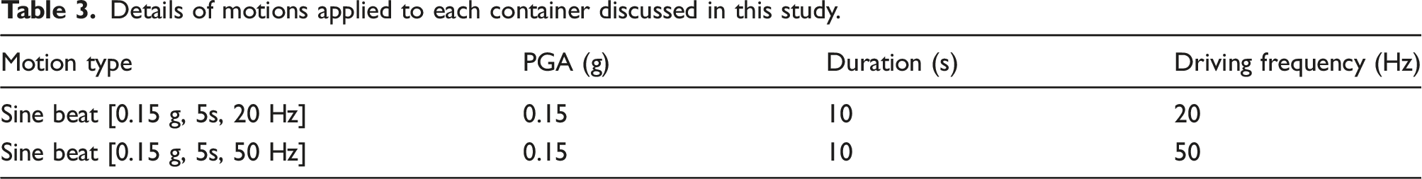
The process of calibrating the motions for the empty containers is illustrated for the 50 Hz sine beat motion in Figure 3. Figure 3(a) shows the drive signal outputted by the automated ILC algorithm and resulting table acceleration measured at the first, intermediate and final iterations. The gradual build-up of amplitude, marginal overshoot and final reduction of the drive signal to achieve the 0.15 g target magnitude is evident. Figure 3(b) compares the demanded and achieved table acceleration with the optimized drive signal in the time domain and following a wavelet transform of the signals. The clear similarity between the demanded and achieved frequency content at all times is apparent, with only minor additional energy at the 3rd harmonic of the input motion. Illustrative iterative closed loop tuning of empty FSB container, that is, with fixed stiffness: (a) examples of pulses produced by ILC algorithm converging towards the target motion and (b) comparison of the demanded and achieved acceleration time histories with the final achieved acceleration from the optimized drive signal and corresponding wavelet transforms to show the frequency content as a function of time.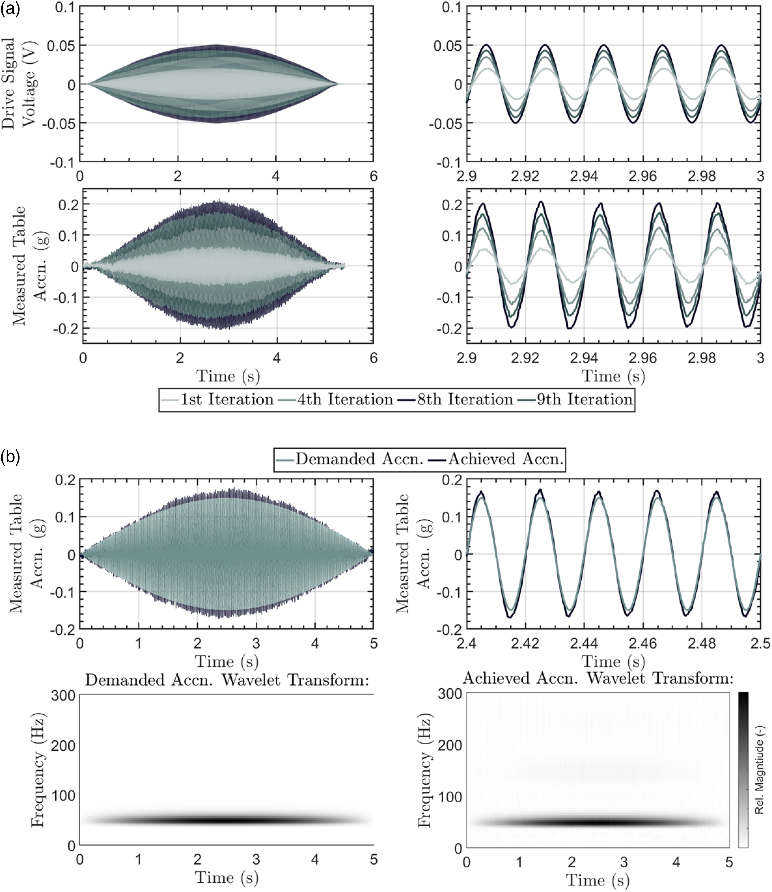
The process of calibrating the input motion with a similar proxy mass but without the actual test payload – and crucially one with a fixed overall stiffness – reflects typical testing procedures in geotechnical, structural and other engineering sectors. The same steps are carried out for each applied motion detailed in Table 3. The results from using the calibrated input motion for test payloads that can exhibit moderate and large changes of stiffness are firstly explored for the FSB tests.
3.1. Flexible shear beam results
Subject to the same drive signal, the achieved input accelerations for the empty FSB box and configurations filled with dry and saturated sand are shown in Figure 4. The results from the 0.15 g 20 Hz and 50 Hz motion are shown in terms of the time histories and wavelet transforms. The frequencies were chosen to be far away and closer to the natural frequency of the empty container that was numerically determined during its design (63.8 Hz; (Paramasivam, 2018)). Comparison of the target and achieved input acceleration time histories and wavelet transforms for the 20 and 50 Hz sine beats between the empty, dry sand and saturated sand FSB configurations.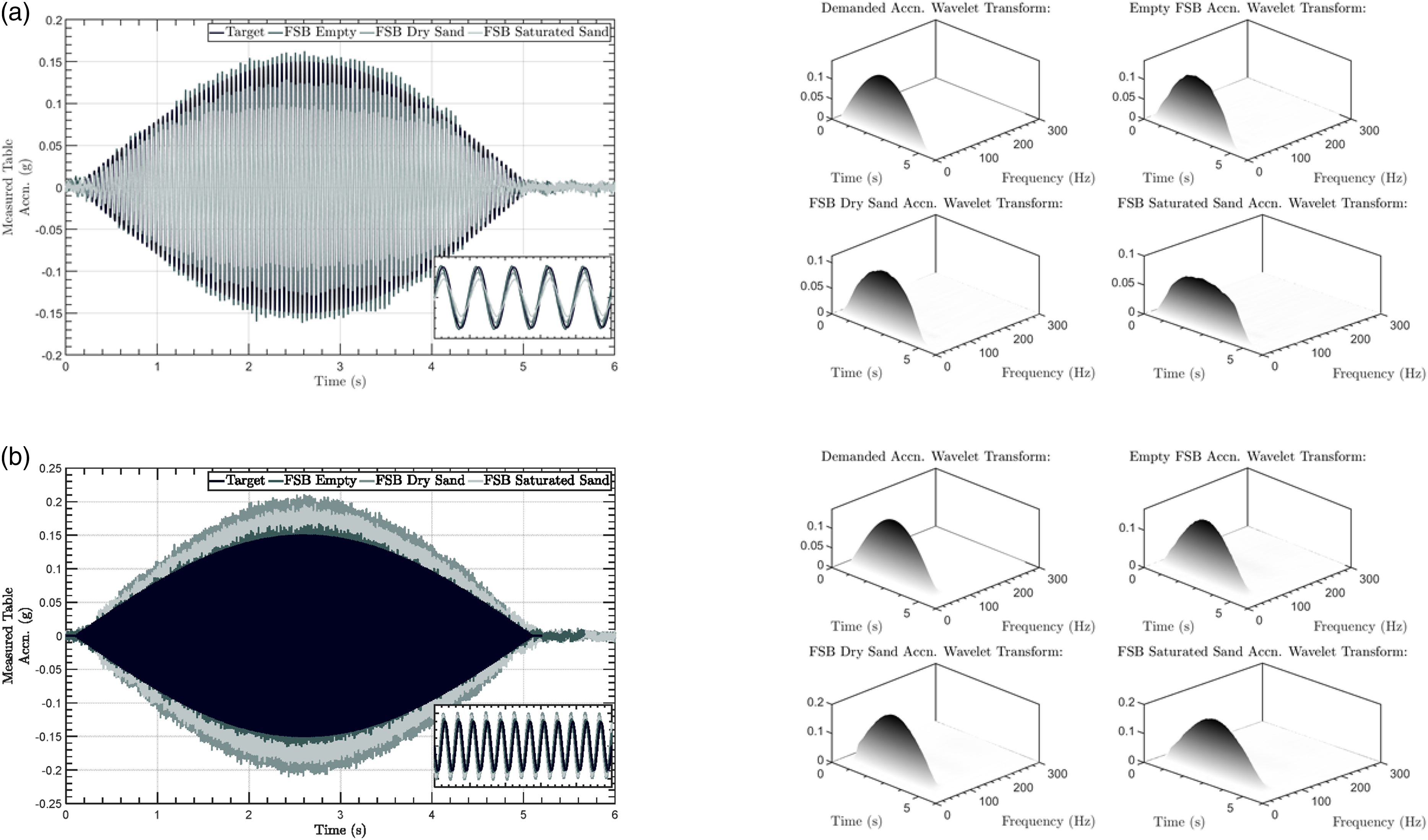
It is clear from Figure 4 that the discrepancies between the demanded and achieved accelerations are primarily in terms of the acceleration magnitude and not frequency content. Further, the error is consistently different between the empty FSB and with dry or saturated sand. This illustrates that using the drive signal optimized for the empty FSB container is not optimal for the different test configurations.
Figure 5 shows the calculated error between the demanded and achieved base accelerations. For both motions, and as expected, the error is smallest for the empty container the ILC algorithm calibrated the drive signal for. However, for the 20 Hz motion in Figure 5(a), the error is greater for the saturated sand versus the dry sand, whilst for the 50 Hz motion shown in Figure 5(b), the situation is reversed. These trends evidence that the discrepancy is not purely due to the differences in payload mass between the empty, dry and saturated cases. This highlights the importance of the dynamic response of the system which is a function of the payload mass, stiffness and material damping. The form of the error time histories following the input motion should be interpreted as an artefact of considering absolute errors rather than a dependence on the amplitude of the demanded motion. Calculated error between demanded and achieved base accelerations for the different FSB test configurations and applied motions.
To further investigate this point, the change of the soil shear stiffness inferred from the vertical propagation of the shear waves measured using the external and embedded horizontal accelerometers is considered. Illustrations of the acceleration data used are shown in Figure 6(a). Both amplification and attenuation of the vertically propagating accelerations can occur due to the container and soil vibration modes, generation of excess pore pressures within the soil body and varying material damping. This influences the cyclic shear stresses experienced and soil stiffness mobilized. Using the acceleration data, equivalent density and instrument height, the dynamic shear stress–strain loops for each cycle of applied motion can be constructed, as shown in Figure 6(b) and (c). The procedures described in Brennan et al. (2005) and Zeghal & Elgamal (1994) were followed with a bandpass filter set at 10–500 Hz. Essentially, the dynamic stresses are derived from inertial considerations whilst the dynamic strains are inferred from double integration of the acceleration time histories to obtain relative displacements. Further, the secant stiffness can be inferred from each complete dynamic shear stress–strain loop (i.e. the average stiffness for a given cycle). Inferring the change of secant stiffness of the payload during the applied shaking: (a) time histories of horizontal accelerations measured on the empty FSB and within the dry and saturated soil during the 50 Hz shake. Dynamic shear stress–strain loops and progressive secant stiffness with time for the (b) 20 Hz motion and (c) 50 Hz motion.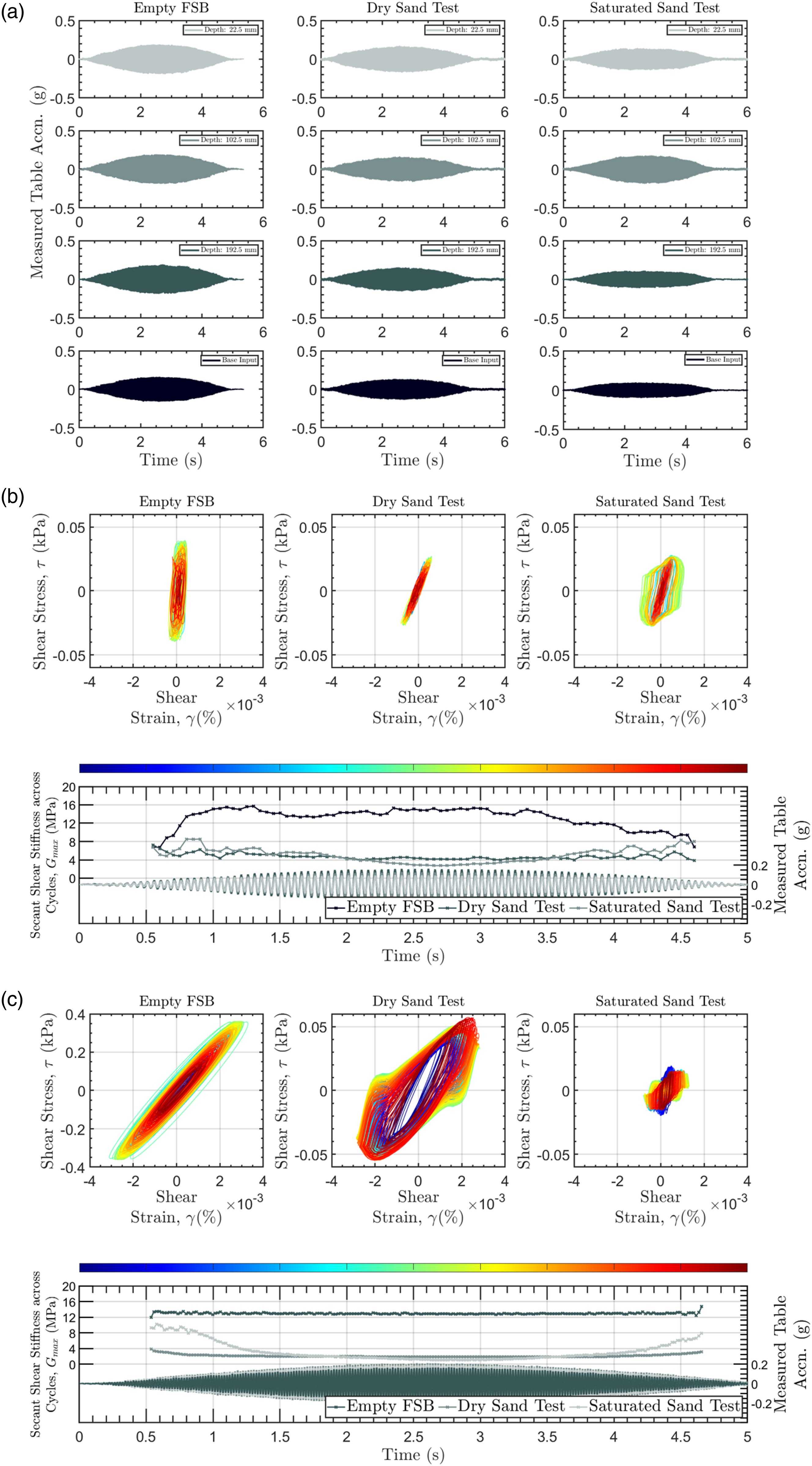
Figure 6 confirms that the empty FSB, particularly for the 50 Hz motion, experiences negligible changes of stiffness during the shaking. In the case of the 20 Hz motion, the values generally fluctuate around the same constant value obtained from the 50 Hz motion. Whilst part of the oscillations could be due to the empty container stiffness depending on the strains mobilized, the lower signal to noise ratio in the measurements when small strains are induced (c.f., strains of <0.5 milli-ε in Figure 6(b) vs 3.0 milli-ε in Figure 6(c)) is likely also producing uncertainty, particularly as the container materials were all behaving elastically. By contrast, Figure 6(b) and (c) show that the payloads with soil experience observable changes of stiffness during the applied motions. The dry sand test generally shows less stiffness reduction during the applied motion, whilst the saturated sand, particularly for the test subject to the 50 Hz motion, showed significant variations. In absolute terms, the lower initial cyclic stiffness for the dry sand in Figure 6(c) can be justified by the larger cyclic shear stresses experienced (i.e. the shear waves are amplified and not attenuated in dry sand) which degrades the initial sand stiffness (e.g. Hardin & Drnevich (1972)).
The effect these stiffness changes have on the achieved base motion can be clarified by calculating the maximum absolute error between the demanded and achieved base motion per cycle versus the secant shear stiffness across cycles, as shown in Figure 7. The trends obtained strongly suggest that the error between the demanded and achieved base motions depends on the secant shear stiffness of the payload; as the average stiffness of the payload reduces away from the empty FSB values, the error is seen to increase in both Figure 7(a) and (b). Thus, the drive signal optimized by the ILC algorithm based on the empty FSB container response is less effective as the payload stiffness changes, and in this case reducing as the soil strains and/or generates positive pore pressures. The data in Figure 7 suggests that broadly there is an inverse relationship for these cases, though the change of payload mass and characteristics of the input motion (e.g. in this case frequency content) is also observed to matter. Further, the material damping, for example, indicated by the enclosed area of the stress–strain loops, was not independently controlled but conceptually would also affect the shake table – payload interaction. Comparison of the calculated maximum absolute error per cycle versus the secant shear stiffness across cycles from the FSB tests for (a) 20 Hz motion and (b) 50 Hz motion.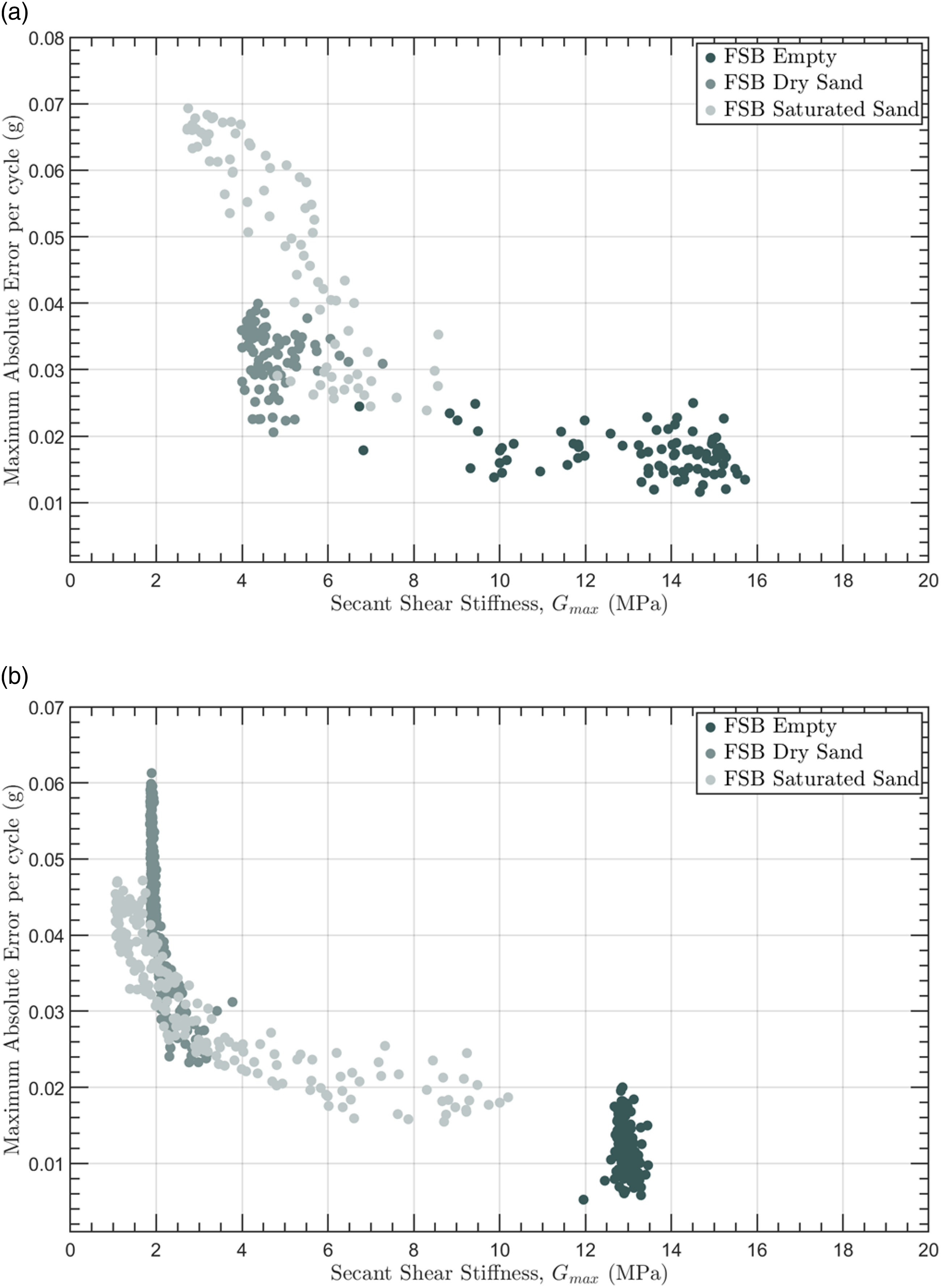
3.2. Laminar box results
A similar analysis can be carried out for the tests conducted within the laminar box. Key differences to note include the lighter payload and smaller differences of total mass between the empty, dry and saturated soil tests. Thus, the larger shake table to payload mass ratio can better isolate the role of the changing payload stiffness on the performance of the optimized drive signal. However, an additional complexity is that the laminar box, when empty, is designed to have negligible mass (by using hollow aluminium sections) and particularly stiffness (due to the Teflon strips and roller bearings between layers). This makes it ideal for testing soil samples that can show large stiffness reductions (e.g. during soil liquefaction) but unsuited to be the base case for the ILC drive signal optimization as done for the FSB box which has a finite and reasonably constant stiffness when empty. Thus, the drive signal was optimized without inclusion of the laminar box.
Figure 8 presents comparisons between the target and achieved input motions and the time history of the error between them for the 20 Hz input motions. Due to the large settlement the soil developed during the 20 Hz motions, the results from the subsequent 50 Hz motion are not presented. Broadly, the absolute errors are larger for all cases than those observed with the FSB box. In the case of the 20 Hz motion, the accelerations are consistently less than targeted. Video recordings of the table motions confirmed that the laminar box did not contact the end stops during any of the applied motions; the errors can be fully ascribed to the previously optimized drive signal not accounting for the payload response. Again, as the trend of errors does not follow the trend of increased mass between the empty, dry and saturated sand payloads, the importance of the payload stiffness is further demonstrated. Comparison of accelerations for the 20 sine beat between the empty, dry sand and saturated sand laminar box configurations in terms of (a) the target and achieved input acceleration time histories and wavelet transforms and (b) time histories of errors between the achieved and desired table motions.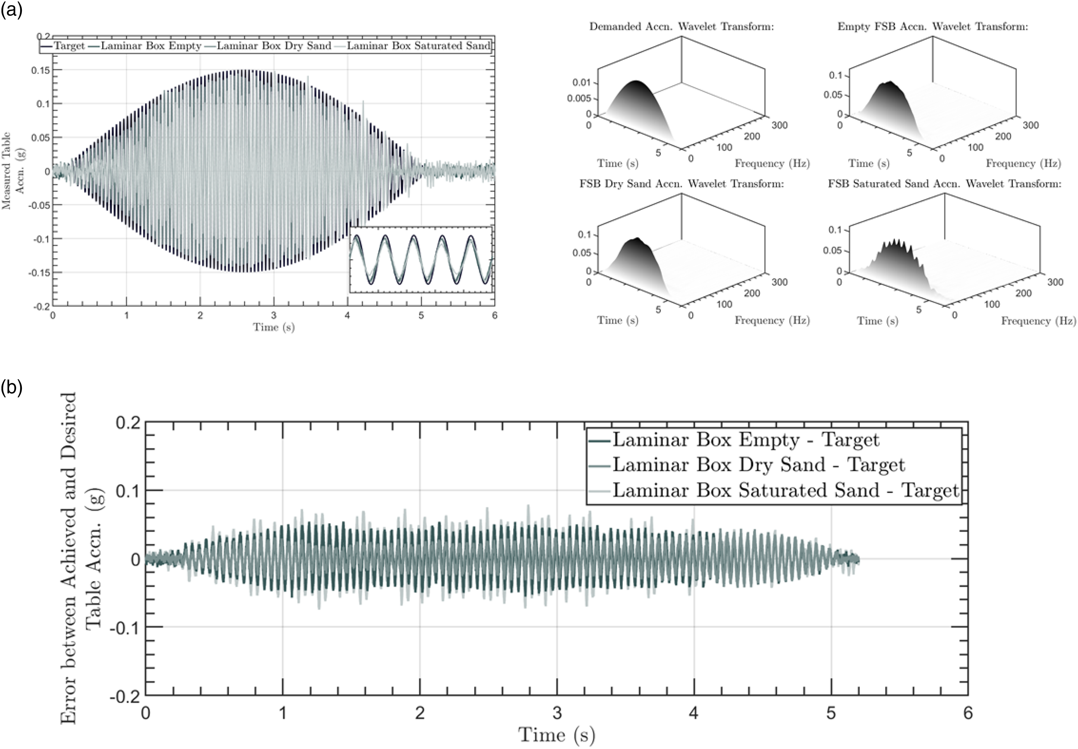
Following from Figure 8, the dynamic stress–strain loops in Figure 9 show the marked difference of the empty laminar box response; the light laminae attract much smaller inertial loads but still slide leading to small equivalent stiffnesses. When the laminar box contains dry sand, the response is consistently stiffer, remaining quite constant during the 20 Hz motion. The saturated sand response is initially stiff but quickly degrades due to the positive pore pressure generation, with the overall payload stiffness eventually matching the empty laminar box case. However, within a given cycle, the saturated sand response is more complex and not necessarily well characterized by a secant shear stiffness across the cycle. Liquefied soil can be described as having a ‘banana shape’ of shear stress versus shear strain; across a single cycle, it will have a low tangent stiffness during the initial straining when positive excess pore pressures are generated before suddenly showing a large increase of tangent stiffness as dilation induces negative excess pore pressures for the same shearing but with smaller contact stresses between the grains (also described as the soil crossing the phase transformation line, e.g. Ishihara et al. (1975)). Inferring the change of stiffness of the payload during the applied shaking from dynamic shear stress–strain loops and progressive secant stiffness across cycles during the 20 Hz motion.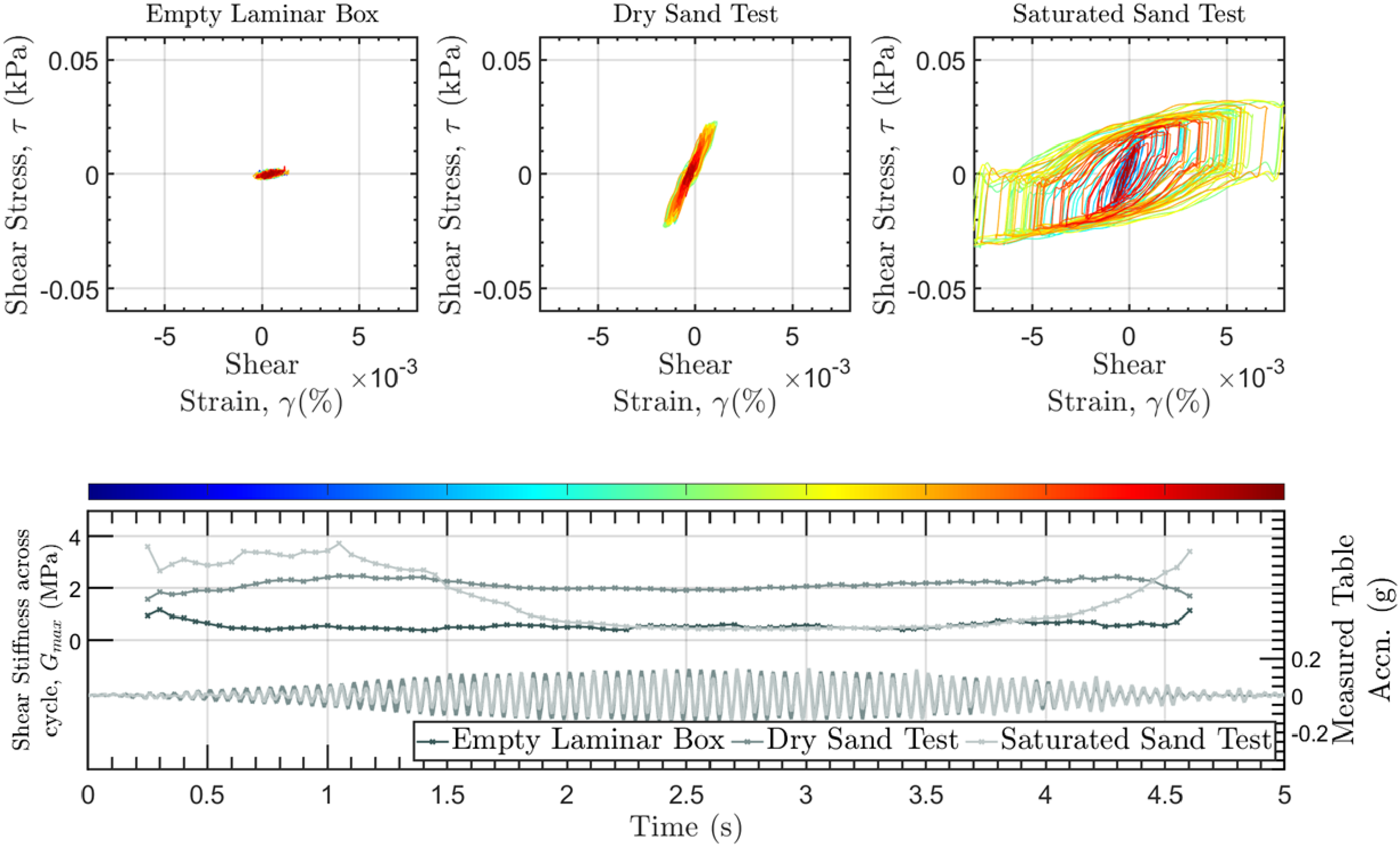
Finally, the effect of the dynamic payload response inferred from Figure 9 on the achieved base motion is shown in Figure 10. Despite some scatter, Figure 10 shows similar trends to those observed in Figure 7; as the secant shear stiffness across a cycle is reduced, the error between the demanded and achieved acceleration increases. The overlap of the datasets from the empty laminar box and saturated sand test at low stiffnesses further strengthens the hypothesis, in addition to the clear separation of the lower overall errors observed for the dry sand test with a larger secant shear stiffness. The larger scatter may be ascribed to the laminar box better allowing the saturated soil to liquefy that results in rapid stiffening of the soil in each cycle and larger damping observed that will both influence the overall dynamic response and shake table payload interaction. Comparison of the calculated maximum absolute error per cycle versus the secant shear stiffness across cycles from the laminar box tests for (a) 20 Hz motion and (b) 50 Hz motion.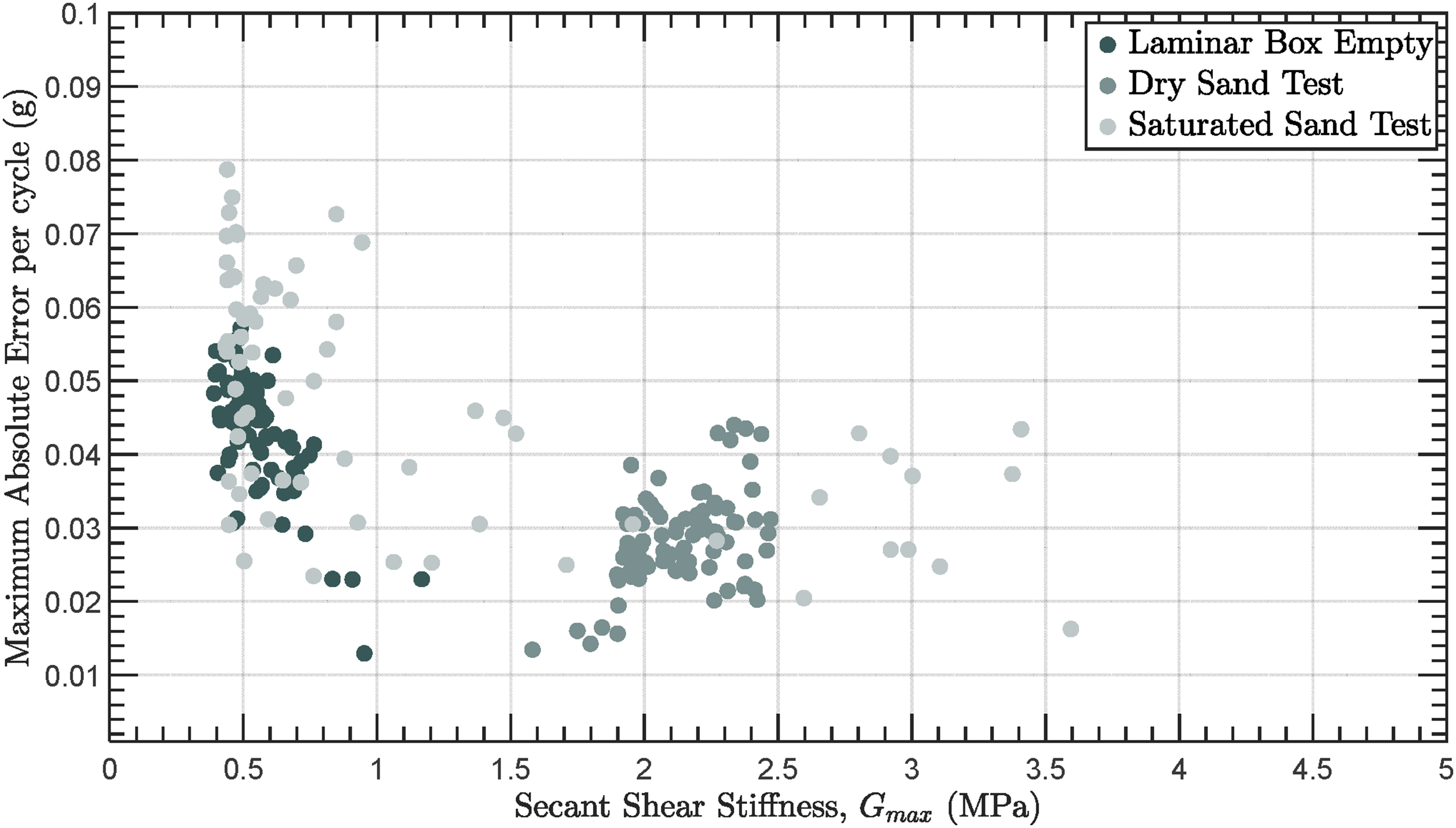
4. Conclusions
This study presents an experimental investigation into the influence of a changing payload stiffness on ILC strategies commonly used across multiple engineering sectors for shaking table tests. Combined instantaneous PID control and ILC strategies applied to test payloads and across longer time windows have been previously demonstrated to address the respective weaknesses of both approaches. This includes non-linearities of the system response, difficulties with manual tuning of the shake table, sensitivity to drifts in the motion or its derivatives, phase lags between the current and measured table motion or interaction between the shake table and payload.
However, historically the design of the test payload to optimize drive signals has exclusively focused on matching the mass of the real payload. In this study, the importance of the payload stiffness on the base motions ultimately achieved has been experimentally demonstrated. The influence of the stiffness for cases where the payload mass was significantly smaller than the table mass and actuator capacity was also shown. In cases where the ILC was used to optimize the motion for a stiff payload, plots of the error between demanded and achieved acceleration per cycle versus the secant shear stiffness of the payload across that cycle showed an approximately inverse relationship; that is, the error increased as the payload stiffness degraded.
More broadly, the results presented highlight the experimental challenges that can be encountered (e.g. significant errors between the demanded and achieved input motions) when accurate, precise, and repeatable input motions must be applied to payloads with specimens that can exhibit a complex material response over a small number of loading cycles. For many cases, system mathematical models cannot be used to test the performance of control strategies prior to the experiment. For example, there is presently no accepted theory or mathematical model that can wholly predict the constitutive material response of multi-phase, granular media such as saturated soils. Nevertheless, such materials are routinely tested using shaking table tests in experimental programs. These are presently limited in terms of assessing and/or comparing the performance of single or multiple civil engineering systems due to input motions that vary due to the dynamic response of the payload.
The interpretation of experimental results presented herein, specifically a focus on comparing the discrepancy between the achieved and demanded motions versus the payload dynamic response characterized by the progressive stiffness of the payload (e.g. the cyclic secant stiffness), could be utilized in future studies to both assess the experimental study and benchmark different control approaches (e.g. either ILC or other open or closed loop, iteratively updated schemes) for testing across different engineering sectors where the dynamic response of the payload influences the shake table performance.
Overall, the results from this study can be used to recommend that efforts to use ILCs to optimize drive signals using test payloads should seek to match both the real payloads mass and stiffness when possible. In this case, the material damping that must also influence the shake table–payload interaction will also be implicitly captured. However, the trends observed suggest that the error is not necessarily mitigated or bounded by using test payloads that are either much stiffer or much softer than the real payload. A limitation to this recommendation will be if the test payload can exhibit more complex cycles of stiffness during shake table testing, e.g. saturated soils where in a single loading cycle the excess pore pressures in the pore fluid can cycle between positive and negative, thus softening and stiffening the bulk material response. In these cases, short of using the ILC with a test payload that replicates the real payload stiffness changes and overall dynamic response, it may be possible to determine whether undershooting or overshooting the target motion is preferable and select a test payload at the lower or higher range of excepted stiffnesses on a case-by-case basis. At present, experimental methods may be the most effective way to test ILC and other open or closed loop, iteratively updated control strategies as the numerical prediction of the dynamic response of a variety of payloads that contain geotechnical or other highly non-linear, stress, strain and rate dependent materials in terms of constitutive response are not readily modelled in isolation, let alone within a numerical model of the controller system and hardware.
Footnotes
Acknowledgements
The first author is grateful for the assistance from the graduate research students from their Boulder Geomechanics and Geohazards Research Group. All authors are grateful to Mr Michael Scott Cusack for his practical assistance and advice, and the Brno University of Technology’s Exchange Program.
Declaration of conflicting interests
The author(s) declared no potential conflicts of interest with respect to the research, authorship, and/or publication of this article.
Funding
The author(s) received no financial support for the research, authorship, and/or publication of this article.