
Abstract
Two different Tuned liquid dampers (TLDs) were installed on the floors of a three-floor structure. The TLD natural frequencies were tuned to the first two resonance frequencies of the structure, and its base was subjected to harmonic excitation. The excitation frequency of the sweep tests ranged from 0.8 to 3.2 Hz, and the mass ratio for all the simulations was constant and equalled 2%. The FVM/FEM method was used to solve the fluid-structure coupling, and the maximum displacement of the three floors were obtained. The dissipated energy by damping force was used to study the coupling mechanism of TLD and multilayer structure. Findings indicated that the scheme of the multiple-TLD design was stable and effective, which ensured that the structure-TLD system under the same mass ratio had no local adverse effects. The proportion of positive work time of tank hydrodynamic force is the intuitive embodiment of TLD damping performance. The frequency doubling effect generated by the sloshing nonlinearity in TLD has been confirmed for use in the vibration control of higher-order modes of structures. On the premise of constant mass ratio, it is suggested to adopt a multi-TLD damping system, in which each damper is installed at the height of the maximum displacement of each structural mode.
Keywords
1. Introduction
Tall and slender offshore structures are susceptible to seismic, wave and wind loads. The induced vibrations would reduce the service life of the structures and affect the operation of the equipment (Pabarja et al., 2019; Wang et al., 2019). The lightweight and high strength materials have made the structures lighter and more flexible. However, the low inherent damping always leads to ambient vibrations (Alhaddad et al., 2020; Suthar and Jangid, 2021). Auxiliary damping devices have been widely adopted to mitigate the low order modal response of structures. Passive damping devices such as Tuned Mass Dampers (TMD), Tuned Liquid Column Dampers (TLCD) and Tuned Liquid Dampers (TLD) have been proposed in offshore structures (Jahangiri et al., 2021; Ghasemi et al., 2019; Jin et al., 2014), which have the advantages of easy installation, low maintenance and no external energy input (Ashasi-Sorkhabi et al., 2017). The TLD damping system consists of one or more tanks filled with liquid, which has lower maintenance and installation cost. The TLD damping effect in suppressing slight amplitude vibration of slender structures is better (Ghaemmaghami et al., 2016). In addition, the structural damping can be increased by a reasonable tank design for the equipment with a liquid storage function.
Sloshing in the tank is the primary damping mechanism of TLDs. When the direction of hydrodynamic force is opposite to the velocity of the structure, the structural response can be controlled. Many investigations have been conducted for sloshing, where the primary methods include analytical solutions, numerical methods and model tests. Faltinsen (1978) presented an analytical solution for two-dimensional flow in a rectangular tank to calculate free surface elevations under horizontal excitation. A theoretical approach was developed to describe the second resonance of a rectangular tank with a slatted screen and predict steady-state wave elevations by Faltinsen and Timokha (2010). A linear analytical solution of 3-D liquid sloshing under the coupled surge and sway excitation was developed by Liu and Lin (2008). However, significant discrepancies are developed under large excitation amplitude.
The hydrodynamic and structural characteristics of violent sloshing in elastic tanks have been studied through a physical model test by Jiang et al. (2015). Lee et al. (2006) observed strongly nonlinear sloshing flows in LNG and the results indicated that physics-based numerical schemes are essential in predicting violent sloshing flows and sloshing-induced impact pressure. The sloshing force acting on the tank can be utilised to suppress vibration for slender structures, and the coupling effects with buildings (Tait, 2008; Rai et al., 2017), jacket platform (Jin et al., 2014; Hokmabady et al., 2019) and offshore wind turbine (Zhang et al., 2016; Park et al., 2021) have been investigated by physical tests. Numerical methods have achieved rapid development, which contain finite difference method (Wu and Chen, 2009; Xue and Lin, 2011), finite element method (FEM) (Cho and Lee, 2004), finite volume method (FVM) (Kargbo et al., 2019; Xue et al., 2022) and smoothed particle hydrodynamics (Green et al., 2021; Jena and Biswal, 2017; Zhang et al., 2014) to simulate violent sloshing. The experiment effectively validates the analytical and numerical methods to evaluate the nonlinear hydrodynamic load and wave breaking of violent sloshing.
The interactions between TLD and structure are mutual. The method only considered the hydrodynamic force of fluid on the structure, or the structural deformation on the fluid is one-sided, which can only meet the solution under the condition of linear motion and small amplitude. Tao et al. (Tao et al., 2018) developed a two-way coupled solution, which completed the simulation and experimental validation of the air valve through FVM. Seo et al. (Seo et al., 2017) studied the relationship between sloshing and ship added resistance. Fu et al. (2018) adopted the separated solver, which combined FVM and FEM to propose an oscillator-liquid combined damper (OLCD), where a movable mass block was installed in the damper. The results found that the vibrator mass block can dissipate the system energy by enhancing the shear flow. Altunisik et al. (2018) built the coupling test model of TLCD and flexible support prototype structure in the laboratory. The results indicated that the vibration control effect of the TLCD on length direction was 94% higher than that in the vertical direction, and the effect of TLCD on lateral excitation was significantly reduced.
Pabarja et al. (2019) established a three-story steel structure and studied the TLD damping performance on different floors. It was found that the displacement and acceleration control effect was the best when the TLD was installed at the top of the structure. However, the roof amplitude increased when the excitation frequency reached the second-order resonance frequency. The structural model built in the laboratory increased the test cost and complexity, and the natural period of fixed coastal structures may be changed due to the sediment transport (Li et al., 2021). The effects of mass and tuning ratio on TLD performance are analysed by Ashasi-Sorkhabi et al. (2017) with real-time hybrid simulation (RTHS). From the perspective of energy dissipation, it was found that the best effect can be achieved when the mass ratio is less than 3% and the tuning ratio is 1.2.
Lee et al. (2007) also simulated the control effect of the three-layer support structure under seismic excitation through the RTHS device and focused on the sloshing and slamming phenomena in the container. They believed that the instantaneous slamming was related to the fluid quality, resulting in the nonlinear characteristics of the structural motion response. To study the energy dissipation of the TLD, Cavalagli et al. (2017) connected an induction loop between the shaking table and the tank to obtain the shear force between the water tank and the shaking table and evaluated the energy dissipation by the integral area in the hysteresis loop.
Recently, combined dampers with TLD and TMD have been widely investigated. Xu et al. (2018) considered that a tuned mass immersed in the TLD could improve the damping performance by numerical decay test. A hybrid TMD-TLD proposed by Chen and Yang (2018) can reduce the maximum displacement by 70%. However, the mistuning may happen because of the added mass of the damper. Love and Lee (2019) obtained the nonlinear performance of structural response with the combined damper. The results indicated that the coupled system could significantly reduce the resonant response of slender structures.
In previous research and applications, the natural frequency of TLDs has been consistent with that of the structure because the low-order modal resonance is more dangerous. However, for slender structures, the higher modes vibrations usually contribute a lot in their responses especially subjected to base excitations (Wang et al., 2021). There are signs that the frequency doubling caused by the nonlinear effect of the sloshing phenomenon may increase the high-order response (Yu et al., 2019). To investigate the frequency doubling effect on different structural modes and analyse the damping mechanism of the TLD, an FVM/FEM method was used to simulate the TLD’s damping effects on a three-floor structure, where the second mode approaches three times the TLD’s natural frequency. The fluid solid interaction (FSI) method has the advantages of fast computing speed, high accuracy and low memory requirements. The positive and negative work done by hydrodynamic forces in the TLD is extracted separately and analysed quantitatively.
The model size of the three-floor structure and the TLD are introduced in the next section. Then, the fluid-structure coupling numerical model is given in Section 3, which includes the sloshing validation. In Section 4, the vibration control characteristics of TLD on a three-floor structure are evaluated, and the influence of TLD installation location on the damping performance is discussed. Section 5 presented the comparison of hydrodynamic energy dissipation of TLD under different resonant modes. Lastly, the study is concluded in Section 6.
2. Structural design
2.1. Supporting structure parameters
To study the influence of TLD damping characteristics on higher mode shape of the structure, a three-floor elastic support platform was designed in Figure 1. The dimensions of the base plate were 500 × 500 × 5 mm, and the first to the third floor were 600 × 600 × 5 mm. Four vertical columns with a size of 4.8 × 50 × 1000 mm were used to support each floor. When the bottom was set as fixed support, through finite element modal analysis, the elastic structure's first (FS1) and second (FS2) natural frequencies were 1.04 Hz and 3.02 Hz, respectively. And the first (TS1) and second (TS2) natural periods were 0.96 s and 0.33 s, respectively. The corresponding vibration modes of the first two orders are shown in Figure 1(a). It can be seen that the maximum horizontal displacement of the first mode shape appeared on the third platform, and the second mode shape was on the first platform. The maximum displacements of the first two modes were 0.1664 m and 0.1669 m, respectively. The structure's material used in the calculation is 304 stainless steel with a density and Young's modulus of 7930 kg/m3 and 2 × 10¹¹ Pa, respectively. (a) The first and second mode shapes; (b) The three-floor structure for case E7.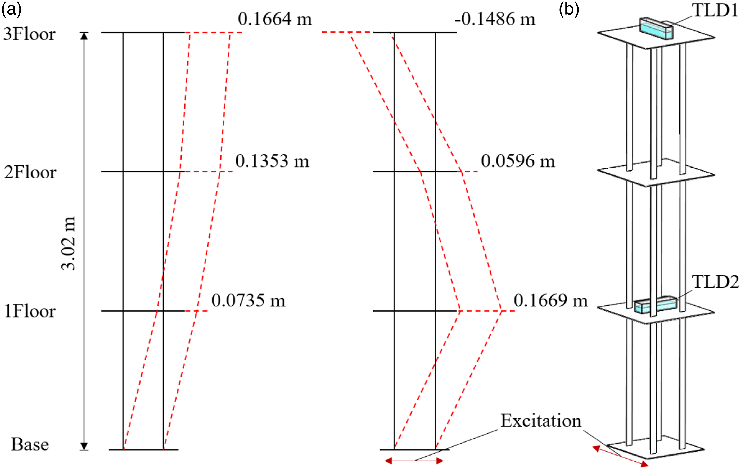
2.2. TLD parameters
The sloshing frequency in the tank is equal to the natural frequency of the TLD. The linear analytical solution of the rectangular tank’s natural frequency can be written as (Faltinsen, 1978)
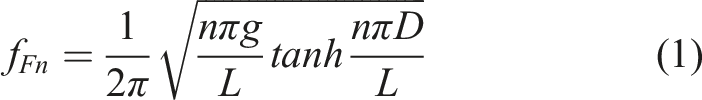
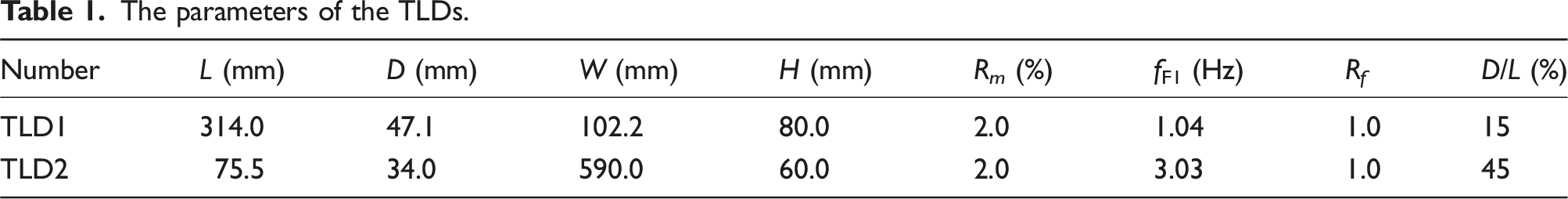
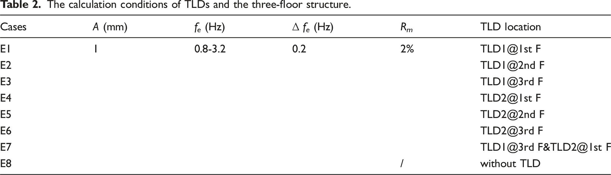
According to the dynamic response characteristics of the three-floor structure, two different TLD sizes (TLD1 and TLD2), whose damping frequencies correspond to the first two natural frequencies of the three-floor structure, were adopted, respectively. Although the damper with higher mass ratio could further suppress the structural vibration, by considering the frequency shift and energy dissipation, a 2% mass ratio is recommended to maximize the energy dissipation capacity of damper and avoid the negative effects of mistuning (Dou et al., 2020). Therefore, first, determine the natural frequency of TLD by adjusting L and D, and then further adjust the mass ratio by changing the water tank width W (the change of W is independent of the natural frequency of the tank). The view of the two dampers is presented in Figure 2. The TLD1 tuning ratio was 1.0, which corresponded to the first resonance frequency of 1.04 Hz, and the TLD2 was also equal to 1.0 but corresponded to the second resonance frequency of 3.03 Hz. To ensure that the dimension of the water tank does not exceed the side length of the floor, the filling ratio D/L of TLD1 and TLD2 was 0.15 and 0.45. It can be found that low-frequency damper (TLD1) required more extended space to increase the sloshing wave period; TLD corresponding to higher mode shape (TLD2) had less space demand. The specific parameters of the dampers are presented in Table 1. The view of TLD1 and TLD2. The parameters of the TLDs.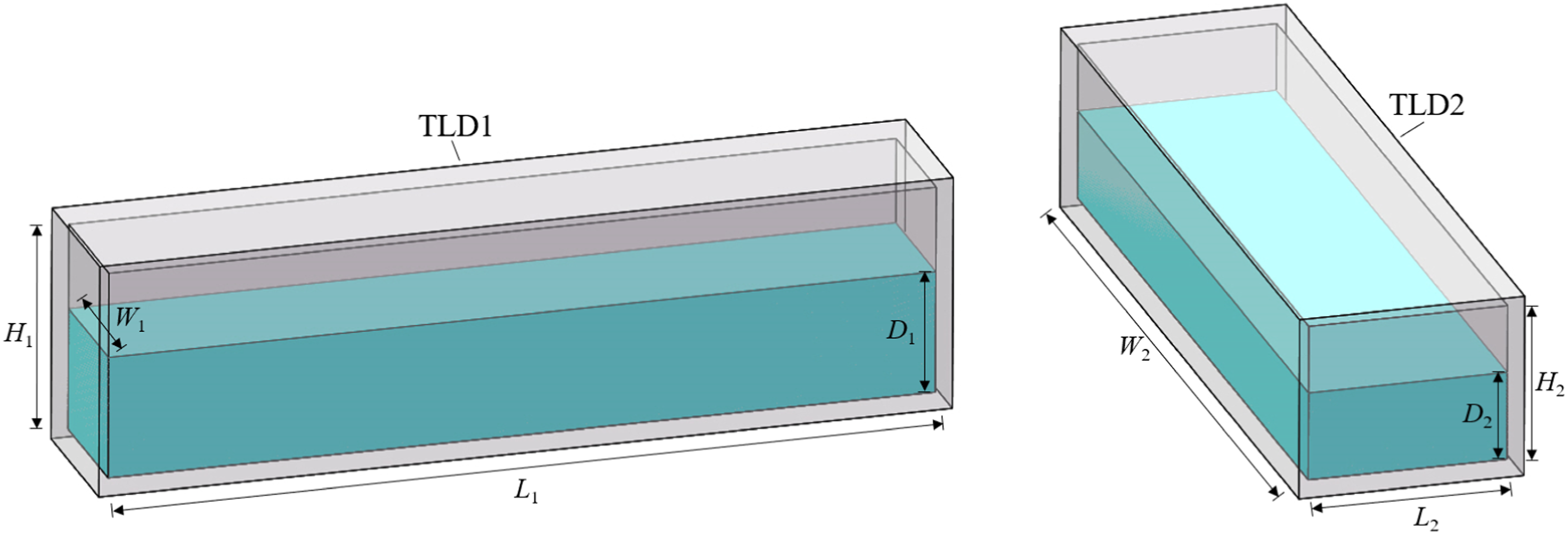
The calculation conditions of TLDs and the three-floor structure.
3. Numerical method
3.1. Governing equations
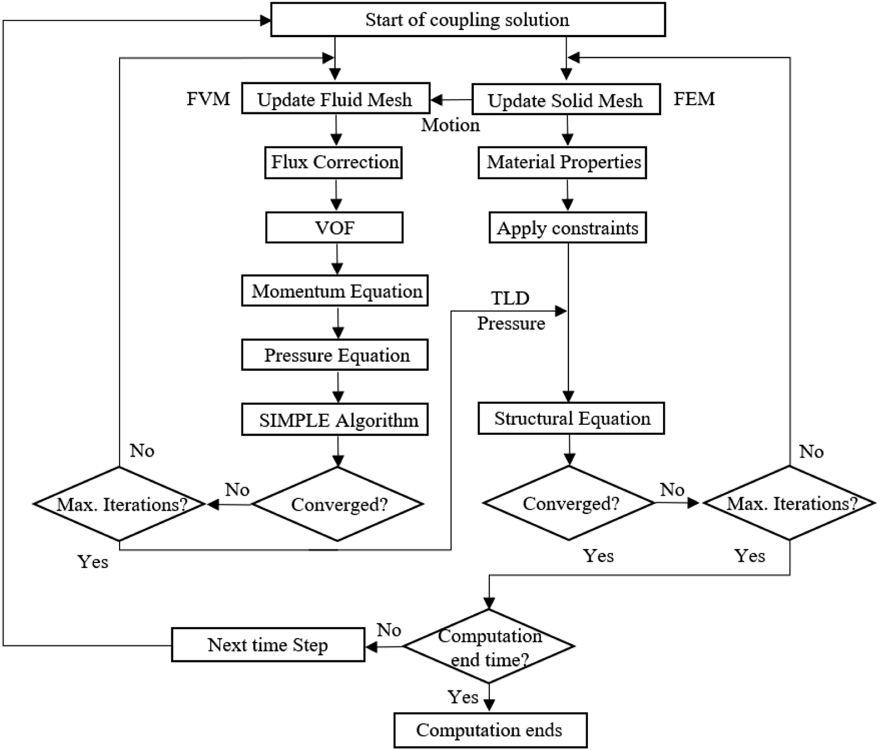
Simplified potential flow theory methods are challenging to simulate the highly nonlinear fluid sloshing. An FVM/FEM method was used to solve the fluid-structure coupling in the study to predict the interactions between the elastic structure and the TLDs. The load and deformation were transferred on the interfaces between fluid and solid, which indicated the induced sloshing waves generate a hydrodynamic force on the tank's walls. Meanwhile, the structures exert motion on them at the same time step. The transient performance was conducted on ANSYS Workbench, where Fluent and Mechanical solvers were coupled by the two-way iterative manner in the FSI simulation. The FEM solver simulated the structural domain to solve the equation of motion, and the fluid domain was simulated using the FVM to disperse the Reynolds Averaged Navier–Stokes equations. The above two solvers were two-way coupled when the results from one solver were treated as the boundary loads for the other solver. The detailed theory of the method can be found in the previous work (Dou et al., 2020), where the validation of the numerical method and the relationship of TLD energy dissipation between mass ratios and frequency ratios were emphasised.
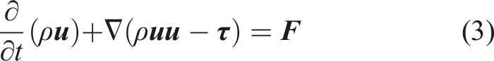
The two phases in the tank are assumed to be viscous, incompressible and immiscible, where the surface tension between water and air is 7.28 × 10⁻² N/m. FVM was utilised to discretise the computational domain of fluid. The governing equations, including conservation of mass and momentum, can be written as
The solid field consists of the empty tank and the supporting structure, and the tank was fixed on the roof plate where there was no relative displacement. The floor was subjected to sinusoidal excitation in the horizontal direction, and the solid domain was simulated by the finite element method that the incremental equilibrium equation used is
The separate solution method can solve the fluid and solid control equations in different solvers to avoid large discrete matrices and reduce the calculation cost. On the fluid-structure coupling interface, the equation is satisfied The diagram of two-way fluid-solid coupling solution.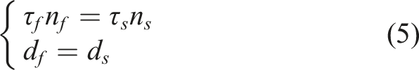
3.2. Mesh independence test
The calculation results of complex structures are more vulnerable to errors caused by the mesh. Three fluid mesh sizes (0.0014 m, 0.002 m and 0.0028 m) were adopted in the mesh independence test to evaluate the influence of fluid mesh on structural vibration. The horizontal displacement of the third and first floors with f
e
= 1.0 Hz in group E1 is shown in Figure 4. It can be observed that the time histories of the three floors in the first 7s under different mesh sizes were highly consistent. Displacement time histories of the floors. (a) The third floor; (b) The first floor.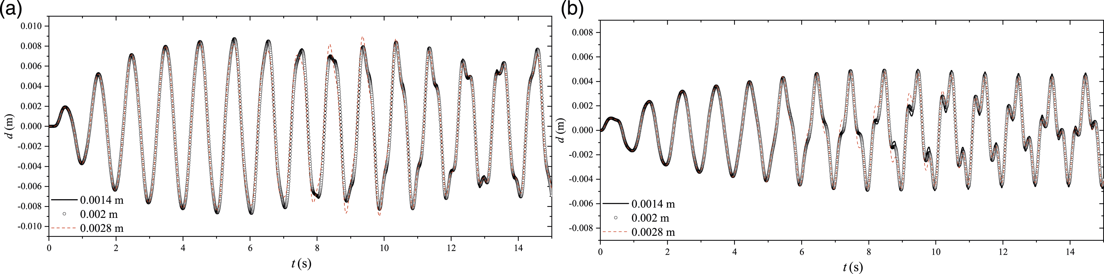
As the sloshing phenomenon becomes more and more severe, the accuracy of 0.0028 m mesh size in simulating nonlinear fluid motion decreased within 7s to 11s, but the average peak error remained within 2%. The results obtained at 0.002 m and 0.0014 m mesh sizes were the same. Thus, considering the calculation cost, the selected fluid mesh size scale was 0.002 m.
3.3. Numerical validation
Shaking table tests were carried out in the Laboratory of Vibration Test and Liquid Sloshing at Hohai University, China to ensure the simulation accuracy of the numerical method under resonant excitation. The rectangular tank with a dimension of 510 × 150 × 470 mm3 is shown in Figure 5, which is filled with water with 100 mm. Two pressure sensors were set on the left wall of the tank, which was 30 mm (P1) and 90 mm (P2) away from the bottom, to record the pressure change during the sloshing. Schematic diagram of the rectangular tank.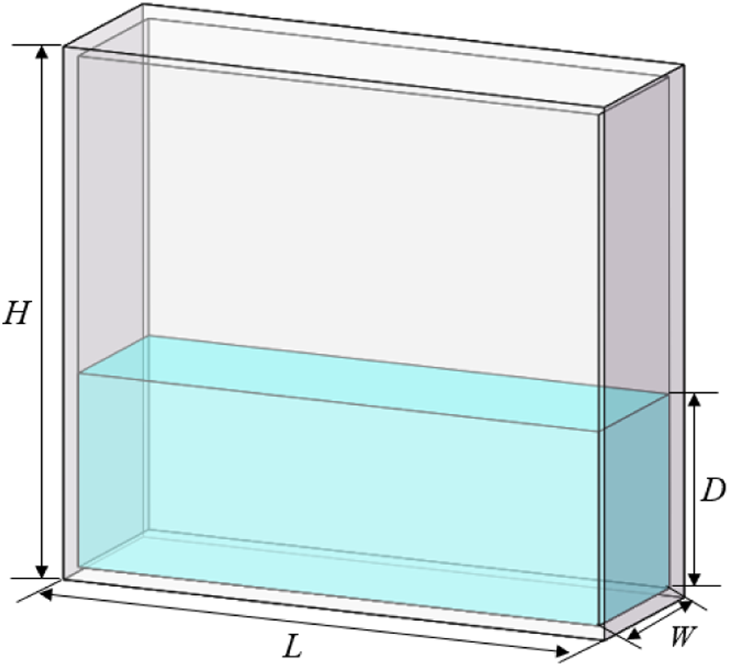
Figures 6 and 7 compare the time histories of the pressure on the left wall and the sloshing wave under resonant excitation, with A = 5 mm and f
e
= 0.915 Hz. P1 sensor was below the free surface, and the curve exhibits double peaks due to the impact of sloshing. The valley value of P2 sensor tends to be straight because the measuring point periodically floats above the free surface during sloshing, and there had almost no hydrodynamic load when exposed to the air. The straight line at the trough represents the deducted hydrostatic pressure. The straight line at the trough represents the deducted hydrostatic pressure. Time histories of two pressure sensors under resonance excitation. Comparisons of sloshing under resonance excitation.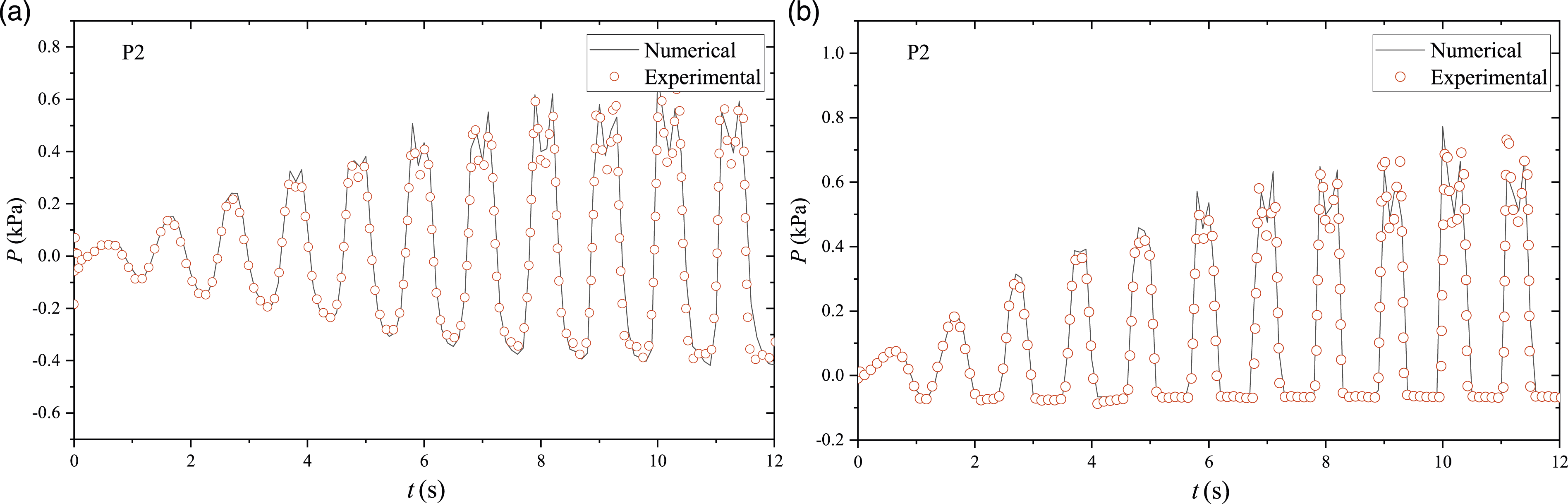
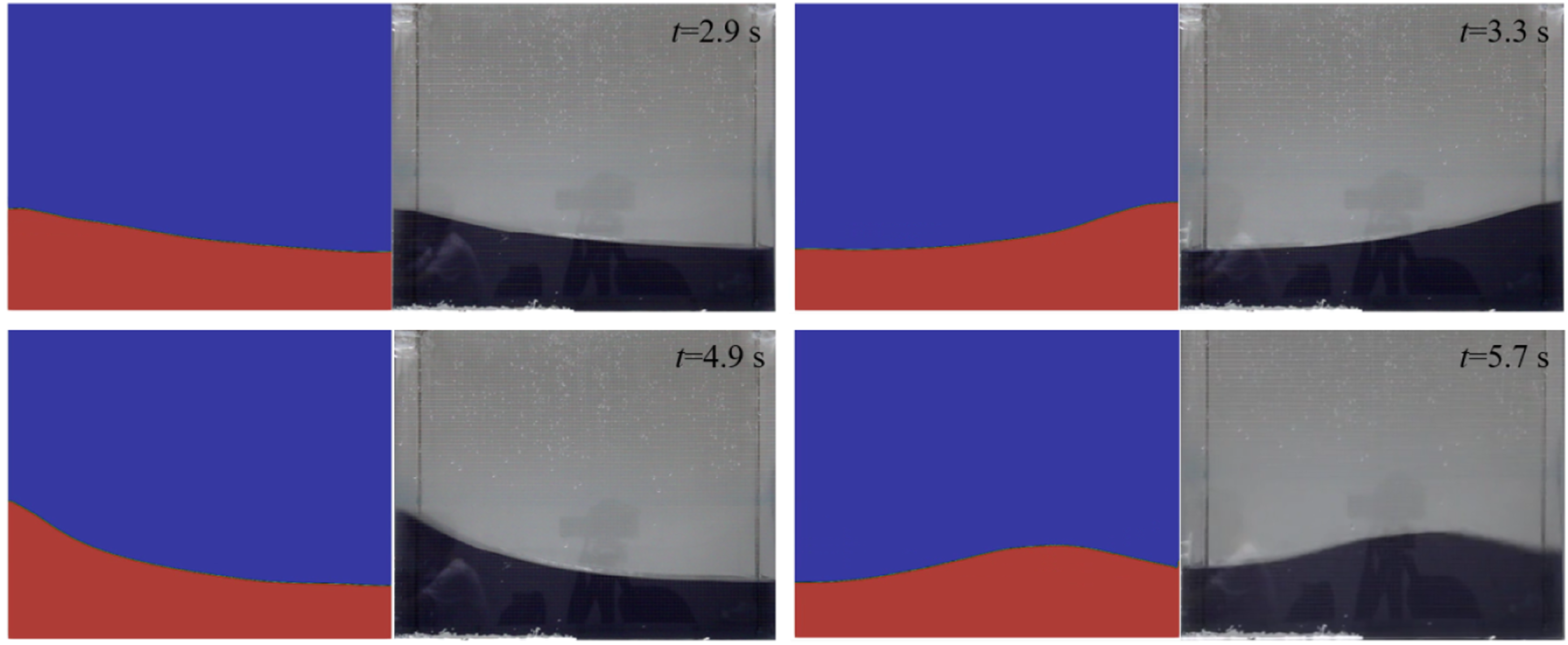
The numerical simulation in Figure 6 agrees with the test data, which shows that the numerical model established in this study can accurately predict the wall load of tank sloshing. The increase in simulation time and the measuring point height will affect the calculation accuracy caused by the accumulation of numerical errors and the severity of sloshing.
4. Results of TLD damping performance
4.1. Maximum displacement dynamic response
The control effect of different TLDs on the dynamic response of the whole coupling system at different installation positions can be obtained by numerical sweep tests. Figure 8 shows the maximum horizontal displacement of the coupled system, in which Figures 8(a)–(b) represents the third and first floor, respectively. The bare structure without TLD had been presented for comparison (black solid dotted line). It can be seen from Figure 8 that, at the first resonance frequency, TLD1 can suppress the horizontal vibration of the structure at any height. It is most preferable to place TLD1 on the third floor, where the maximum horizontal displacement reduction rate was 73.16%. For TLD1, the closer it was to the maximum displacement of the first mode shape, the more conducive it was to control the first mode shape because TLD1 itself was tuned to the first resonance frequency. However, the effect of TLD2 caused an increase of the structural response, especially when TLD2 was on the top. The negative effect increased the maximum displacement of the third floor by 54.55% compared with the case without damper. Maximum horizontal displacement of the coupled system at different locations. ((a) 3rd Floor; (b) 1st Floor).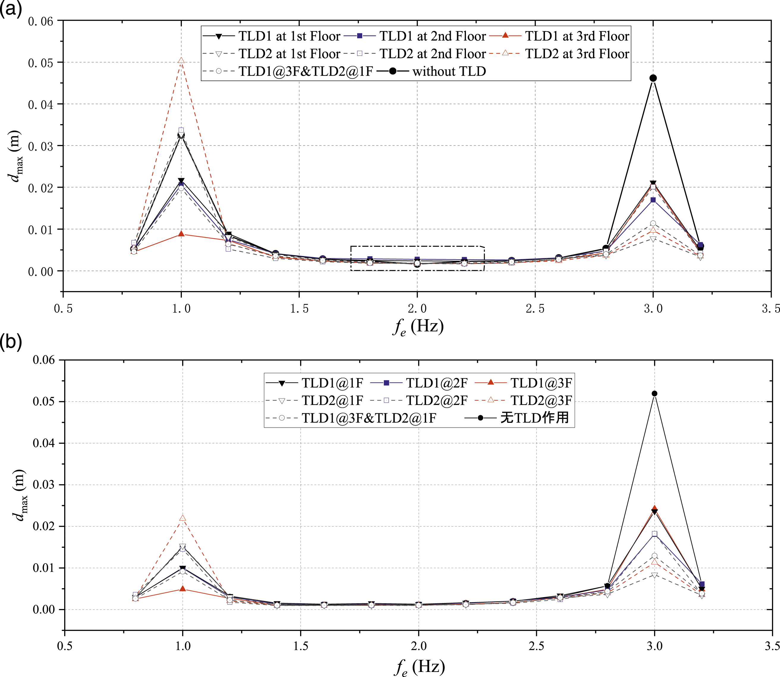
In the second mode, both TLD1 and TLD2 have reduced the maximum displacement. The control effect of TLD2 on the first floor was the best, which had an 83.19% decrease on the third floor, followed by TLD2 on the top platform. Combined with Figure 1, the conclusion could be summed that when the tuning ratio of TLD to structure is 1.0, TLD should be installed at the maximum displacement of the corresponding vibration mode of the structure. Notably, the E7 cases of the double TLD arrangement method have achieved an ideal control effect in the whole sweep range on the premise of keeping the total mass ratio 2%.
If the fundamental and multiple frequencies of the sloshing in TLD deviate from the structure's natural frequency, it may produce negative excitation. Locally enlarge the area in the box near TLD1 frequency doubling (1.7 to 2.3 Hz) in Figure 8(a), as shown in Figure 9, the dynamic response of the bare structure has a valley value at 2.0 Hz without the damper. However, the liquid sloshing in TLD provided the hydrodynamic force, especially for TLD1, it approached the frequency doubling position of the natural frequency because of the reciprocating sloshing impacts. The sloshing led to an increase in structural response, more significant than that of TLD2. It is recommended that the influence of frequency doubling on the coupling system should not be ignored in TLD design. Locally enlarged view of maximum displacements of the 3rd floor.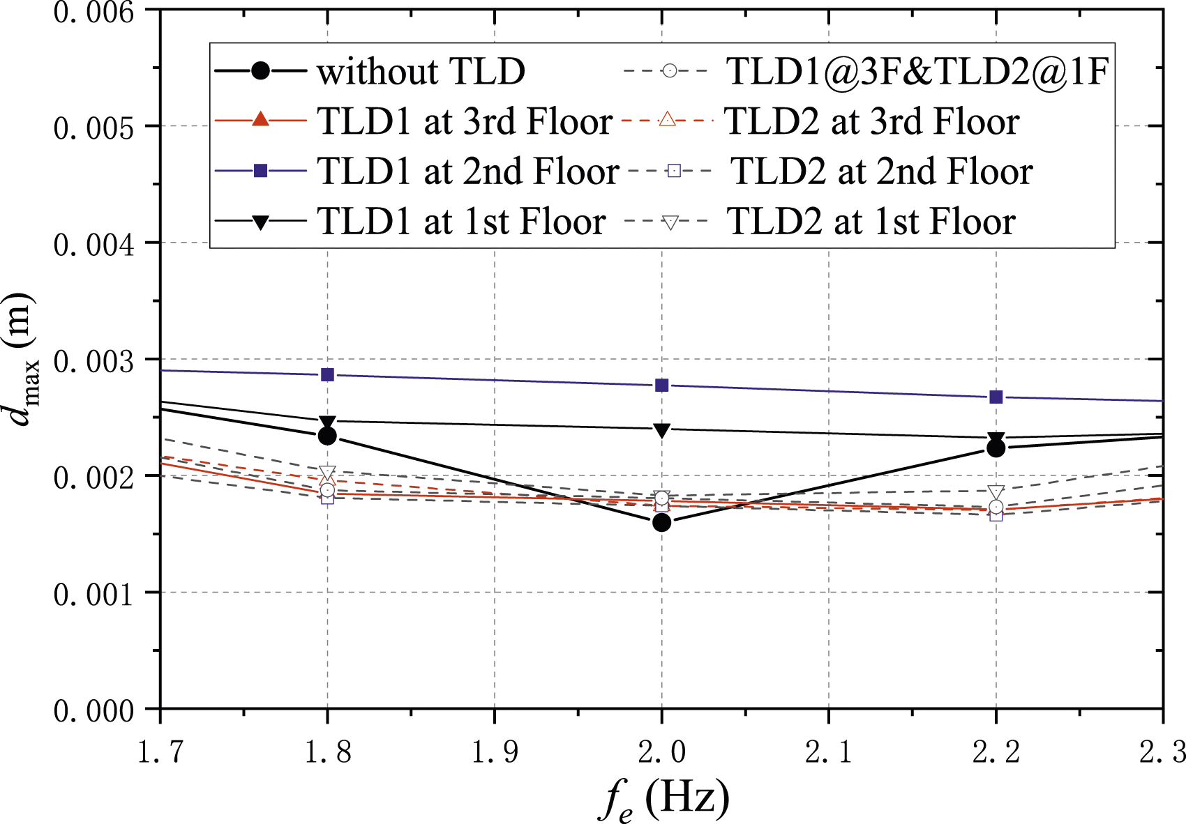
Figure 10 shows the displacement reduction ratio of the three floors where (a) and (b) represent the first and second resonance frequency, respectively. In Figure 10(a), it can be observed that in the E3 group, TLD1 installed on the third floor had reduced the dynamic response of the coupling system to the greatest extent. Its damping effect can reduce the maximum displacement of the first, second and third floor floors by 67.61%, 73.51% and 73.16%, respectively. When TLD1 was installed on the first and second floors, the reduction ratio decreased to 30%–40%, only half of the top floor. However, TLD2 not only had no pronounced control effect on the first resonance frequency when it was installed on the top floor but increased the maximum displacement of the three floors, which the reduction ratio was −44.50%, −50.74% and −54.55%, respectively. The displacement reduction ratio of the three floors. ((a) f
e
= 1.0 Hz; (b) f
e
= 3.0 Hz).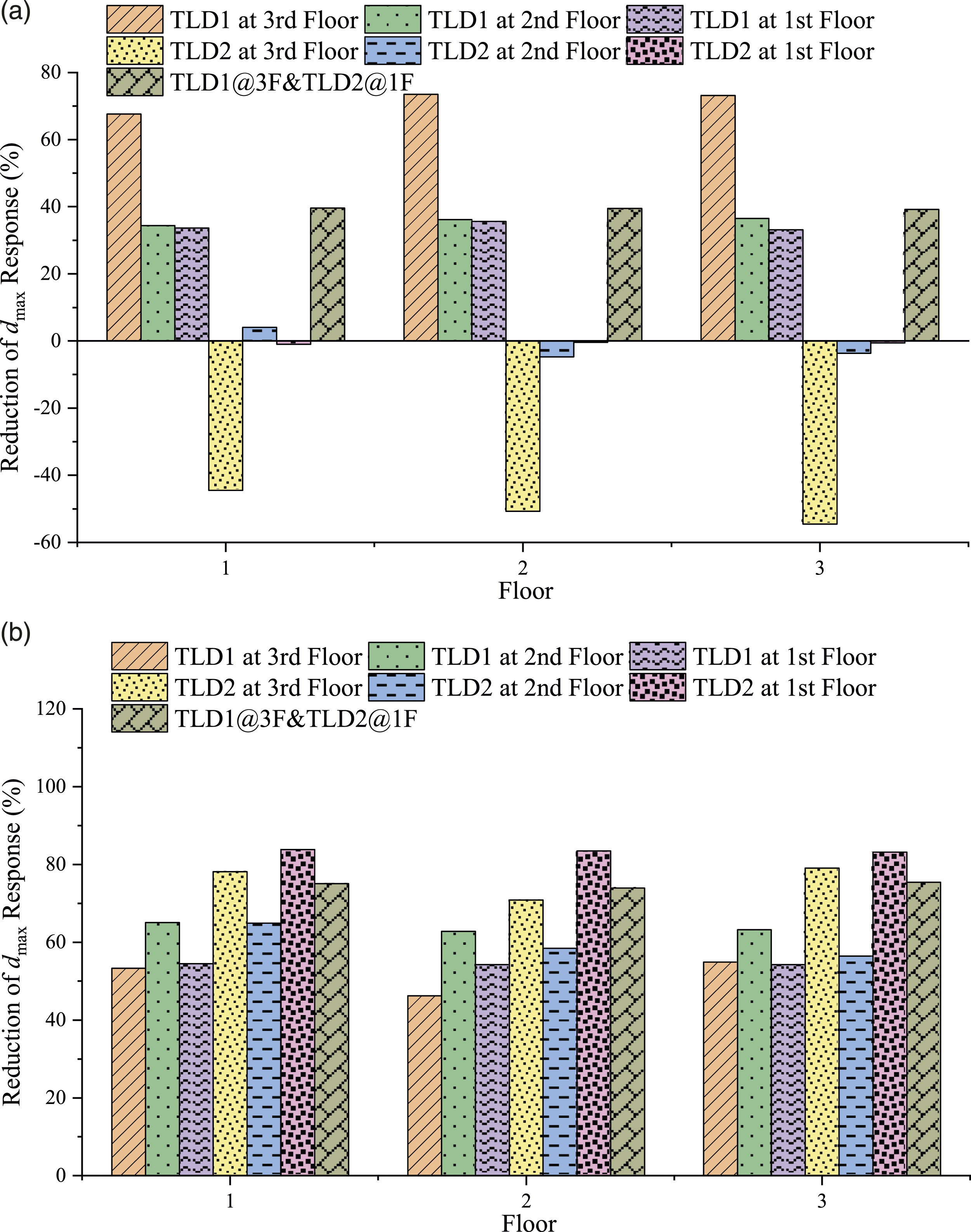
Figure 10(b) depicts the histogram of the maximum displacement reduction rate at the second resonance frequency of 3.0 Hz. It is suggested to install TLD2 on the first floor, which reduced the maximum displacement of the first, second and third floors by 83.83%, 83.48% and 83.19%, respectively. In group E7, the average reduction ratio of the mixed damper with TLD1 and TLD2 was 74.82%, which had only 8.68% different from the value of 83.50% in group E4.
4.2. Maximum acceleration dynamic response
Figure 11 shows the maximum horizontal acceleration of the coupled system at different locations, where (a) and (b) represents the maximum acceleration of the third and first floor, respectively. TLD2 has better damping performance than TLD1 in controlling the second resonance mode, which indicates the frequency ratio and installation position significantly affect the acceleration response of the structure-TLD system. It can be observed from Figure 11(a) that the acceleration of the top platform reaches the peak at the first two resonance frequencies when without any dampers, but in contrast, the first resonance peak is much less than that of the second. The maximum acceleration at the second resonance frequency decreased significantly with the TLD damping effect. In contrast, there had a negative effect on the acceleration response when TLD2 was installed on the roof at the first resonance frequency. In Figure 11(b), the acceleration of the first floor at the first resonant frequency is not sensitive to the TLD installation height, and the amplitude change is small. Maximum acceleration of the coupled system at different locations. ((a) 3rd Floor; (b) 1st Floor).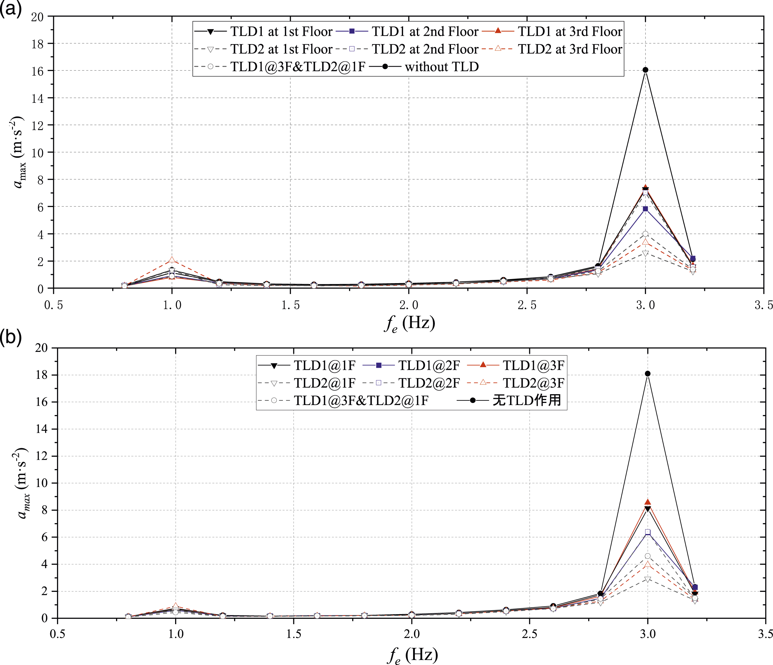
4.3. Motion analysis of the coupled system
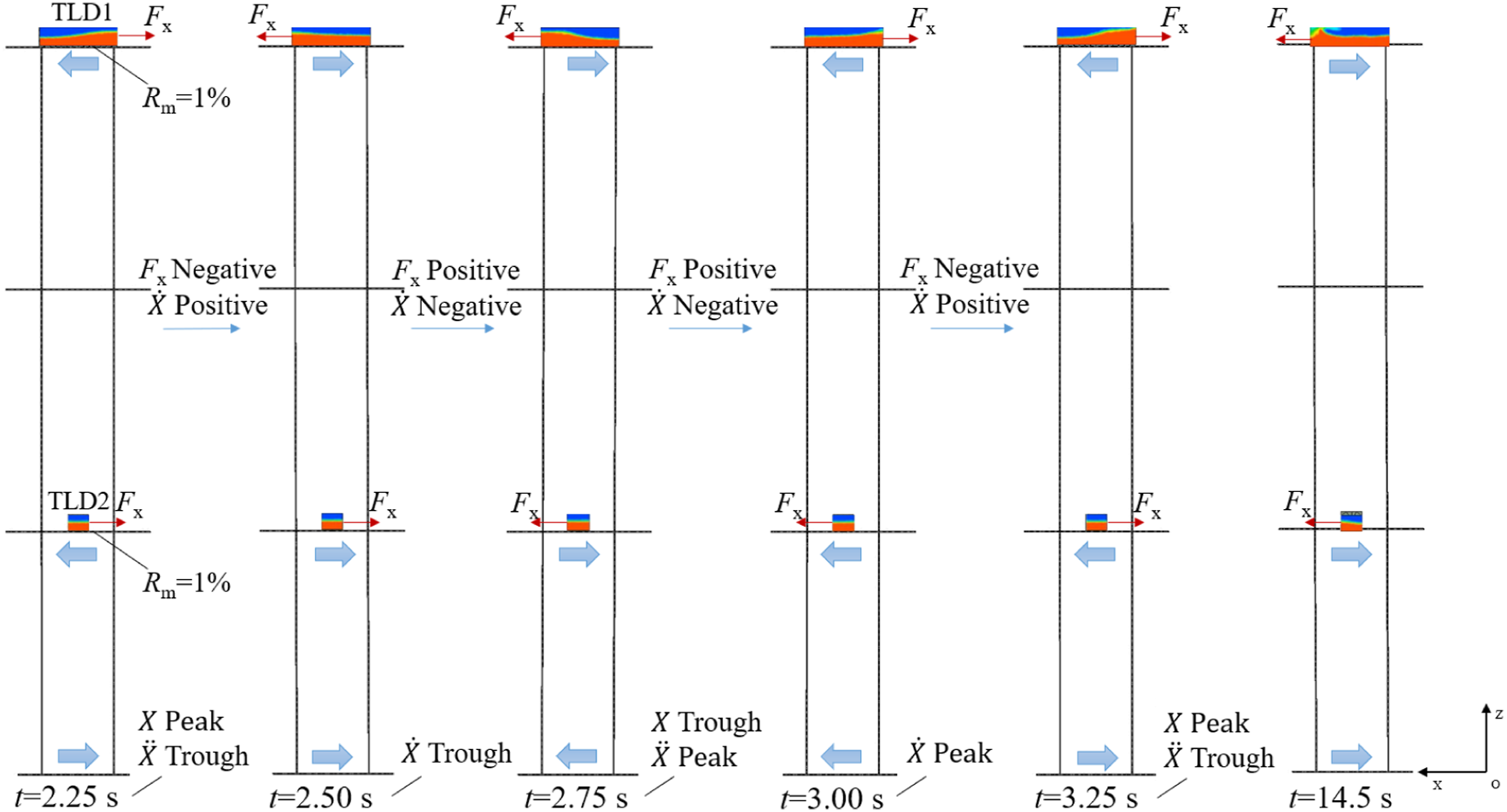
Figure 12 and Figure 13 presented the dynamic response process of the coupling system under two typical conditions, where t = 2.25∼3.25s is a complete motion period. When t = 2.25s the base moves to the leftmost side (displacement X reaches the peak, velocity Dynamic response process of the coupling system when TLD2 at 3rd floor. Dynamic response process of the coupling system when TLD1 at 3rd floor and TLD2 at 1st floor.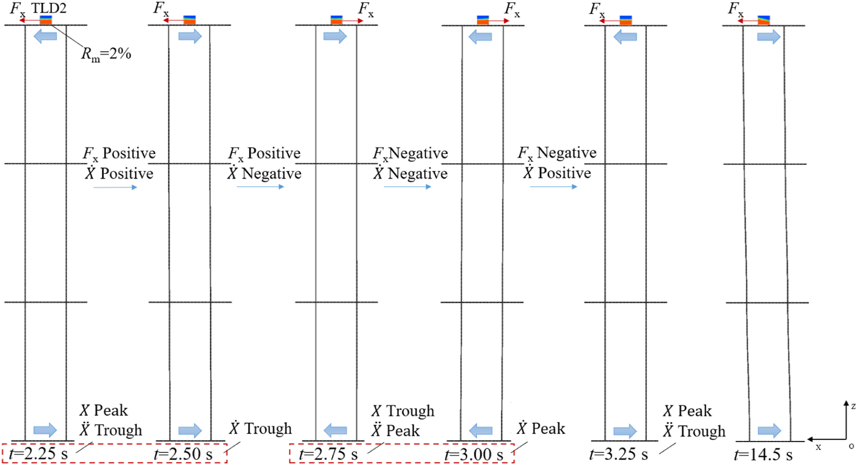
By keeping the 2% mass ratio constant, the combined damping system of TLD1 and TLD2 is more stable and effective. The TLD in the tuned state can assist in improving the damping performance of the non-tuned TLD, resulting in a higher percentage of positive work done by the damping force.
5. Energy dissipation characteristics of TLD
Figure 14 shows the hysteretic cycles developed by the hydrodynamic force versus the velocity. The nodes in the first and third quadrants of the coordinate system indicate that the velocity direction of the structure is the same as the hydrodynamic direction, and the hydrodynamic force does negative work. On the contrary, the nodes in the second and fourth quadrants mean that the hydrodynamic force does positive work. At these nodes, the hydrodynamic force dissipated the system energy in the form of damping. Therefore, in the cases where the excitation frequency is equal to the TLD, the velocity trajectory and hydrodynamic force present an ‘inclined column’ crossing the second and fourth quadrants in Figure 14. Most of the time, the sloshing force provided damping for the structure-TLD system. Combined with Figure 10, it can also be found that the maximum horizontal displacement of the cases corresponding to the ‘inclined cylindrical’ trajectory has been effectively reduced, while the control effect of the ‘elliptical’ trajectory has been reduced, and individual examples have adverse effects. The hysteretic cycles developed by the hydrodynamic force versus the velocity.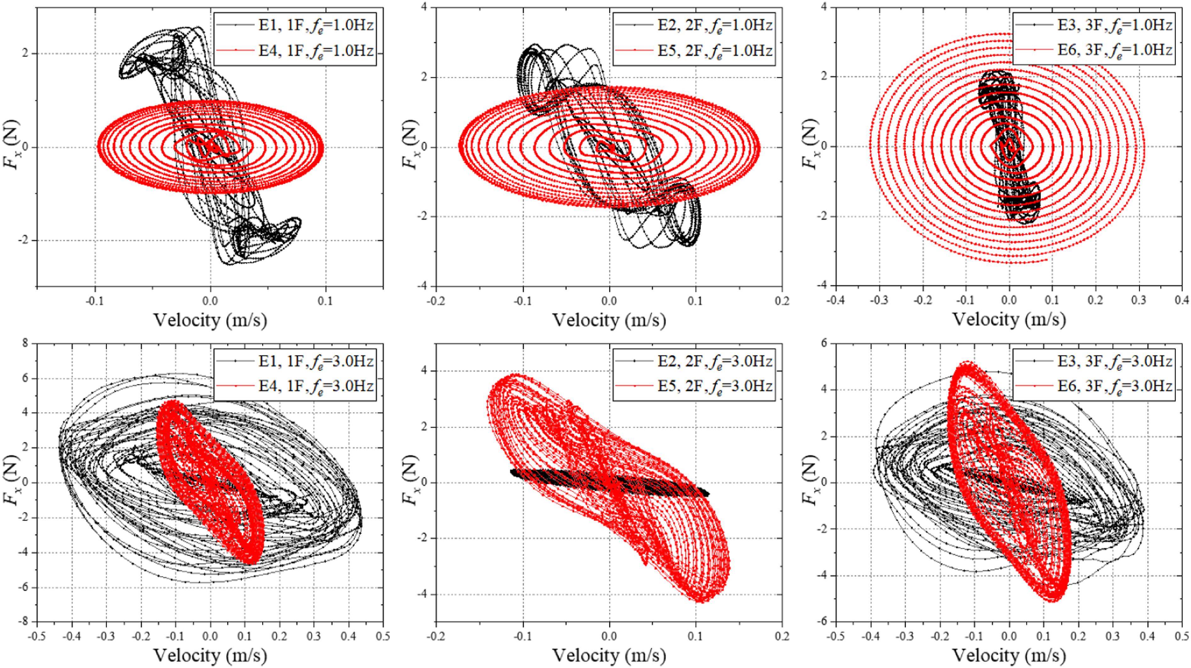
The TLD damping force energy dissipation can be obtained by integrating the time, Figure 15 shows the hydrodynamic work of the first resonance frequency. The red point indicates the positive work done by hydrodynamic forces in one step, and the blue indicates the negative work. It can be observed that the time nodes of positive work in E1 (see Figure 15(a)) are much greater than negative work, where the time proportion of doing positive work is 98.62%. At the first resonance frequency, the positive and negative work nodes of E4 (see Figure 15(b)) with poor control effects were evenly distributed on both sides of the X-axis. The positive work by hydrodynamic force accounted for about half of the total time, and the time phase of structural displacement and hydrodynamic force was π3/2. Hydrodynamic work of the first resonance frequency.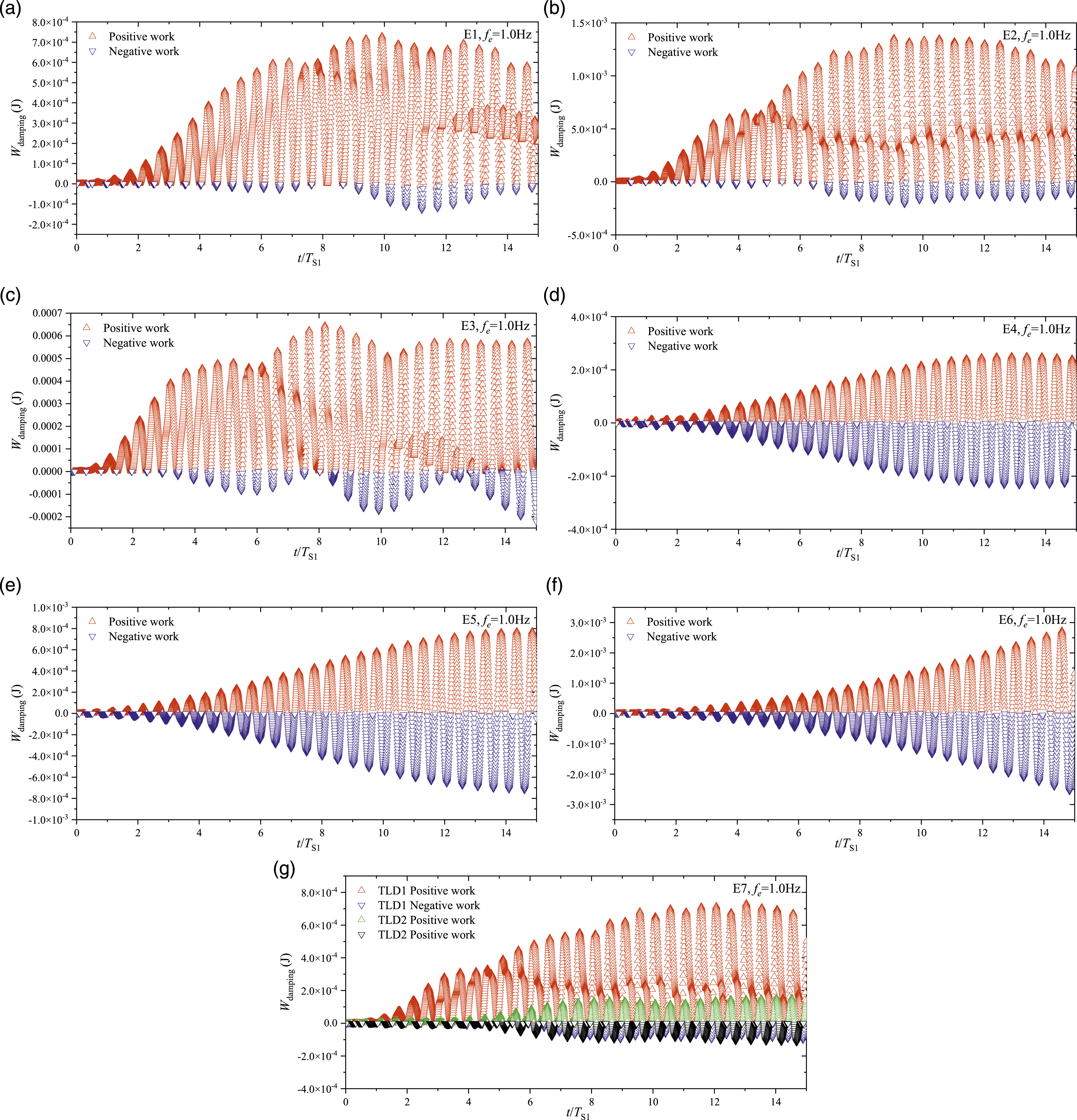
Work of the hydrodynamic force.
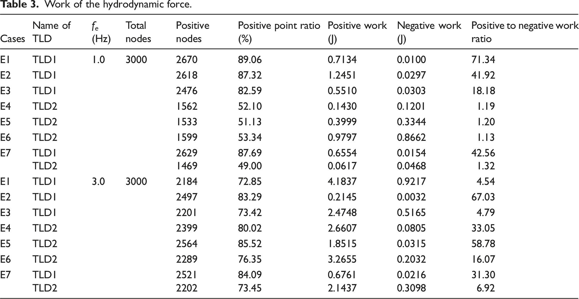
In Figure 16, the second resonance excitation f
e
= 3.0 Hz, the time for positive work time in 7 cases reaches at least 10.92s, accounting for 72.85% of the total time. Although the tuning ratio of TLD1 was 0.33 at the second resonance frequency, the values of positive work done by hydrodynamic force of cases E1, E2 and E3 account for 81.95%, 98.53% and 82.73, respectively. The results indicate that TLD1 has a wider vibration reduction frequency band. The positive work done by the TLD damping force is consistent with the maximum displacement reduction ratio in Figure 10. Hydrodynamic work of the second resonance frequency.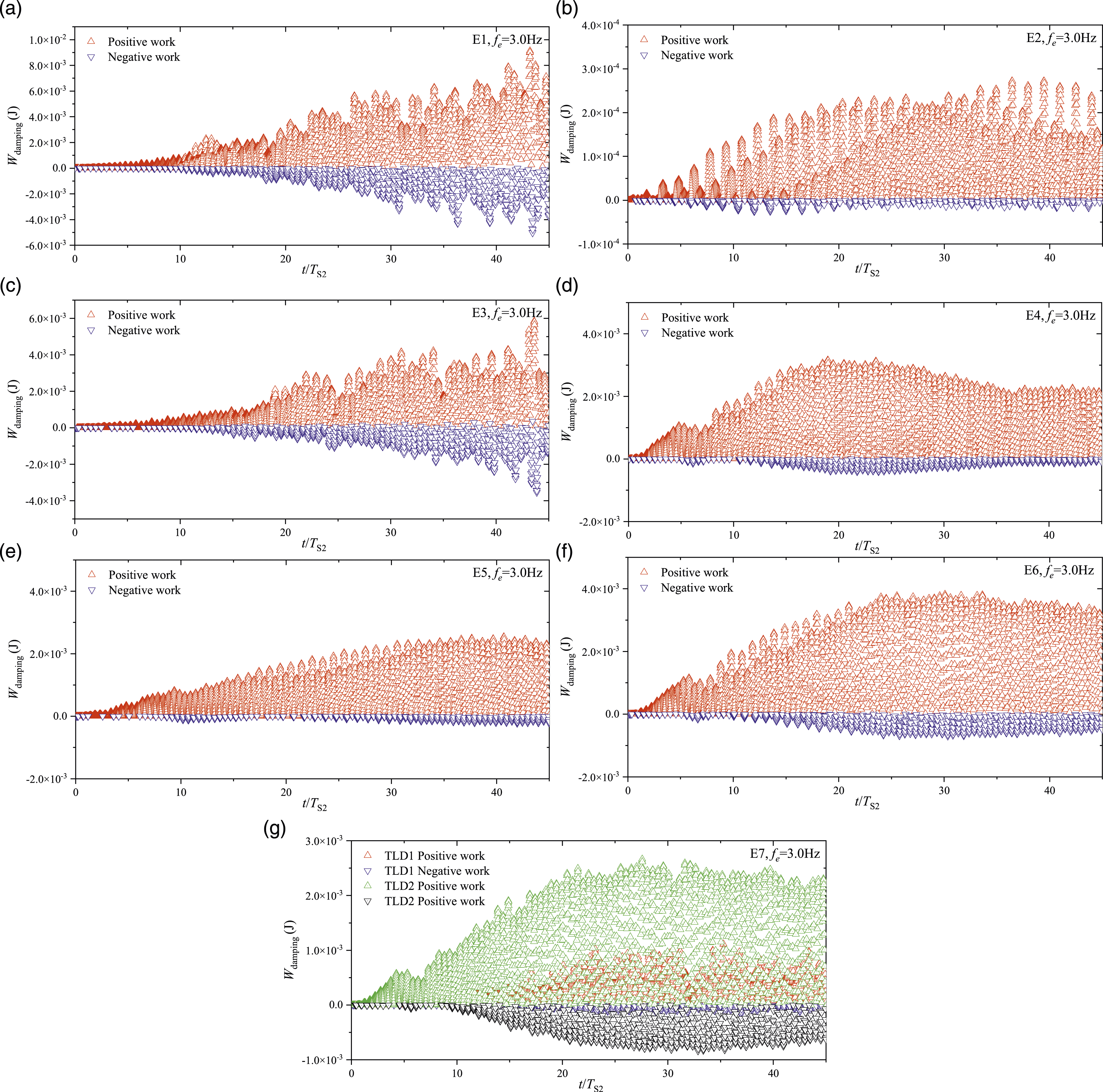
Figure 16 also shows that when the tuning ratio of TLD2 is adjusted to 1.0, the scatter distribution of E4, E5 and E6 are opposite to that in Figure 15, where most of the time points are doing positive work. This phenomenon is related to the hysteretic cycles in Figure 14. The ‘elliptical’ trajectory corresponds to the cases of equally positive and negative work time (Figures 15 (d)–(f)), and the ‘inclined column’ corresponds to the cases of good damping effect (Figures 16 (d)–(f)).
In the comparison of E7 groups, it can be observed that under the second resonance excitation, the damping energy dissipated by TLD2 is larger than TLD1, and the positive work of the former is 2.1437 J greater than that of the latter is 0.6761 J. Therefore, more system energy can be dissipated when the tuning ratio of TLD is 1.0. It should be mentioned that TLD1 tuned to the first resonant frequency can also increase the system damping at the second resonant frequency, while TLD2 increases the low-frequency structural displacement. Hydrodynamic work's positive and negative values can directly reflect the TLD damping characteristics. The optimal value of the time phase of structural motion displacement and hydrodynamic force is π/2. Keeping the mass ratio of 2% unchanged, the hybrid TLD composed of TLD1 and TLD2 achieved a good control effect simultaneously at the first two resonance frequencies.
6. Conclusions
This article investigated the damping performance of rectangular TLDs for numerically suppressing the vibration of a three-floor structure. The FVM/FEM method was employed to solve the fluid-structure coupling, and the maximum displacement of the three floors were obtained to estimate the TLD control effect. Based on the findings from the present study, the following conclusions were drawn: 1. By keeping the 2% mass ratio constant, the combined damping system of TLD1 and TLD2 is more stable and effective (TLD1 at 3rd floor and TLD2 at 1st floor). The TLD in the tuned state can assist in improving the damping performance of the non-tuned TLD, resulting in a higher percentage of positive work done by the damping force. 2. At the first resonance frequency, the time nodes of TLD1 positive work accounted for 94.79% to 98.62%, and the delay phase difference was π/2. Due to the detuning of TLD2, the positive work time of hydrodynamic force was reduced to nearly 50.0%, and the delay phase difference was π3/2. 3. In the study, the low mode TLD could realize the vibration control of the structural high mode, when the higher-order frequencies of the structure are multiples of the natural frequency of the TLD. If not, it will lead to negative excitation. A multi-TLD damping system is recommended, in which each damper is installed at the height of the maximum displacement of each structural mode.
The limitation of the current work is that for TLD to fully play its role, the arrangement of the resonance frequencies of each order of the structure must be in a multiple relationship, necessitating a reasonable design of the structure. Further studies on the current topic should target larger frequency bands for vibration reduction purposes. Elastic baffles, multi-layer liquids and porous media hold great potential for enhancing the energy dissipation characteristics and frequency modulation ability of TLD. Conducting relevant research is recommended.
Footnotes
Declaration of competing interests
The author(s) declared no potential conflicts of interest with respect to the research, authorship, and/or publication of this article.
Funding
The author(s) disclosed receipt of the following financial support for the research, authorship, and/or publication of this article: This study is supported by the National Natural Science Foundation of China (52101314, 52071163, 52301321), and the Natural Science Foundation of Jiangsu Province (BK20230669).