
Abstract
A solution for passive aeroelastic control is presented and tested experimentally on a bidimensional wing setup. The solution consists of a flap integrated in the wing which acts as a secondary mass damper and absorbs energy when aeroelastic instability is encountered. This device is passive, which makes it safe in emergency cases and adds little mass to the system in the fundamental case presented in this paper. If installed on actual aircraft wings, the flap-NES would not substitute but coexist with classic active control methods, adding virtually zero mass to the existing system. Using a flap placed in the airflow enables the control system to benefit from aerodynamic damping with a behavior dependent on wind speed. The device can either have a linear or nonlinear stiffness. It is shown that both options absorb energy from the main system, that is, the wing. The flap acts as a TMD (tuned mass damper) in the linear case and as an NES (nonlinear energy sink) in the nonlinear case. The nonlinear solution not only absorbs more energy at given wind speed but it also is a more suited solution as the damper follows the wind speed dependent frequencies due to its nonlinear feature. In this work, the flap-TMD and the flap-NES are tested experimentally on a bidimensional wing which presents classic flutter.
1. Introduction
Aeroelastic instabilities, such as flutter, are phenomena that limit flight speed of aircraft and can cause structural damage. Therefore, they have been widely researched both experimentally and numerically, such as in Collar (1978), Breitbach (1978), Thomas et al. (2012), and Fernandez-Escudero et al. (2019). Furthermore, many attempts have been made regarding different control techniques as presented in this section.
To increase aircraft flutter speed, and enlarge the flight envelope, active methods (energy inputted) are most common. A simple way of applying control forces is to use the aircraft’s control surfaces, which require fewer modifications of the structure as in Rao et al. (2006). Borglund and Kuttenkeuler (2002) achieved an increase in flutter speed of 50% on a rectangular wing. Yu and Hu (2012) performed an increase of 13.4% on an airfoil section, with both numerical and experimental analyses. Another approach that has been explored to apply the necessary control forces is the use of piezoelectric actuators, which can be used both in an active way in Asadi and Farsadi (2020) and in a passive way in Tsushima and Su (2017). Han et al. (2006) were able to increase the flutter speed of a swept-back cantilevered surface by 6–11%. Moses (1999) performed wind tunnel tests on a 1/6 scale model of a F-18 with tail buffeting and was able to decrease by about 60% the root mean square (RMS) amplitude of the vibrations using piezoelectric and control surfaces actuators. Morphing wing approaches are also an active approach to both enhancing wing performance that have been studied in Sun et al. (2021) and controlling aeroelastic phenomena in Ouyang et al. (2021) and Zhang et al. (2020, 2021). Although active methods are very effective, they have the important drawback of not being of any use in emergency cases (i.e., power shortage).
Regarding passive control, there are several solutions that do not rely on external energy. For instance, vibration control can be achieved via the choice of materials of the structure. Viscoelastic materials have proved to be very effective in vibration dissipation and an important advantage is that they are reasonably easy to install in existing structures, as in Cunha-Filho et al. (2016). However, the disadvantage is that their performance is highly affected by many factors, mainly temperature and vibration frequencies.
Another possibility for passive control is dynamic absorbers. This solution has been used both for vibration mitigation and for instability control. Depending on the characteristics of the stiffness and damping force added by the absorber, the properties and their applications vary. The simplest absorbers are tuned mass dampers (TMDs) which are a good option for vibration control in certain cases such as Jain et al. (2011) and are widely used in civil engineering. Carpineto et al. (2014) achieved structural vibration mitigation by using hysteretic TMDs. The classic linear TMD is simple and effective but it has the limitation of only being useful within a narrow frequency band due to being linear. In the case of an aeroelastic wing, the system’s natural frequencies change with the wind speed; therefore, TMDs are not an ideal solution. Also, for TMDs to be effective, significant mass must be added (10% the modal mass of the mode to be controlled) in Soto and Adeli (2013). Malher (2016) carried out experiments on a two degrees of freedom (2-DOF) aeroelastic apparatus using springs made of shape memory alloys to introduce hysteretic dissipation which proved to increase flutter speed and decrease limit cycle oscillation (LCO) amplitude. The energy dissipation rate was very high compared to other solutions; however, the effectiveness of this solution remains dependent on vibration frequency.
A solution which is more appropriate for systems with changing frequencies is the nonlinear tuned vibration absorber (NLTVA) studied in Habib and Kerschen (2015), Verstraelen et al. (2016), and Malher et al. (July 2017). Due to its nonlinear behavior, the NLTVA is effective for broad frequency band. However, it adds mass which is always a drawback in aeronautics. The nonlinear energy sink (NES) studied in Lee et al. (2007a, 2007b) is a particular type of NLTVA with a purely nonlinear stiffness and linear damping that presents high vibration absorption for a broadband frequency range and a very low added mass. For example, Pennisi et al. (2017) have developed a vibro-impact NES that adds only 1% of the system’s mass. The main characteristic of the NES is its cubic stiffness relationship. It is able to absorb energy from the main system and dissipate it via targeted energy transfers, also known as energy pumping, in Vakakis et al. (2008). The natural frequency of the NES is not unique but function of the vibration amplitude, so it is effective for broad frequency band.
NESs are already used in civil engineering and their main drawback is that their effectiveness is greatly dependent on proper parameter design. Current NES applications include both vibration mitigation and instability control, for example, shock isolation in Georgiades and Vakakis (2009), seismic vibration control in Nucera et al. (2008), energy harvesting in Ahmadabadi and Khadem (2014), suppression of the stick-slip phenomenon in machining in Gourc (2013), and other fluid structure interactions, such as vortex induced vibrations (VIVs), where a body is periodically excited by the vortex induced in the flow in Mehmood et al. (2014). Very recently, a vibro-impact NES has been used in galloping mitigation by Selwanis et al. (2021).
The proposed wing control system consists of a flap which can be configured as a flap-TMD or as a flap-NES depending on the linear or nonlinear nature of its stiffness, respectively; studied in Amar (2017). The idea of testing a nonlinear control device, efficient for broadband frequencies, is due to the fact that the frequencies of an aircraft wing vary throughout the flight due to, for example, fuel consumption or altitude. The flap is placed near the wing tip coexisting with, and not substituting, the already existent aircraft wing flaps used in active control as shown in Figure 1. The control device adds little mass to the system and is passive which makes it appropriate for emergency cases. Contrary to the previously described passive control systems, which rely on the addition of mass dampers inside the wing, the novelty of the solution lies in its inflow location. Since the flap is placed in the wind flow, it benefits from aerodynamic damping and wind speed dependent properties. This can be observed, for example, in Theodorsen’s aeroelastic model where each DOF’s speed is multiplied by the sum of the structural damping matrix and the aerodynamic damping matrix, the latter containing terms dependent on wind speed, in Grigorios (2017). The result is that the control solution itself is submitted to fluid structure interactions in a way which can enhance its control efficiency. Schema of the flap-NES concept in aircraft wing.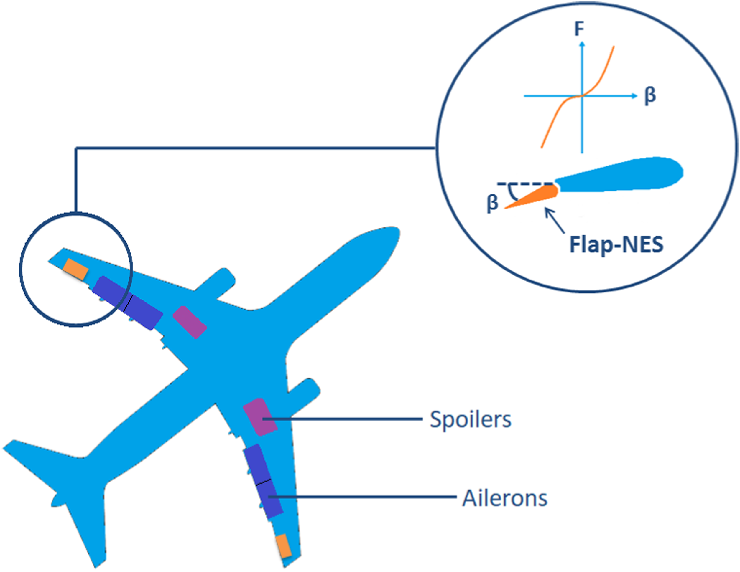
The effectiveness of flutter control using the proposed solution in a 2-DOF (degrees of freedom) bidimensional wing is presented in this work where the flap becomes a 3rd degree of freedom. Figure 2 presents the flap-NES integrated in wing and shows the cubic relationship of the control force (F) relative to the flap angle (β). The other 2-DOF are heave (h) and pitch (α). This work is considered as a first step toward the integration of the control device on a three-dimensional aircraft flexible wing. The structure is simplified in this way to carry out a first proof of concept of the control solution. Flap-NES concept in a bidimensional wing, showing the cubic relationship of the control force (F) relative to the flap angle (β).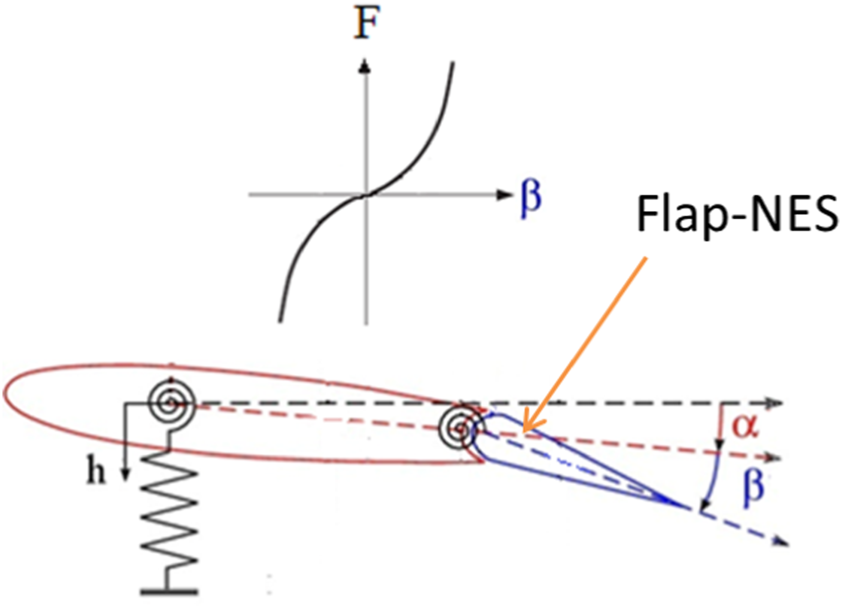
First, the experimental setup consisting of the bidimensional wing is described, as well as the instrumentation including the wind tunnel used. Next, the experimental protocol and the tests carried out are detailed, as well as the results and observations. The wing is tested without wind for structural characterization and with increasing wind speed to identify the flutter instability. The flap is blocked as the reference test case of the wing without control systems. The bidimensional wing is observed to present classic flutter by modal coalescence. Finally, the system is tested with the flap-TMD and with the flap-NES consecutively and proof of the instability control is achieved compared to the reference test case. The flap-TMD and the flap-NES control capacities are also compared.
2. Experimental setup
In this section, the experimental setup is presented including the wind tunnel where the tests were carried out and its characteristics, the bidimensional wing itself, and the mechanism which lies outside the wind tunnel and enables the movement of the wing. The flap-NES is presented and the way in which the cubic stiffness is generated is introduced.
2.1. Wind tunnel
The wind tunnel (Figure 3) used to carry out the tests is a low Reynolds, closed loop Prandtl Tunnel at atmospheric pressure. The tunnel has a total length of 2.4 m, a rectangular section of 1.2 x 0.8 m, and its contraction ratio is 9. The speed range of the airflow is up to 25 m/s, and the turbulence rate is below 0.1%. The experimental wind tunnel setup.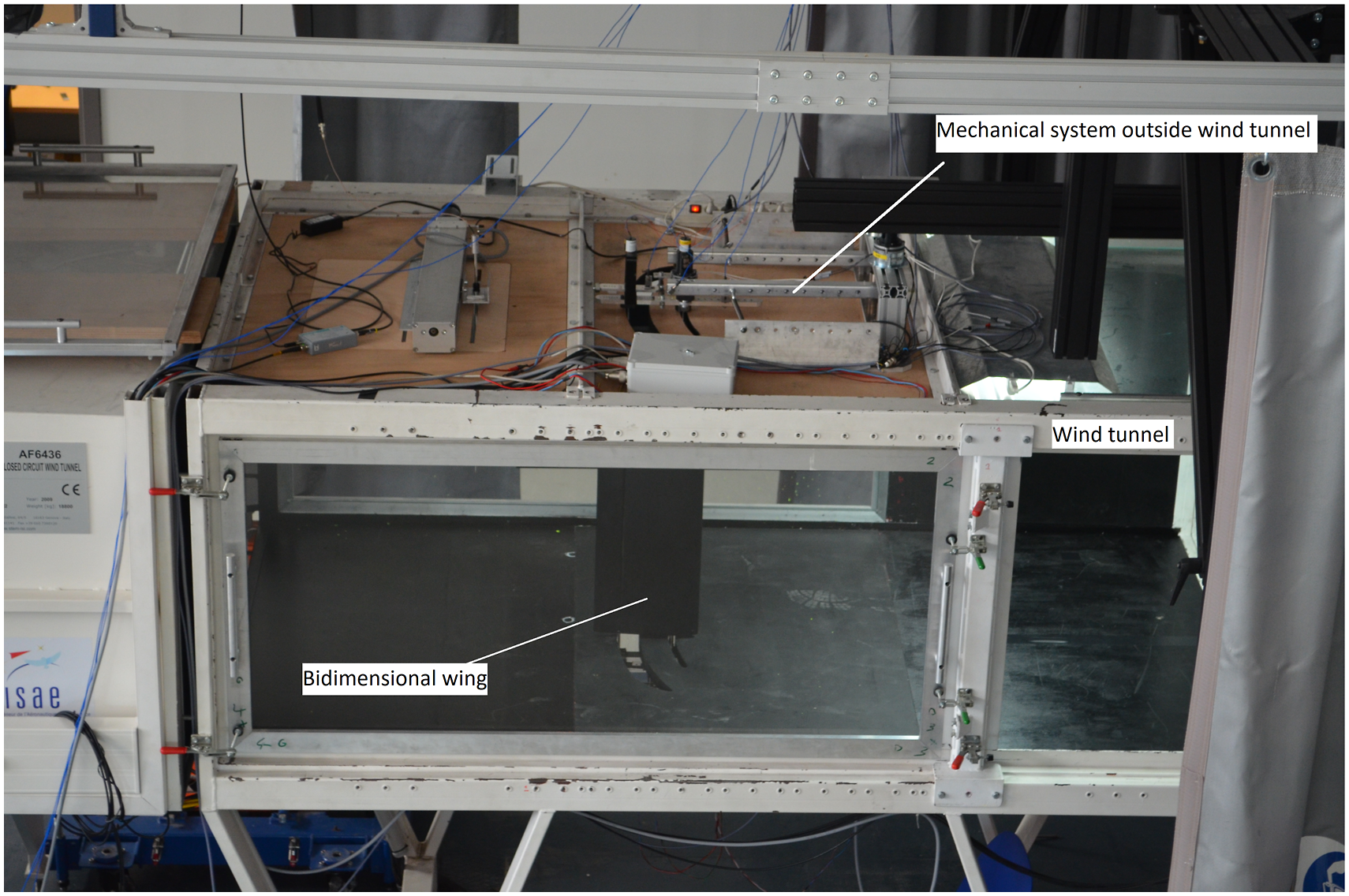
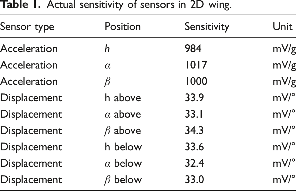
Two pitot tubes are used to measure wind speed in the tunnel, one on each side upstream of the wing, and they are connected to a static Kimo CP300 pressure probe. The measuring range of these probes is 0–50 m/s which is more than enough for the velocity range of the wind tunnel. The actual sensitivity of the pitot tubes is 0.015 m/s.
2.2. 2D wing setup
The setup consists of a rigid wing with a flap that spans the entire wingspan. The wing is placed vertically and is able to move on rails attached to the wing tunnel floor and ceiling to reproduce 2D wing aerodynamics. The wing has a chord of 0.25 m, a wingspan of 0.78 m, a total weight of 2.675 kg, and an inertia along the pitch axis of 4.13 × 10⁻² kg.m2. The profile chosen is a NACA 0012. The wing has an iron cylindrical spar, placed at 25% of the chord, which has a length of 1.1 m and a diameter of 0.012 m. Another iron spar with a length of 1.1 m, diameter of 0.006 m, a weight of 0.510 kg, and an inertia along the flap axis of rotation of 9.34 × 10⁻⁴ kg.m2 is placed at 75% of the chord and enables the rotation of the control between the flap and the wing to prevent dry friction between the two. Metal ribs, carbon stiffeners, a filler foam, and double-row ball bearings ensure the rigidity of the wing. A CAD view of the setup is shown in Figure 4. CAD view of the 2D wing setup.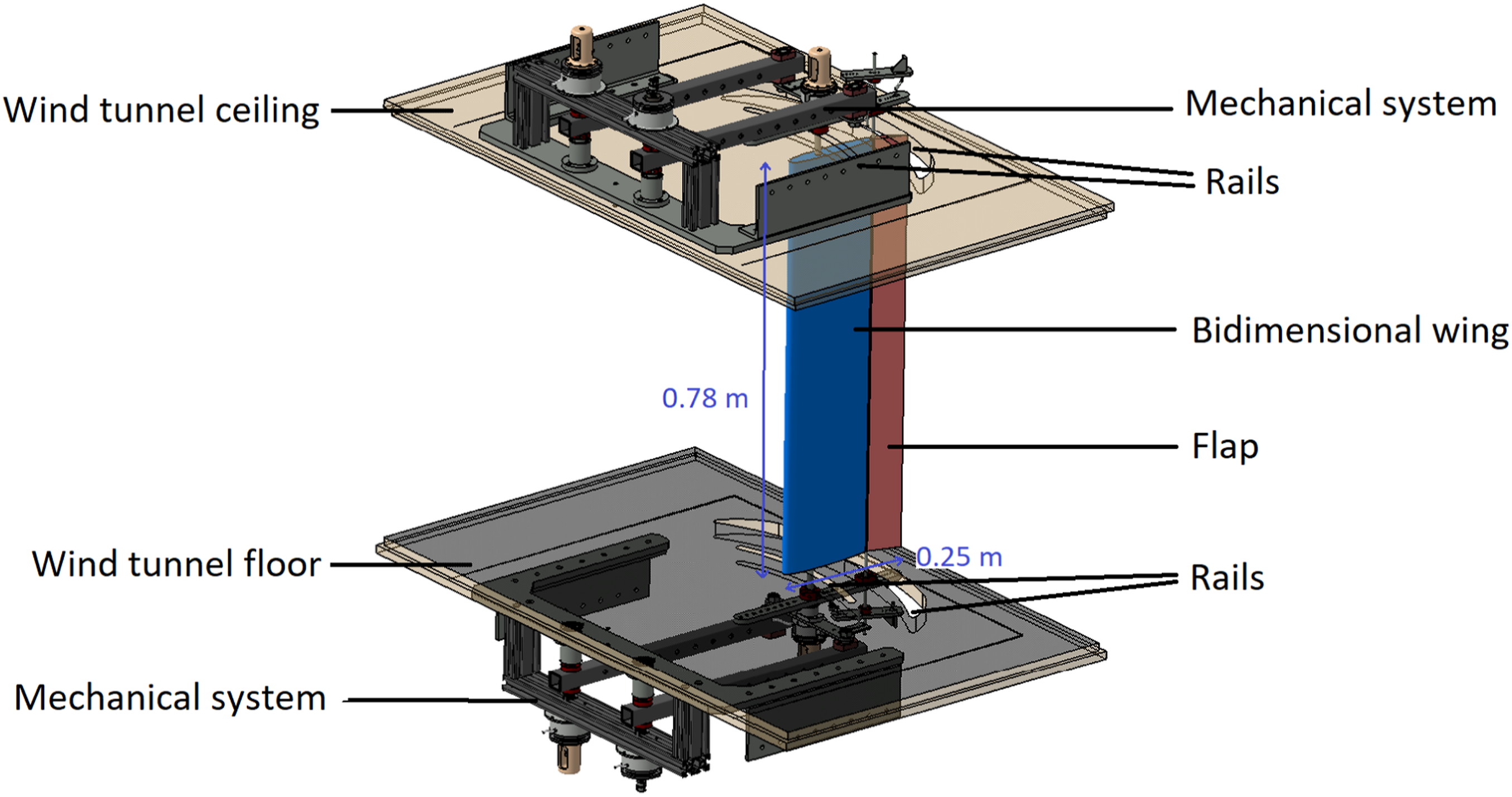
To enable the movement of the wing, there is a mechanical system placed above and below the wind tunnel so that it has no influence on the airflow. The mechanical system is divided into three subsystems, each one being responsible for one of the DOF (see Figure 5). Note that these subsystems come in mirror image pairs located at each end of the wing creating a vertically symmetrical setup. First, the heave (h) system is made up of three bars (green in Figure 5(b)) with the wing spar attached to the central bar. The torsional stiffness is varied by putting different springs between the bars and the fixed rigid frame, and by varying their location using 7 different hole pairs on the frame (visible on Figure 5(a)). Since the bars used for h are long (0.53 m), the movement is associated to a classical heave translation, although the actual movement is a rotation expressed as h(°). For the pitch (α) subsystem, one bar (blue) is connected to the spar and follows the rotation of the wing around the spar axis. Pitch stiffness is varied by changing the traction springs between the pitch bar and the heave system. Finally, to allow the flap rotation (β), one bar (red) is connected to the flap’s spar and follows the rotation of the flap. Mechanical system: (a) view from under the wind tunnel and (b) mechanical diagram: heave (in green), pitch (in blue), and flap (in red).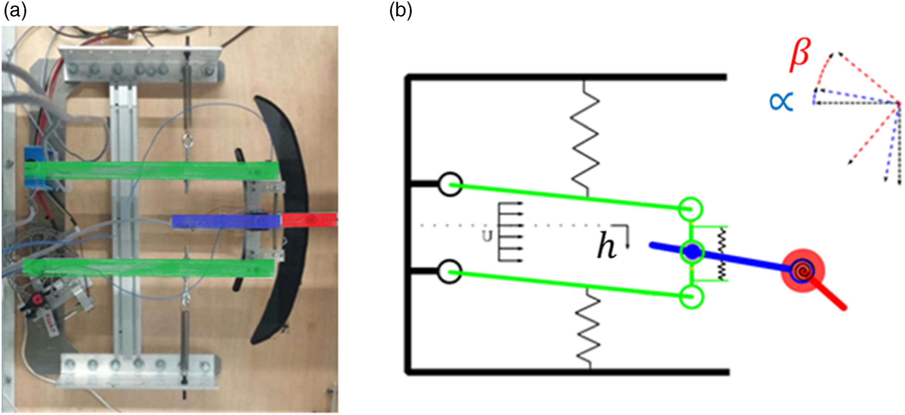
2.3. Flap
The stiffness of the flap is changed by modifying the spring configuration: • using torsional springs for a linear flap behavior (flap-TMD) as in Figure 5 and • using traction springs placed in parallel to have nonlinear stiffness when the flap is used as an NES. The Flap-NES cubic stiffness is obtained geometrically and detailed in the following section (see Figure 6). Flap-NES design: (a) CAD view and (b) schema.
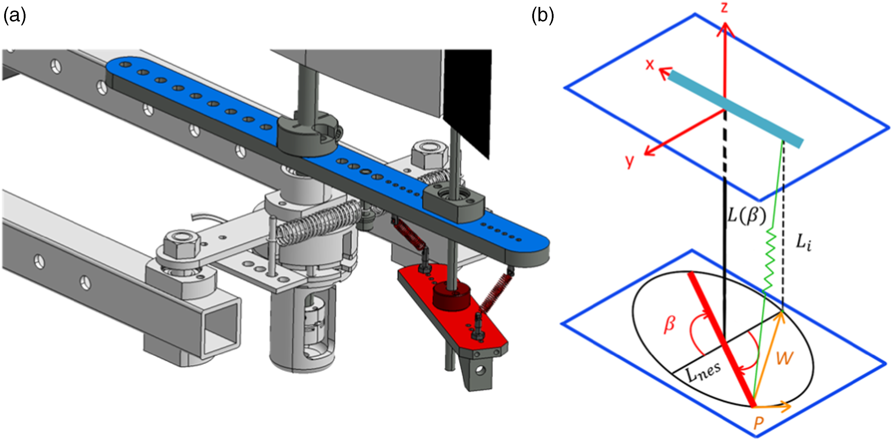
Figure 6(a) presents a close-up CAD view of the flap mechanical subsystem, initially presented in Figure 5(b), this time, equipped with a nonlinear stiffness obtained by parallel traction springs. Similarly to Figure 5, the pitch subsystem is identified in blue and the flap subsystem is identified in red. In Figure 6(b), when the angle of rotation (β) of the flap-NES is zero, the traction spring is parallel to the rotation axis and at a distance L
nes
from the axis. As the flap-NES rotates, the end of the traction spring remains still while the other end follows a plane circular trajectory of radius L
nes
around the rotation axis. The initial length of the spring is L
i
. The spring constant is K
u
, and its unstretched length is L
o
. The length of the spring at any given position β is L(β). The force F generated by the spring creates a moment, M, around the rotation axis. This moment M is found by projecting the force F onto the plane containing the flap subsystem (xy plane), giving force W, whose tangential component (P) multiplied by L
nes
gives the moment.
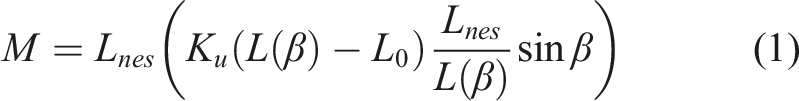

The cubic term then arises from the Taylor development of fourth order of this moment M, resulting in


The flap-TMD has the same general equation as the flap-NES, only this time k3 = 0, since its stiffness is purely linear.
2.4. Instrumentation
To start a test, an initial condition must be imposed on one or more DOF. This is done by a system of electromagnetic brakes that enables to fix the position of the wing and to release it at the start of a test. These brakes also have a security function and serve to stop the tests when required. The different DOF can also be fixed permanently with metal spars during the test to vary the number of DOF.
Actual sensitivity of sensors in 2D wing.
3. Results
This section contains the results of the experimental campaign which are divided into “zero wind speed tests” and “variable wind speed tests.” The first tests enable the wing structure to be characterized by identifying its natural frequencies, as well as to ensure the 2D behavior of the wing. The variable wind speed tests provide observations about the sub flutter regime and identification of the flutter speed, and allow observations about the post flutter speed regime. As mentioned earlier, all tests are carried out for the three configurations: 2-DOF (blocked flap), flap-TMD, and flap-NES.
3.1. Zero wind speed
First, each of the three wing’s DOF was characterized by obtaining their natural frequencies and stiffness in zero wind speed conditions. This was done by blocking two DOF and imposing an initial condition to the third DOF to obtain a 1-DOF damped free oscillating response. Three different initial conditions were imposed with the system’s breaks. The tests were repeated twice for each initial condition for h and for α. The response obtained for the different imposed initial conditions was the same; therefore, for the amplitudes tested, h and α are linear. The natural frequencies and the damping are obtained by curve fit using the damped harmonic oscillator equation: Sensor signal and fitted damped sinusoidal function comparison.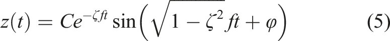
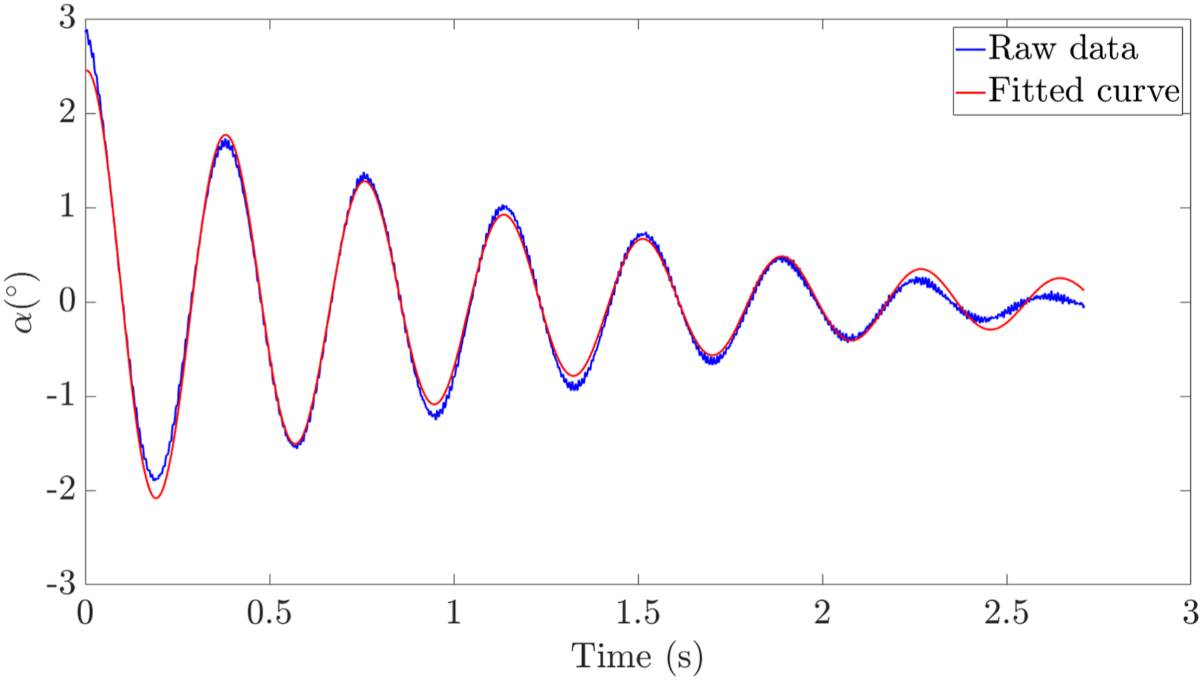
Natural frequencies and damping coefficient of each individual DOF.
Table 2 does not present values for β (linear or nonlinear), as the vibration is highly damped, therefore difficult to characterize. Additionally, the equation used for fitting, the damped harmonic oscillator equation, is not valid for the nonlinear β configuration and the initial condition is difficult to impose. Figure 8 shows the response of the linear and nonlinear β to an initial displacement manually imposed. Several flap-TMD and flap-NES configurations were tested experimentally but only two are shown in the current paper as they serve as a starting point to carry out an initial proof of concept of the control device. Response of the flap-TMD and flap-NES to a manually imposed initial displacement with zero wind speed.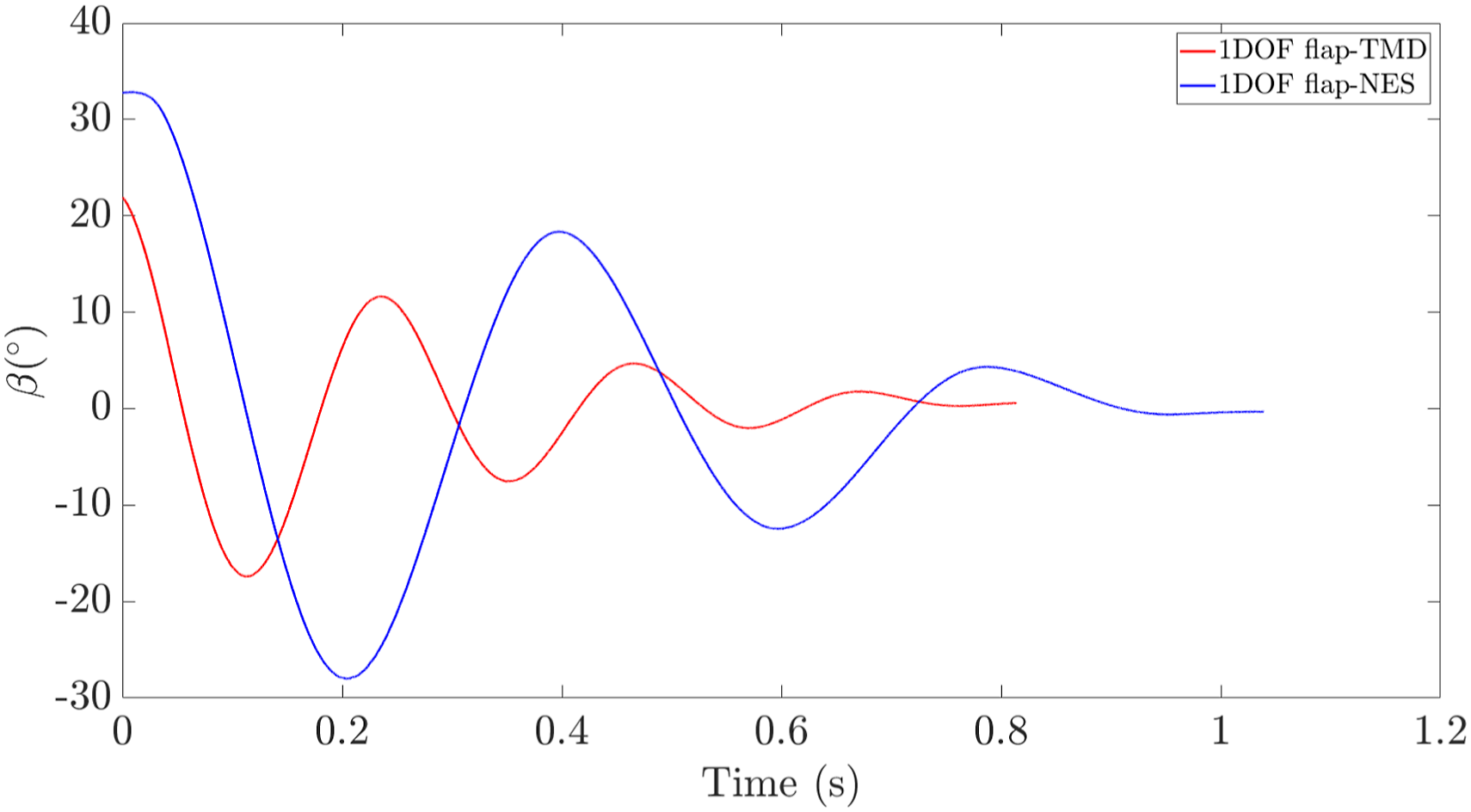
These 1-DOF tests are also used to compare the rotation measurements on top and beneath the wing that show the wing always to be in the same vertical plane with negligible (less than 5%) out of phase behavior from the upper and the lower wing. This is important as all 3D effects are to be avoided. With this verification done, from this point onwards, only the upper sensors’ measurements are analyzed.
3.2. Varying wind speed
Next, tests are carried out with varying wind speed, in the 2-DOF configuration (β, the flap, is blocked) and in the 3-DOF configurations which are the linear flap-TMD case and the nonlinear flap-NES. The first objective of these tests is, once the individual 1-DOF frequencies have been obtained, to determine if these frequencies vary with wind speed and if so, what is the interaction between each DOF for the different cases.
3.2.1. Flutter speed
Figure 9 presents the evolution of the frequency of each DOF for 2-DOF, flap-TMD, and flap-NES configurations, respectively. In these figures, it is observed that, as the wind speed increases, the oscillation frequencies for modes h and α coalesce. The coalescence means that the system is presenting classic flutter. In the configurations where the flap is unblocked, its frequency is considerably close to that of α and this can be observed to affect the appearance of the modal coalescence. Frequency evolution of h and α with wind speed. The red area contains the lowest wind speed at which h and α frequencies coalesce.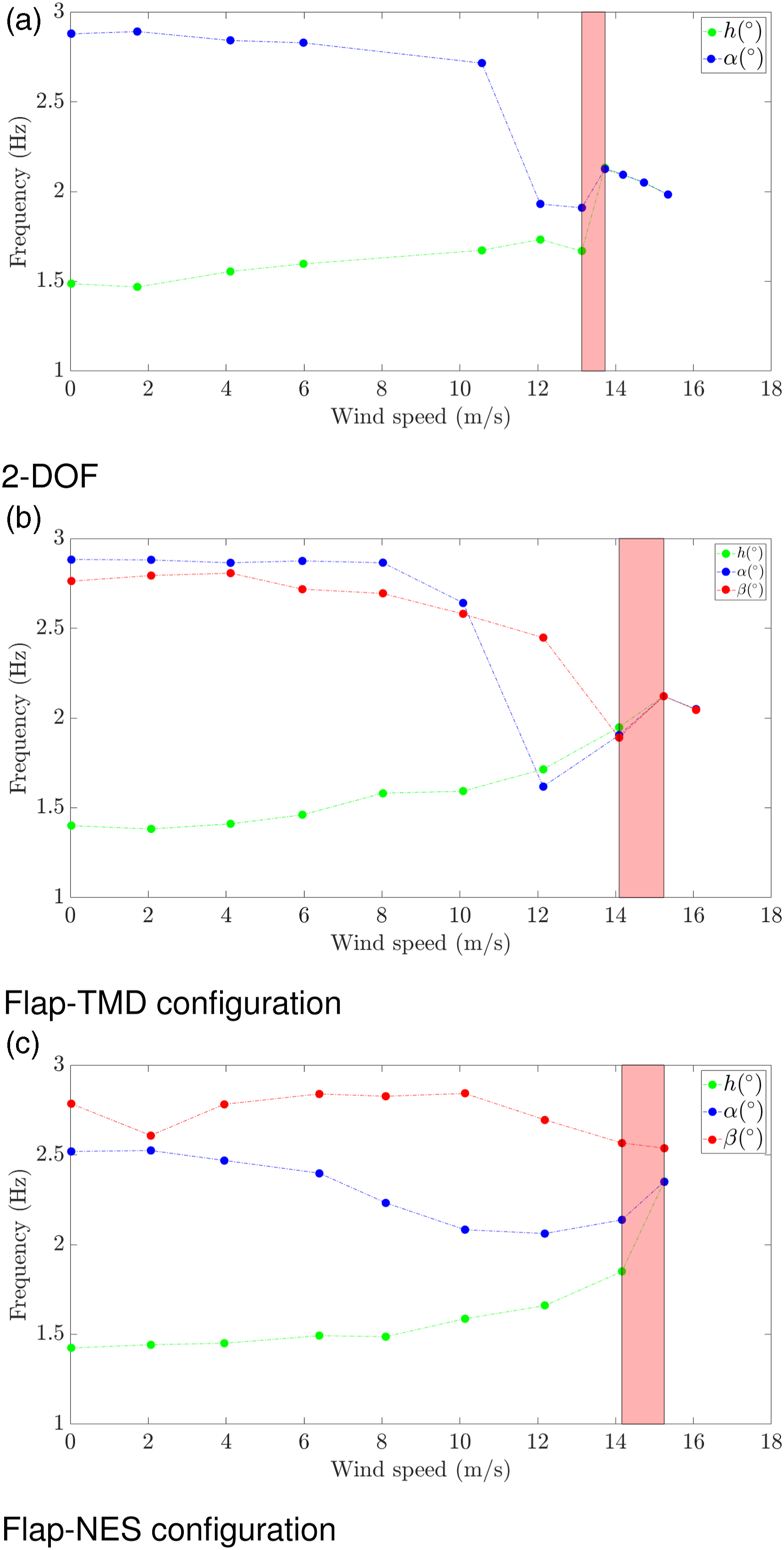
Range of wind speeds in which flutter speed (U F ) appears for different wing configurations.
Under this wind speed, oscillations are damped and above it limit cycle oscillations (LCOs) appear. LCOs are defined in Van Rooij et al. (2017) as “periodic solutions of non-linear aeroelastic systems. In contrast to linear flutter, the amplitude of an LCO does not grow unbounded, but remains constant due to the presence of a non-linearity of the involved forces.”
3.2.2. Post flutter
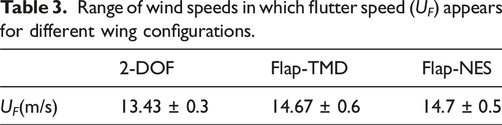
Looking at the post flutter regime, although modal coalescence is observed in all configurations (2-DOF, 3-DOF with flap-TMD and 3-DOF with flap-NES), the type of response is altered by the nonlinear character of the flap-NES. Figure 10 shows the time response, at a given post flutter wind speed, of each DOF at 2-DOF, flap-TMD, and flap-NES configurations, respectively. Figure 10(a) shows the constant amplitude LCO obtained with the flap-TMD, which is similar to LCO of the 2-DOF, whereas Figure 10(c) shows a highly modulated LCO response, an inherent characteristic of NES control (Lee et al., 2008). Time response in different configurations.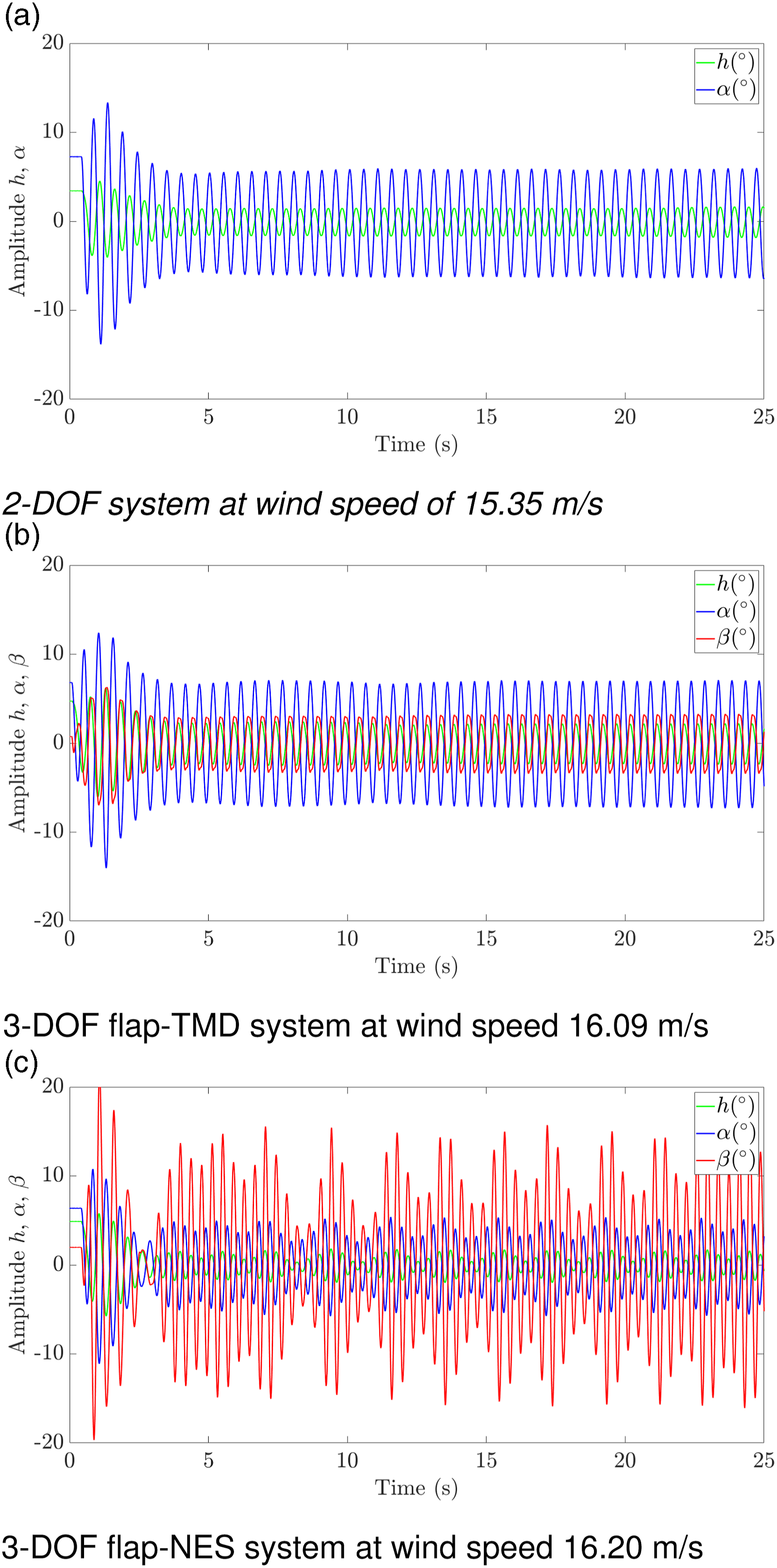
By obtaining the average peak amplitude of these LCOs (by using the last 10 amplitude positive peaks when the permanent regime is established) for each DOF and each configuration, Figure 11 is obtained. It shows the evolution of the LCO amplitudes with wind speed. The 3-DOF flap-NES case which presents a modulated response is given as a range of LCO peak amplitudes (see green area in the figures). It is observed that the flap-TMD reduces the vibration amplitude of the wing (by reducing both h and α) at any given post flutter wind speed. However, greater LCO reduction is obtained with the flap-NES, showing it to be a better solution for post flutter speed control. At high speed, the flap-NES changes the response from constant amplitude LCO to a modulated one which, most importantly, has lower average amplitude. Moreover, it is observed in Figures 11(a) and 11(b) that the 2-DOF configuration test had to be stopped at a lower wind speed than the other two configurations. This is due to safety reasons as the high amplitude LCO could cause structural damage to the wing. However, following the tendency displayed, the amplitude decrease caused by the control system continues to grow with increasing wind speed. Figure 11(c) shows an increase in the average flap-NES amplitude for all wind speeds, with respect to the average flap-TMD amplitude, meaning that a greater amount of energy was transferred from h and α to the flap. Average LCO amplitude. The green area for the 3-DOF flap-NES case represents a modulated response is given as a range of LCO peak amplitudes.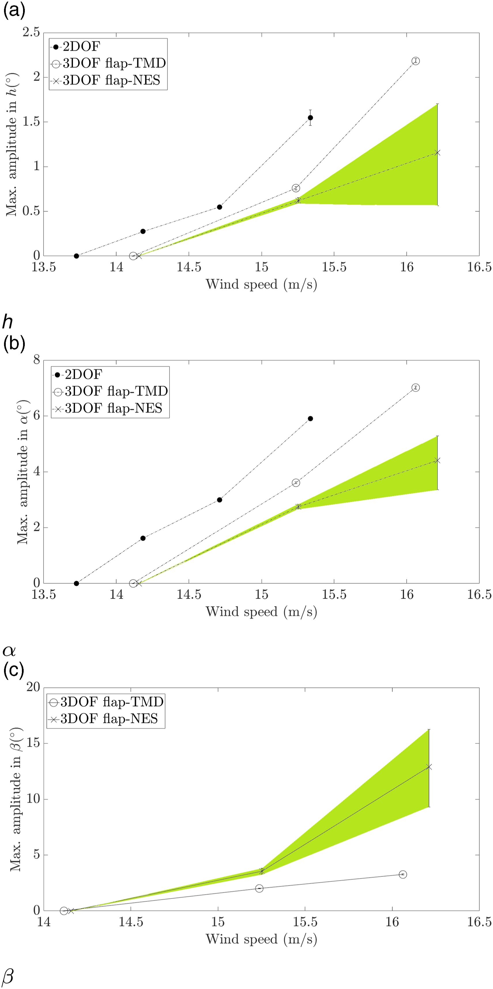
In addition, the energy transfer effect may be estimated by considering the total signal energy, obtained by adding the signal energies of h and α, and comparing the given values for each of the three configurations (2-DOF, flap-TMD, and flap-NES) at given wind speeds. This enables to carry out a comparison between the constant amplitude LCO (2-DOF and flap-TMD) and the modulated LCO (flap-NES). The signal energies are obtained by time integration of the square of each sensor time signal and, once added, are used to approximate the total energy of the system:
This estimation of the total energy is obtained at the maximum speed reached by the tests on the 2-DOF case of 15.35 m/s. For this given wind speed, the comparison of the different configurations shows up to 61% energy reduction using the flap-TMD, as compared to the 2-DOF case, and up to 79% energy reduction using the flap-NES, as compared to the 2-DOF case. The wind speed of the 2-DOF was not further increased since the motion’s amplitude became dangerous for the setup. Following the observed amplitude tendencies, it seems that the energy reduction using the flap-TMD or the flap-NES would be even larger at higher wind speeds.
4. Conclusions
In this work, a solution for passive flutter control is presented. It consists of integrating a passive control device that acts as a secondary mass damper and dissipates energy from the main system, when properly tuned. A flap-NES is created by introducing a flap with nonlinear stiffness. The flap-NES, which is also tested in its linear variant as a flap-TMD, is integrated in the bidimensional wing, therefore becoming its third degree of freedom. The paper describes an experimental proof of concept of the device on a bidimensional wing in a wind tunnel.
The setup is first characterized in zero wind speed conditions. Second, its dynamic response to varying wind speeds is obtained. The evolving response is identified as classic flutter caused by modal coalescence of the heave and pitch modes. The effectiveness of the flap-TMD and the flap-NES in passively controlling the flutter instability on the bidimensional wing in the wind tunnel is observed. The flutter speed is increased by 3%–16% respect to the baseline system by using both the flap-TMD and the flap-NES. Once in the post flutter regime, the LCO signal energy is reduced by up to 61% by the flap-TMD. The flap-NES showed greater control effectiveness in the post flutter regime with a LCO signal energy reduction of up to 79%, for the maximum wind speed tested for the blocked flap test.
Overall, this work presents and characterizes the effectiveness of a new solution for passive aeroelastic control which can be easily integrated in wings with little added mass and placed in the wind flow to benefit from wind speed dependent properties and additional aerodynamic damping. The capacity of the flap-NES of acting as a secondary oscillator and absorbing energy from the main structure in this context has been highlighted. In the case presented, high amplitude LCOs which could lead to eventual structural failure by fatigue are avoided with the flap-NES configuration.
Regarding the perspectives of this work, now that the proof of concept has been made on a bidimensional wing, the flap-NES will be tested experimentally for a three-dimensional wing. In parallel, analytical and numerical methods are developed to enable the design and optimization of this passive control solution.
Footnotes
Acknowledgments
The work greatly benefited from the expertise of the technical team and, in particular, Rémy Chanton, Henri Dedieu, Jean-Benoit Alibert, and Leonardo Sanches.
Declaration of conflicting interests
The author(s) declared no potential conflicts of interest with respect to the research, authorship, and/or publication of this article.
Funding
The author(s) disclosed receipt of the following financial support for the research, authorship, and/or publication of this article: This study has been funded by the Natural Sciences and Engineering Research Council of Canada, the Canada Research Chair program, and the French Initiative d’Excellence (IDEX) of Université de Toulouse.