
Abstract
As a key technique of vibration control, transfer path analysis (TPA) provides theoretical support for diagnosis, analysis, evaluation, and optimization of vibration in mechanical systems. The coupling phenomena often exists in the vibration transfer paths of complex mechanical systems, which makes most of the existing TPA methods unable to accurately analyze the transfer function of the coupled paths. The classical transfer path analysis (CTPA) is an effective method to solve the problem of path coupling, but it changes the inherent characteristics of the system, the results can not accurately reflect the vibration transfer characteristics of the system. In order to overcome the disadvantages of CTPA method, a decoupled transfer path analysis (DTPA) method is proposed in this paper, and the implementation process of this method is introduced by taking a hybrid mechanical system as an example. The results show that DTPA method can solve the path crosstalk problem and accurately calculate the transfer function of each path.
1. Introduction
The complex mechanical system contains many vibration transfer paths; the excitation source is transmitted to the position through multiple paths, causing the mechanical system vibration. The vibration transfer process of a mechanical system is shown in Figure 1, the transfer path consists of active end and passive end. Subsystem 1 contains the paths a-b and c-d, and Subsystem 2 contains two paths e-f and g-h. The excitation source f(s) acts at the point a of the active end, and is transferred to the passive end through four paths, a-b-e-f, a-b-g-h, a-c-d-e-f, and a-c-d-g-h, respectively, which causes the vibration of the passive end. Schematic diagram of vibration transfer process.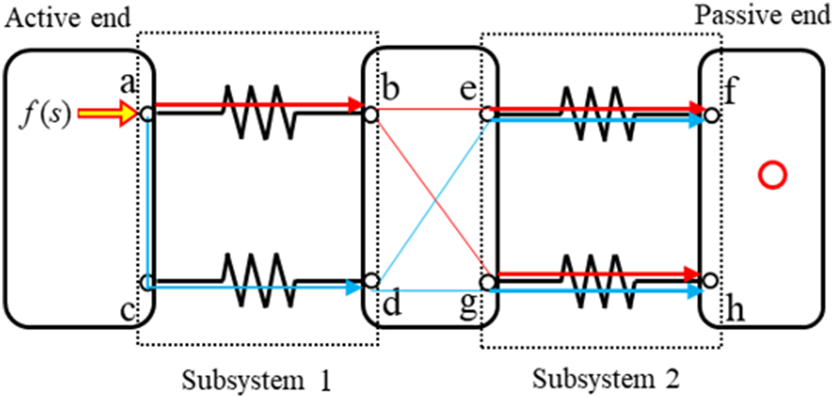
The factors that affect the vibration of the system mainly include the excitation source and the vibration transfer characteristics, and the excitation source is often difficult to change. Therefore, the vibration of mechanical systems is usually reduced by optimizing the vibration transfer characteristics (Ling et al., 2023; Lu et al., 2023). The vibration transfer function (VTF) is used to express the vibration transfer characteristic, which is determined by the inherent characteristics of the system. However, the path coupling can cause the distortion of the transfer function, which cannot reflect the vibration transfer characteristic of the single path, and mislead the choice of the optimal path (Mouzakis et al., 2019; Tatlow and Ballatore, 2017). TPA is an effective method to obtain the transfer function, and it is also the basis of diagnosis, analysis, and evaluation of vibration problems (Meggitt et al., 2021; Oktav et al., 2017; Zhu et al., 2018; Prenant et al., 2023). In order to accurately obtain the transfer function of each path in a complex system, the path coupling problem should be fully considered. The TPA method can transform a complex mechanical system into a discrete chain structure and analyze the main path of vibration transfer.
Transfer path analysis methods include classical transfer path analysis (CTPA), operational transfer path analysis (OTPA), operational-X transfer path analysis (OPAX), hybrid transfer path analysis (HTPA), and multistage transfer path analysis (MTPA). In the CTPA method, the complex system can be simplified into a “source-path-response” model, and the system is divided into passive side and active side by dismantling method, and the excitation is applied to the active side as input, the response signal is collected on the passive side as output, the system transfer function is calculated according to the input signal and the output signal. Although the CTPA method is simple, the boundary conditions of the system are changed (van der Seijs et al., 2016; Sakhaei and Durali, 2014).
OTPA method is suitable for multi-input and multi-output models, and the transfer function matrix is used to represent each path. The method is simple and efficient, but the coupling between paths seriously affects the analysis accuracy (Sitter et al., 2010; Tan et al., 2018). OPAX is proposed on the basis of CTPA method and OTPA method, which improves the calculation precision and analysis efficiency of transfer function by adding reference points. However, for complex mechanical systems, OPAX parametric modeling is difficult, which limits the application of this method (Janssens et al., 2011; Wang et al., 2019). HTPA is to analyze the vibration transfer function by using test and simulation methods. Although this method is simple and easy to operate, HTPA requires high accuracy of simulation model and does not solve the coupling problem between paths (Liu et al., 2021). MTPA method does not need to separate passive side and active side, and uses the same test method as CTPA to obtain the transfer function of each subsystem and analyze the contribution degree of each path. Due to the coupling between the subsystems, the result of analysis is distortion (Mashayekhi and Behdinan, 2017; Acri et al., 2016).
Because TPA is an effective method for vibration analysis, the improvement of TPA method is still a hot topic (Ginés et al., 2021; Kim et al., 2017). In order to overcome the defects of the existing TPA method, solve the coupling problem of the transfer paths and improve the analysis precision of the transfer function of the complex mechanical system. A decoupled transfer path analysis (DTPA) method is proposed based on CTPA method in this paper. The method can realize the decoupling of the transfer paths, avoid the path crosstalk problem, and calculate the transfer functions of each path accurately. And the main contents are as follows: 1. The DTPA method is proposed based on the CTPA method and the DTPA analysis model is built. 2. The implementation process of DTPA method is summarized, and the matching method of auxiliary elastic support stiffness is introduced. 3. The difference between the results of CTPA method and DTPA method is analyzed, and the correctness of DTPA method is verified.
2. Theoretical aspects
2.1. DTPA method
Figure 2 shows a schematic diagram of the parallel mechanical system. As shown in Figure 1(a), elastic element k1 and damping element c1 form the No. 1 transfer path, while elastic element k2 and damping element c2 form the No. 2 transfer path, and the two systems are in parallel. A unit pulse excitation is applied at O1, and the vibration signal is transmitted along two paths to O2 position. The equivalent transfer function is equal to the sum of transfer functions of each subsystem. Parallel mechanical system. (a) Mechanical model of parallel system and (b) Force analysis.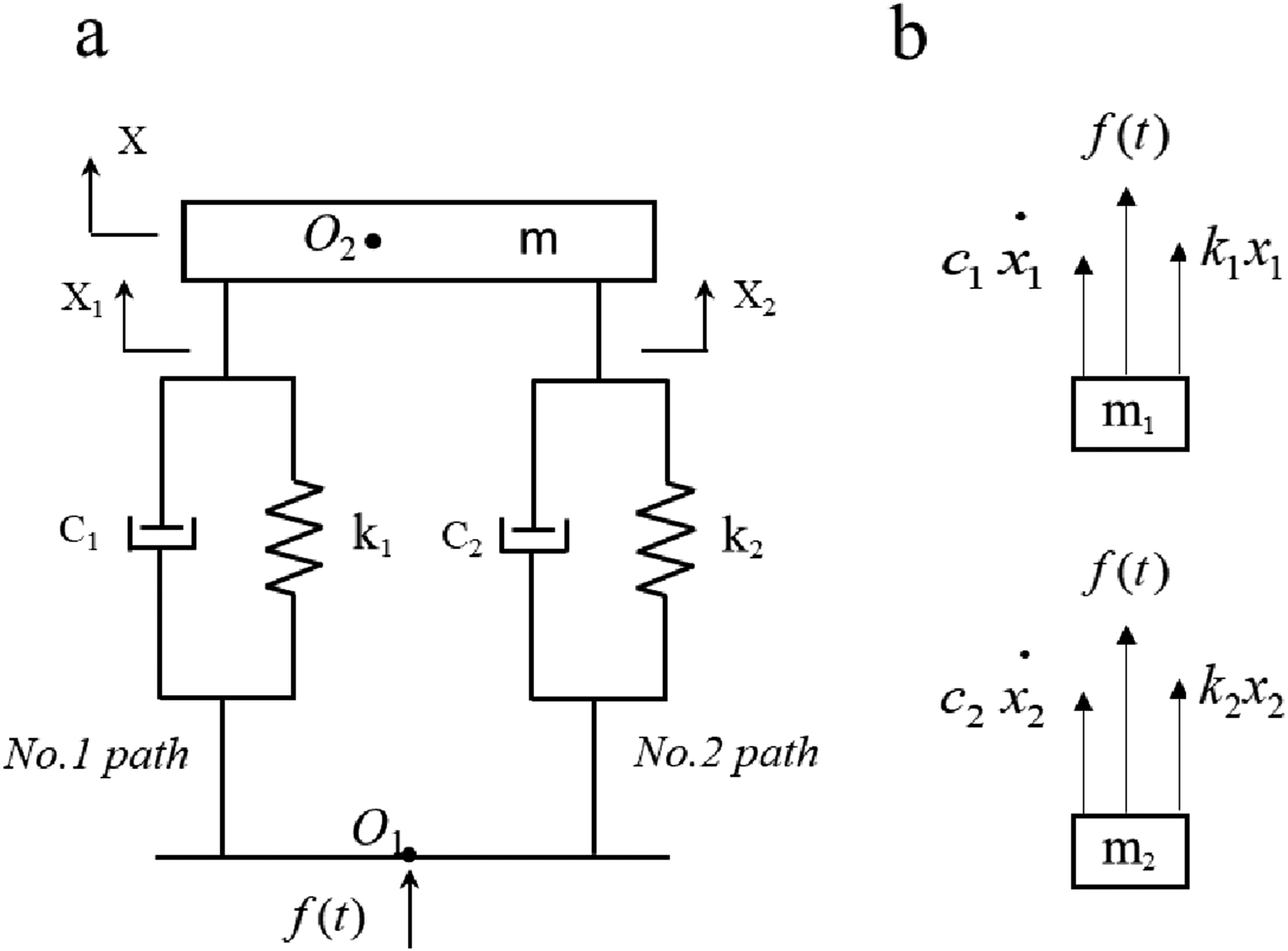
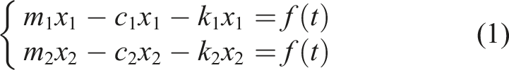
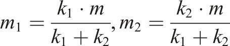
Under the action of external input f(t), the mass m is only translational. At the static equilibrium position, spring k1 loads quality m1, spring k2 loads quality m2, and the sum of m1 and m2 is m, as shown in Figure 1(b). The displacement (x1,x2) is taken as generalized coordinates, and the vibration differential equation is
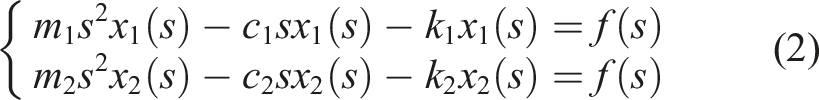
The equivalent transfer functions of path 1, path 2, and parallel system are respectively
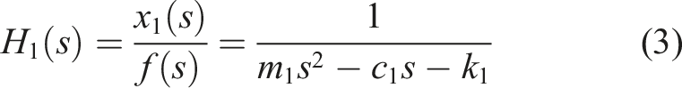
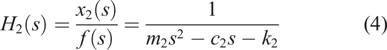
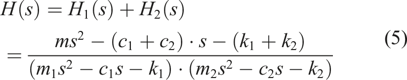
Equation (3) and equation (4) show that the transfer functions of path 1 and path 2 depend on the stiffness, damping, and mass of the respective systems. Equation (5) shows that the transfer function of the parallel mechanical system is determined by the transfer characteristics of path 1 and path 2, and the two paths are coupled with each other. Figure 3 shows a schematic diagram of path coupling analysis for a parallel system. Schematic diagram of path coupling analysis.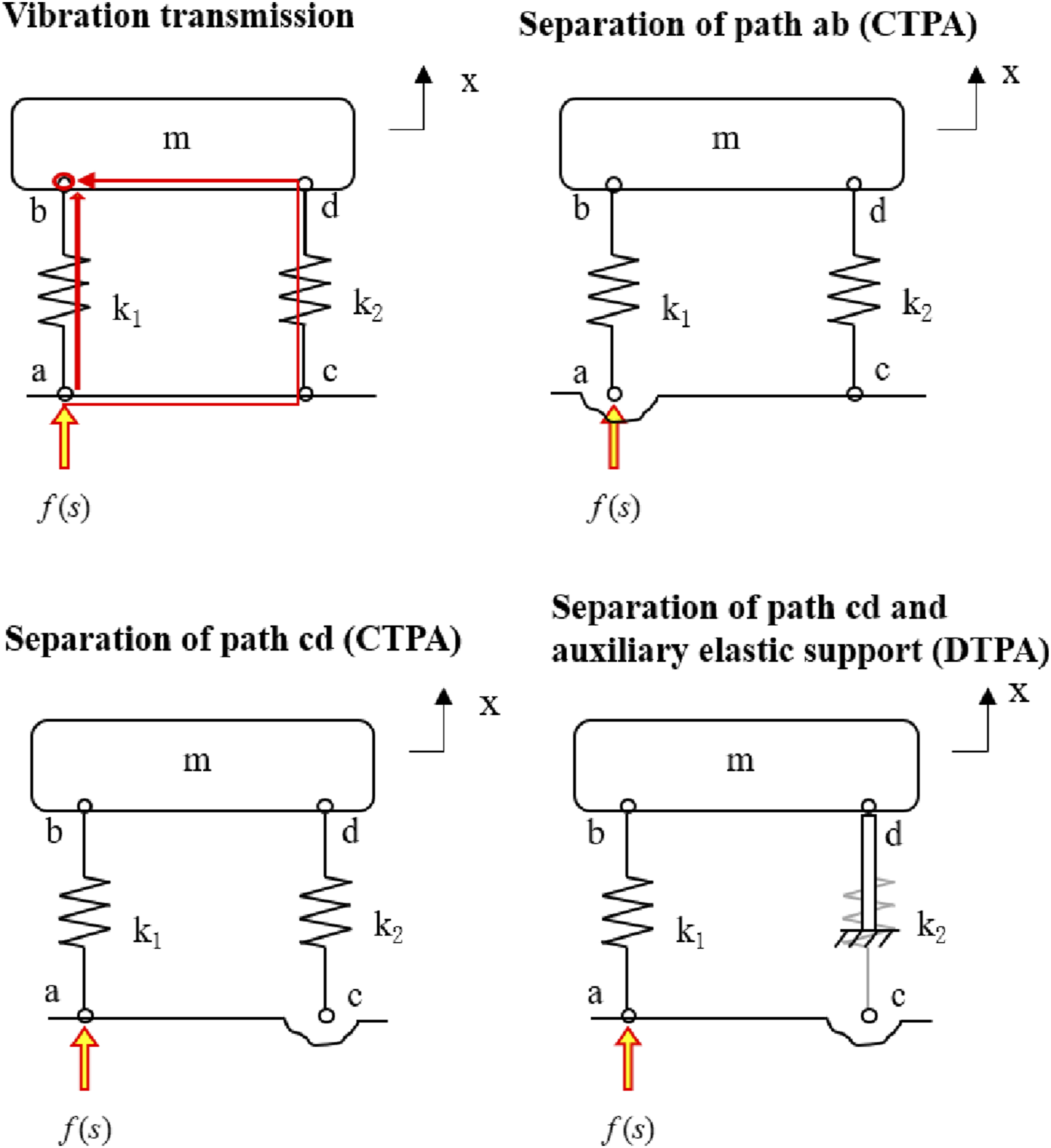
In order to calculate the transfer function of path ab, the excitation is applied at point a, and the vibration is transmitted to the target point b along path ab and path cdb, as shown in Figure 3, the calculated transfer function cannot truly reflect the vibration characteristics of path ab.
The CTPA method is shown in Figure 3. Path ab is separated from the active end, and an excitation source is applied at point a to obtain the transfer function of path ab; or the path cd is separated from the active end, the transfer function of path ab is calculated by applying an excitation source at point a. Although this method solves the problem of coupling between paths, it also changes the boundary conditions and the inherent characteristics. For example, after path ab is removed, elastic element k1 is in a free state, thus changing the natural frequency of the path; or the path cd is removed, the mass m is all loaded by the elastic element k1, which also changes the natural frequency of the path. Therefore, the transfer function of the coupling path cannot be accurately obtained by CTPA method.
In Figure 3, in order to solve the above problems, a DTPA method is proposed. Firstly, the path cd is removed, and the elastic support is installed at point d to ensure that the load quality of spring k1 does not change. Then, the transfer function of path ab is calculated by applying excitation at point a, so that the coupling problem between paths can be solved without changing the inherent characteristics of path ab.
2.2. Implementation of DTPA method
In this part, through the two-degree-of-freedom system model, as shown in Figure 3, the specific implementation process of DTPA method is introduced. Figure 4 a shows a two-free mechanical system with a hybrid structure. The mechanical system is divided into active body M0, passive body M1, and target body M2. The objects are connected to each other by spring and damper. The system consists of two tiers of damping system, tier 1 system contains spring k11, spring k12, damping c11, and damping c12, and tier 2 system contains spring k21, spring k22, damping c21, and damping c22. The external excitation on the active body M0 is transmitted to the target body M2 through four paths (Ha1b1c1d1, Ha1b1c2d2, Ha2b2c1d1, and Ha2b2c2d2), thus causing the vibration of the target body, as shown in Figure 4(b). Two degree of freedom dynamic model. (a) Hybrid system. (b) Vibration transfer paths.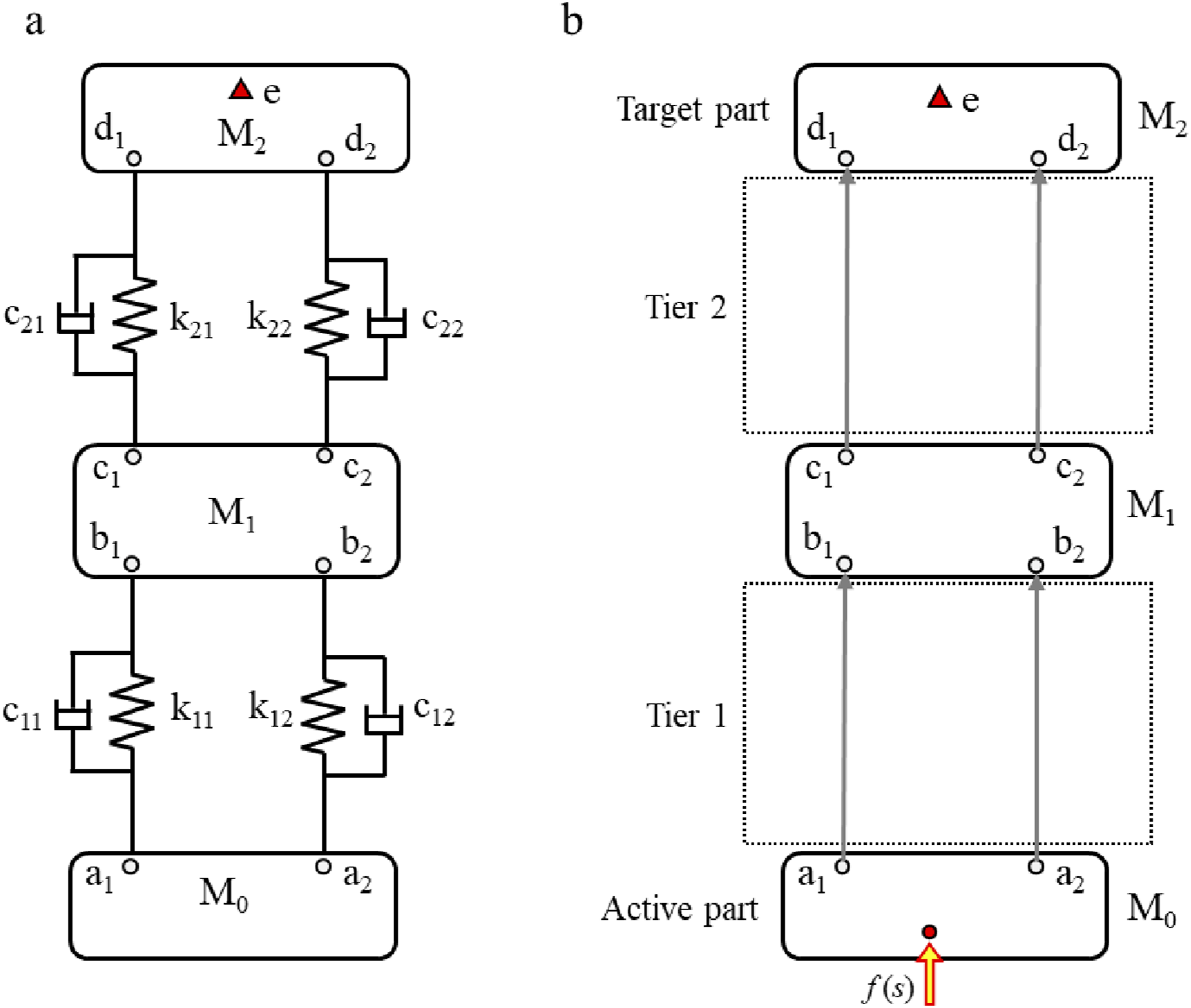
In order to reduce the vibration of the system, the most effective method is to find the main path of vibration transfer and the key subsystems of the main path. In order to avoid the influence of path coupling, CTPA method is usually used to identify the main path. However, the CTPA method has shortcomings in analysis of complex mechanical systems. Therefore, DTPA method is proposed in this paper.
In order to obtain the transfer function of the path Ha1e, the spring k12 in the system of tier 1 is removed, and the elastic support ksb2 is installed on the b2 point of the mass M1, so that the load quality of the spring k11 remains unchanged. Then, the excitation is applied at a1, and the transfer function Ha1e(s) is calculated according to the acceleration signal at point e, as shown in Figure 5(a). The stiffness of elastic support ksb2 is Implementation of the DTPA method. (a) The analysis of the path Ha1e (s). (b) The analysis of the path Ha2e (s).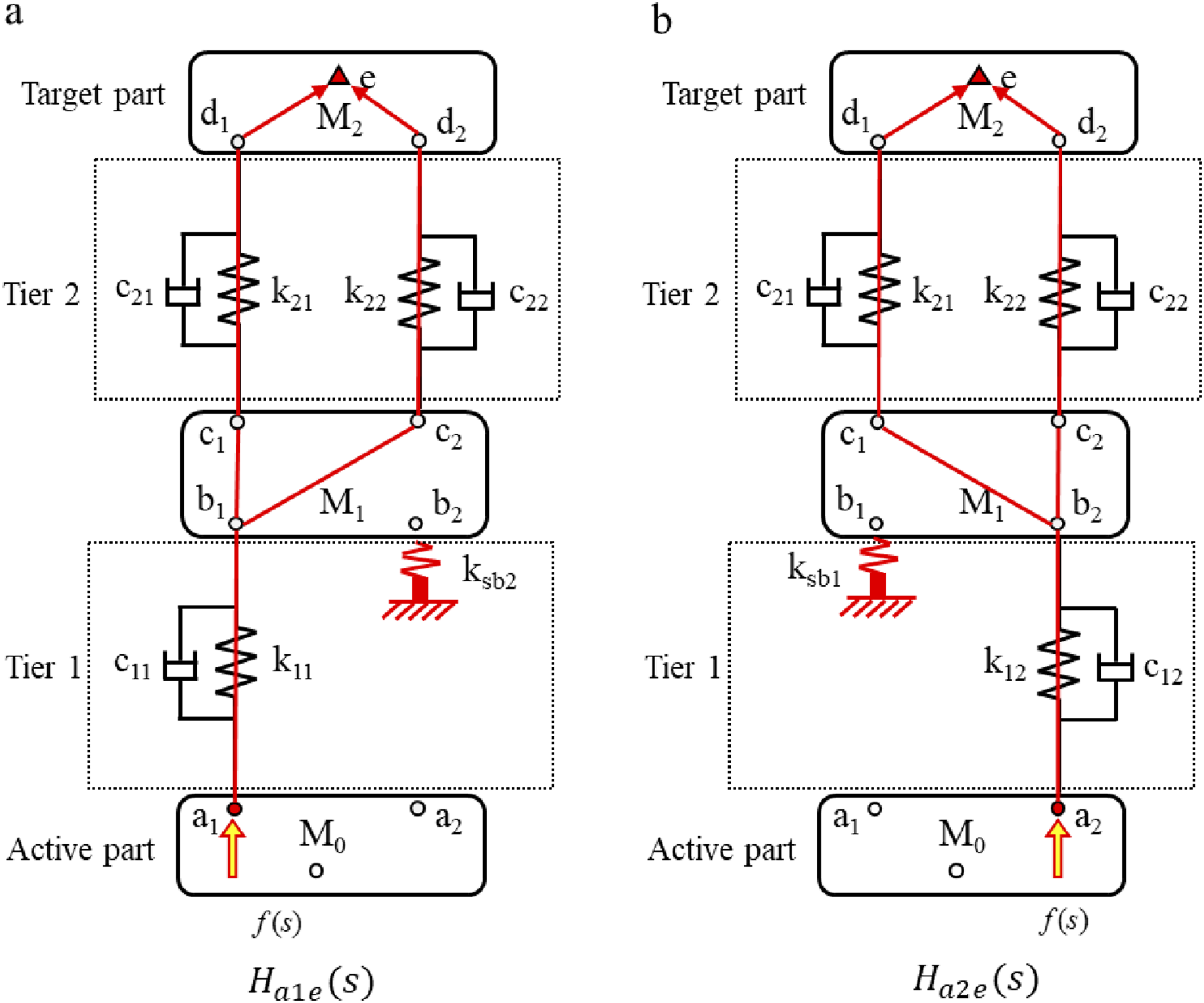

Figure 5(b) shows the analysis of the path Ha2e transfer function. The spring k11 in the system of tier 1 is removed, and the elastic support ksb1 is installed on the b1 point of the mass M1, so that the load quality of the spring k12 remains unchanged. The excitation is applied in a2, acceleration signal of point e is collected, and transfer function Ha2e(s) is calculated. The stiffness of elastic support ksb1 is

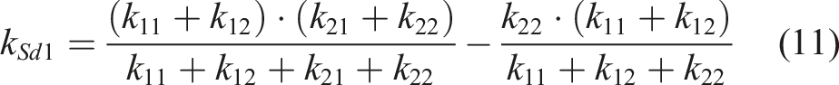
Figures 6 and 7 show the analysis of the transfer function for a single path. Figure 6(a) shows the process of solving the path Ha1b1c1d1e transfer function. Firstly, spring k12 and spring k22 are removed. Then, the elastic support ksb2 is installed at point b2, the elastic support ksc2 is installed at point c2, and the elastic support ksd2 is installed at point d2. Finally, the excitation is applied at point a1 and the transfer function Ha1b1c1d1e(S) is calculated. The stiffness of elastic support ksc2 and elastic support ksd2 are respectively The analysis process of the sub-path transfer function of Ha1e. (a) The analysis of the path Ha1b1c1d1e(s). (b) The analysis of the path Ha1b1c2d2e(s). The analysis process of the sub-path transfer function of Ha2e. (a) The analysis of the path Ha2b2c1d1e(s). (b) The analysis of the path Ha2b2c2d2e (s).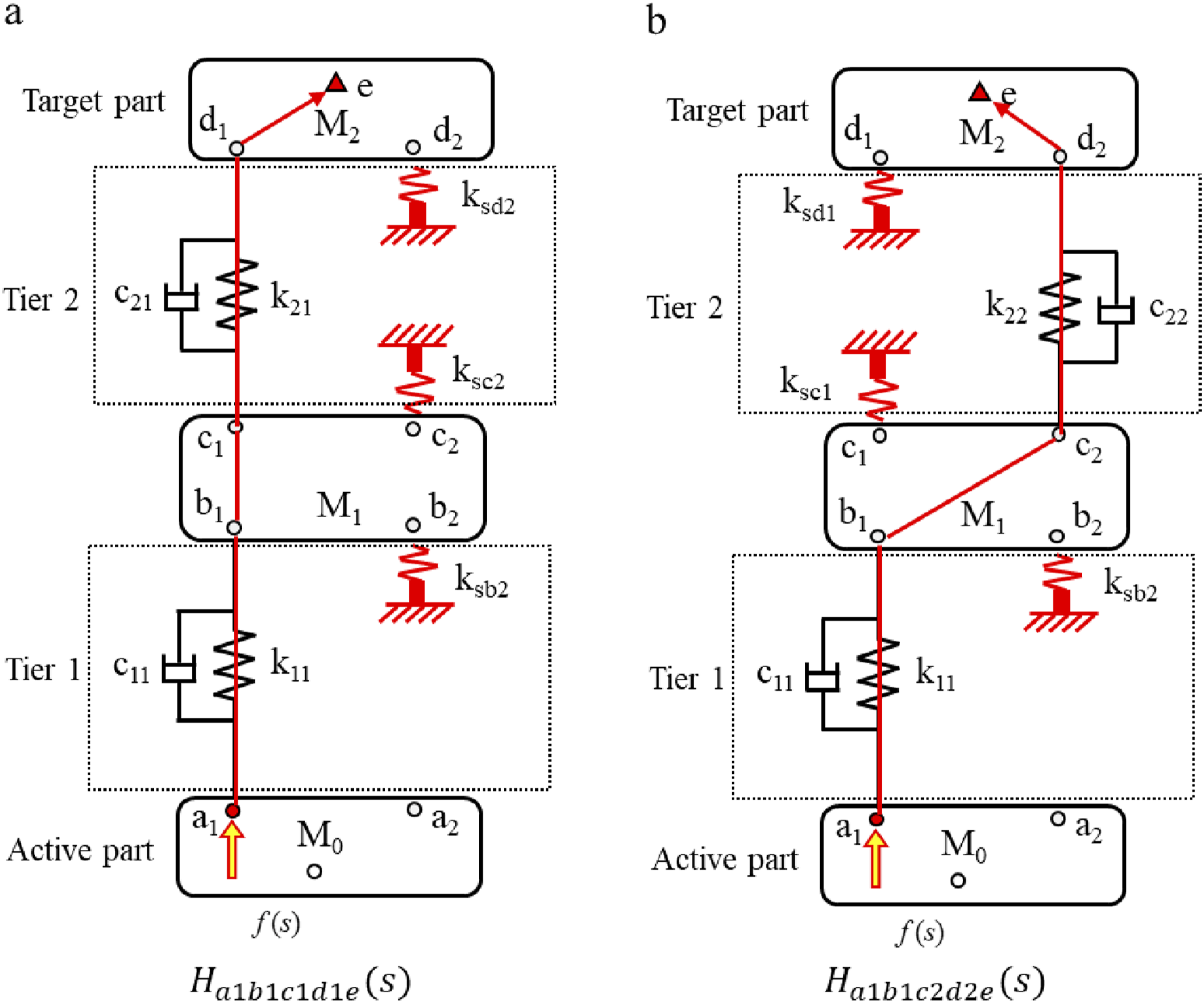
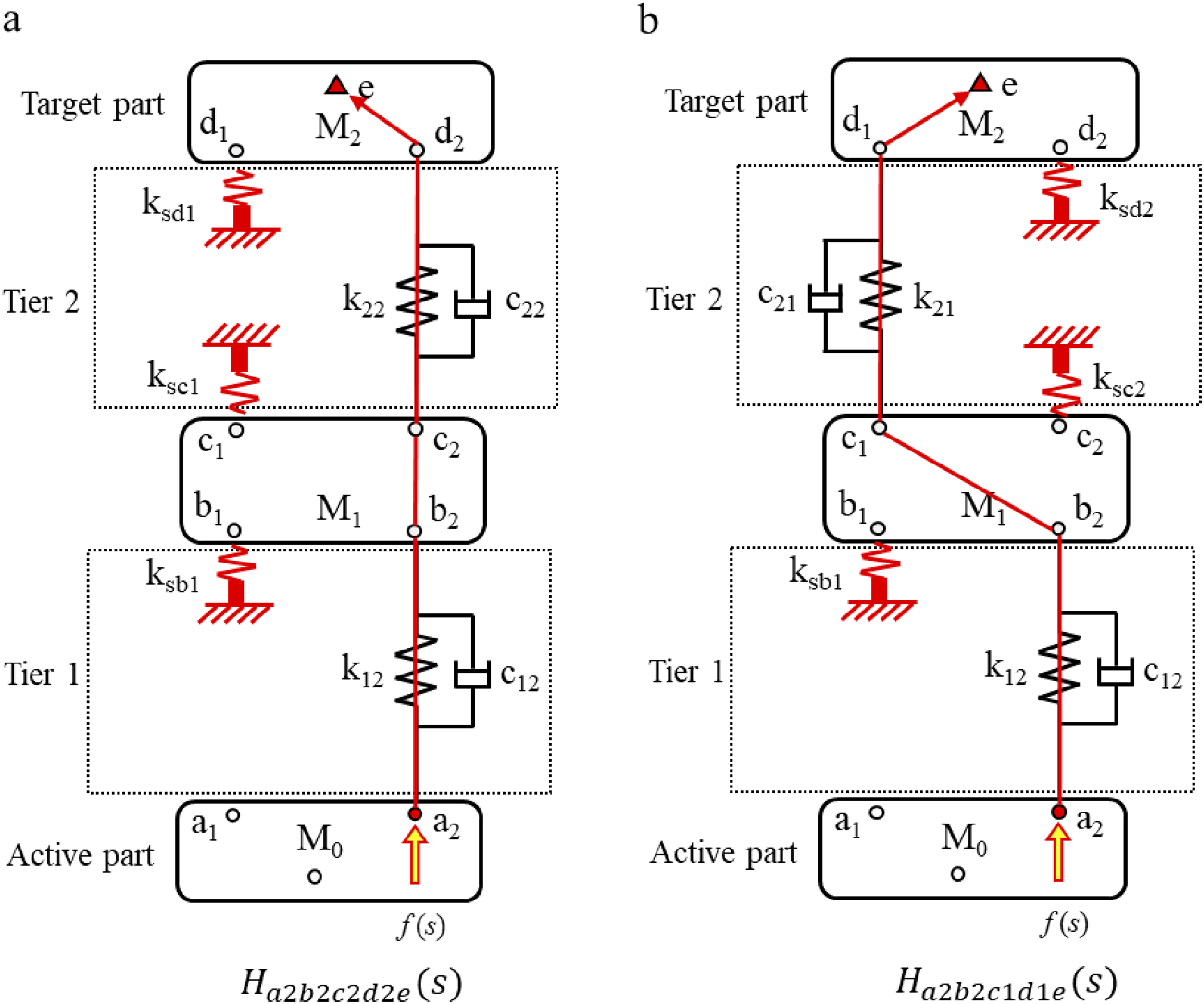

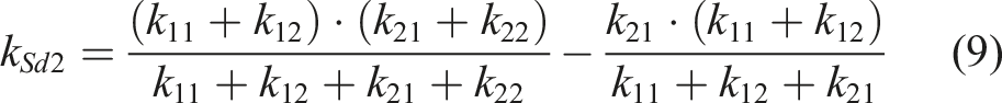
Figure 6(b) shows the process of analysis the path Ha1b1c2d2e transfer function. Firstly, spring k12 and spring k21 are removed. Then, the elastic support ksb2 is installed at point b2, the elastic support ksc1 is installed at point c1, and the elastic support ksd1 is installed at point d1. Finally, the excitation is applied at point a1 and the transfer function Ha1b1c2d2e(S) is calculated. The stiffness of elastic support ksc1 and elastic support ksd1 are respectively

Using the same method, the transfer functions of path Ha2b2c2d2e and path Ha2b2c1d1e are obtained, as shown in Figures 7(a) and (b).
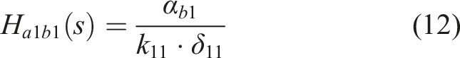
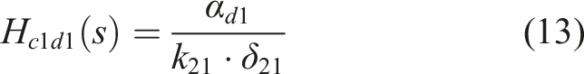
The transfer function of the subsystem can be calculated according to Figure 6(a) and Figure 7(a). In Figure 6(a), the deformation of spring k11 is δ11, and the spring force F11 is k11×δ11. The deformation of the spring k21 is δ21, and the force F21 of the spring is k21×δ21. The response signals of point b1 and point d1 are αb1 and αd1, respectively, there is
3. Numerical example
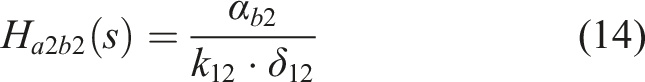
Parameters of the multi-DOF system.
The first frequency of the system is 1.85 Hz, and the second frequency is 11.96 Hz. The transfer function of path Ha1e is shown in Figure 8. There are two peaks by using CTPA method. The first peak frequency is 1.69 Hz, corresponding to the first order natural frequency, and the error between the first order natural frequency of the original system is 8.7%. The second peak frequency is 10.50 Hz, corresponding to the second order natural frequency, and the error is 12.2%. The results show that CTPA method changes the inherent characteristics. The two peak frequencies by using DTPA method correspond to the natural frequencies of the original system, that is, DTPA method does not change the inherent characteristics. Transfer function of path Ha1e.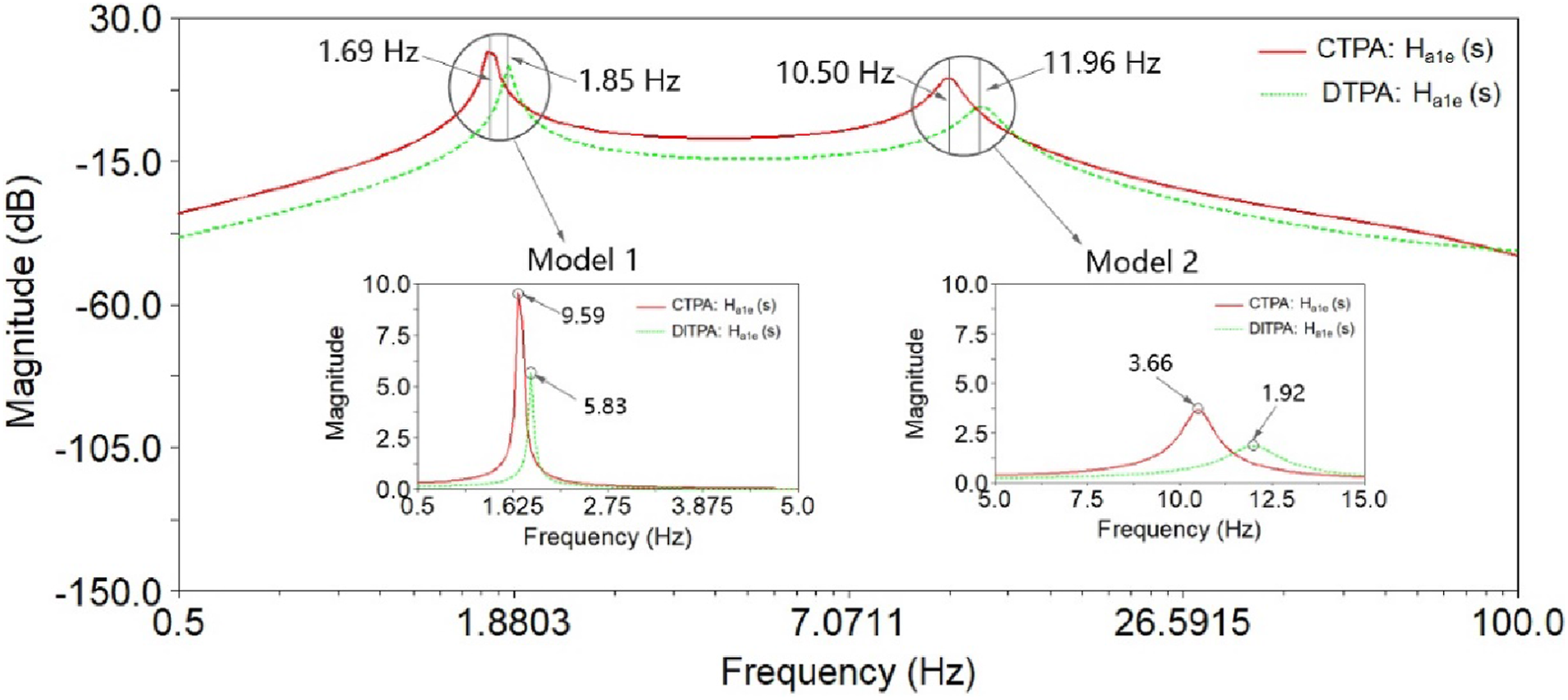
The transfer function analysis results of path Ha2e are shown in Figure 9. By using CTPA method, the first peak frequency is 1.45 Hz, and the second peak frequency is 8.86 Hz, which are different from the original system natural frequencies. By using DTPA method, the first peak frequency is 1.85 Hz, and the second peak frequency is 11.96 Hz, which are almost the same as the original system natural frequencies. Transfer function of path Ha2e.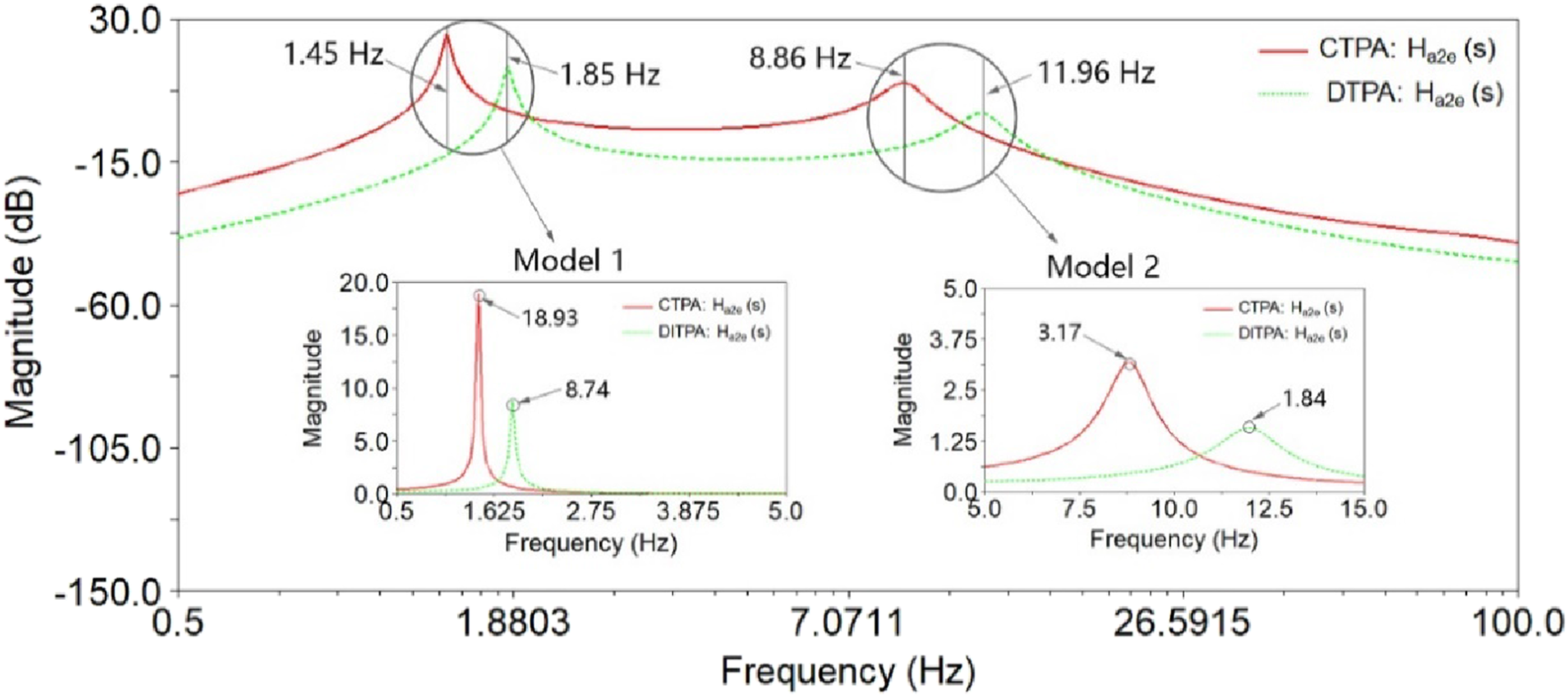
Using DTPA method, the transfer functions of the four paths in the system are calculated as Ha1b1c1d1e(S), Ha1b1c2d2e(S), Ha2b2c1d1e(S), and Ha2b2c2d2e(S), as shown in Figure 10. The first peak frequency of the four paths is 1.85 Hz, and the second peak frequency is 11.96 Hz, that is, the inherent characteristics of the system do not change, and the main path is Ha2b2c2d2e. Transfer function of four paths.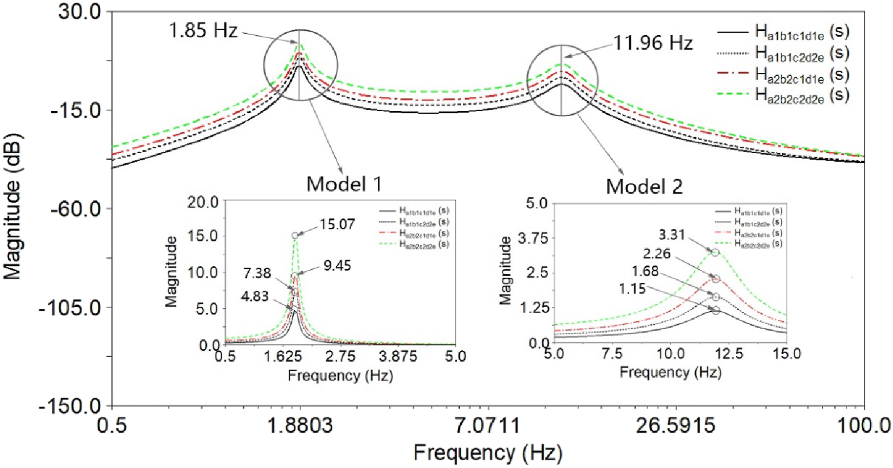
CTPA method achieves path decoupling by disassembly, but the method also changes the inherent characteristics of the system. At the same time, the elastic system after removal is in a free state, under the same excitation conditions, the transfer load also increases. Therefore, the transfer function calculated by CTPA method has obvious deviation. DTPA method overcomes the shortcomings of CTPA method, realizes path decoupling without changing the constraint state and inherent characteristics of the system, and can accurately analyze the path transfer function and key subsystems.
4. Application of DTPA method
4.1. Test description
Engine excitation is the main vibration source of fuel vehicle, which is transmitted to the vehicle body through the mounting system and causes the body vibration. The mounting system plays a crucial role in damping engine vibration. The engine mount system generally consists of three mounts or four mounts. Each mount affects and restricts each other. Therefore, the reasonable matching design of mount system is a tedious work. The transfer path analysis method can identify the main transfer path and key parameters of engine vibration, and provide theoretical basis and reference for mount system design (Park et al., 2012).
As shown in Figure 11, the mounting system consists of left mount, right mount, and rear mount. The upper end of the mount is connected with the engine and the lower end is fixed on the frame. In this paper, the rear mount is the research object to compare the differences between CTPA and DTPA. The excitation is applied to the upper end of the rear mount, and vibration is transmitted to the body through path 1, path 2 and path 3, which are coupled. Therefore, it is impossible to accurately obtain the transfer function of each path without any processing of the mount system. Schematic diagram of TPA analysis of mounting system.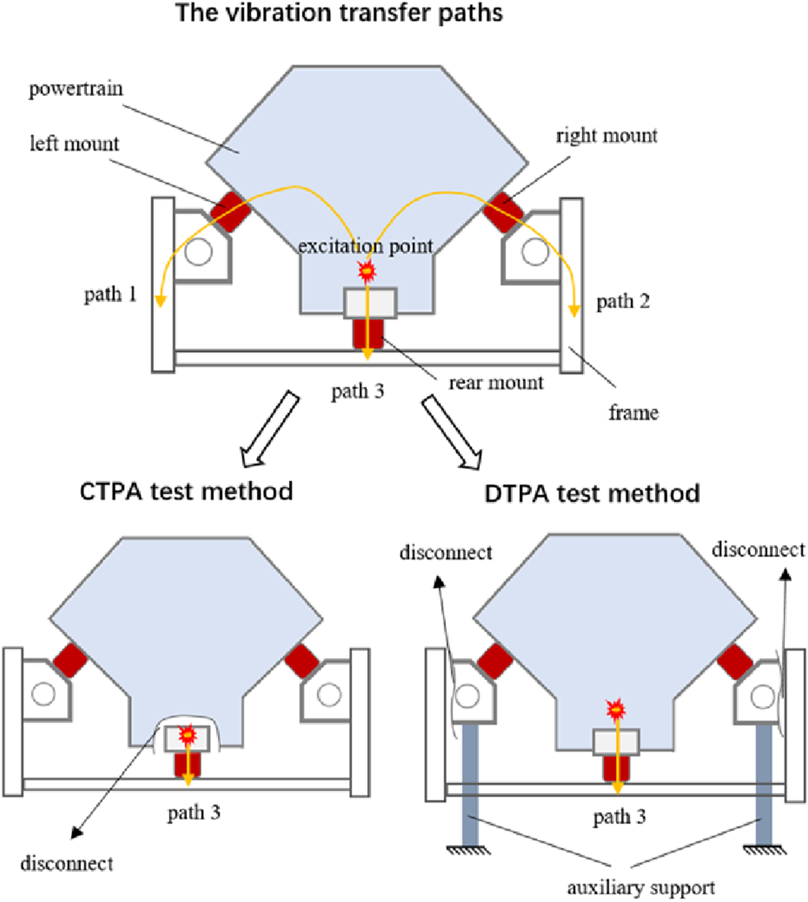
In Figure 11, in order to eliminate the influence of path coupling, the CTPA test method is most widely used at present, that is, the connecting bolt between the rear mount and the engine is removed, and the excitation is applied to the upper bracket of the rear suspension, so that the vibration is only transmitted to the body along path 3, as shown in Figure 11. However, this method changes the support state of the engine, and the natural frequency of the mounting system also changes. Therefore, the transfer function calculated by this method is distorted in some frequency segments.
Figure 11 also shows the application of DTPA in a mount system. First, the connection bolt between the left mount and the engine is removed, and the connection bolt between the right mount and the engine is also removed. Then, the left mount and the right mount are fixed on the elastic supports, and the lower end of the elastic support is fixed on the ground. Finally, the excitation is applied to the engine side at the upper end of the rear mount, and the vibration is transmitted to the body through path 3. This method can accurately calculate the transfer function of each path without changing the natural frequency of the mount system. Figure 12(a) shows the DTPA test process of the mounting system. The test. (a) TPA test of engine mount system. (b) Modal test of engine mount system.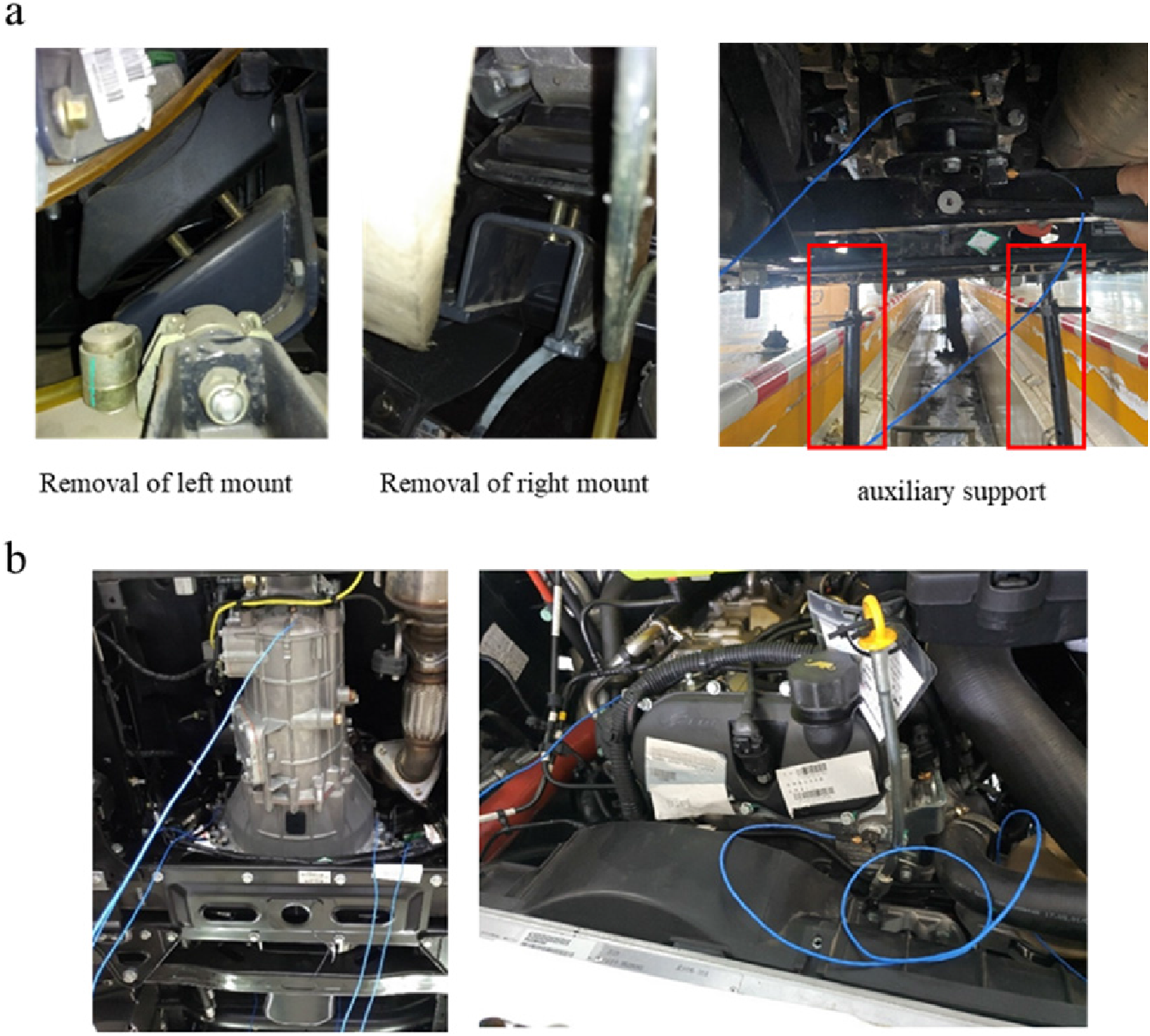
In order to analyze the impact of CTPA and DTPA methods on the natural frequency of the mount system, and the difference between the analysis results, modal test of engine mounting system is required, as shown in Figure 12(b). Four three-way acceleration sensors are installed at the front end of the engine, four three-way acceleration sensors are installed at the front end of the gearbox, and one acceleration sensor is installed at the back end of the gearbox.
The TPA test and modal test are carried out by hammering method. The sampling frequency range is 0-50 Hz, the sampling rate is 0.1 Hz, and the testing equipment is LMS. Test Lab. In the TPA test, the test data often have drift phenomenon in the ultra-low frequency range. Therefore, it is necessary to carry out filtering processing. In this paper, the filtering cut-off frequency is chosen as 0.5 Hz, and the transfer function is calculated according to the output acceleration signal and input load signal. In the modal test, it is necessary to carry out multiple measurements to avoid false frequency and missing frequency phenomenon.
4.2. Test result
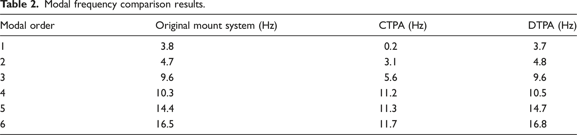
Modal frequency comparison results.
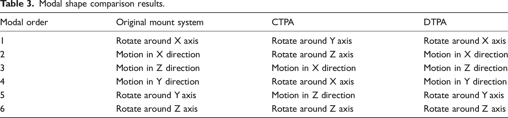
The mode shapes of the original mount system are shown in Figure 13. Table 3 shows the mode shapes of the three states. The comparison results show that DTPA method does not change the mode shape of mount system, while CTPA method changes the mode shape of mount system. The mode shapes of the original mount system. Modal shape comparison results.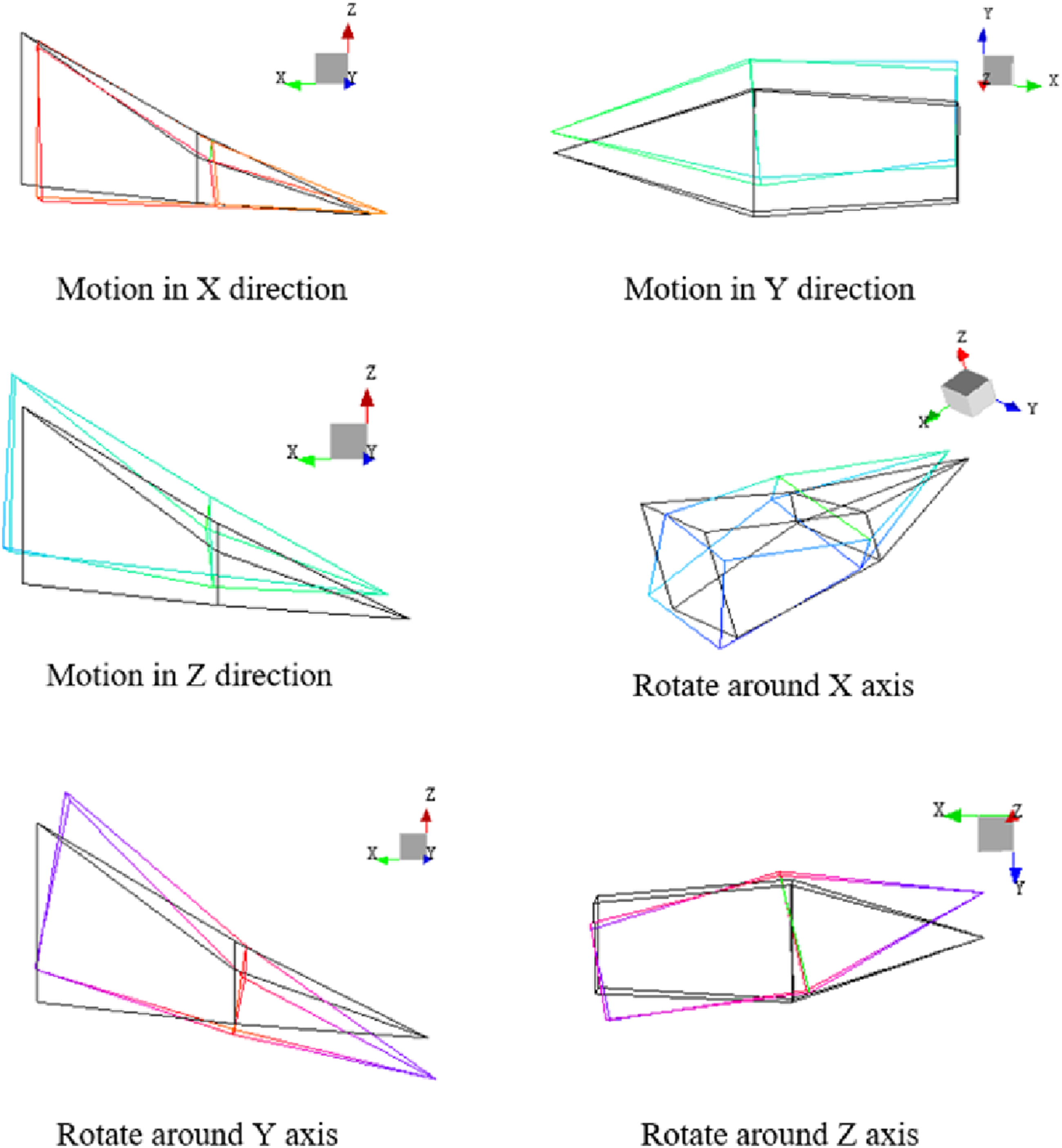
The unit excitation force in Y and Z direction is applied to the upper end of the rear mount, respectively, and the transfer functions of the rear mount-body are calculated according to the acceleration response of the body. Figure 14 shows the comparison of CTPA and DTPA tests, which show that the transfer functions calculated by the two methods are different. TPA test data.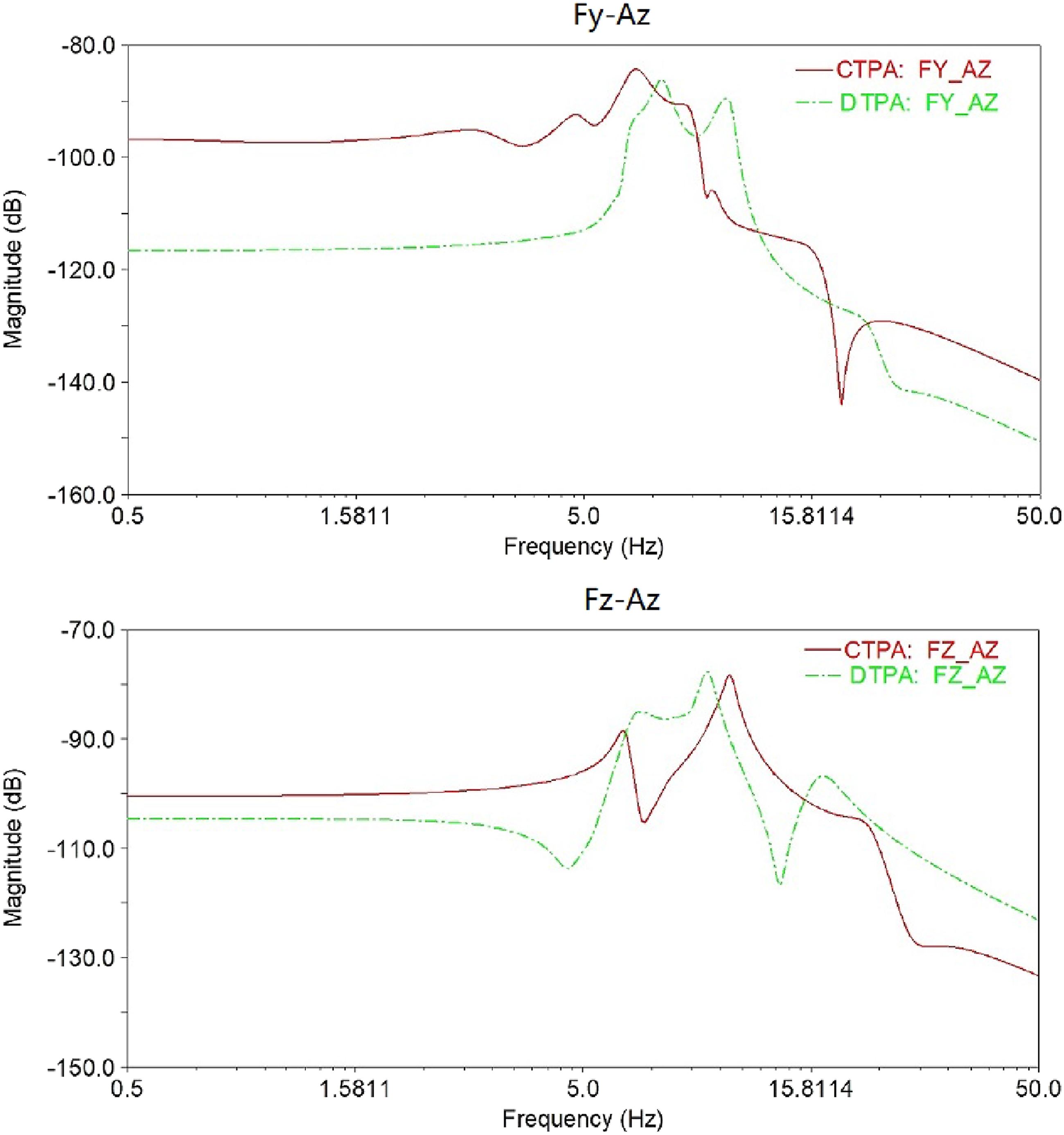
In the frequency range of 0.5–5 Hz, the transfer function amplitude of rear mount Y direction - body Z direction by DTPA method is smaller than that by CTPA method. The amplitude of rear mount Z direction - body Z direction by DTPA method is also smaller than that by CTPA method. In the frequency range of 5.0–50 Hz, the results of the two methods are close, and the main difference is that the peak frequency of the curve is different.
Compared with the mode of the original state, CTPA method changes the inherent characteristics of the mount system, and the calculated transfer function is distorted in the key frequency. While the DTPA method overcomes the shortcoming of the CTPA method, the coupling problem of vibration transfer path can be solved, and the transfer function of each path can be calculated accurately.
The engine is at idle. According to acceleration signals of the upper and lower ends of the rear rubber mount, the deformation data of the mount in X, Y, and Z directions are obtained. The working load is obtained according to stiffness and deformation of the rear rubber mount. The body acceleration is
The comparison of the DTPA results with the experimental data is shown in Figure 15. Figure 15(a) shows the time-domain comparison curve of vehicle body vibration acceleration. The two curves are in good agreement and the acceleration amplitude is close to each other. Figure 15(b) shows the frequency domain comparison curve of the body vibration acceleration, the peak frequencies of test curve are 3.8 Hz, 4.7 Hz, 9.7 Hz, 14.9 Hz, and 15.8 Hz, the peak frequencies of DTPA curve are 3.7 Hz, 4.8 Hz, 9.8 Hz, 14.7 Hz, and 16.6 Hz. The coincidence of the peak frequencies of the two curves is greater than 90%. The comparison results show that DTPA method is correct. Vibration data. (a) Time domain data. (b) Frequency domain data.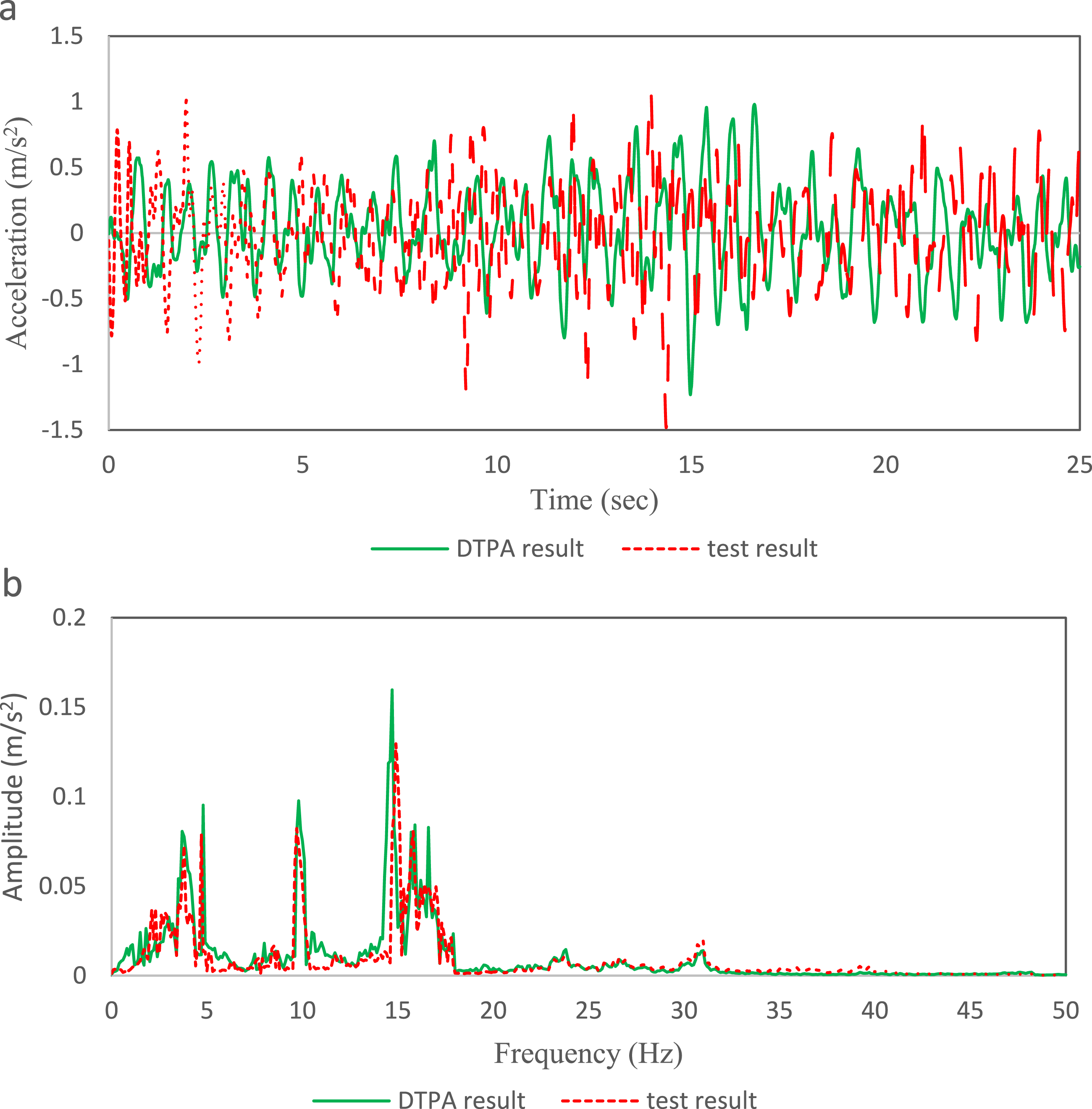
5. Conclusion
In this paper, the difference between the classical transfer path analysis (CTPA) method and the decoupled transfer path analysis (DTPA) method in solving the path coupling problem is analyzed by numerical simulation. The peak frequency of the transfer function calculated by CTPA method is different from the natural frequency of the system, and the peak frequency calculated by DTPA method is the same as the natural frequency of the system. The results show that CTPA method changes the inherent characteristics of the system, while DTPA method overcomes the shortcomings of CTPA method, and improves the path decoupling accuracy without changing the boundary conditions of the system.
CTPA method and DTPA method are used to test the vibration transfer function of the engine mount system, and the test results show that there are differences between the two methods, especially the peak frequency on the curve is obviously different. The main reason is that CTPA changes the natural frequency and modal shape of the mount system compared with DTPA. The experimental results are in good agreement with those of numerical analysis. Therefore, the DTPA method can realize the decoupling of vibration transfer paths, avoid the path crosstalk problem, and calculate the transfer function of each path accurately.
Footnotes
Acknowledgments
The authors would like to acknowledge the support of Naveco Automobile Co., Ltd for providing the materials and apparatus to carry out the experimental works.
Declaration of conflicting interests
The author(s) declared no potential conflicts of interest with respect to the research, authorship, and/or publication of this article.
Funding
The author(s) disclosed receipt of the following financial support for the research, authorship, and/or publication of this article: This work supported by NAVECO NVH promotion project (2022HVH102).