
Abstract
Dilatant fluids exhibit a sudden increase in viscosity when the shear rate increases. This characteristic can be used in the design of bearings that can suppress vibrations in the event of a sudden increase in shear rate, such as in rotating machinery. The bearings for rotating machines are designed based on a model that uses dynamic coefficients of the rotor. Therefore, in this study, the bearing coefficients of a squeeze film damper (SFD) using a dilatant fluid were experimentally determined. These characteristics were compared with those of a typical SFD using oil.
1. Introduction
Squeeze film damper (SFD) bearings are widely used in various industrial applications such as aircraft engines, gas turbines, and hydraulic dampers (Andres and Jeung, 2016; Andres et al., 2016; Gehannin et al., 2009). The structure of the SFD covers the rolling bearing with an oil film layer consisting of an inner ring that rotates together with the shaft to hold the shaft, an outer ring that supports the outer periphery, and an oil film layer that covers the outer ring (Andres, 1996; Kobayashi, 1996a; Kuzdzal and Hustak, 1996). The outer ring was fixed in the rotational direction, but not in the translational direction. When vibration occurs in the rotational axis, flow and compression of the oil film layer are induced, and damping can be achieved by the resistance force generated by the oil film layer (Koike and Ishihara, 1983; Kobayashi, 1996a, Kobayashi, 1996b; Jeung et al., 2016). To vibration suppression performance, the novel shape of fluid damper named a circular arc spring damper is proposed in the previous study (Takeuchi et al., 2021).
In contrast, a dense mixture of particles and liquid typically exhibits fluidity under normal conditions. However, when the flow state exceeds a certain shear rate, the viscosity suddenly increases due to shear thickening and appears to harden. This phenomenon is called dilatancy and fluids with these characteristics are known as dilatant fluids (Jacek et al., 2023). Typically, the mass around the axis of rotation of a rotating machine is balanced and the machine rotates accordingly. However, if this balance is disturbed, significant vibrations can occur, leading to failure or destruction of the machine. It is assumed that these vibrations can be suppressed with the help of this characteristic.
An electrorheological (ER) fluid has been cited as an example of a damper that uses nonlinear fluids such as dilatant fluids as the operating fluid for SFD (Morishita and Mitsui, 1990). The viscosity of the ER fluid changes in response to the applied electric field, so it can continuously change the support mode of the shaft and provide optimal damping according to the rotational speed. There are also reports on the use of dilatant fluids in dampers (Masuda et al., 1997). A material with dilatant characteristics was enclosed in a dashpot-type damping element and its characteristics were investigated experimentally. It was shown that by using dilatant materials, it is possible to create a damping element that suppresses vibrations when large vibrations, such as those caused by resonance or impact forces, may occur and provides vibration isolation under steady-state conditions. While attempts have been made to develop vibration damping devices that use the characteristics of nonlinear fluids, there have been no examples of the use of dilatant fluids in bearings, such as SFDs.
In this study, we propose that an SFD was developed that applies a dilatant fluid. The novelty of this paper consists of following two points. The first point is to apply dilatant fluid to squeeze film damper (SFD) instead of oil. The major feature of dilatant fluid is severe shear thickening. The viscosity of the fluid increases nonlinearly by orders of magnitude at a certain critical shear rate. When the SFD uses the dilatant fluid, it can suppress abnormal vibrations caused by the strong impact or accident in rotating machineries. In addition, the viscosity tends to be lower than that of oil under the critical shear rate. Therefore, the proposed SFD does not hinder the normal operation of the machine but can suppress abnormal vibrations only when they occur by utilizing the shear thickening behavior of the dilatant fluid. The second point is development of identification method of rotor dynamic coefficient for the proposed SFD. The identification of the rotor dynamic coefficient of supporting structure is essential to design the actual rotating machineries. Engineers analyze the dynamics of the rotating machineries based on the coefficient. The identification has been already proposed in the typical SFD using oil, however, the proposed SFD uses the dilatant fluid which is non-Newtonian fluid. In this study, we develop the identification method of the coefficient to employ the actual rotating machineries with the proposed SFD.
For feasibility study, we have developed a test bench which has the active magnetic bearing (AMB). The AMB can realize the arbitrary condition for measurement of rotor dynamic coefficients of the SFD (Yabui and Inoue, 2019; Yabui et al., 2021). Based on the measurement results, we estimate the dynamics when a dilatant fluid is applied to the SFD and clarified its characteristics compared to oil (Turbine Oil 32), which is commonly used as the operating fluid for the oil film layer in the SFD.
2. Squeeze film damper
Sliding and rolling bearings are the two primary varieties of bearings. Rolling bearings maintain rotation by a ball rolling between the inner and outer rings. Figure 1 indicates the structure of a typical SFD. They have the advantage of being strong under large loads. Sliding bearings maintain rotation by having oil carried into the gap between the stationary and rotating parts. They have the advantage of a longer service life. However, rolling bearings suffer from ball damage owing to point contact under load, and sliding bearings have the disadvantage of self-excited vibrations caused by the interaction between the oil and the bearing (Iwatsubo et al., 1989; Iwatsubo and Ishimaru, 2010). To combine the advantages of these bearings, the SFD was developed. An SFD has a structure in which the area around the rolling bearing is covered with a layer of oil. Damping is achieved by using the resistance created by the flow and compression of the fluid caused by vibrations (Saito and Kobayashi, 1982; Kamiyoshi et al., 2004). Because the damping effect of an SFD varies depending on the gap design, many studies have been conducted on its effect. If the gap is too small, the oil film can break, resulting in ineffective damping. However, if the gap is too large, not only is the damping effect ineffective, but the rotating shaft may also bend and vibrate owing to vibration. Structure of the squeeze film damper.
3. Characteristic of dilatant fluid
Dilatant fluids are nonlinear fluids that exhibit a significant increase in viscosity in response to sudden external forces or strong vibrations. The most commonly used material for this phenomenon is a mixture of water and corn starch. This phenomenon can be explained using Figure 2(a) as described in the previous study (Masuda et al., 1997). In a dispersed system, the dispersed particles are in the most closely packed state; therefore, the interstices of the particles are sufficiently filled with the dispersion medium. Feature of characteristic of dilatant fluid.
When flow is applied to this state, the particles change from the most closely packed state to a loosely packed state, and the interstices between the particles increase. Therefore, the dispersion medium becomes relatively less dispersed, and the particles come into direct contact with each other, causing the apparent viscosity to increase and become hard. If the particles remain undisturbed, they return to the most closely packed state and become fluid. This change in viscosity is a dilatancy phenomenon. Figure 2(b) shows a conceptual diagram of the relationship between shear rate and viscosity (Masuda et al., 1997). A linear Newtonian fluid has a constant viscosity regardless of the shear rate, whereas a dilatant fluid exhibits a sudden increase in viscosity at a critical shear rate. In this study, a mixture of water and corn starch was used as a dilatant fluid.
4. Measurement system
4.1. Experimental device
Figure 3(a) shows a photograph of the apparatus used for the experiment. The actual SFD consists of an inner wheel (rotating part) and an outer wheel (fixed part). However, to study the interaction between the fluid and the vibration of the outer wheel in this experiment, a steel rod was used as a substitute for the axis corresponding to the outer wheel of the SFD. The axis was mounted vertically via a flex coupling and could move freely. Electromagnets were placed at four points around the axis, and the axis could be vibrated in any direction by controlling the current flowing through the electromagnets. The number of turns in the electromagnets was 250, and an iron core was used in the coil. Developed experimental system.
Figure 3(b) shows a schematic representation of the experimental setup. To investigate the effects of large-amplitude vibrations and to compare the characteristics with those of oil, the clearance was increased beyond that of a conventional SFD in this experiment.
4.2. Overview of the measurement system
To determine the dynamic characteristics of the SFD using a dilatant fluid, an excitation test was performed with the AMB, and the dynamic rotor coefficients were determined from the experimental data. Rotor dynamic coefficients are often used in the experimental modeling of rotating machines. Based on this modeling method, an approximate model of the SFD as a spring–mass–damper system was created (Figure 4). However, because the dynamic characteristics of an SFD using a dilatant fluid are believed to depend on the vibration amplitude, orbit, and vibration frequency of the axis, they cannot be determined with simple random excitations or sweep signals. Therefore, it is necessary to reproduce arbitrary experimental conditions in an actual system using active control with an AMB. Under these conditions, closed-loop system identification was performed using the control and axis displacement signals to identify the dynamic characteristics of the SFD with a dilatant fluid. Diagram of the spring–mass–damper model.
4.3. Rotor dynamic force measurement
A block diagram of the active control system for controlling the AMB is shown in Figure 5. In this system, there is almost same transfer characteristic of G, M, and P in x- and y-direction. PD controller C is commonly used for active control of AMBs. However, the purpose of this experimental setup was not only to stabilize the AMB, but also to reproduce the desired experimental conditions. Because we want to confirm the response of the SFD in any excitation direction, trajectory tracking control of the excitation command value is required. Therefore, the PD controller is insufficient for this purpose. Moreover, because the output of the PD controller contains signals over a wide frequency range, it is unsuitable to estimate only the excitation frequency signal from the control signal by inverse calculations. Block diagram of the control system of the AMB.
Therefore, in this study, a control system was developed using adaptive feedforward cancellation (AFC) to compensate for external forces and track the target trajectory (Messner and Bodson, 1995; Yabui and Inoue, 2019; Yabui et al., 2021). The block diagram shown in Figure 5, which corresponds to the AFC, is placed in parallel with the PD controller.
Assuming that the dynamic characteristics of the SFD with a dilatant fluid can be represented by a spring–mass–damper model based on the SFD-generating force at each frequency estimated from the AFC output, the relationship between the SFD-generating force and rotor dynamic coefficients
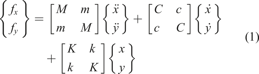
The normal force


The bearing constants can be determined by fitting the experimentally determined fluid forces at the angular frequencies.
4.4. Fluid force measurement considering nonlinearity
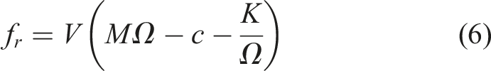
Although it is possible to obtain the rotor dynamic coefficients and bearing constants using equations (3) and (4), in the case of circular orbit excitation with a constant radius, the velocity in the circumferential direction increases with increasing orbital frequency, because the velocity is given by the product of the radius and angular velocity. In the case of a dilatant fluid, the viscosity increases sharply with the deformation rate of the fluid. Therefore, it is natural to create the model under the condition of a constant velocity. Therefore, tests were performed in this study, in which the axis was vibrated at a constant velocity. As mentioned earlier, the velocity is given by the product of the orbital radius r and the angular velocity Ω, so the orbital radius is varied to maintain a constant velocity as the orbital frequency increases. The relationship between these two quantities is shown in Figure 6. The condition of constant velocity V can be expressed as follows: Relationship between the orbital radius and angular velocity.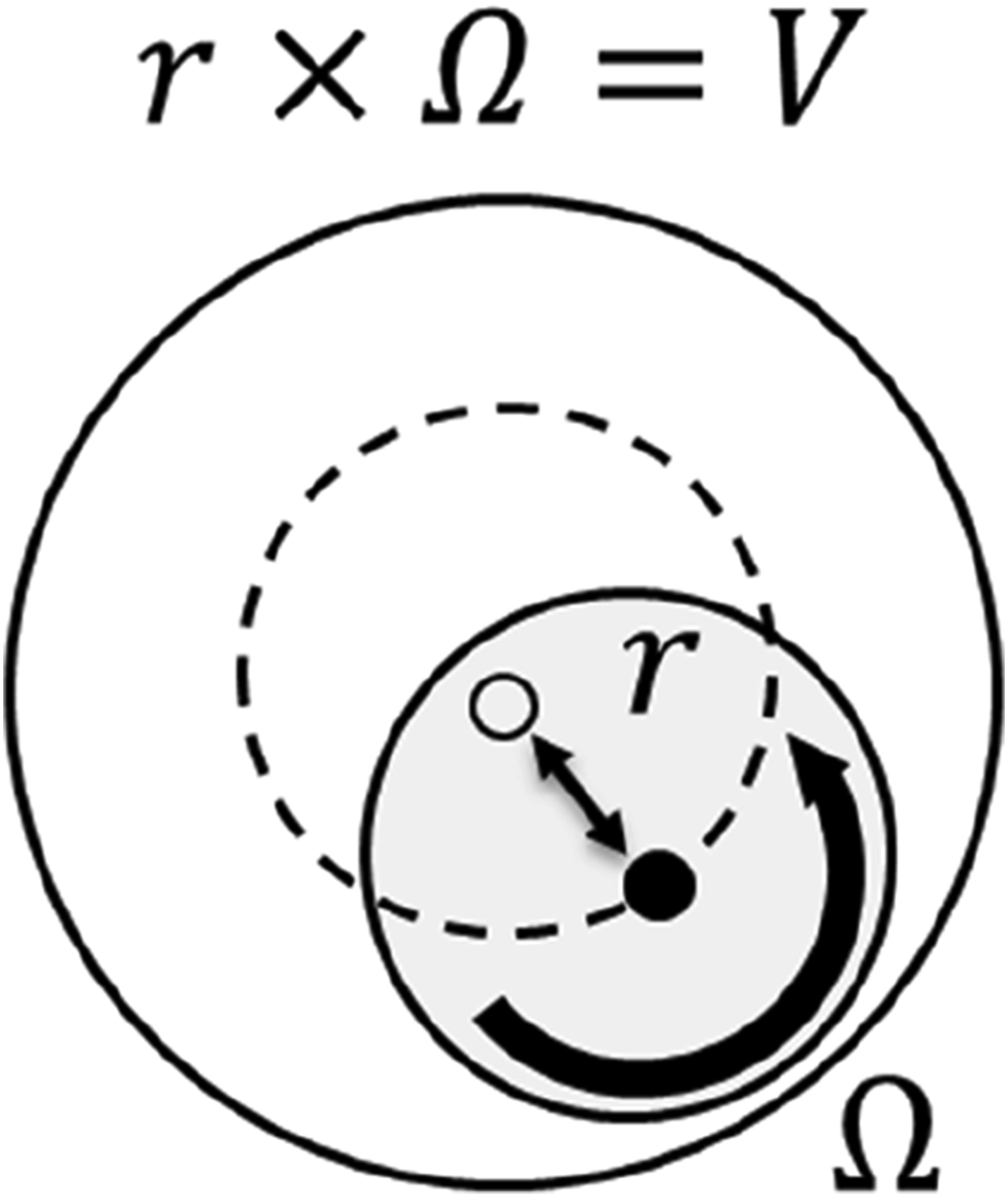

The relationship between the SFD-generating force under a constant velocity condition and each coefficient can be expressed by the following equation by substituting the above equation into equations (6) and (7):
To elucidate the rotor dynamic coefficients of a shear-thickening fluid with strong nonlinearity, a vibration test was performed in this study under constant velocity conditions.
5. Experiment for the measurement of rotor dynamic coefficients
5.1. Test condition
In this study, the dilatant fluid is a thick mixture of water and corn starch called Oobleck (Krishna et al., 2021), whose viscosity increases discontinuously in response to sudden deformation. When the rotating shaft is moved suddenly by the external force through the dilatant fluid, the surface dries out and the mixture hardens. When the external force is applied slowly, the liquid acts as a lubricant between the powder particles and the mixture behaves like a fluid. On the other hand, when the external force is applied suddenly, it shows great resistance and behaves like a solid.
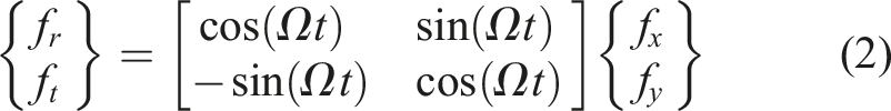
The dilatant fluid was prepared by mixing water and cornstarch at a weight ratio of 1:1.05. The dilatant fluid was placed in the end of shaft as shown in Figure 3. An electromagnetic controller was used to set the axial whirling radius and frequency, and the excitation was applied. The purpose of this study is to measure the rotor dynamic coefficient of the proposed squeeze film damper using dilatant fluid. The feature of dilatant fluid is dependent on the angular velocity of rotor. In addition, the measurement needs the forces f
r
, f
t
at multiple angular frequencies to calculate the rotor dynamic coefficient by fitting equations (6) and (7). Therefore, to keep the measurement condition, this study proposes to measure the coefficient normalized by the angular velocity. First, the target angular velocity V = 22.6, 31.4, 45.2 mm/s is decided, second, the measurement points of angular velocity Ω = 5, 10, 15, 20, 25 *2π [rad/s], and finally, the radius is r decided for each Ω; the value of radius r and angular velocity Ω is decided to keep the constnat value calculated from equation (5). Figure 7 illustrates the variation of the whirling radius r and whirling frequency Ω for each velocity V. The fluid forces obtained from the experiments for each rotational speed and radius were compared with the theoretical formulas and fitted accordingly. Variation of the orbital radius for each at Ω and three cases of velocity V.
The confirmation of trajectory tracking was crucial in the experiments. This is because, the excitation tests were conducted under constant velocity conditions. Figure 8 shows the target trajectory of the shaft observed during the excitation experiments. This was the result of verifying the tracking performance in an actual test using a dilatant fluid consisting of water and corn starch mixed at a weight ratio of 1:1.05, with each velocity V. The outermost circle represents the initial rotational radius, which decreased with increasing rotational frequency. Target trajectory of the rotating shaft for each Ω.
5.2. Measurement results
The whirling radius r and whirling frequency Ω are controlled by the control system with AFC. The measurement results: rotor trajectory, time responses of rotor position, and amplitude spectrum of rotor position are indicated in Figure 9 for typical SFD using oil, in Figure 10 for proposed SFD using dilatant fluid. In Figures 8–11, the legend is the value of Ω converted in Hz for ease of understanding. The whirling position of the rotating shaft has only the frequency component at each Ω. The rotating shaft can be tracking preciously for the target trajectory in both cases of SFD. The objective of this study is to realize same operating condition (namely, tracking the target trajectory) in both cases of SFD for fairly comparison of the rotor dynamic coefficients. These figures indicate the almost same operating conditions in both cases of SFD, it means that the characteristic of rotor dynamic coefficients in both cases of SFD can be measured in same conditions. Summary of experimental results: typical SFD using oil. Summary of experimental results: proposed SFD using dilatant fluid. Summary of measurement results of 
Although there is no difference in the measured rotor position in both cases of SFD, the measured forces f r and f t are the difference between the typical SFD using oil and the proposed SFD using dilatant fluid. Figure 11 indicates the measured forces f r and f t of each SFD. In the case of typical SFD, the values of f r and f t are the same trend; f r and f t are almost the same value in every Ω at each velocity V. In the case of the proposed SFD, the variation of f r and f t are bigger as increasing the velocity V. It means that the proposed SFD has different characteristic dependent on V.
5.3. Prediction of rotor dynamic coefficients
The results of fitting the fluid-generating force obtained from the experiments are shown in Figure 11. The fitting results are obtained from the following equation. Curve fitting results for the typical SFD using oil. Curve fitting results for the proposed SFD using dilatant fluid.
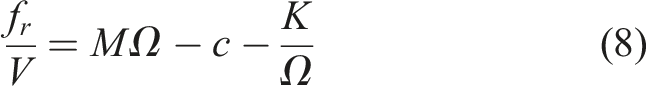
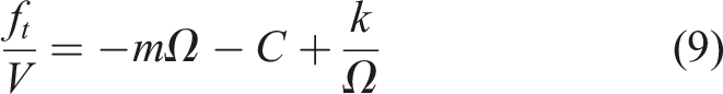
Figure 14 compares values of M, C, K, m, c, and k. The values of coefficients M, c, and k are almost the same values in both SFD, and these doesn’t change in any velocity. For the coefficient m, the values are the difference in each SFD and it has velocity dependency. The value of m is not zero, the characteristic of SFD is coupled in x-y direction. For the coefficient C, the value of the dilatant fluid exceeded that of oil at a velocity of 45.2 mm/s. The value for coefficient K also increased sharply at a velocity of 45.2 mm/s. These observations indicate that the shear thickening phenomenon of the dilatant fluid is governed by both the damping and spring characteristics. The variation comes from the characteristic of dilatant fluid; when the external force is applied suddenly, it shows great resistance and behaves like a solid. The characteristic is useful to suppress the vibration due to the external force in the rotating machineries. Comparison of the values of M, C, K, m, c, and k between typical SFD (oil) and proposed SFD (dilatant).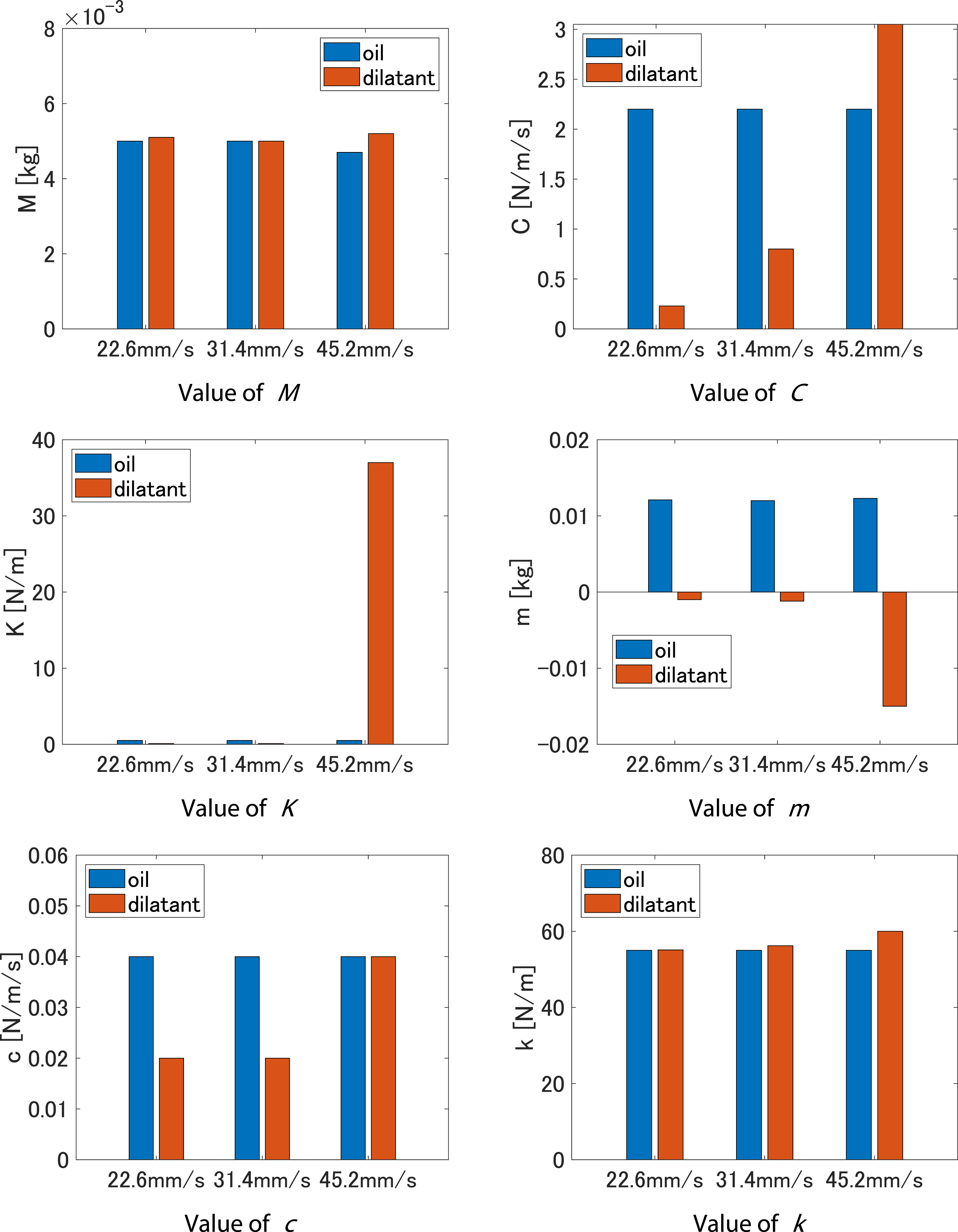
In contrast, the values of the coefficients C and K for oil remained constant, indicating the linear characteristics of oil. It is also generally claimed that for oil, the rotor dynamic coefficients remain constant regardless of the velocity, particularly at wider clearances. This experiment also confirmed the validity of these results as the rotor dynamic coefficients of the oil remained constant.
5.4. Different conditions in the proposed SFD
We measured f
r
and f
t
for different mixing ratio of water and corn starch for 1:1 (lower viscosity) and 1:1.1 (higher viscosity), and the measurement results are shown in Figure 15(a). The measurement condition is velocity V = 45.2 mm/s at each angular velocity Ω = 5, 10, 15, 20, 25*2π [rad/s]. With comparison to the original mixing ratio (1:1.05), the higher viscosity of the fluid leads to better damping effects. However, if the ratio of corn starch is more increased, the rotor system can’t track the target trajectory due to the high viscosity. It is due to torque limitation of the motor. Therefore, the mixing ratio should be decided to obtain enough damping effects within the range of torque limitation. Prediction results in different conditions about three cases of mixing ratio of water and corn starch, three cases of temperature in the proposed SFD using dilatant fluid.
In addition, we measured f r and f t for three temperature condition: 5-degree, 10-degree (original), and 20-degree, and the measurement results are shown in Figure 15(b). The measurement condition is velocity V = 45.2 mm/s at each angular velocity Ω = 5, 10, 15, 20, 25*2π. [rad/s]. The higher temperature of the fluid leads to better damping effects. Previous studies have reported that the viscosity of a dilatant fluid is proportional to heat (Arunachalam and Rajappa, 1978; Sreelakshmi and Sarojamma, 2018). Therefore, it is expected that the values of C and K will increase with heat.
5.5. Verification of vibration suppression performance
To verify the effectiveness of the proposed SFD, vibration tests were performed in the experimental system. In this test, sine signal was input to controller output u
y
in Figure 5. The time response of sine signal is shown in Figure 16. The amplitude of sine signal gradually increases for 100 s. The equation of sine signal is defined as 0.04 t cos(40πt). The velocity of the rotor gradually increases from 0 mm/s to about 55 mm/s in 100 s. The time responses of y are also shown in Figure 16. For comparison, the vibration tests were performed for cases without SFD (empty), the typical SFD (oil), and the proposed SFD (dilatant). The typical SFD can suppress the vibration compared to case of without SFD. Moreover, the proposed SFD can suppress the vibration compared to the conventional SFD as the velocity increases. The relationship between the velocity of the rotor and amplitude of y is shown in the bottom of Figure 16. The amplitudes of y in the cases of the typical SFD and proposed SFD are almost the same as the velocity lower than about 30 mm/s. On the other hand, the amplitude of y in the case of the proposed SFD is smaller than that of the typical SFD as the velocity is higher than 40 mm/s. This result can be considered to be due to the significant change in the values of C and K when the velocity of the rotor increases between 31.4 mm/s and 45.2 mm/s, as shown in Figure 14. The proposed SFD can reduce vibration more effectively compared to the typical SFD when the rotor speed increases. Experimental results of vibration tests.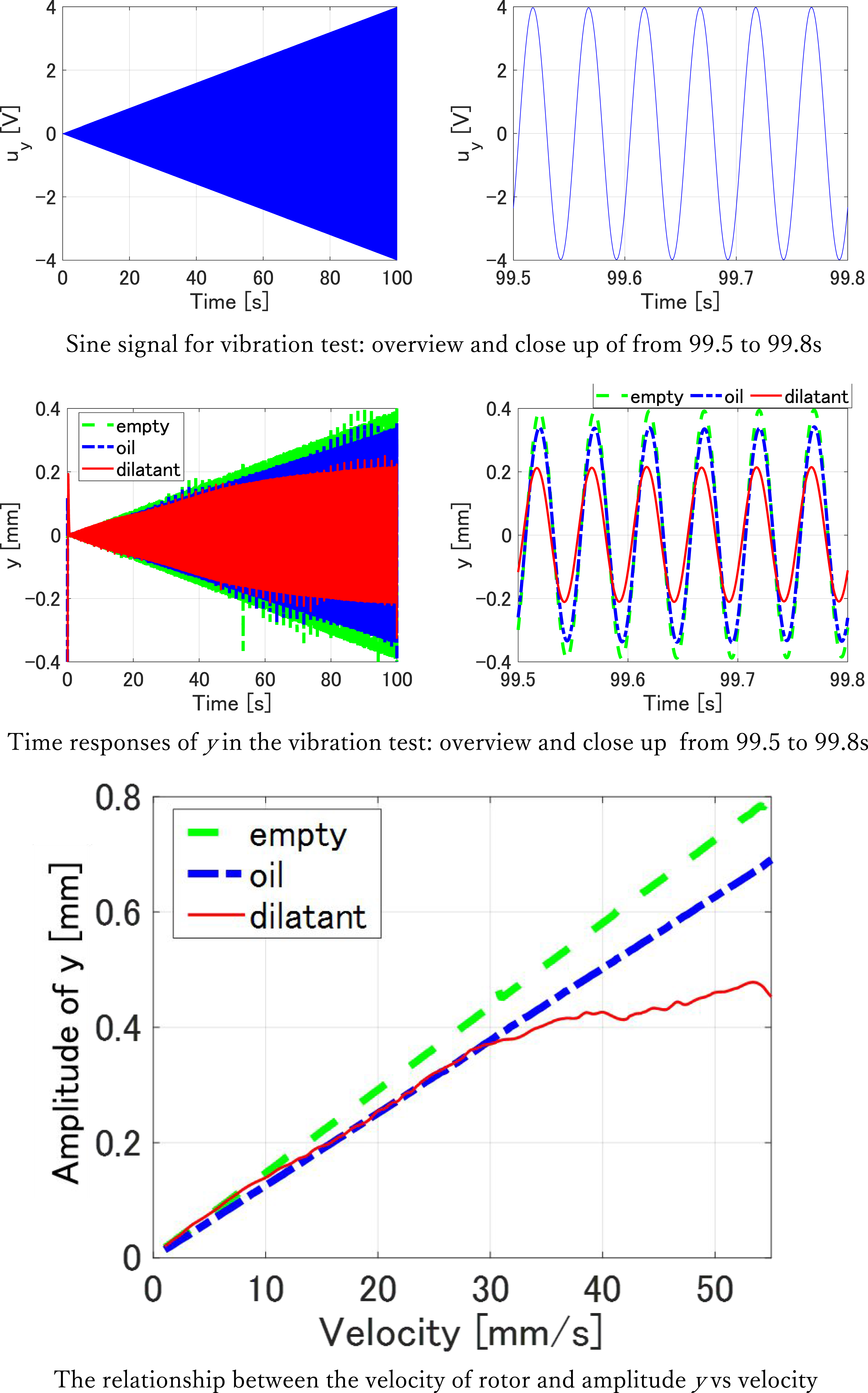
6. Conclusion
In this study, the objective was to develop a model of dilatant fluids for the application of SFD and elucidate the rotor dynamic coefficients. The rotor dynamic coefficients obtained in this study effectively represent the characteristics of the sharp viscosity increase of dilatant fluids. Furthermore, through a comparison with oil, it became evident that by using dilatant fluids in SFD, it is possible to achieve an SFD system that allows the normal operation of machines without hindering their movement, while suppressing abnormal vibrations when they occur. This is supported by the observation that when the axial rotational speed is low, the coefficients C and K of the dilatant fluid are smaller than those of oil, whereas at high rotational speeds, the coefficients C and K of the dilatant fluid are larger than those of the oil. In addition, to determine the rotor dynamic coefficients of highly nonlinear dilatant fluids, a relationship equation was derived between the fluid-generating force under constant-velocity conditions and the conventional model equation for calculating the rotor dynamic coefficients by including the constant velocity condition.
In this study, experiments were conducted with a dilatant fluid consisting of water and corn starch mixed at a weight ratio of 1:1.05, using an SFD system with a clearance of 2 mm. However, conducting experiments under different conditions would provide a deeper understanding of SFDs using dilatant fluids. For example, reducing the clearance would result in higher shear rates, even at the same excitation velocity, leading to faster observation of shear thickening. By conducting experiments with various clearances, the dependence of the characteristics on the clearance as a parameter can be elucidated. Furthermore, the concentration of dilatant fluid in this study significantly influenced the characteristics of SFD. Even with the same clearance, the time at which the thickening behavior occurs can be influenced by varying the concentration, which can be beneficial for predicting the dynamic properties during the design phase. In addition, dilatant fluids can be produced not only with water and corn starch, but also with corn starch or microplastics. Therefore, differences in dilatant fluids based on the choice of materials could also be the subject of future studies.
Although it has not yet been put to practical use, the phenomenon in which viscosity increases when a sudden external force is applied should be useful in designing novel mechanical systems. In this research, we have focused on rotating machinery and modeled its dynamic characteristics, and it will be helpful to employ the dilatant fluid for the rotating machineries.
Footnotes
Declaration of conflicting interests
The author(s) declared no potential conflicts of interest with respect to the research, authorship, and/or publication of this article.
Funding
The author(s) received no financial support for the research, authorship, and/or publication of this article.