
Abstract
In this paper, a new passive mechanical structure, that is, an X-structured wave energy conversion system with a nonlinear inerter is proposed. The JONSWAP wave spectrum is utilized to simulate irregular waves, and the dynamic equations are deduced by the energy method and one-dimensional linear potential wave theory. The system response is calculated to analyze the performance of the nonlinear system. The potential benefits of nonlinear inerter are discussed in-depth. Increased inertance will result in a gradual decrease in resonance frequency. Whereas, when the inertance is larger than a certain limit value, the resonance frequency will be almost unchanged. Additionally, increasing the inertance helps to suppress the displacement and velocity of the system. This allows higher power to be captured without causing major damage to the mechanical structure of the system. More importantly, increasing inertance is conducive to improving the maximum power generated. In general, a nonlinear WEC system will capture more power than its linear counterpart and the case with no inerter, especially when with a small initial installation parameter. However, when the initial installation parameter becomes large, the nonlinear inerter system will capture less power than the linear inerter system and inerter-free system. This study provides innovative and novel insight into designing nonlinear ocean energy converters exploiting geometrical nonlinearities.
Keywords
Highlights
• A novel nonlinear-inerter-based X-structured ocean energy converter is for the first time proposed. • The power generation with nonlinear inerters outperforms its linear counterpart and the case with no inerter. • The initial installation parameter of the X-structure would also play an important role, for both the cases with and without nonlinear inerter. • This study provides innovative and novel insight into designing nonlinear ocean energy converters exploiting geometrical nonlinearities.
1. Introduction
Wave energy is considered a sustainable power source due to its reliability, consistent availability, and abundant reserves (Gardner, 2015). The wave energy technology has been explored for many years and significant results have been achieved (Clement et al., 2002; Gunn and Stock-Williams, 2012). For wave energy converters (WECs) (Guo and Ringwood, 2021), thousands of models and theories have been proposed, including oscillating water columns, overtopping devices, and oscillating body wave energy converters (Zhang et al., 2022). Oscillating bodies, also known as point absorbers, show great promise as wave energy converters, particularly for offshore locations (Falcão, 2010).
In linear WEC systems, the converted power is typically low under non-resonant conditions, as real sea states do not conform to regular wave patterns (Zhao et al., 2023). This means that WEC and power-take-off (PTO) systems may not consistently reach their optimal operating conditions or resonate effectively. Consequently, researchers are exploring potential solutions to enhance the power capture performance of the oscillator WEC, including control methods (Paparella and Ringwood, 2016), hybrid approaches (Zhao et al., 2019), shape optimization (Shadmani et al., 2024), and PTO enhancement (Zou et al., 2019). Differently, this paper focuses on point absorbers to study how inerter nonlinearities improve their power performance.
Nonlinearities can greatly enhance vibrating systems in several ways (Fang et al., 2023; Yang et al., 2024). They can decrease resonant frequency without compromising load capacity (Yan et al., 2022), reduce resonant peaks while maintaining high-frequency vibration (Ding and Chen, 2019), and expand the frequency range of vibration suppression (Ibrahim, 2008). Utilizing these nonlinear characteristics can also greatly enhance the efficiency of energy harvesting (Tran et al., 2018). The X-structure/mechanism approach (Jing, 2022) has been proposed as a novel nonlinear mechanism, which drew inspiration from the skeletal systems of animals, and offers a dependable and versatile solution for applications that demand exceptional nonlinear stiffness and damping characteristics. In the realm of wave energy harvesting, X-structure devices may also have good potential when exploiting their nonlinearities.
Inerter is a passive mechanical component that consists of two nodes with distinct properties. Its terminals are directly proportional to the relative acceleration between them when a force is applied to them (Smith, 2020). A ratio known as inertance in kilograms is defined to express this proportionality. Through proper design, the inertance of an inerter can greatly surpass its actual weight (Zhang et al., 2019). Integrating inerter into X-structures may establish inertial coupling, thereby maximizing vibration transfer for optimal performance. However, the theoretical research on combining the excellent properties of the inerter to reduce the system’s natural frequency and regulate the system’s displacement and velocity with WEC systems is still very limited.
Although nonlinear stiffness mechanisms have been explored in some studies of nonlinear WEC systems, they are still rather simple in structure and do not take advantage of the X-structures in wave energy harvesting. Importantly, to the authors’ best knowledge, very few studies on WECs have been reported in terms of the nonlinear inerter mechanism. This makes the results of previous studies somewhat inadequate both in terms of power captured and frequency range. These are the main motivations of our present work.
In this paper, a new double-layer X-structure WEC system with an inerter, a spring, and an electromechanical harvester has been proposed. The X-structure within the system is specially designed, which could generate geometrically non-linearities (although the spring, the inerter, and the electromechanical harvester are all linear devices), especially the geometrically nonlinear inerter. It should be noted that the nonlinear inerter has the advantage of regulating the natural frequency of the system, limiting displacement and velocity of the floater, and increasing the power captured by the system. Comparing linear inerter and inerter-less situations, we found that, the nonlinear inerter solution is more advantageous, especially for the low-frequency case (i.e., irregular wave peak frequency is lower than the system resonance frequency).
The rest of the paper is organized as follows. The designs of the inerter-type nonlinear WEC system are presented in Section 2. In Section 3, dynamic modelings for the proposed system are obtained by using the JONSWAP spectrum and energy methods. In Section 4, system responses are calculated, and the nonlinear characteristics of the system are discussed in depth by comparing different parameters. Afterwards, conclusions are drawn in Section 5.
2. The proposed nonlinear inerter-type X-shaped wave energy converter
The X-structure-based wave energy harvesting system with geometrically nonlinear inerter arrangement is proposed. In this case, a linear inerter device is placed horizontally within the X-shaped structure, to trigger geometrically nonlinear property, as shown in Figure 1(a). To make comparisons, in Figure 1(b), a linear inerter device is placed vertically within the X-shaped structure. Compared with the horizontal one, it can be regarded as the counterpart linear case, that is, linear inerter arrangement. The inerter-type X-shaped ocean energy conversion systems: (a) Nonlinear inerter arrangement, (b) linear inerter arrangement.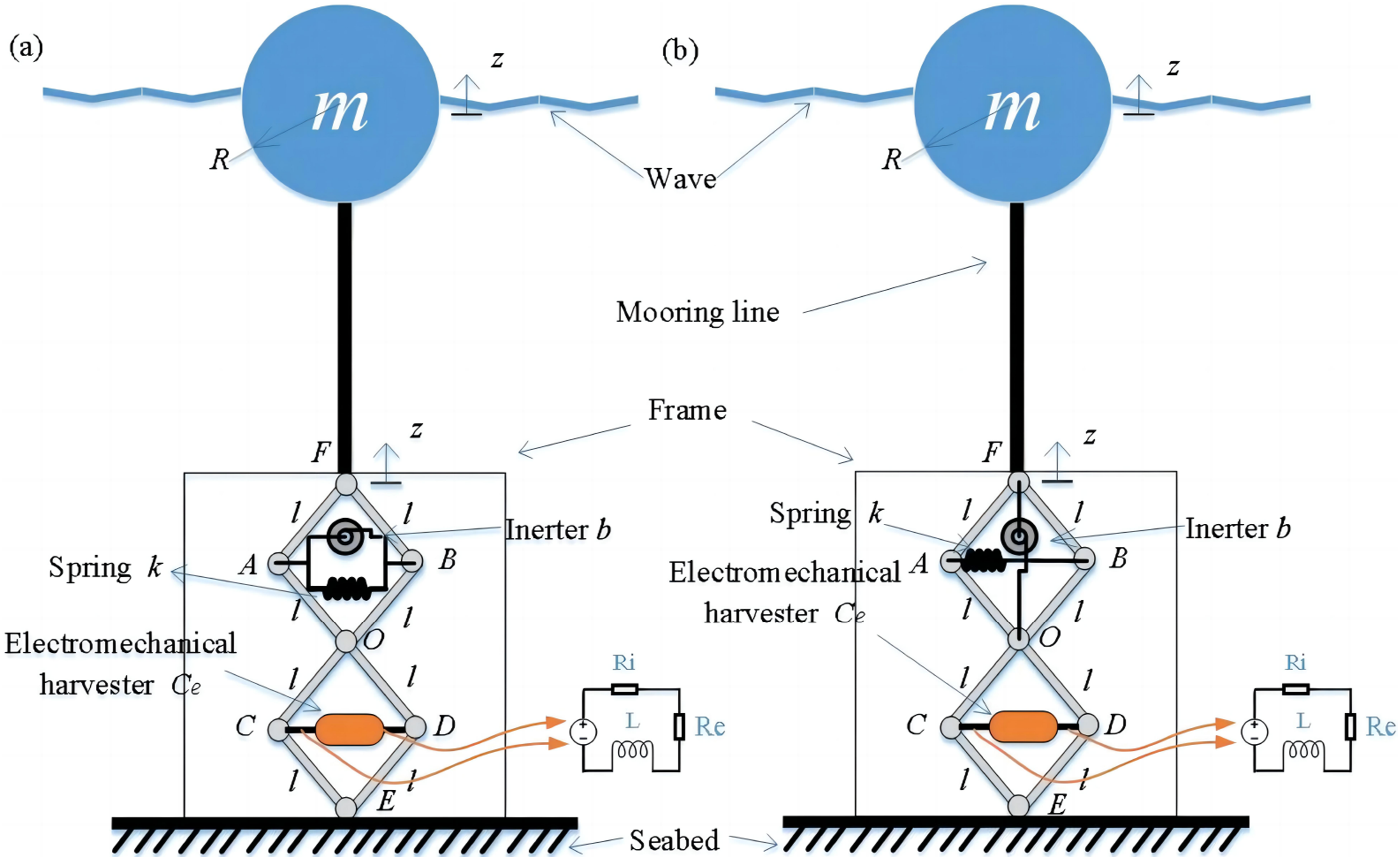
The buoy on the water’s surface is a solid sphere with a uniform mass distribution that rises and falls with the wave motion. The mass of the sphere is
The electrical power generation through the corresponding electromechanical harvester is regarded as the power created. Its damping coefficient is
In summary, the electromechanical coupling coefficient can be determined by the selection of the generator motor and the design of the gear transmission system. As a theoretical study, in this paper, a constant value of
The wave force will act directly on the buoy to drive the motion of the X-structure as well as the PTO system, as shown in Figure 2. Motion of the X-structure and PTO system driven by the wave.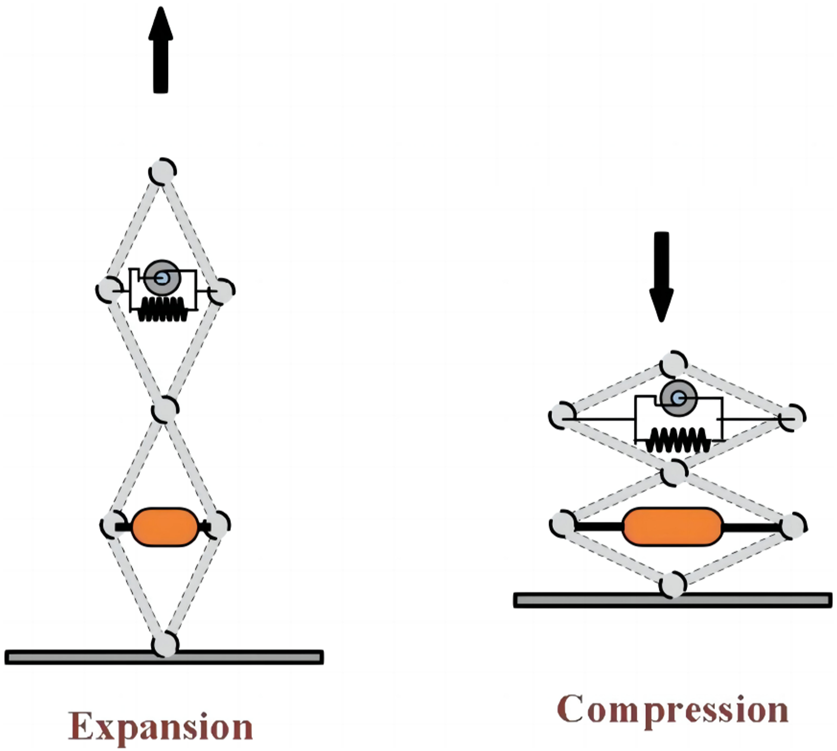
In this work, we concentrate on the wave energy converter’s dynamic reaction and power collection capabilities in irregular waves. Because spherical buoys exhibit axial symmetry, only the Buoy’s heave motion is taken into account for simplicity, and motion in the direction of other degrees of freedom is disregarded. Because of the axisymmetric nature of the spherical buoy, only irregular waves incident in one direction are considered. It is also assumed that the water’s depth is unlimited.
3. Dynamic modeling of the inerter-type X-shaped wave energy converter
In this section, some geometric relationships are used to derive links between some key variables and then we use the Lagrange method to derive the dynamical equations of the structure. Irregular waves are generated by the superposition of numerous regular waves based on the rules of the JONSWAP spectrum. Also, the wave loads are divided into three components, which are added to the dynamic equations of the WEC system after obtaining their expressions separately. With these three steps, the dynamical equations of the inerter-type X-shaped WEC system can be fully obtained.
3.1. Dynamical equations of the inerter-type X-shaped WEC system
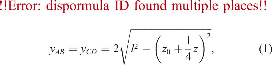
Note that the triangles The geometric relationships within X-structure.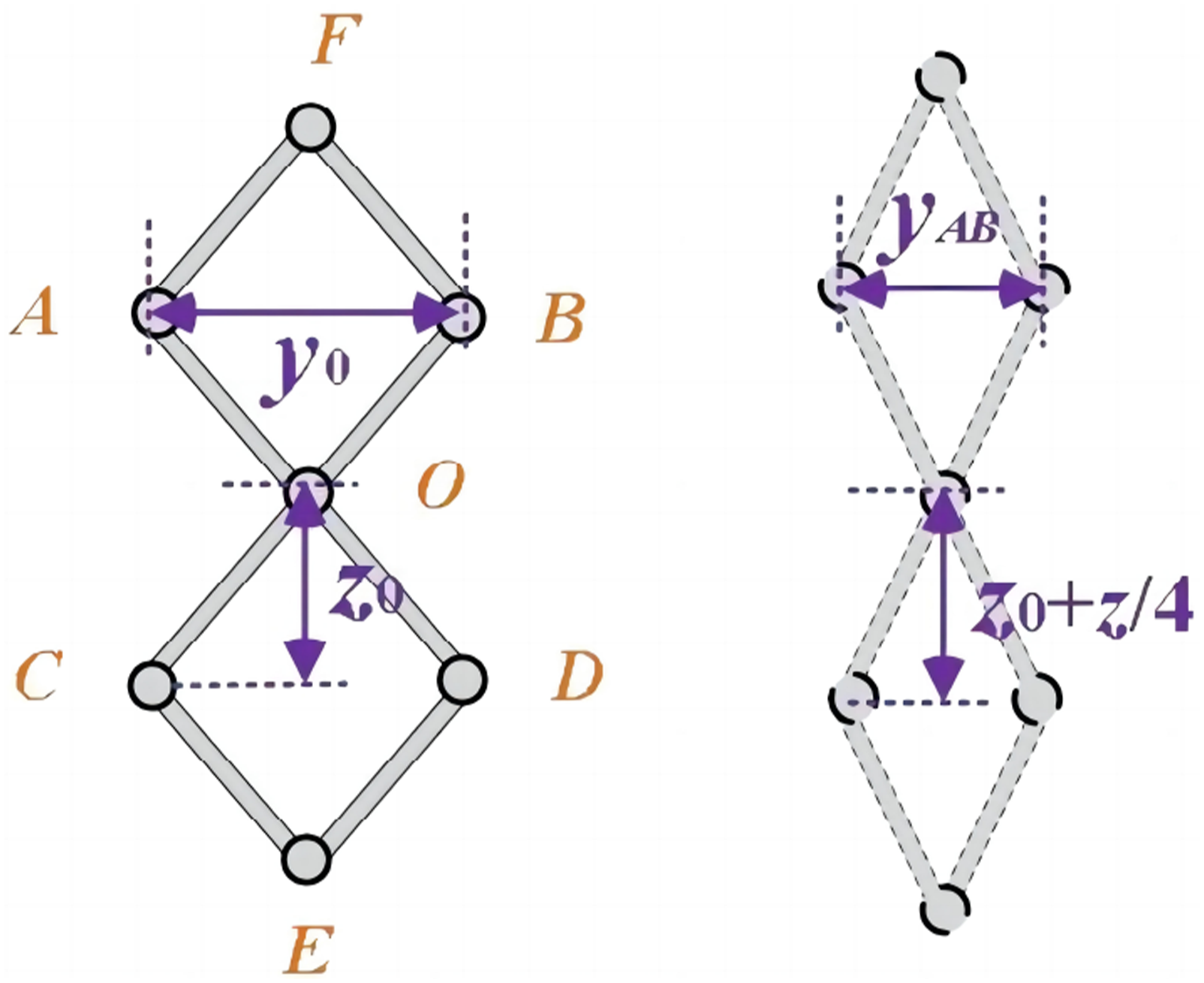
Based on geometric relationships, we have (
3.1.1. Modeling of the horizontal inerter case
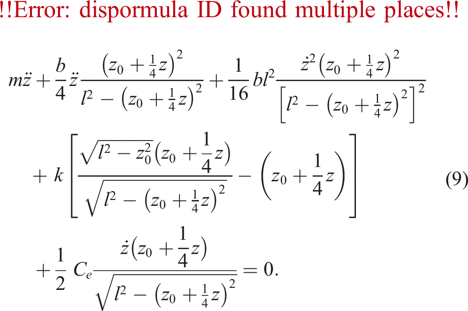
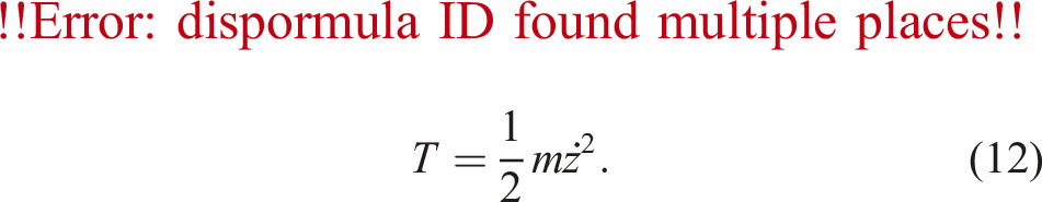
In Figure 1(a), the system’s kinetic energy is


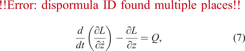
Substituting them into the Lagrange equation


3.1.2. Modeling of the vertical inerter case
In Figure 1(b), the system kinetic energy is

3.1.3. Modelling of the inerter-less case
For X-structure WEC systems with only spring and electromechanical damping, the system kinetic energy is transformed into
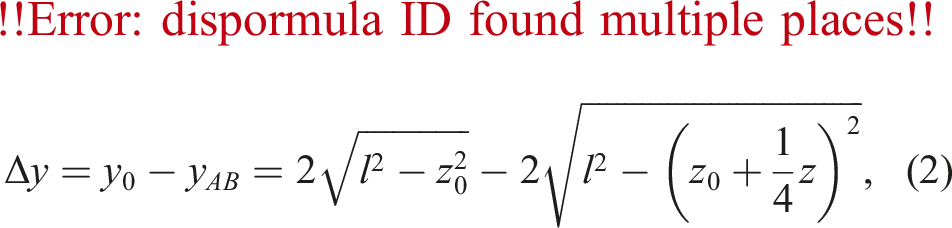
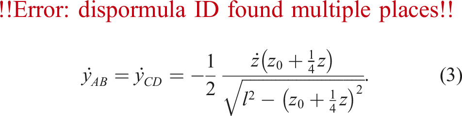
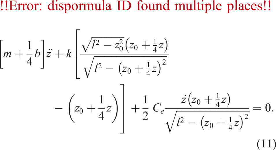
Given that the WEC system’s potential energy and non-potential force remain the same, the final result is
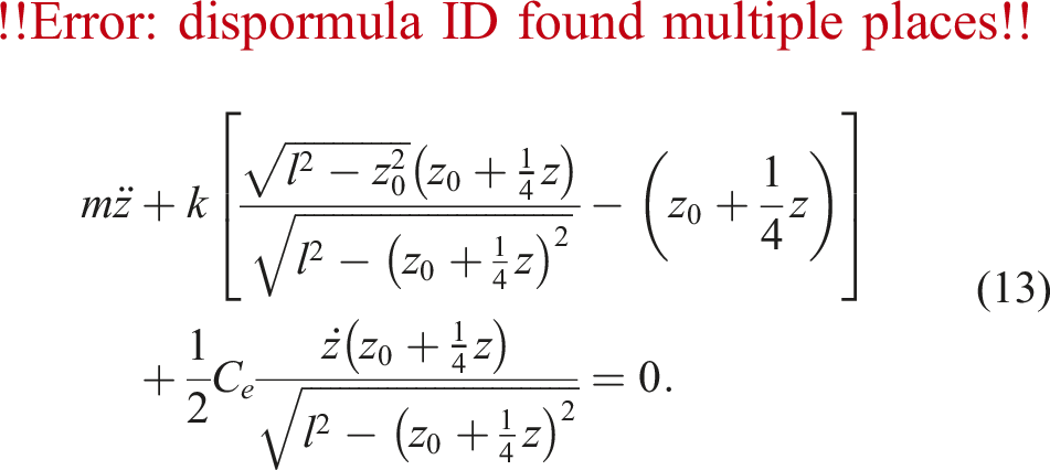
It should be mentioned that the above equation (equations (9), (11), and (13)) are the dynamical equation of the nonlinear X-structured inerter-type wave energy harvesting system without considering the wave force.
3.2. Descriptions of the wave forces
According to Nemoto et al. (Nemoto et al., 2022), the wave excitation can be divided into three parts, the excitation force
3.2.1. Hydro-static force
Regarding the buoyancy of the spherical buoy, it is specified that in equilibrium without any excitation, the draft line of the sphere passes through the center of the ball. Since the displacement of the buoy is much smaller than its radius, that is,


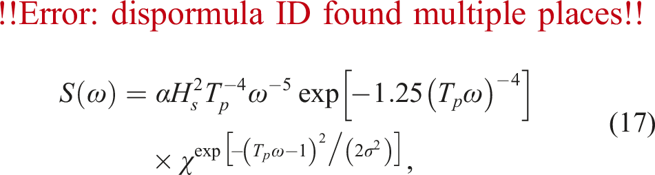
3.2.2. Wave excitation force
The real-world random wave response can be approximated as a superposition of multiple regular wave components. In this paper, the JONSWAP spectrum is utilized to simulate the irregular wave condition. The JONSWAP spectrum is expressed as (Hasselmann et al., 1973)
A range of circular frequencies is needed to produce irregular waves with the JONSWAP spectrum. We define

The formula for the amplitude of the nth regular wave component is given by Zhang and Yang (2015), shown as below

Theoretically, the wave excitation force caused by irregular waves can be superimposed by the wave excitation forces caused by countless regular waves with infinitely small amplitudes (Zhang et al., 2014). For the wave model in this paper, only the radiation potential and the incident potential in one direction need to be considered. The wave excitation force modulus
The above equation is also known as the Haskind relationship (Haskind, 1958), where
After obtaining the radiative damping coefficients generated during the oscillation of the floating body, the excitation force induced by the countless regular waves is summed up, and an expression for the excitation force is finally obtained as

3.2.3. Wave radiation force
The magnitude of the wave radiative force depends on a kernel function of the heave oscillations and a radiative drag coefficient, which, according to Cummins (1962), can be expressed in the form of convolution integral as
Nevertheless, the analysis of the nonlinear issue is computationally demanding and difficult if the convolution integral is computed in the time domain. Different techniques can be used to estimate the convolution integral in order to prevent such issues.
Ogilvie (1964) determined the links between the time domain and frequency domain model parameters using the Fourier transform, which are listed in Appendix A.
In this case, the kernel function is transformed by the Fourier transform into
According to Zhang and Yang (2015), the final form of the radiative force can be expressed by the state-space equation
Obtaining the transfer function of the system by Laplace transforms
It’s worth noting that equation (28) is accurate only when the order of the system tends to infinity.
Restricting
When using the iterative method to obtain the coefficient matrices
3.3. Ultimate dynamic equations of the conversion system
Finally, equations (9), (11), and (13) can be updated and written as follows, using the state space equations to construct the convolution integrals and accounting for the hydro-static and excitation forces. The initial conditions chosen for this paper can be found in Appendix B.
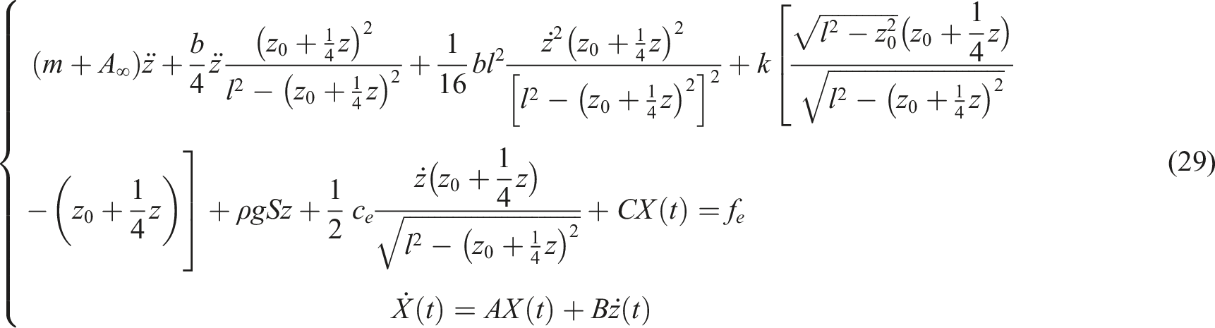
(1) Non-linear inerter arrangement:
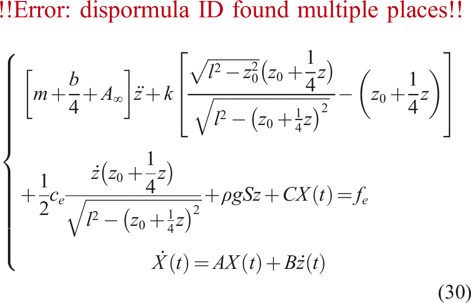
(2) Linear inerter arrangement:
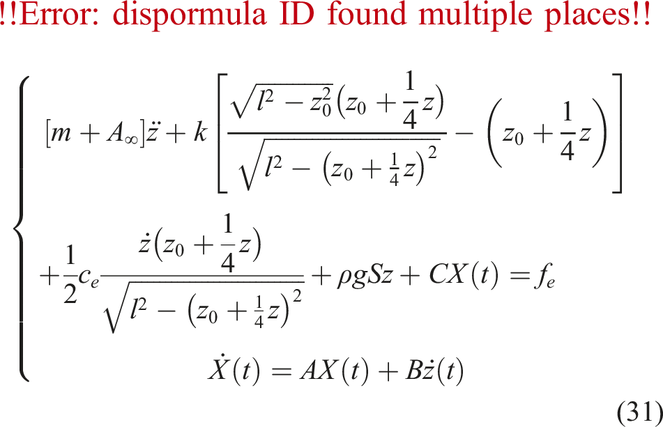
(3) Inerter-less model:
4. Results and discussions
For the above-proposed system of nonlinear differential equations, in this paper, we use the adaptive 4th-order Runge–Kutta method with transformable step size to solve the equations. After obtaining the displacement
4.1. Predicted power generation
Initial conditions are selected, and calculation time is set from 0 to
The displacement, velocity, and acceleration of the lifting and sinking motion are obtained, as shown in Figure 4. Buoy displacement and velocity over time: (a) Displacement over time, (b) velocity over time.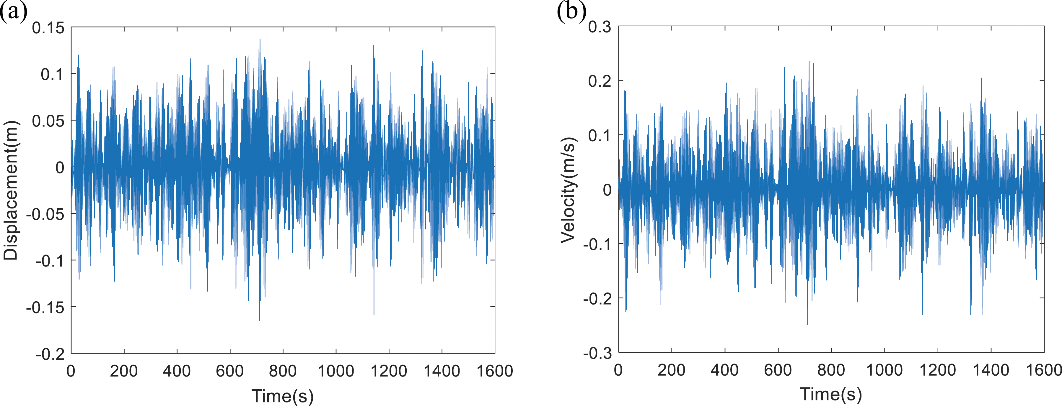
First, we define an initial installation parameter as the ratio of the initial distance (equilibrium position) of

Time-average power can be expressed as
Also, instantaneous power is

The instantaneous power can be obtained, as shown in Figure 5. As seen in the figure, the system can reach a maximum instantaneous power of 14 kW, and the average power can be up to 1208 W, which is not even the limit of the system’s performance when it reaches resonance. Instantaneous power and average power (in order to eliminate the power instability caused by the transient effects of the system, the captured power generated in the first 100 seconds is ignored in the calculation).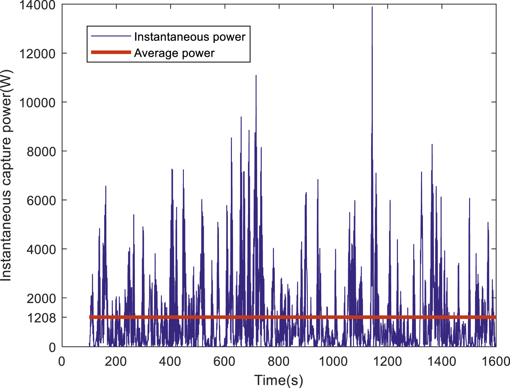
4.2. Effect of inerter on average power
The inerter, as an inertial element attached within the X-structure, mainly affects the coefficients of
To assess the impact of the inertance on the system’s collected power, an appropriate interval for the value of Effect of inertance 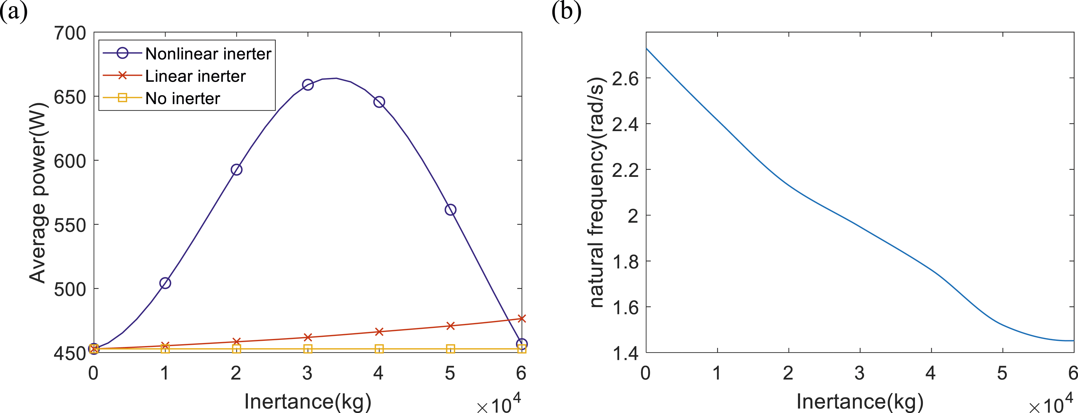
The inerter can adjust the natural frequency of the system, and in actual sea conditions, the wave’s peak frequency will fluctuate continuously. Because of that, the tuned inerter WEC system can be used to follow the peak frequency with the change of the inertance by some control means, such as the static admittance control (Nemoto et al., 2022), the performance guaranteed control (Asai and Sugiura, 2021), and the maximum power point tracking algorithm (Han et al., 2022), to obtain a larger capture frequency.
When the peak frequency Effect of inertance on maximum average power (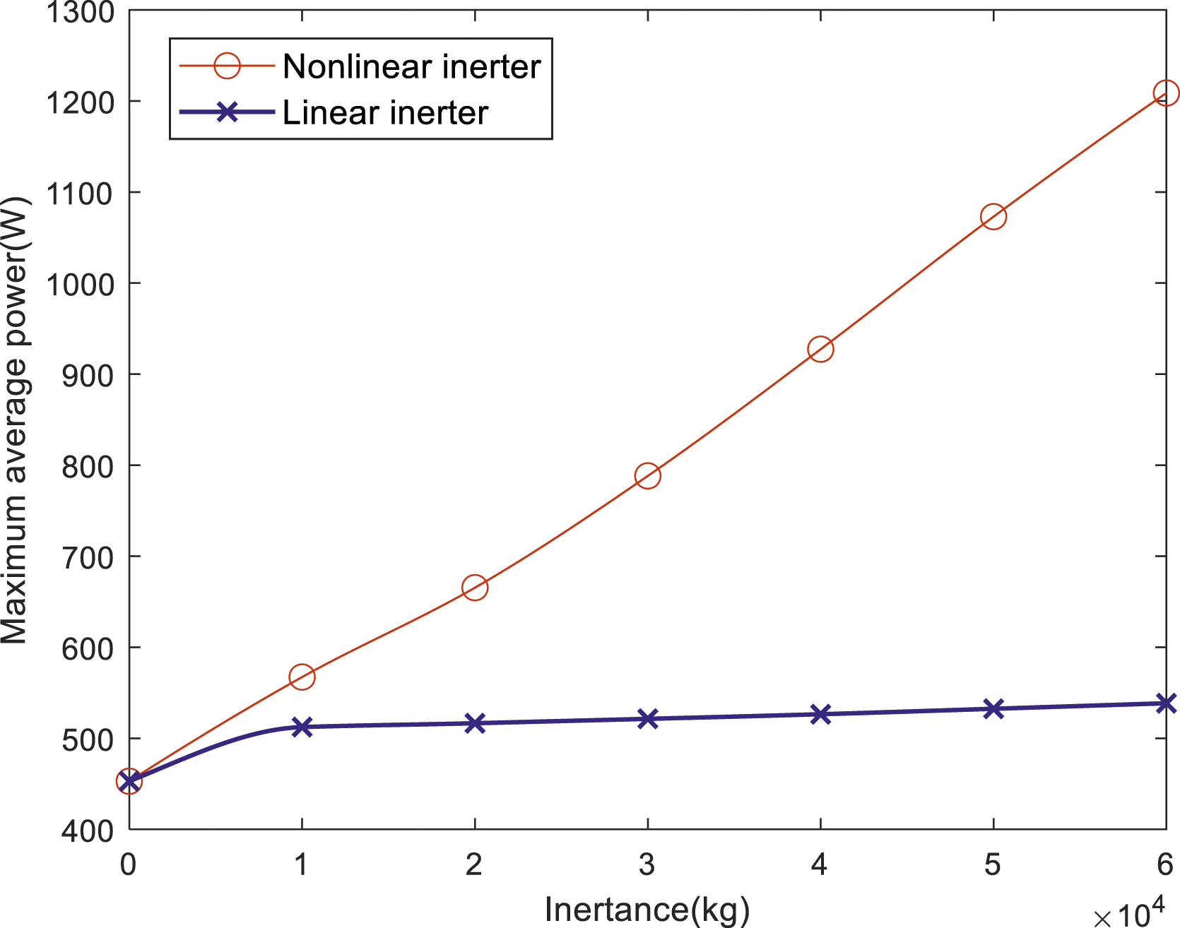
From Figure 8(a), for the nonlinear inerter design, it can be seen that increasing the inertance will lead to an decrease of resonance frequency of the system. Also, as the inertance increases, the average power generated at system resonance will increase, while the frequency range with higher values of captured power will become smaller. Effect of inertance on the power-frequency plot (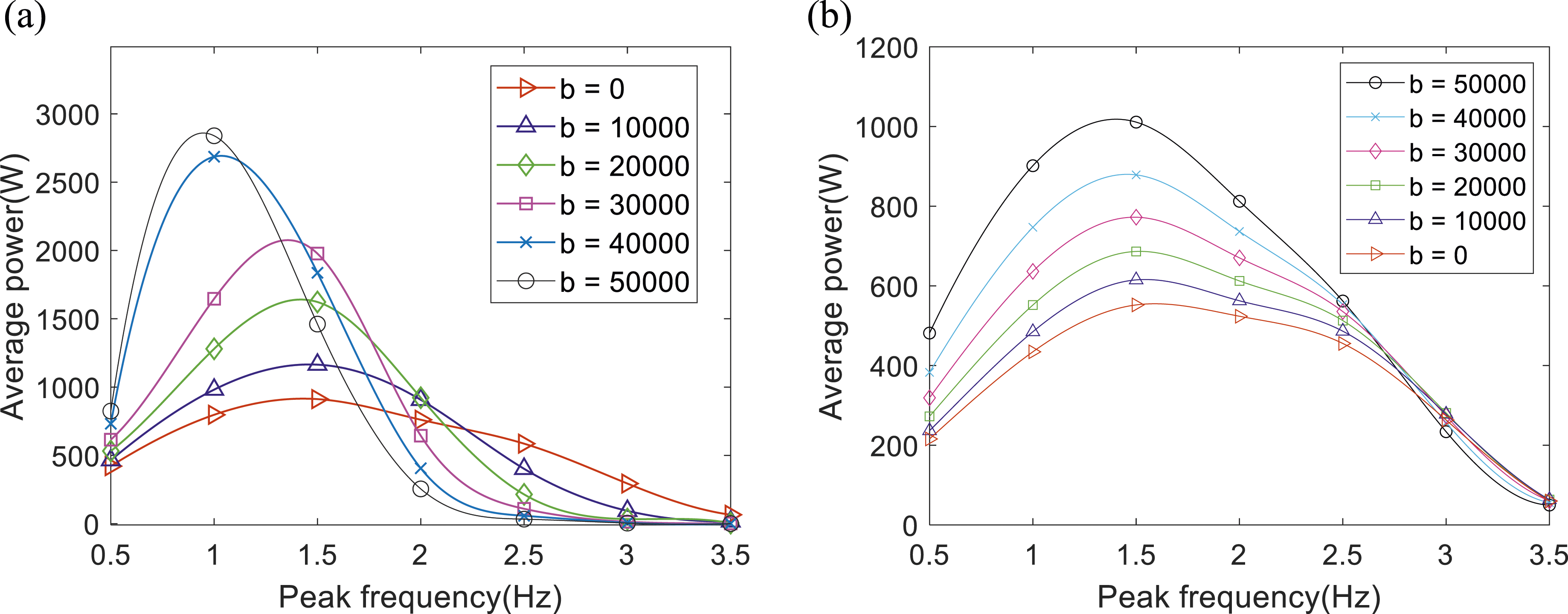
When
For the linear inerter system, as shown in Figure 8(b), the larger the inertance is, the larger the captured power is in the low-frequency range. However, when the peak frequency exceeds a certain value, a larger inertance will result in a smaller captured power instead.
4.3. Significant wave height’s impact on average power
In the JONSWAP spectrum, the square of the significant wave height corresponds to the amplitude of the regular wave components, as equations (19)–(21) have shown. On the other hand, a linear superposition of a series of regular wave components results in an irregular wave sequence, indicating that the linear WEC power achieved is proportional to the square of the effective wave height.
For oscillating WECs with nonlinear PTO systems, it could be much different. To verify it, Effect of significant wave height on average power (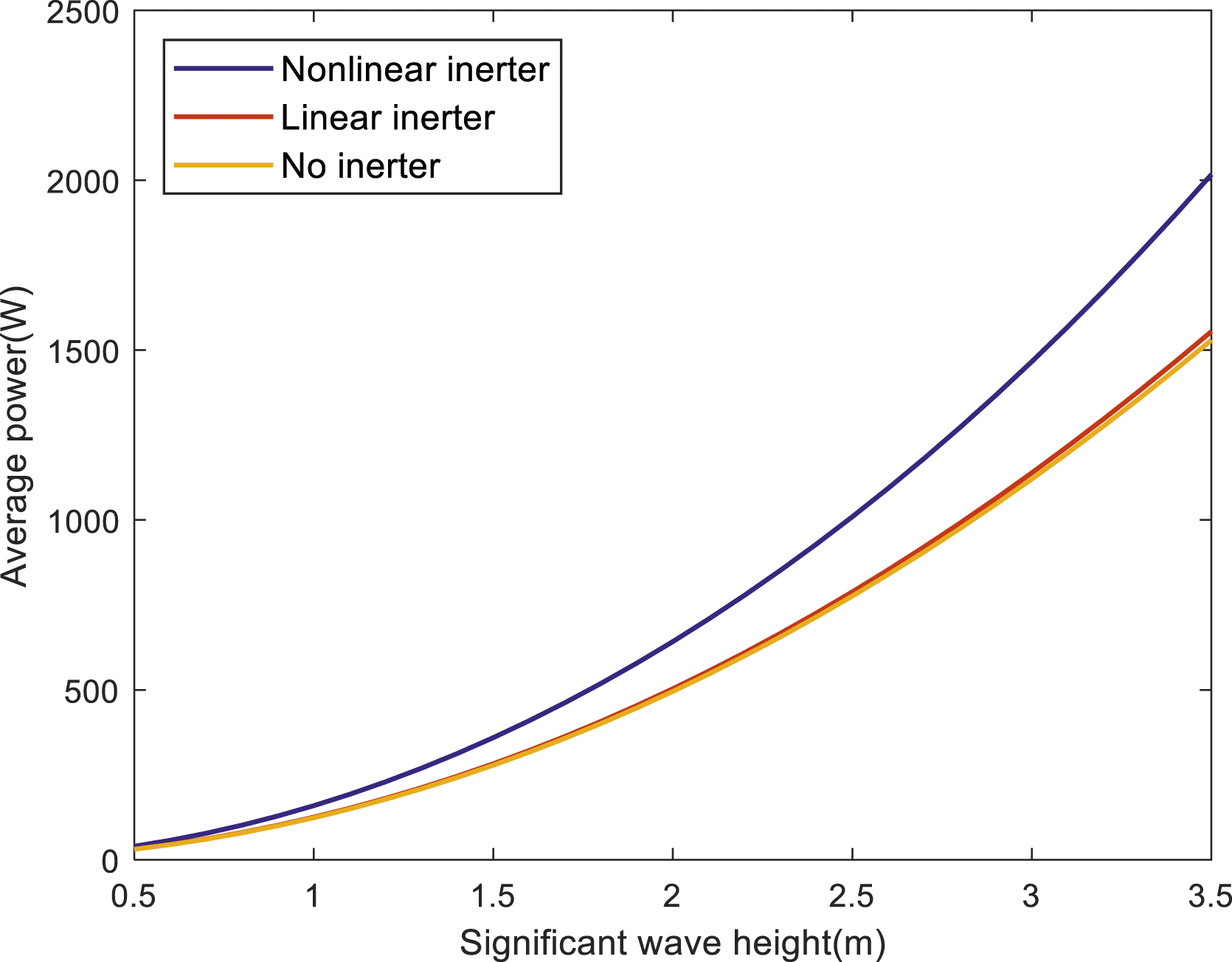
As can be seen from the figure, although the nonlinear inerter system has not yet reached resonance, its captured power is still larger than the other two. A nonlinear inerter wave energy converter system’s energy absorption is not directly proportional to the square of the significant wave height. Although a linear inerter WEC system captures more power than inerter-free system, the difference between the two is relatively small.
4.4. Effects of initial installation parameter on average power
In this subsection, the WEC system’s average power is assessed by taking
It is evident from Figure 10 that when the peak frequency and effective wave height are kept constant, the nonlinear WEC system can obtain a relatively high power with a smaller Average power versus initial installation parameter 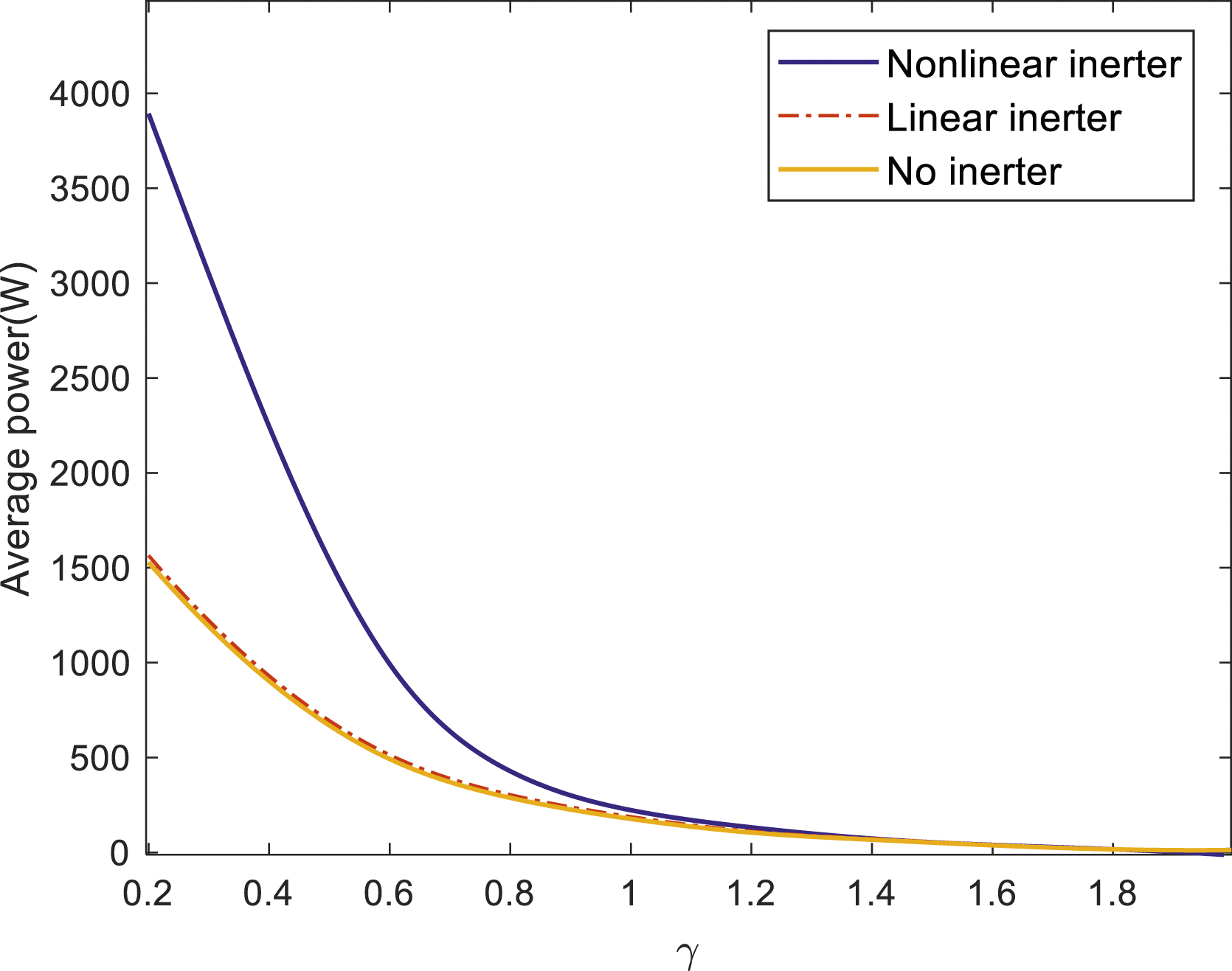
In addition, it is worth stating that when
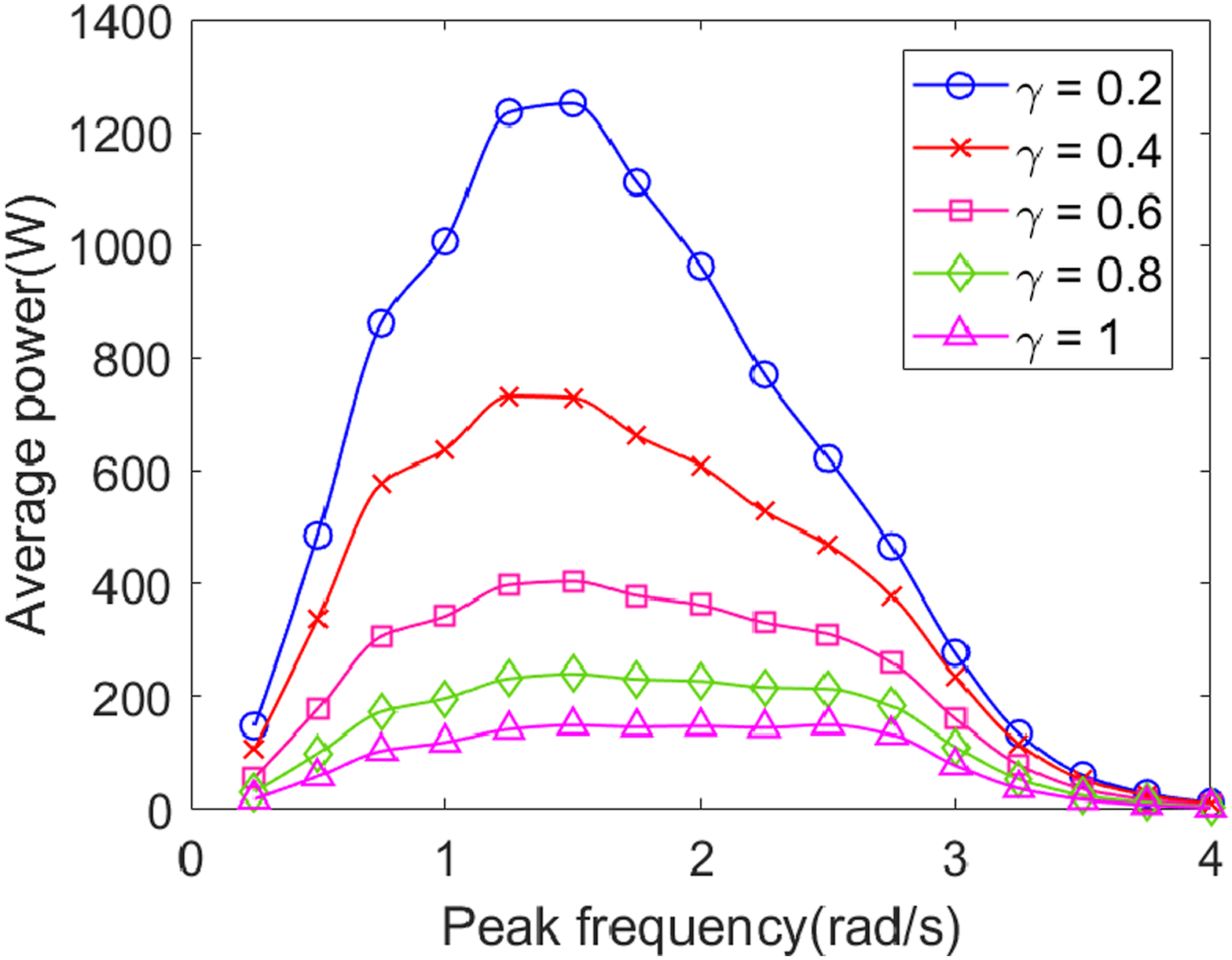
Taking the peak frequency Captured power versus peak frequency: Horizontal arrangement of inerter. Captured power versus peak frequency: Vertical arrangement of inerter. Captured power versus peak frequency: WEC system without inerter.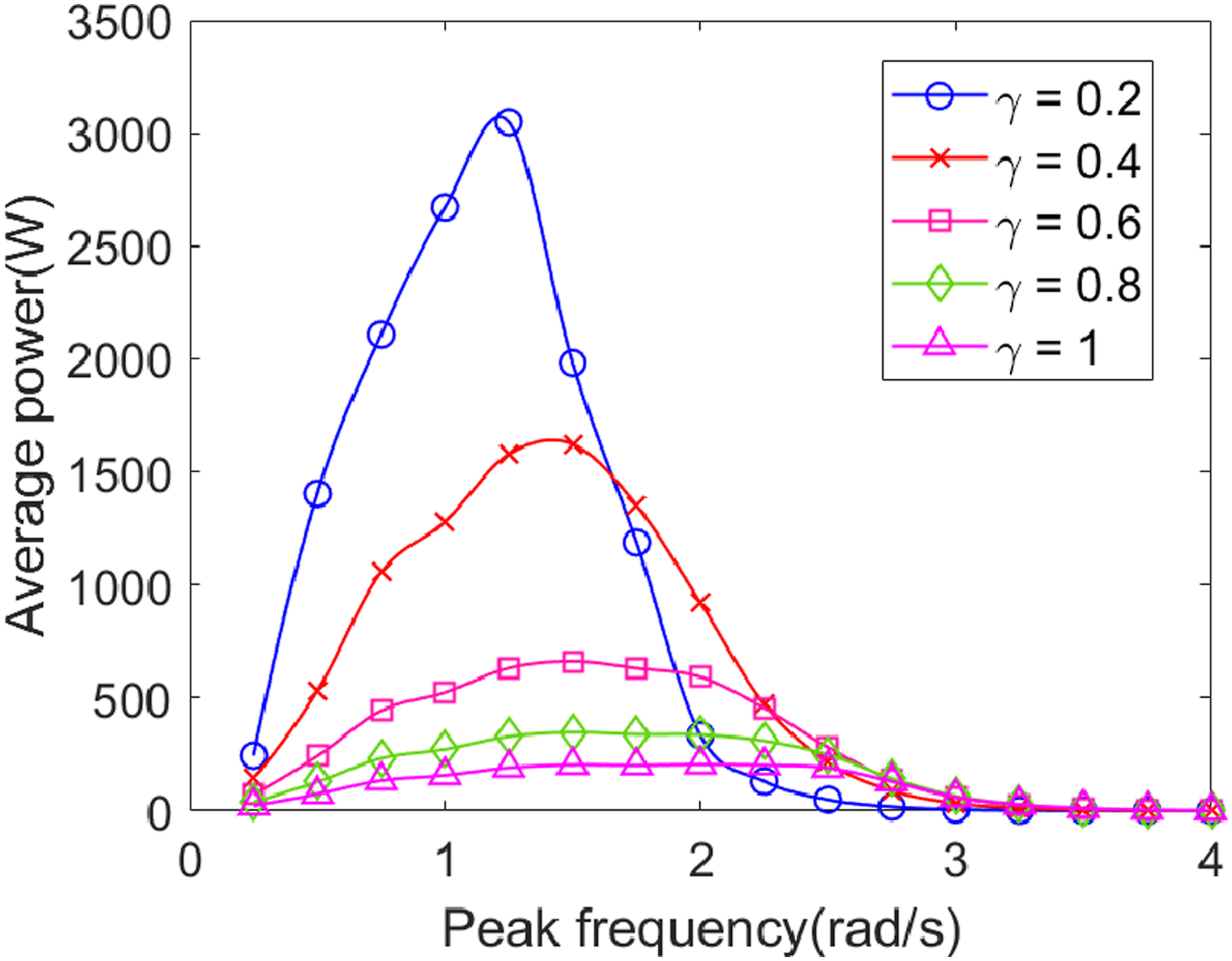
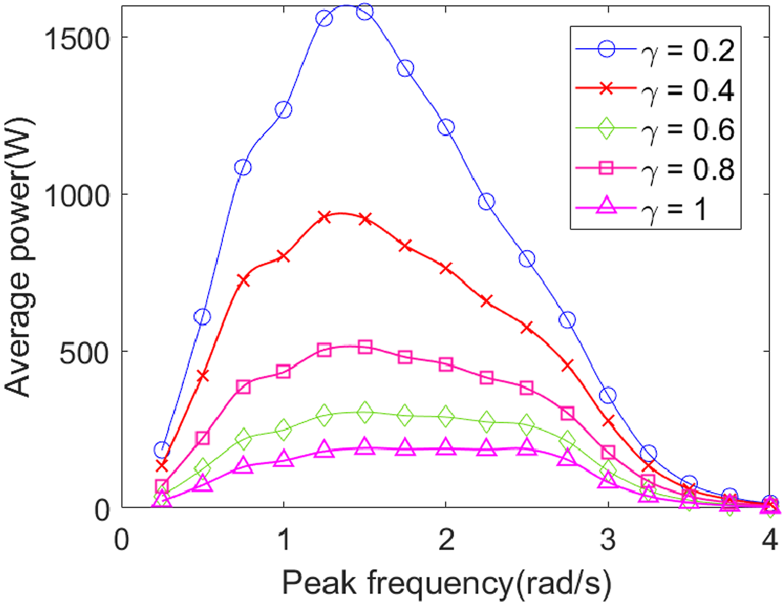
It has been known that, for WECs without an inerter, the resonant frequency of the WEC system varies significantly with the initial installation parameter
As shown in Figure 11, when the inerter is placed horizontally, in the low-frequency region (where the system’s resonance frequency is higher than the irregular waves’ peak frequency), the nonlinear WEC system captures more power with a smaller initial installation parameter
However, for systems where the inerter is placed vertically (Figure 12) and for systems without the inerter (Figure 13), regardless of how the peak frequency of the irregular waves varies, the system’s collected power increases with a smaller initial installation parameter
5. Conclusions
This study examines the oscillator WEC’s power capture capability in irregular waves, using a nonlinear inerter-type X-structure. First, we propose a new inerter enhanced X-shaped wave energy converter and then derive the dynamic equations of such structure using the JONSWAP spectrum and energy method. After solving the equations, the following inferences can be made in light of the numerical result. (a) Changing the value of inertance can adjust the natural frequency of the WEC system, which is particularly noticeable for systems with smaller (b) The power captured by the oscillator WEC with a nonlinear inerter-type X-structure reaches its maximum value when the peak frequency of the irregular wave approaches the nonlinear natural frequency of the WEC system. (c) An increase in the significant wave height (d) For the X-structured WEC systems with nonlinear inerters, in the low-frequency region (where the system’s resonance frequency is higher than the irregular waves’ peak frequency), nonlinear WEC systems capture more power with a relatively small initial installation parameter. While in the high-frequency region (when the irregular waves’ peak frequency exceeds the system’s resonance frequency), as initial installation parameter decreases, the captured power of the system will decrease rapidly and can even fall below the capture power of a linear system. Importantly, for the X-structured WEC systems with and without linear inerter, the smaller the
Footnotes
Acknowledgements
The authors would like to thank the anonymous reviewers and the editors for their relevant comments and useful suggestions.
Declaration of conflicting interests
The author(s) declared no potential conflicts of interest with respect to the research, authorship, and/or publication of this article.
Funding
The author(s) disclosed receipt of the following financial support for the research, authorship, and/or publication of this article: This research is supported by the National Natural Science Foundation of China (No. 12302025 and No. 12272323), the Natural Science Foundation of Sichuan Province of China (No. 2023NSFSC1294), the Fundamental Research Funds for the Central Universities (No. 2682023CX054), the International Postdoctoral Exchange Fellowship Program: Talent-Introduction Program (No. YJ20220310).