
Abstract
Due to high power density and low production cost, the development of decentralized electric drive systems featuring integrated design and control becomes hot trend. In this paper, a comprehensive investigation is presented to vibration and noise influence assessment for an In-wheel Reducer and Motor Drive System (IWRMDS) equipped with passenger cars under typical conditions. In addition to the theoretical analysis, a test bench is built to measure resonance and vibrio-acoustic responses of the electric drive system. The dynamic modeling of multi-degrees of freedom for the integrated system is established, and numerical analysis in time and frequency domain is carried out. On the other hand, experimental effort is made on transmission test platform. Bench test results are obtained and compared with numerical predications. The resonant vibrations and acoustic time-frequency responses are identified and the optimal design solution for improving NVH performance of the in-wheel electric drive system is provided.
Keywords
1. Introduction
In the fight against global climate issues, the development and industrialization of electric vehicles play a prominent role. Among various types of electric drive systems, the decentralized electric drives are the ultimate solution to automobile technology, because of compact design, high efficiency, and low-cost. For adaptation to the rapid development of electric vehicle technology, an integrated in-wheel electric drive system including high speed motor and planetary gear reducer is developed. For improving NVH performance of the drive system, so called In-Wheel Reducer and Motor Drive System (IWRMDS), the theoretical modeling, analysis and experimental verification are undertaken during the development process.
In the past two decades, multi-stage planetary gear systems are widely applied in power-spilt hybrid transmissions for vehicles and in speed increasers for wind turbines. A fully coupled dynamic modeling method is proposed by Wei et al. (2017), which applying a virtual equivalent shaft element on a two-stage planetary gear system to study the dynamic behavior and coupling characteristics in-depth. A planetary gear’s translational-torsional dynamic model is established by Kim et al. (2012), and the effects of time-varying mesh phasing and angles on dynamic responses are examined. A multi-body dynamic model of a multi-stage planetary gear system is established by Li et al. (2014), studying nonlinear influence of damping, meshing frequency, and backlash on its dynamics performance. A four-degree-of-freedom dynamic model for gears is established by Marques et al. (2016), counting for friction, damping, and time-varying mesh stiffness. Simulation and fault detection of a planetary gear drives, using a rigid-flexible coupling method and Multi-Body Flexible Dynamics are analyzed by Hao et al. (2017). Influence of input torque fluctuations on the gear system vibrations and load distribution is analyzed by Ryali and Talbot (2022), utilizing a derived gear dynamics model. Meshing parameters of two-stage planetary gear transmission are examined by Yang et al. (2021), employing ANSYS Workbench simulations to derive equivalent stress, strain, and deformation in the meshing of planetary gears. Sensitivity to excitation frequency and meshing errors are studied by Liu et al. (2022), applying a nonlinear dynamic model of the planetary gear system. A dynamic model of a planetary gear system including rolling bearings is proposed by Xu et al. (2023), analyzing the contact loads and system behavior. Impacts of time-varying mesh stiffness on planetary gear systems are evaluated by Yang et al. (2024), establishing a nonlinear dynamic model counting for translational-torsional coupling effects.
In most of the research on dynamic behaviors of planetary gear systems, single-stage planetary gear sets and relatively simple dynamic model are considered. Also, studies in dynamic characteristics of compound planetary gear systems are limited. In the present research, vibro-acoustic mechanism and NVH performance are investigated for the brand-new electric drive IWRMDS, in which two-stage compound planetary gears are employed. Bench tests are carried out for parametrically excited vibrations and vibro-acoustic properties in semi-anechoic chamber. The numerical predictions and test results are demonstrated and compared in discussion.
2. Principle and configuration of IWRMDS
Principle and configuration of the IWRMDS are shown in Figure 1, in which, the motor shaft is connected to the sun gear of the first stage planetary gears set. The first carrier is coupled with the sun gear of the second stage planetary gear set, driving the planetary gears and the second stage carrier. The second carrier transmits power to the wheel rim connecting via a spline to the hub flange. Then, a complete system is formed, in which the hub spindle, drum brake, motor, planetary gear sets, and bearings are integrated to reduce axial space and weight for the IWRMDS. This configuration is characterized of high integration, good lightweight, high power density and smooth torque output in electric drive systems. Principle and configuration of IWRMDS: (a) structure of the system and (b) principle of the system.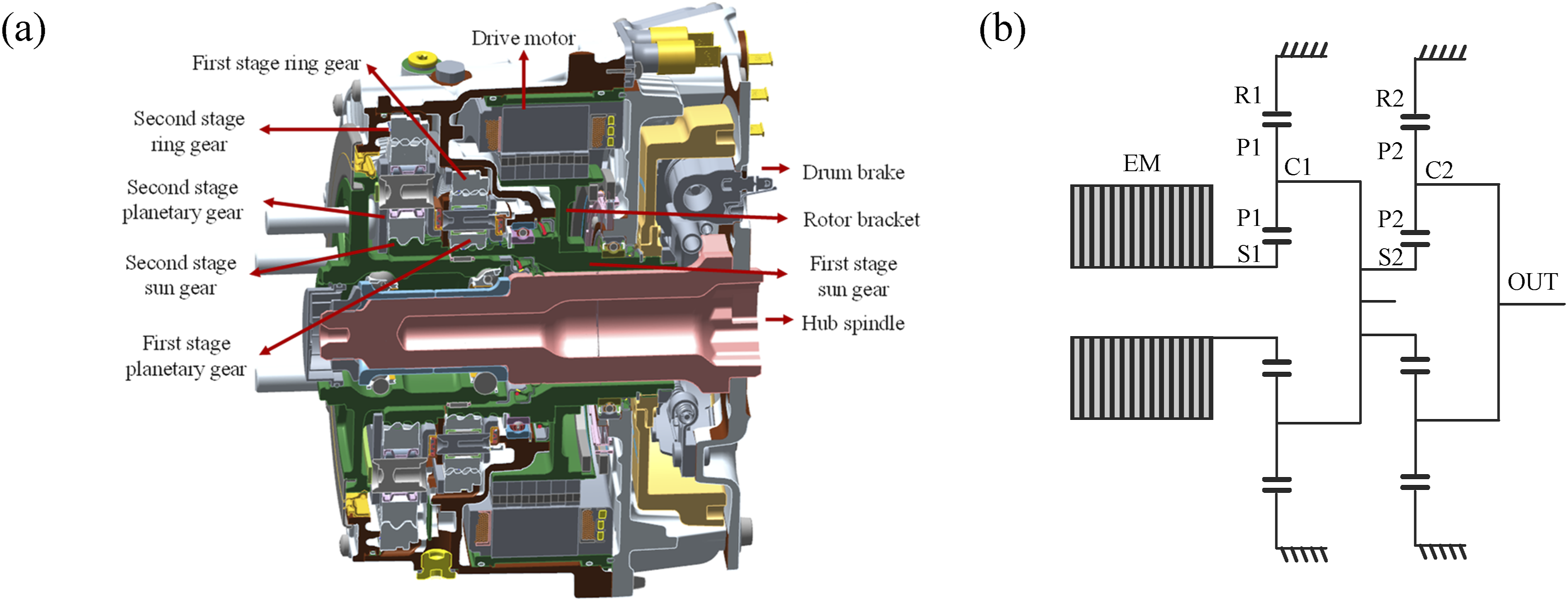
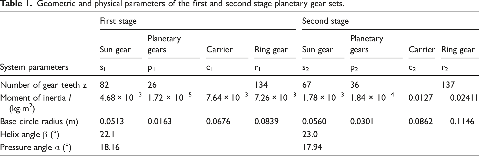
Before the dynamic modeling of the present drive system, some theoretical simplifications are required. For employing the lumped parameter method, the drive assembly is assumed to be a rotor-dynamic model of the two-stage planetary gear system. The lumped mass dynamic model for the two-stage planetary gear trains is shown in Figure 2, in which symbol subscripts m, c, r, s and w indicate motor, carrier, ring gear, sun gear and wheel hub, respectively. In Table 1, geometric and physical parameters of the first and the second planetary gear sets are presented. The lumped mass dynamic model for the two-stage planetary gear trains. Geometric and physical parameters of the first and second stage planetary gear sets.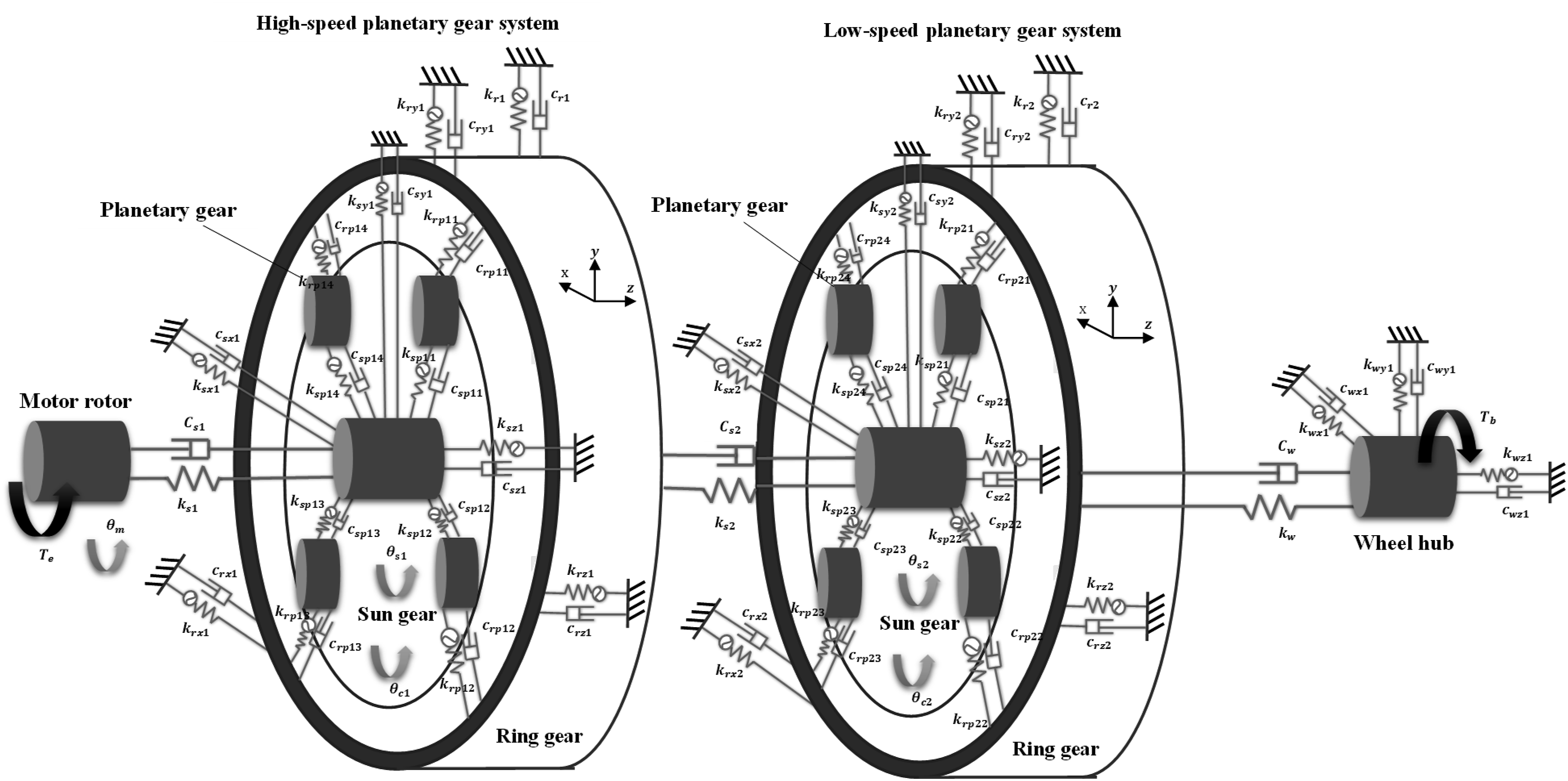
3. Dynamic modeling of the IWRMDS
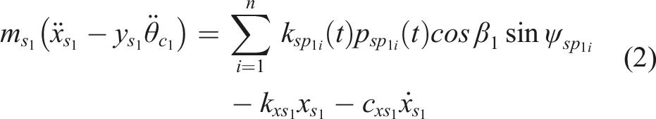
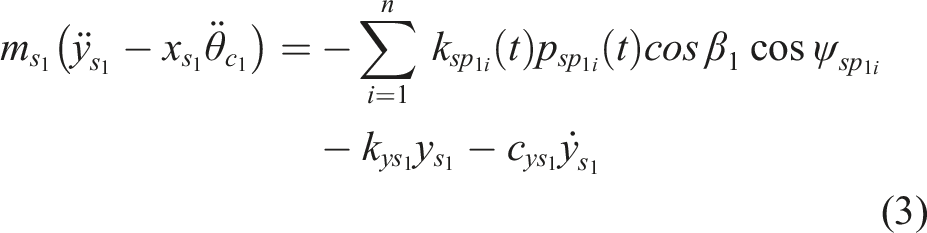
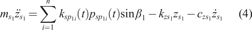
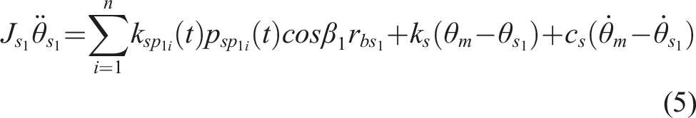
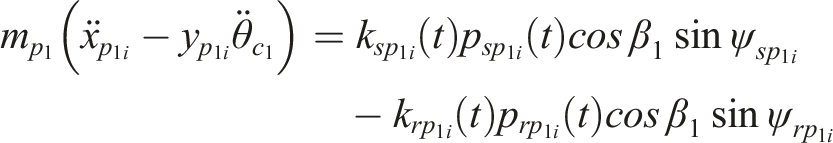
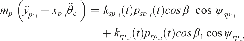
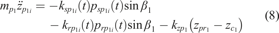
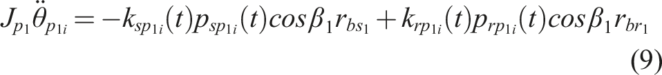
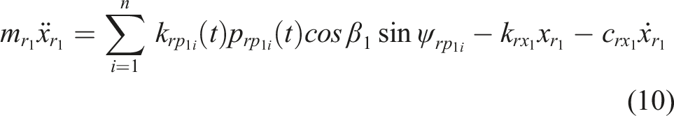
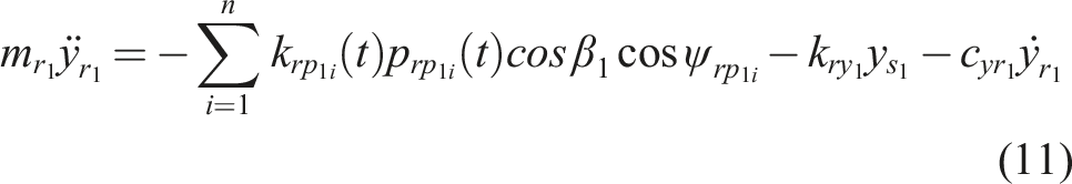
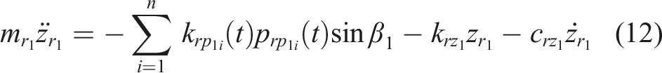
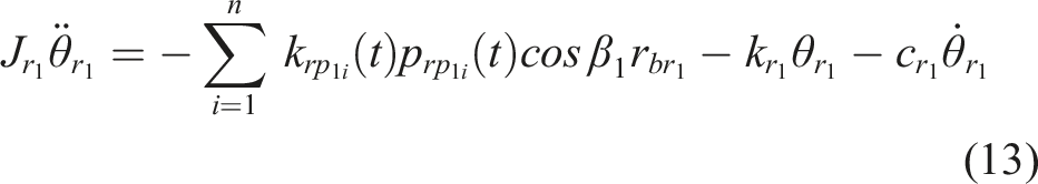
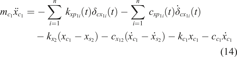
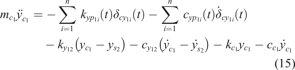
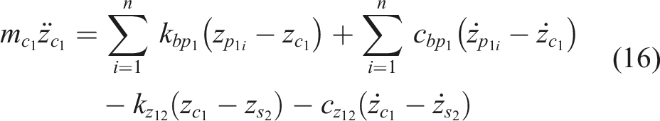
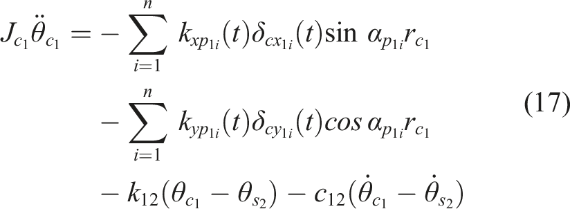
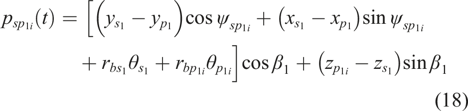
The dynamic model of the IWRMDS possesses of 61 degrees of freedom, which are related to x, y, z translations and rotation for the first sun gear, four planets, carrier, ring, the second sun gear, four planets, carrier, ring, wheel hub, and motor rotor. According to Newton’s mechanics, equilibrium equations of motion for the first stage planetary gear set can be expressed as follows:


4. Numerical analysis of the IWRMDS dynamic behaviors
Numerical solutions to the dynamic equations in (1)–(17) and equations (18)–(23) governing vibrations of the two-stage planetary gear trains for the vehicle in acceleration and deceleration conditions. Assuming the driving torque of the motor remains constant: for the driving condition, a torque of 200 Nm is applied by the motor to speed up from 0 to 6000 rpm within 30 s and for the driven condition, a torque of 100 Nm is applied by the motor in the opposite direction to speed down decrease from 6000 rpm to 0 within 30 s.
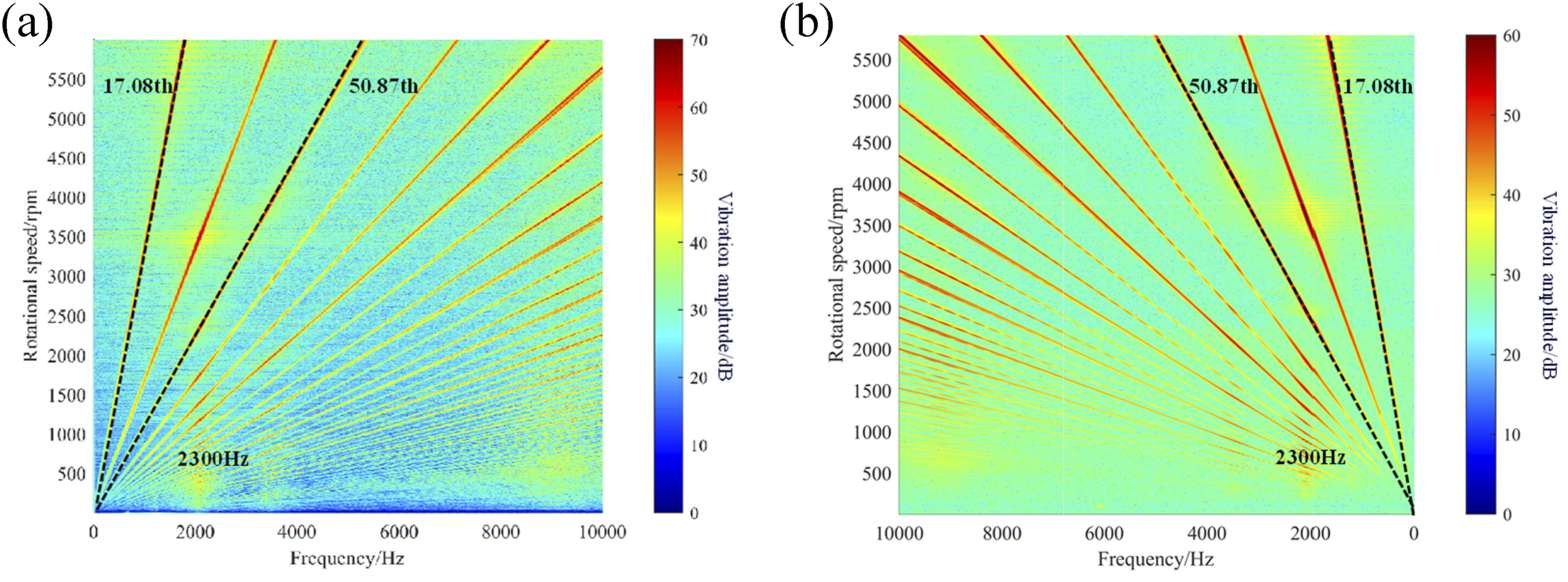
Numerical predictions for transient responses of vibration acceleration for the motor in time-domain are presented in Figure 3. As observed from Figure 3(a), it is evident that the resonance region is primarily concentrated between 17 and 18 s, where the motor speed is approximately 3500 rpm in the speed up process, and from Figure 3(b), the resonance region is primarily concentrated between 12 and 13 s, where the motor speed is approximately 3500 rpm in the speed down process. Significant fluctuations of the motor occur during the periods of acceleration or deceleration are illustrated after considering gear nonlinearities, the waterfall plots of dynamic responses for sound pressure of Figure 4, including the 50.87th of the first stage planetary gear system and the 17.08th of the second stage planetary gear system, as well as harmonic frequencies related to gear meshing. The time-domain and waterfall plots indicate that resonant vibration is particularly recognized around 2300 Hz, to occur at intersection points of the diagonal and perpendicular lines. Numerical results for transient responses for torsional vibration acceleration of the motor rotor: (a) while loading at torque 200 Nm in clockwise direction and (b) while loading at torque 100 Nm in counterclockwise direction. Numerical waterfall plots of dynamic responses for sound pressure measured 1 m away from the IWRMS: (a) while loading at torque 200 Nm in clockwise direction and (b) while loading at torque 100 Nm in counterclockwise direction.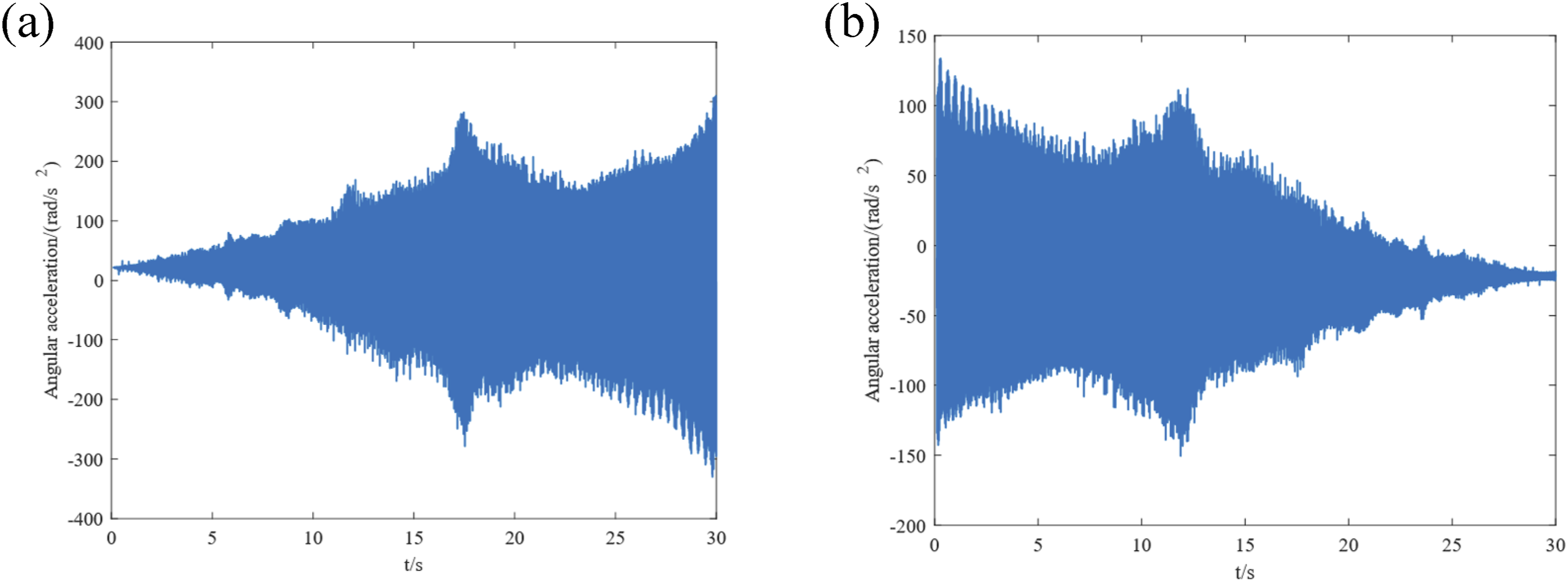
Simulation results for time-domain responses of torsional vibration acceleration are obtained and presented in Figure 5. The corresponding waterfall plots of dynamic responses for sound pressure of the second carrier are shown in Figure 6. Similar to the simulation results for the motor’s angular acceleration, it is observed that after considering gear nonlinearities, noise in the system mainly consists of harmonic components related to the mesh frequencies of the various stages of the reduction gears under all operating conditions. Specifically, the 50.87th order observed in the rotational frequency plot corresponds to the mesh order of the first stage planetary gear system, while the 17.08th order corresponds to the mesh order of the second stage planetary gear system. The frequency components illustrated in the rotational frequency plot align with the primary sources of vibration noise in the system. Simulation results for transient responses of acceleration in torsional vibration for the second stage planetary carrier: (a) while loading at torque 200 Nm in clockwise direction and (b) while loading at torque 100 Nm in counterclockwise direction. Numerical waterfall plots of dynamic responses for sound pressure of the second stage planetary carrier: (a) while loading at torque 200 Nm in clockwise direction and (b) while loading at torque 100 Nm in counterclockwise direction.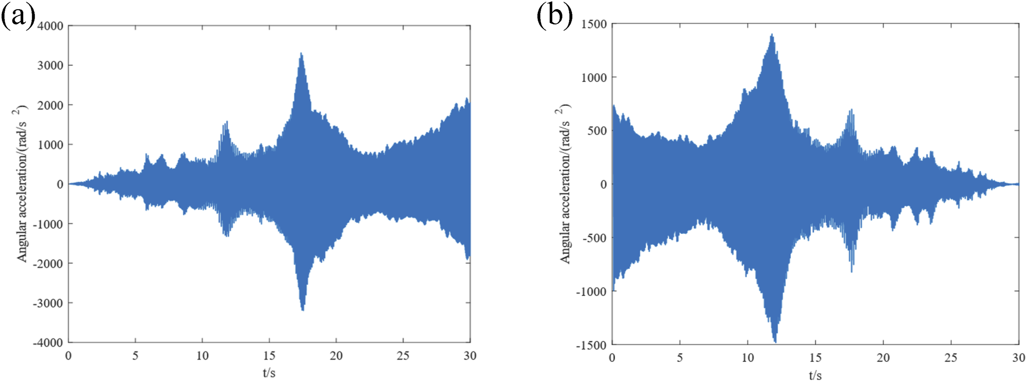
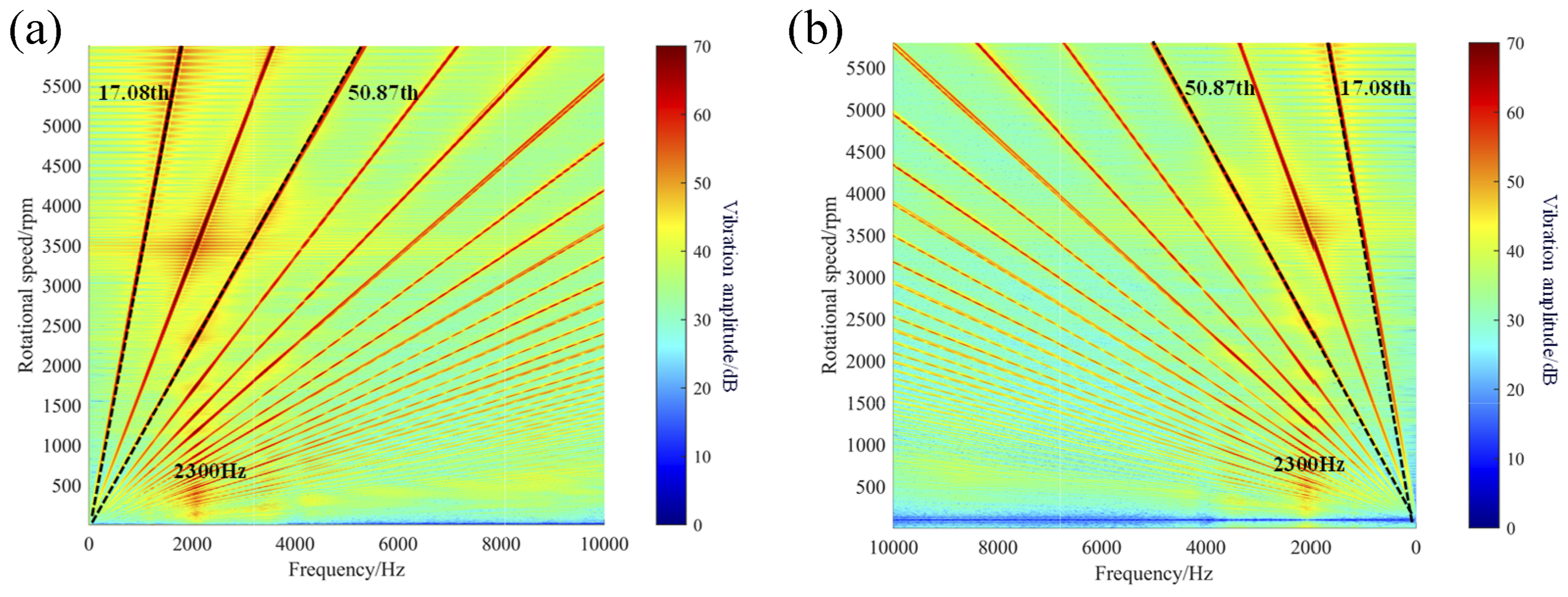
From Figure 5, it is evident that the resonance region during acceleration is primarily concentrated in the vicinity of the 11 s–13 s and 16–18 s, where significant fluctuations in the angular acceleration of the second stage planetary carrier occur. During deceleration, the driving torque of the motor is lower compared to that during acceleration, resulting in an overall noise level in the deceleration condition that is lower than in the acceleration condition. Figure 6 indicates that the frequency components associated with the mesh orders of system appear notably darker in the rotational frequency plot, highlighting their substantial contribution to system noise. The noise in the system is primarily generated by the excitation from the meshing of the planetary gears. Both the time-domain and waterfall plots reveal that resonance is particularly pronounced around 2300 Hz, with significant resonance occurring at the intersection points of the diagonal lines of various orders, leading to heightened fluctuations in angular acceleration.
If all displacement degrees of freedom in the x, y, and z directions of the dynamic system are constrained, whereas only rotational degrees of freedom are preserved, the system of 61 DOF can be further simplified to the torsional vibration model with 16 DOF. Simulation results for transient responses are obtained by the reduced model and compared with those by the 61 DOF model. In Figure 7, plotted simulation results obtained by the reduced model and resonant phenomena of the system are hardly recognized. This also highlights effectiveness of the precise dynamic model for the two-stage planetary gear system. Simulation results of the simplified torsional vibration: (a) transient responses for acceleration and (b) numerical waterfall plots of dynamic responses.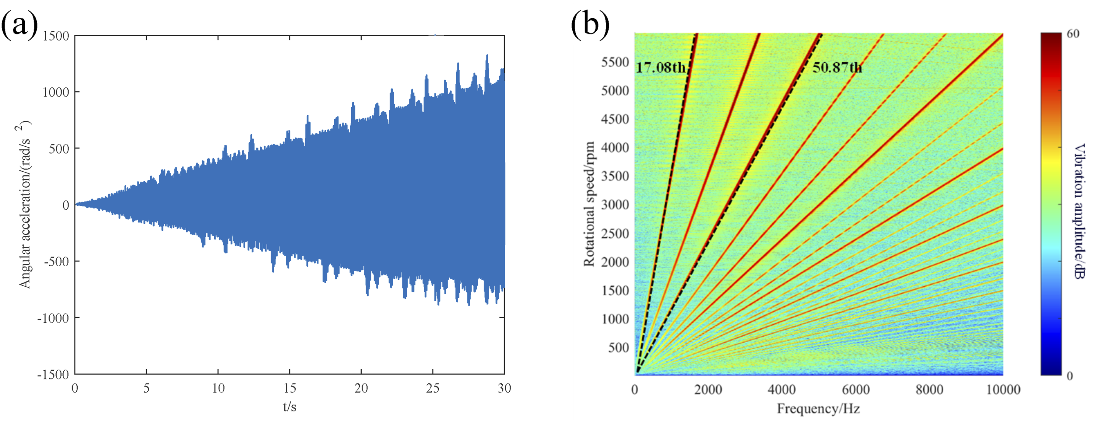
By the comparison, it is confirmed the 61 DOF model effectively to predict the resonant behaviors of the system. Significant resonant occur in the system, leading to high frequency vibro-acoustic responses during loading and unloading conditions. Additionally, by comparing simulation results of the system in acceleration with those in deceleration conditions, such time-frequency characteristics vibrations of both the two are basically similar.
Numerical results for natural frequencies of IWRMDS.
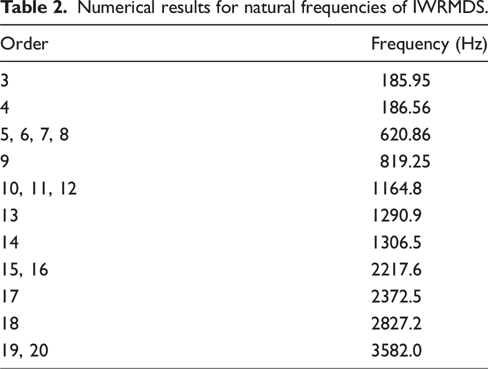
As shown in Table 2, numerical predictions for the 3rd to 20th order eigen frequencies of the IWRMDS in torsional vibrations are presented. The frequencies of the first two orders correspond to rigid body displacements in x, y, z, and angular displacement, respectively, and these are not discussed here. The vibration mode shapes corresponding to the single rooted eigen frequencies, of the 3rd, 4th, 9th, 13th, 14th, 17th, and 18th orders are taken into account. The 3rd order frequency, 185.95 Hz, represents the translational motion of the second stage output. The 4th order frequency, 186.56 Hz, corresponds to the translational-rotational motion of the second stage output. The 9th order frequency, 819.25 Hz, signifies the rotational motion of the motor, the translational-rotational motion of the first stage and the axial motion of the second stage. The 13th order frequency, 1290.9 Hz, presents the axial motion of the first sun gear. The 14th order frequency, 1306.5 Hz, designates the overall axial motion of the system. The 17th order frequency, 2372.5 Hz, denotes the translational-rotational motion of the first planetary gears, the first carrier, the second sun gear and planetary gears. Finally, the 18th order frequency, 2827.2 Hz, corresponds to the axial motion of the hub. Then, the vibration mode shapes associated with the multiple rooted eigen frequencies are considered. The frequency of 5th, 6th, 7th, and 8th orders, 620.86 Hz, is primarily related to the axial motion of the second planetary gears. The frequency of 10th, 11th, and 12th orders, 1164.8 Hz, is associated with the axial motion of the first planetary gears. The frequency of 15th and 16th orders, 2217.6 Hz, primarily describe the translational motion of the first sun gear and the frequency of 19th and 20th orders, 3582.0 Hz, is mainly involved to the translational motion of the second sun gear.
As seen from Figure 6, numerical results obtained by the model and demonstrated. Significant bright band appears around 2300 Hz. The bright band near 2300 Hz is excited by translational-rotational motion of the first planetary gears, the first carrier, the second sun gear and planetary gears, corresponding to the 17th eigen frequency 2372.5 Hz, as shown in Figure 8. Important vibration mode to parametrically excited resonances.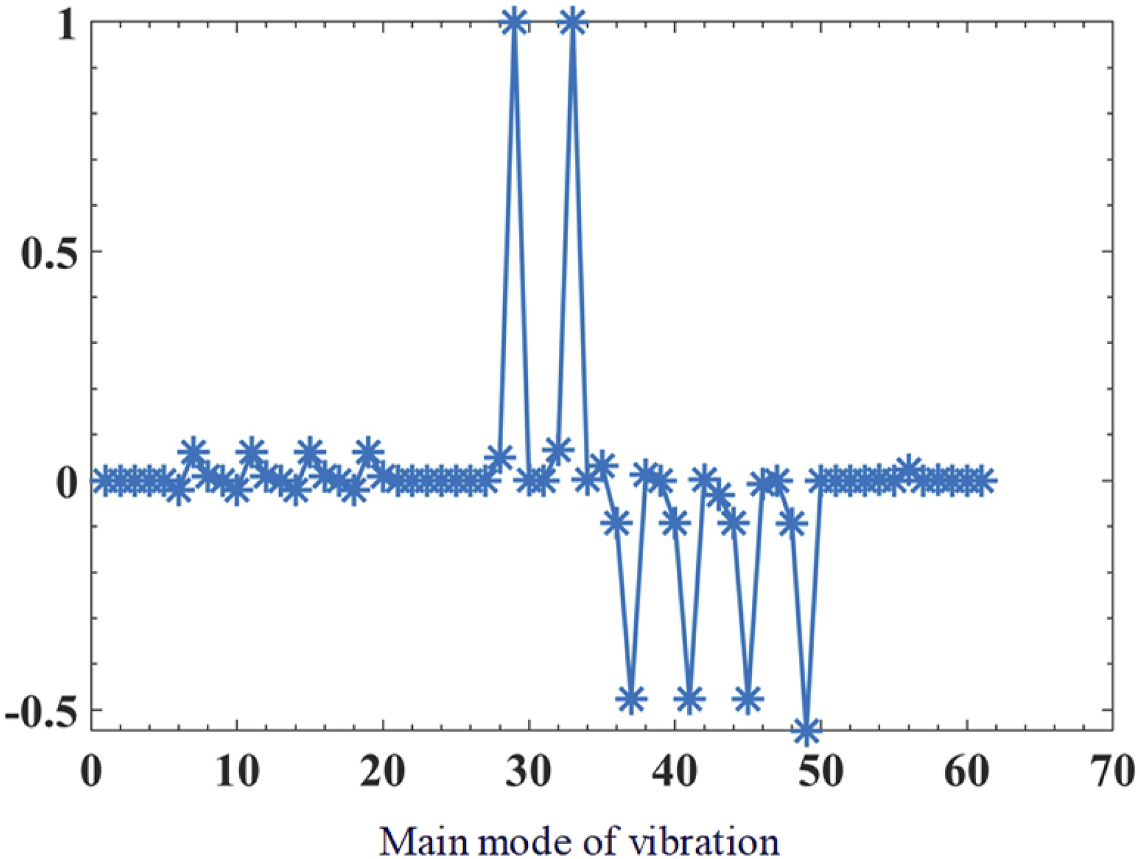
From the above analyses, it is seen that resonant vibrations are excited due to translational-rotational motion of the first planetary gears, the first carrier, the second sun gear and planetary gears. For reducing vibro-acoustic noise and improving NVH performance of the IWRMDS, design optimization of the bearing supports and components is recommended.
5. Experiment and discussion
For acquisition of test signals of the IWRMDS, such as vibration acceleration, sound pressure, torque and speed, experiments are undertaken for vibrations and vibro-acoustic features on test bench in a semi-anechoic chamber.
The IWRMDS, as shown in Figure 9, is equipped with a 16-pole, 24-slot permanent magnet synchronous motor having maximum speed of 6000 rpm, maximum torque of 230 Nm, and peak power of 85 kW at a rated 330 V. The switching frequency of the power electronics unit (PEU) for the motor control can be achieved up to the maximum 10 kHz. The IWRMDS assembly is fixed on the test bench, the output shaft is coupled to the drum of the dynamometer, and to facilitate loading and unloading. The data acquisition instruments are located in an adjacent control compartment primarily including LMS SCM205 acquisition system. Different sensors such as high-precision PCB378B02 microphones, PCB356A33 accelerometers, torque and speed sensors are provided and connected by CAN bus. The test bench and IWRMDS.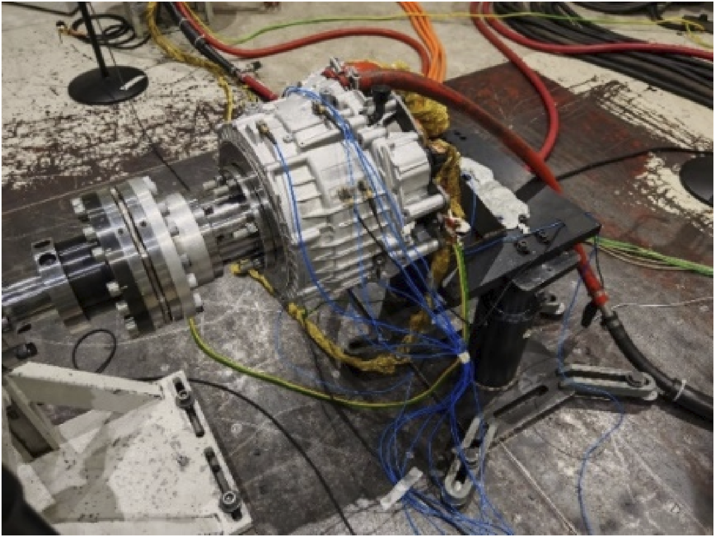
Microphones are arranged and installed around the IWRMDS in the acoustic radiation field, respectively, in front, rear, left side and right side and on top. All the microphones are one m away from the subject to be measured, as shown in Figure 10(a). Vibration accelerometers are placed, respectively, on the high-voltage box cover, the gearbox housing, and the bottom and side of the motor, as shown in Figure 11(b). The orientation of the accelerometers is defined according to global coordinate system. Real-time signals are acquired online from accelerometers, torque and speed sensors, and microphones under various operating conditions. Setup of the experiment: (a) microphones in the semi-anechoic chamber and (b) vibration accelerometers for the IWRMDS. Test results of transient responses for: (a) acceleration on the housing while the motor speed accelerators from 500 to 6000 rpm and (b) sound pressure one m away from the IWRMDS while the motor speed accelerators from 500 to 6000 rpm.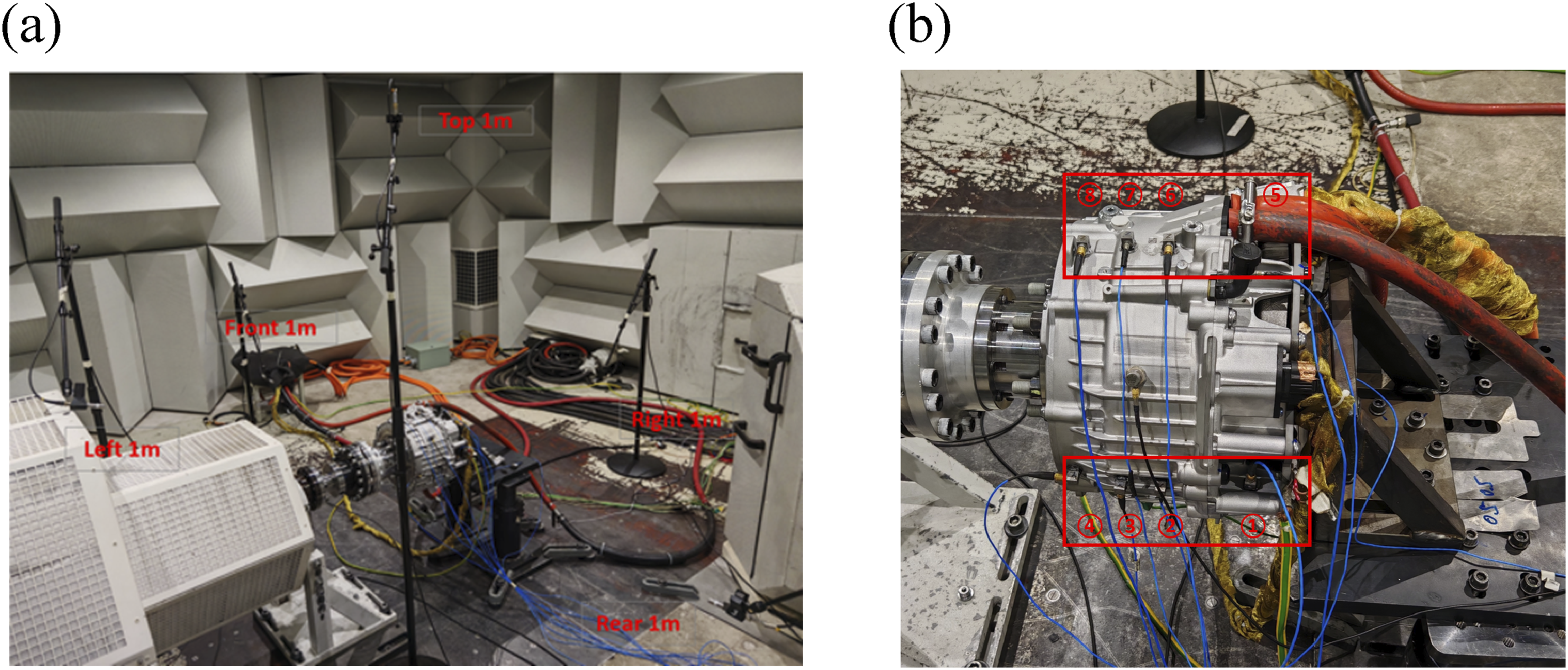
The following test conditions for the vibro-acoustic measures are required as: (1) NVH semi-anechoic chamber (2) Normal room temperature between 25°C and 30°C (3) Dynamometer
The bench tests for the IWRMDS involve two operating conditions, namely, positive acceleration with a constant torque of 200 Nm and a deceleration with a constant torque of 100 Nm. The dynamometer has a steady loading function in closed-loop speed control for specific torques.
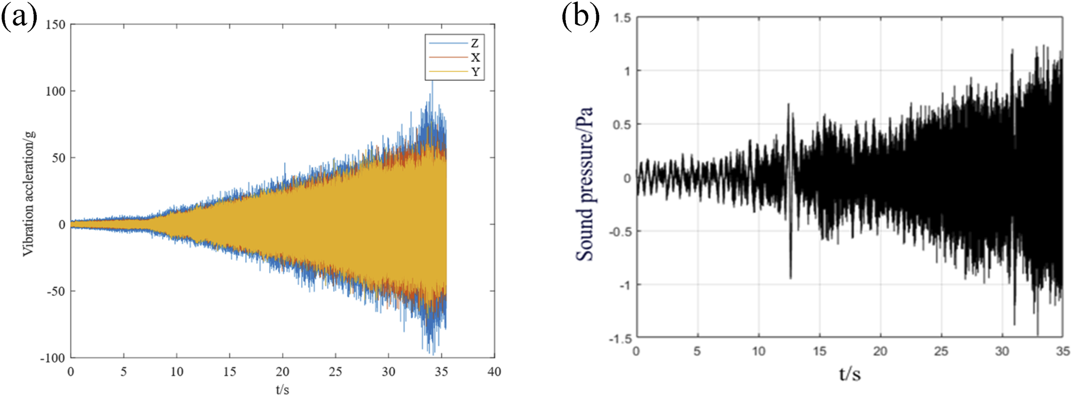
In Figure 11 are presented test results of transient responses for vibration accelerations of the housing surface and sound pressures of the IWRMDS, while the motor speed is operated from 500 to 6000 rpm under step loading torque of 200 Nm. The positive loading process takes 35 s. The motor speed gradually increases for 5.3 s in the beginning under a run-up loading torque and then the motor accelerates steadily in step loading torque for approximately 21.4 s. The motor continues to speed linearly in next 6.6 s until it reaches the maximum speed. The responses for vibration and sound pressure are plotted in Figure 11(a) and (b). It is revealed that changes in vibration acceleration can be categorized into three distinct phases. 0–7 s: vibration accelerations in the y and z coordinates are very low and negligible, and the vibration acceleration shows a slow increase. The level of sound pressure remains relatively stable. Phase 2 lasts 7–21 s: vibration accelerations exhibit a ramp-like linear increase, reaching approximately 15 g when the motor speed is around 3200 rpm. During this period, howling noise emerges intermittently and the overall sound pressure amplitude begins to rise. Phase 3 lasts 21–35 s: the vibration acceleration maintains a slow increase in a high level. The vibration acceleration in the y coordinate arrives to peaks at around 30 g, while the vibration acceleration in the z coordinate remains from 15 to 20 g until the motor speeds up to 6000 rpm. The sound pressure amplitude continues to whine noise becomes more frequent, ultimately resulting in the level of sound pressure greater than 1 Pa (approximately 94 dB). Overall, precision of the collected data sufficiently high, laying a solid foundation for further data analysis and processing, as well as optimization for improving NVH performance.
Figure 12 presents the waterfall plots for time-frequency responses of the second carrier under a torque of 200 Nm, respectively, by the numerical prediction and the experiment. As observed from the 50.87th harmonic order of the first stage planetary gear system and the 17.08th harmonic order of the second stage planetary gear system are found, respectively, by the simulation and by the experiment. Additionally, the simulation results show resonant vibration in bright band near 2300 Hz, and experimental results indicate the resonance in bright band around 2300 Hz. The contributions of different order of components excited to the system vibrations are examined and vibrations of components are evaluated. Theoretical analysis results are fairly in agreement with the experiments on the test bench. This means that the present dynamics model can be used to accurately describe transient dynamic behaviors. The dynamic model established for the IWRMDS is effective for subsequent research and development. Furthermore, in Figure 12(b), it can be observed that the motor also has a considerable impact on the system. Actually, the breathing mode, the fluctuation of the output torque and speed and the nonlinear dynamic characteristics of the motor may introduce new resonance sources to system. Waterfall plots of vibration responses for vibration in comparison between: (a) numerical predictions and (b) test results.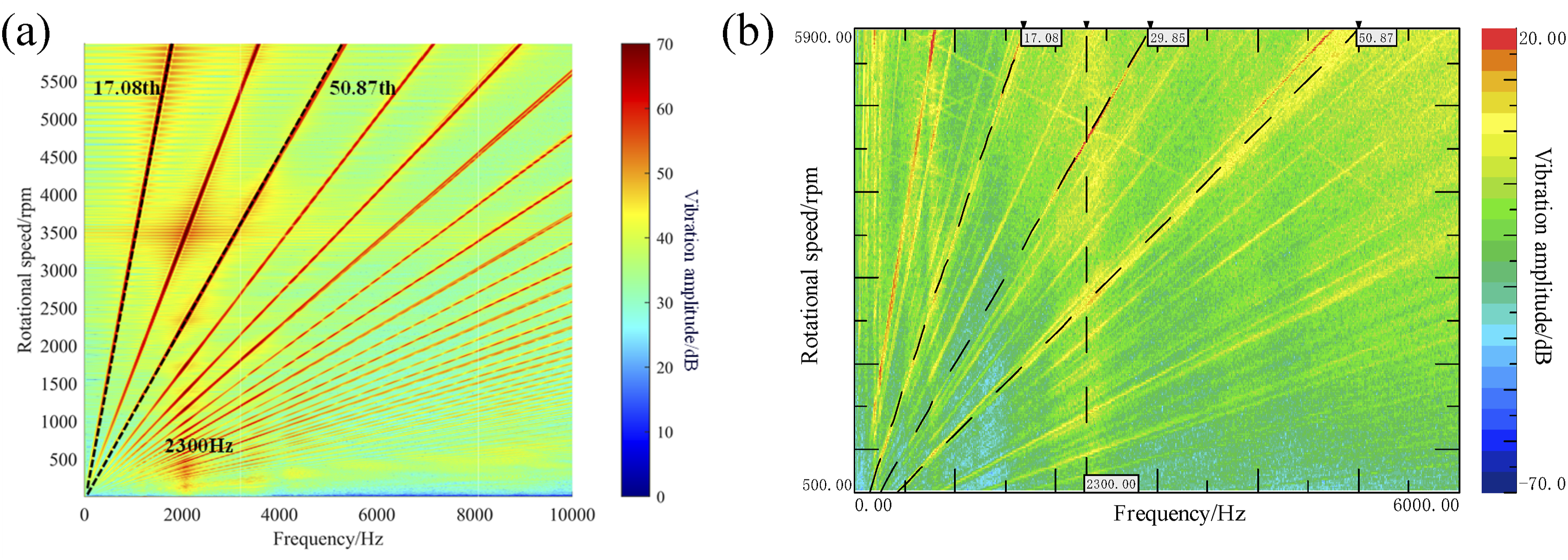
Bao et al. (2025) proposed variable stiffness materials with specific bandgap characteristics to suppress vibration propagation in a specific frequency range and change the vibration response characteristics of the system. As a crucial component of the planetary gear transmission system, the stiffness characteristics of the bearings exert a significant influence on the system’s performance. Specifically, The bearing stiffness of the first stage planetary gears Waterfall plot of dynamic responses when changing the stiffness of the bearings supporting the planetary gears: (a) when Vibration comparison of RMS when changing the stiffness of the bearings.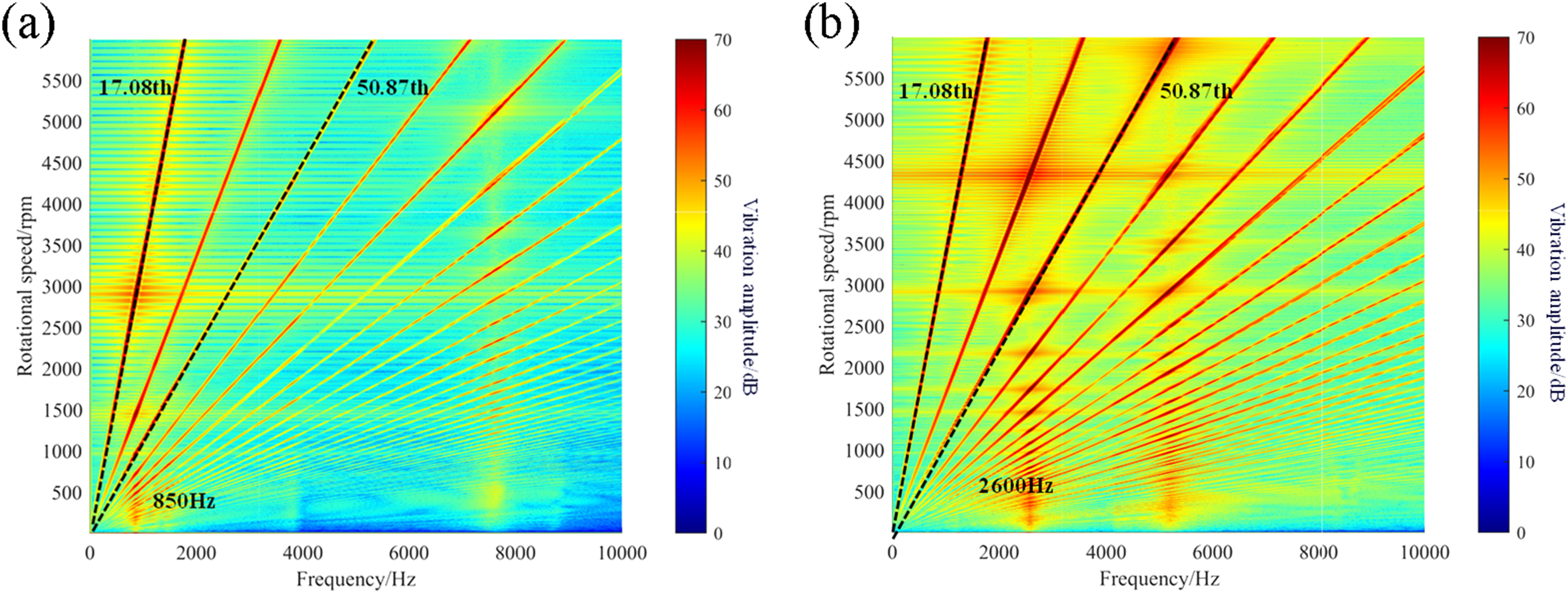
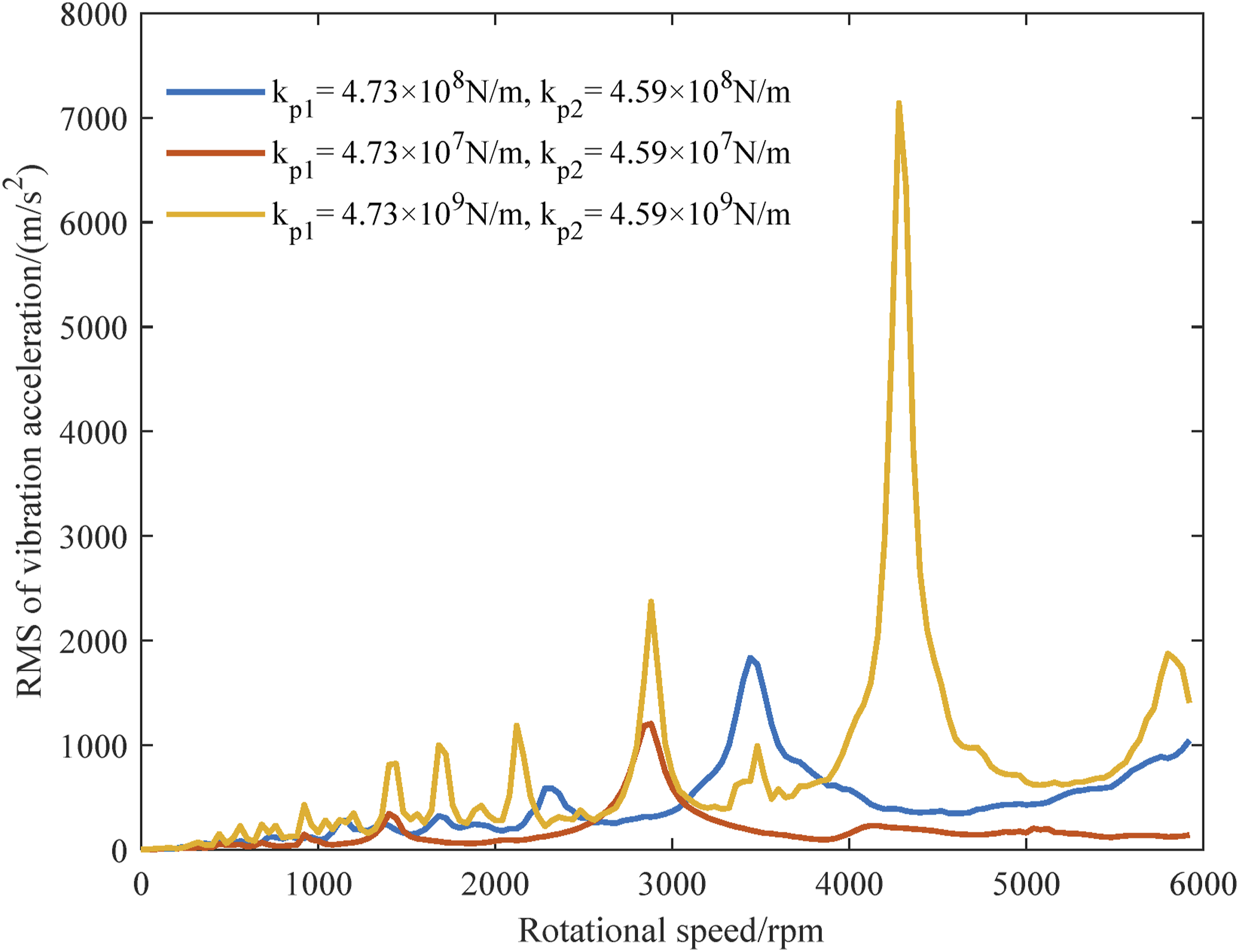
A comparison of Figures 12(a), 13(a), and (b) reveals that the initial resonance frequency is 2300 Hz. When the bearing stiffness is reduced, the resonance frequency drops to 850 Hz, whereas it increases to 2600 Hz when the stiffness is increased. As shown in Figure 14, varying the support stiffness also affects the amplitude of vibrations in the system at different rotational speeds. Consequently, selecting an appropriate bearing stiffness can effectively alter the resonance of the system, thereby enhancing its vibration and NVH performance. This finding provides significant research insights and practical guidance for optimizing the IWRMDS.
6. Conclusion
The lumped parameter dynamic model of 61 degrees of freedom is established for the compact IWRMDS and bench tests are in a semi-anechoic chamber with a dynamometer for vibrations and sound pressures. Much experimental effort is made under such typical operating conditions as the specified acceleration and deceleration, and real-time signals such as vibration acceleration, sound pressure, torque and speed. An analysis of the test data is performed and the significant bright band in the waterfall plot near 2300 Hz is found, indicating high frequency vibration and noise in the system.
The theoretical analysis is also carried out and numerical results are obtained by the dynamic model. Two prominent resonant vibrations are recognized due to the 50.87th and 17.08th orders for the first and second stage planetary gear systems. The two meshing frequencies are highly correlated with the sound pressure characteristics obtained from the bench tests. The numerical predictions for resonant vibrations near 2300 Hz are consistent with the experimental findings, thereby validating the effectiveness of the dynamic model. The vibration modal analysis is also for modal frequencies and principal vibration mode shapes. Parametrical resonances corresponding to bright bands are recognized to be primarily generated by the translational-rotational motion of the first planetary gears, the first carrier, the second sun gear and planetary gears. The vibration modal analysis shows that the system’s resonant in bright band is primarily generated by the translational-rotational motion of the first planetary gears, the first carrier, the second sun gear and planetary gears. By conducting a parametric sensitivity analysis and optimization focused on the stiffness of the transmission system, it reveals that the stiffness of the bearings supporting the planetary gears has a significant impact on modal characteristics, which can further guide the design of the system assembly and improve NVH performance.
Looking ahead, there are numerous research directions targeted at the IWRMDS. First, the interaction between the motor and the reducer may induce resonance in the system, suggesting that we can optimize both the structure of the motor and the connection between the motor and the reducer. Additionally, the stiffness, damping and nonlinear characteristics of the vehicle suspension system exert a non-negligible influence on the resonance behavior of the IWRMDS, which can be further studied and optimized. These research avenues will provide us with more comprehensive and in-depth insights, contributing to the advancement of the system.
Footnotes
Declaration of conflicting interests
The author(s) declared no potential conflicts of interest with respect to the research, authorship, and/or publication of this article.
Funding
The author(s) disclosed receipt of the following financial support for the research, authorship, and/or publication of this article: This work is supported by National Key R&D Program of China (2023YFB2504300), and Shanghai Automotive Industry Technology Development Foundation: Industry-University-Research Project (No. 2212).