
Abstract
Periodic grinding marks generated during rail grinding can readily serve as excitation for the initiation of rail corrugation. To improve the rail surface roughness after rail grinding, an improvement of the grinding carriage frame was conducted based on the analysis of resonance characteristic. Vibration tests revealed that the vibrations were dominated by the grinding motor’s rotation at the frequency of 60 Hz, and there were significant vibration responses ranging from 59 to 63 Hz in the grinding carriage frame. Modal analysis further revealed that the longitudinal expansion and contraction of the primary longitudinal beams of the grinding carriage frame with natural frequency of 57.6 Hz and the rolling motion of the crossbeams with natural frequency of 60.3 Hz were exacerbated by the motor rotation at 60 Hz. From the perspective of avoiding resonance, a structural improvement of the frame was conducted, resulting in a notable reduction in motor vibration. The vibration jump-up of the improved structure from idle condition to grinding condition decreased by 66% compared to that before structural improvement. The rail roughness at the wavelength corresponding to the resonant frequency decreased from 19.8 dB before grinding to 15.3 dB after grinding, representing a reduction of 22.6%, and this enhanced grinding effect was 1.9 times that of the original structure. Therefore, the improved grinding carriage frame can significantly alleviate the impact of resonance, thereby reducing the fluctuations in grinding force during the process, and substantially enhancing the quality of rail grinding.
1. Introduction
As railway operating speeds, volumes, and traffic densities continue to escalate, dynamic loads between wheel and rail have significantly intensified, leading to increasingly severe damage phenomena such as corrugation, fatigue cracks, rail squashing, rail peeling, rail squat, and side wear of rails (Bedoya-Zapata et al., 2021; Chen et al., 2023a, 2023b; Grassie, 2009). These damages pose a grave threat to railway operational safety and ride comfort (Ling et al., 2014). So, researchers have proposed numerous measures to control rail damage, including the use of rails with higher hardness (Kanaev et al., 2023), track vibration reduction (Zhang et al., 2023), wheel-rail lubrication (Robles et al., 2023), and rail grinding (Kuffa et al., 2016; Zhou et al., 2019). Among these, traditional rail grinding stands as the most commonly employed and effective maintenance practice among railway authorities worldwide (Jin et al., 2010).
Traditional rail grinding, also referred to as active grinding, involves the utilization of an electric motor to power a grinding stone to rotate at high speeds while maintaining a stable contact with the rail surface through the action of hydraulic mechanisms, thereby achieving the removal of superficial rail materials. Nevertheless, despite its efficacy in addressing rail defects and issues under this grinding mechanism, it may also pose new challenges and problems for the rail surface condition, such as rail surface burning and the creation of initial irregularities.
First, the contact area between the grinding stone and rail reaches exceptionally high temperatures, ranging from 200°C to 500°C. Such extreme temperatures can easily burn the rail or even generate martensitic white layers (Zhou et al., 2021), leading to “pre-fatigue” in the rail (Steenbergen, 2016). Researchers have conducted extensive theoretical and experimental studies focusing on the relationship between grinding parameters (Lin et al., 2018; Uhlmann et al., 2016; Zhou et al., 2019), grinding stone properties (Wang et al., 2018, 2020), and grinding quality aspects like thermal damage and surface roughness (Mesaritis et al., 2020; Xu et al., 2018). These studies combine experimentation and theory to investigate the influence of grinding parameters, including grinding pressure, motor speed, and working speed, on grinding quality, optimizing these parameters accordingly. Furthermore, by exploring the effects of grinding stone characteristics like size, abrasive composition, grit hardness, and porosity on grinding efficiency, quality, and stone lifespan, improved grinding stones have been developed (Wu et al., 2019).
Second, the periodic motion of the grinding stone under motor drive inevitably leaves periodic residual marks on the ground rail surface. Chen and Ishida (2006) found that these marks, regardless of initial roughness, converge to a similar roughness level after equivalent wheel-rail rolling cycles, with surface marks nearly disappearing. Thus, residual marks from grinding have minimal impact on subsequent rail fatigue cracks. However, reports (Du et al., 2021) indicate that when the dynamic frequency induced by these marks aligns with the track’s sensitive frequency, it can excite wheel-rail system resonance, acting as a source for new corrugation. As evidenced by the tracking tests conducted on rail corrugation (Figure 1) of a high-speed railway in China, it was observed that the pre-ground rails developed severe corrugation within just one month of operation. The wavelength of this corrugation, approximately 60 mm, coincides with the wavelength range (56–64 mm) of the periodic grinding marks left behind by the grinding process. In contrast, the rails that had not undergone pre-grinding treatment remained free from corrugation, suggesting a direct correlation between the pre-grinding procedure and the subsequent emergence of rail corrugation. Rail corrugation caused by rail grinding on a high-speed railway in China.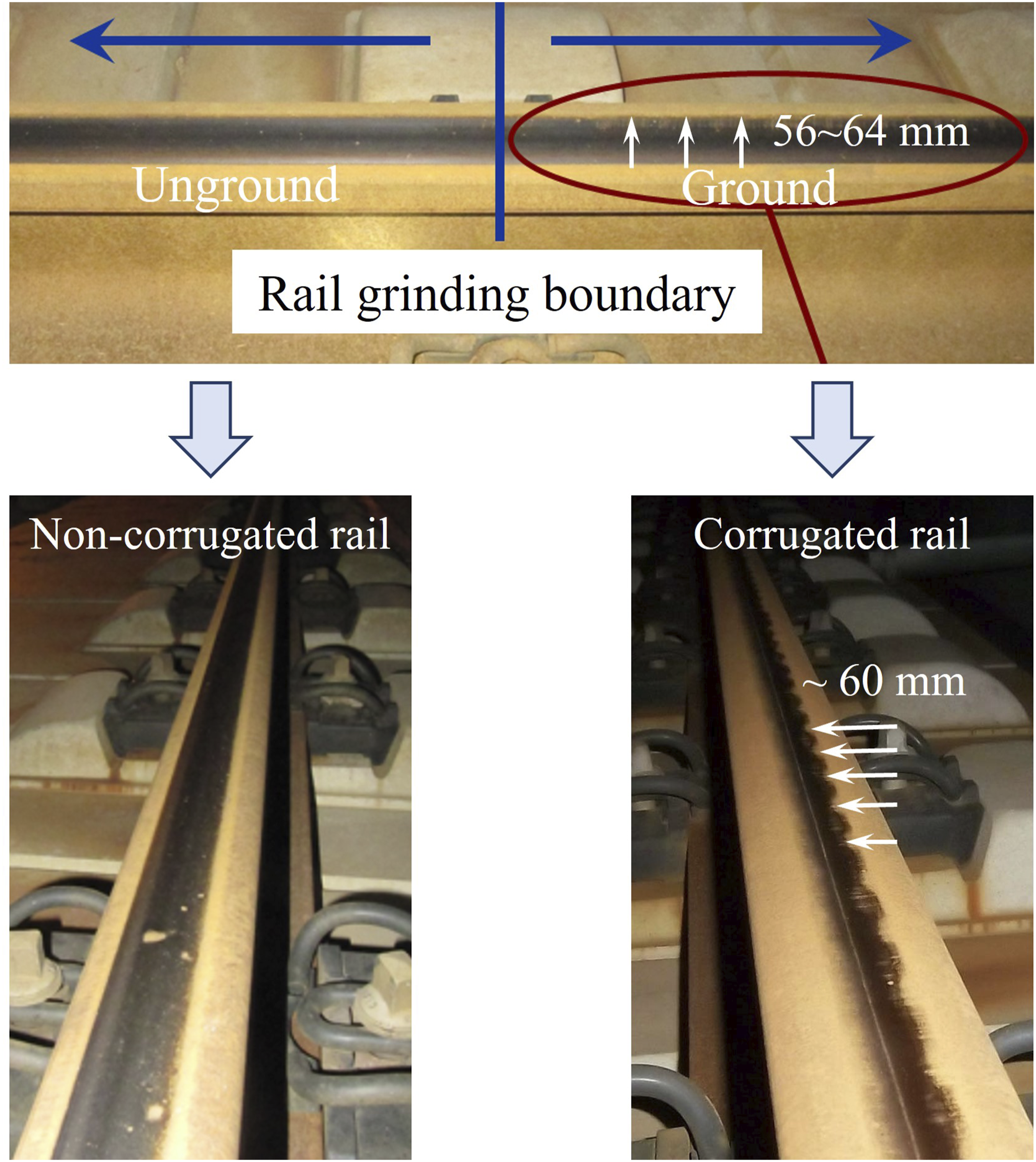
To mitigate rail corrugation arising from residual marks, Tanaka and Miwa (2019) established a numerical model for corrugation assessment through field tracking, determining the residual roughness limit post-grinding. Cui et al. (2023) determined the grinding limit for corrugated rails by analyzing safety indices related to dynamic characteristics in metro systems, coupled with wheel-rail friction-induced vibration characteristics. Serge et al. (2014) proposed a new grinding strategy (higher grinding speed), which shifted the wavelength of the residual periodic irregularities from 40 mm to 100–150 mm and reduced the tonal peaks in the roughness spectrum. Kuffa et al. (2016) presented a new newly developed rail grinding strategy that combines both roughing and finishing techniques, which improves the roughness of the rail surface. Croft et al. (2023) analyzed the influence patterns of different grinding equipment including conventional rail grinding, rail milling, and from newer specialist acoustic grinding technologies on rail roughness.
Existing research on residual grinding marks primarily focuses on the determination of their limiting values and optimizing of grinding strategies. However, given that this type of grinding inevitably results in periodic scratching phenomena, enhancing the roughness level of residual periodic grinding marks post-grinding is of paramount importance. Nevertheless, relatively few studies have been conducted in this specific area. Zeng et al. (2023) embarked on an investigation focusing on the grinding hydraulic system, revealing subpar performance in the removal of corrugation from steel rails during constant-power grinding operations. Consequently, they improved the hydraulic power, and simulation results demonstrated a significant improvement of 12.7% in corrugation removal efficiency following the improvement. However, this method poses exceptionally high demands on real-time corrugation detection and analysis, as well as precise control of the hydraulic system. Consequently, it is challenging to enhance grinding quality solely through power adjustments in practical scenarios. Moreover, deviations in the detection of corrugation peaks and troughs positions, coupled with hydraulic control inaccuracies, may exacerbate the corrugation problem. In fact, in the field of building structures, controlling vibration through structural improvements has achieved good results, such as controlling the vibration of super high-rise buildings by improving the viscous damping outrigger system (Lu et al., 2018) and mitigating the vibration of the precision platform by optimizing the parameters of the vibration isolation and mitigation system (Xu et al., 2019). Therefore, improving the roughness level of residual grinding marks through structural modifications represents a promising approach to enhancing grinding quality. Nevertheless, due to the intricate structure and extensive impact range of grinding equipment, there is currently a lack of relevant reports on structural improvement in this regard.
This paper focuses on enhancing the reduction of residual initial roughness amplitude resulting from the grinding process by conducting a comprehensive vibration test on the critical components of rail grinding equipment, thereby obtaining their specific vibration characteristics. Through hammer impact testing, the natural frequencies of these critical components were identified, allowing us to pinpoint the modes and mode shapes that are proximate to the motor’s rotational frequency. Subsequently, finite element modal analysis was employed to improve the structural design, ensuring that the inherent frequencies of the structure are shifted away from potential resonance frequencies, thereby mitigating vibrations induced by the motor’s rotation and improve the overall grinding quality. Finally, the effectiveness of these improvements was validated through field tests.
2. Key component vibration characteristics
2.1. Rail grinder
The rail grinding carriage, as illustrated in Figure 2, constitutes a pivotal component of the grinding train and serves as a crucial structure for carrying out rail grinding operations. Comprising rail grinder wheel, frame, bracket, rail grinder lifting cylinder, hoisting pneumatic cylinder of grinding motor, angle adjustment cylinder of bracket and other integral parts, it works in unison to achieve the surface grinding of railway tracks. Rail grinding carriage: ① wheel; ② frame; ③ bracket; ④ grinding motor; ⑤ grinding stone; ⑥ rail grinder lifting cylinder; ⑦ hoisting pneumatic cylinder of grinding motor; and ⑧ angle adjustment cylinder of bracket.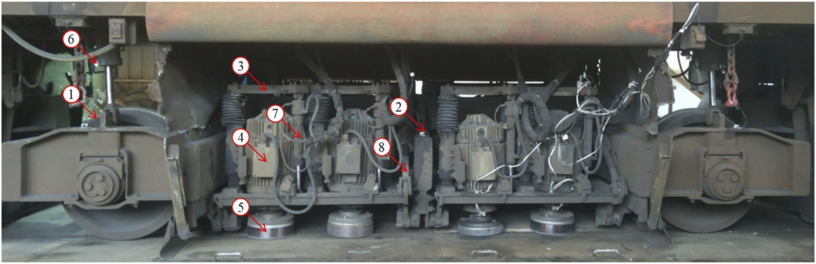
Each rail grinder is equipped with four brackets, positioned symmetrically on both sides of the frame. Within each bracket, two grinding motors are installed, each motor equipped with a grinding stone mounted beneath its rotating shaft. This configuration constitutes a single grinding unit. Consequently, a single rail grinder is furnished with a total of four grinding units.
When the rail grinding train arrives at the designated position, the rail grinder descends onto the rail surface through the rail grinder lifting cylinder. With the action of the hoisting pneumatic cylinder of grinding motor, the grinding stone makes contact with the steel rail surface at a pre-set pressure, while the hydraulic cylinder also ensures the stability of the contact pressure. Furthermore, the grinding angle can be adjusted by the angle adjustment cylinder of bracket, enabling grinding at varying lateral positions on the rail surface. The grinding motors operate at a rated speed of 3600 r/min.
2.2. Vibration characteristics
In the field of structural vibration research, vibration testing and analysis is a commonly used and effective method (Lu et al., 2010; Xu et al., 2023). In this study, to comprehend the structural vibration characteristics of the rail grinding carriage, a comprehensive vibration acceleration testing was conducted on the critical component (grinding motor) utilizing the DHDAS dynamic testing equipment in conjunction with high-temperature-resistant piezoelectric sensors (with a sensitivity of 50 mV/g and a measurement range of 100 g). This test was carried out throughout the entire grinding process. During the testing period, the sampling frequency was set at 5 kHz to ensure accurate data capture.
Three distinct rail grinder states were defined as follows:
2.3.1. Static state
The rail grinding train is stationary, and all grinding motors are switched off.
2.3.2. Motor idling
With the rail grinding train stationary, the grinding motors are activated and its speed gradually increased to reach the rated speed 3600 r/min. However, the hoisting pneumatic cylinder of grinding motor remained inactive, and consequently, there was no contact between the grinding stone and the rail.
2.3.3. Grinding operation
The rail grinding train moves forward at a set speed, while the grinding motors rotate at a high speed at its rated rpm. Under the action of hoisting pneumatic cylinder of grinding motor, the grinding stone comes into contact with the rail and maintains a certain pressure, thereby cutting the surface material of the rail.
Figure 3(a) presents the frequency and time-frequency characteristics of the vertical vibration acceleration of the motor during the grinding operation at a speed of 16 km/h. It can be seen that the vibrations are primarily dominated by 60 Hz and its harmonics, persisting throughout the entire grinding process. Vibration characteristics of grinding motor: (a) Frequency and time-frequency characteristics of the vertical vibration acceleration of the motor during the grinding operation and (b) vibration amplitudes at 60 Hz from the grinding motor under various operating conditions.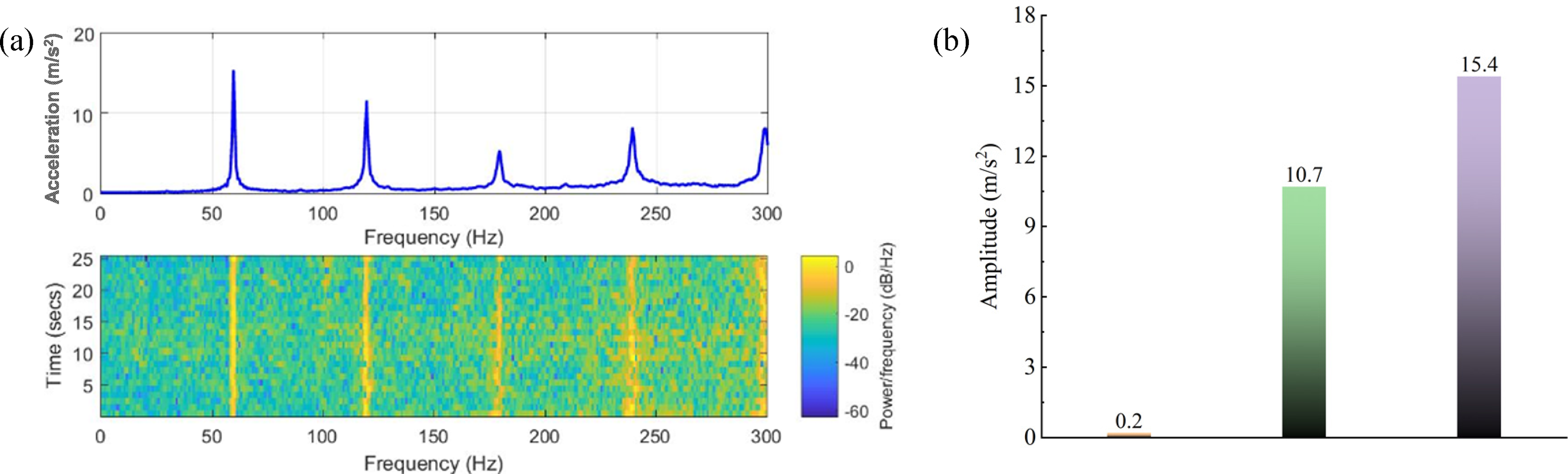
The vibration amplitudes at 60 Hz from the grinding motor under various operating conditions were extracted, as shown in Figure 3(b). In the static state, the motor vibration is negligible, virtually zero. However, upon motor activation, the vibration amplitude surges instantaneously to 10.7 m/s2. When the grinding stone comes into contact with the rail, this vibration intensifies further, exhibiting a 43.9% increase compared to when the motor is idling. This amplification of periodic vibrations may induce a 60 Hz cyclic fluctuation in both the grinding stone and the resulting grinding force during the grinding process, ultimately compromising the quality of the rail grinding. This is also the primary reason for the residual periodic irregularities on the surface of the rail after grinding.
Considering that the rail grinding carriage frame serves as the pivotal component for bearing and transmitting the motor’s vibrations, ensuring that its natural frequency does not overlap with the motor’s rotational frequency is an improvement choice for mitigating the dominant frequency vibrations in the rail grinder.
The vibration transmission characteristics of the grinding carriage frame were clearly identified through impacts delivered by the force hammer tests, as shown in Figure 4(a). The frequency response function (FRF) of the system, being a vital frequency domain characteristic parameter, can be derived from the relationship that exists between the input excitation and the corresponding output response at specific frequencies. This FRF can subsequently be employed to identify modal parameters of the system. The vibration transmission characteristics of the rail grinding carriage frame: (a) on-sit force hammer tests and (b) the frequency response function of the system.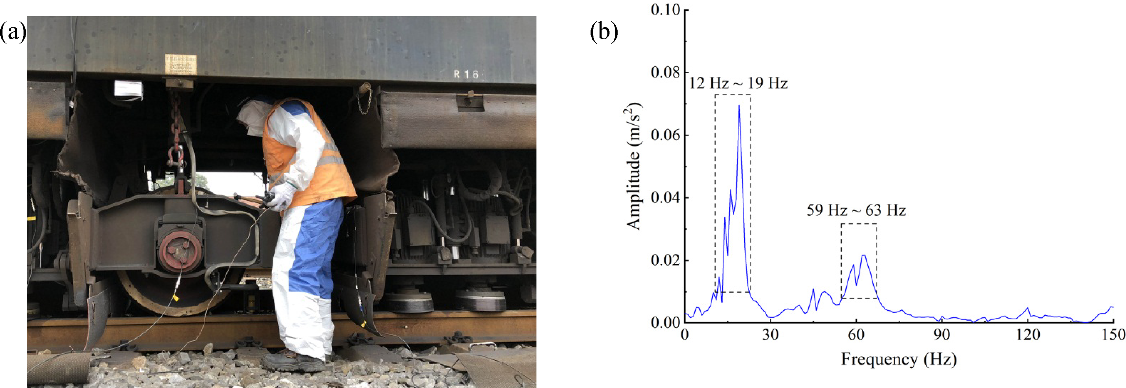
High-precision, high-performance vibration testing equipment from the renowned Danish company Brüel & Kjær was utilized in the conducted tests. This comprehensive setup encompassed a force hammer, acceleration sensors, data cables, a signal acquisition module, and a signal analysis system. Specifically, the force hammer employed was the Type 8207 heavy hammer, capable of delivering an excitation force ranging from 0 to 35584 N. The accelerometers used were 4321 model piezoelectric triaxial charge-type accelerometers, with a measurable frequency range of 0.1 to 10000 Hz and a sensitivity of 1.0 mV/ms2. The signal acquisition module was a LAN-XI 3053 model, a high-density 12-channel input module capable of measuring frequencies up to 25.6 kHz.
During the test, the excitation source on the rail grinder was struck with a force hammer, while the force sensor mounted on the hammer captured the excitation force signals. Accelerometers installed at various measurement points on the rail grinder acquired the response signals, which were amplified by a charge amplifier before being input into the signal acquisition module. The data from each channel in the signal acquisition module was ultimately transmitted to a signal analysis system on the computer for processing and analysis. In this test, the excitation source was located at the wheel-rail contact position, with the excitation direction perpendicular to the wheel tread, and the response position was set at the center of the frame.
Figure 4(b) shows the FRF results from the center of grinding carriage frame. It can be observed that there are significant characteristic frequencies ranging from 12 to 19 Hz and 59 to 63 Hz within the grinding carriage frame. Notably, the characteristic frequency of 59 to 63 Hz is close to the rotational frequency of the grinding motor, which is highly prone to causing resonance. This resonance can subsequently intensify the vibration of the grinding stones, ultimately degrading the grinding quality.
3. Structural improvement and effect analysis
3.1. Finite element analysis of grinding carriage frame
A finite element model of the rail grinding carriage frame was established using ANSYS software, as shown in Figure 5(a). The frame material is steel, with a density of 7850 kg/m3, an elastic modulus of 200 GPa, and a Poisson’s ratio of 0.29. Due to the large and complex structure of the structure, a four-node tetrahedral mesh element was adopted for meshing. To balance computational efficiency and accuracy, a local refinement was performed on the central part of the frame, with a minimum mesh size of 1 mm. The model comprises a total of 442,607 nodes and 1,579,943 elements. Structure improvement of grinding carriage frame: (a) finite element model of original structure and (b) improved structure with blue as reinforcement.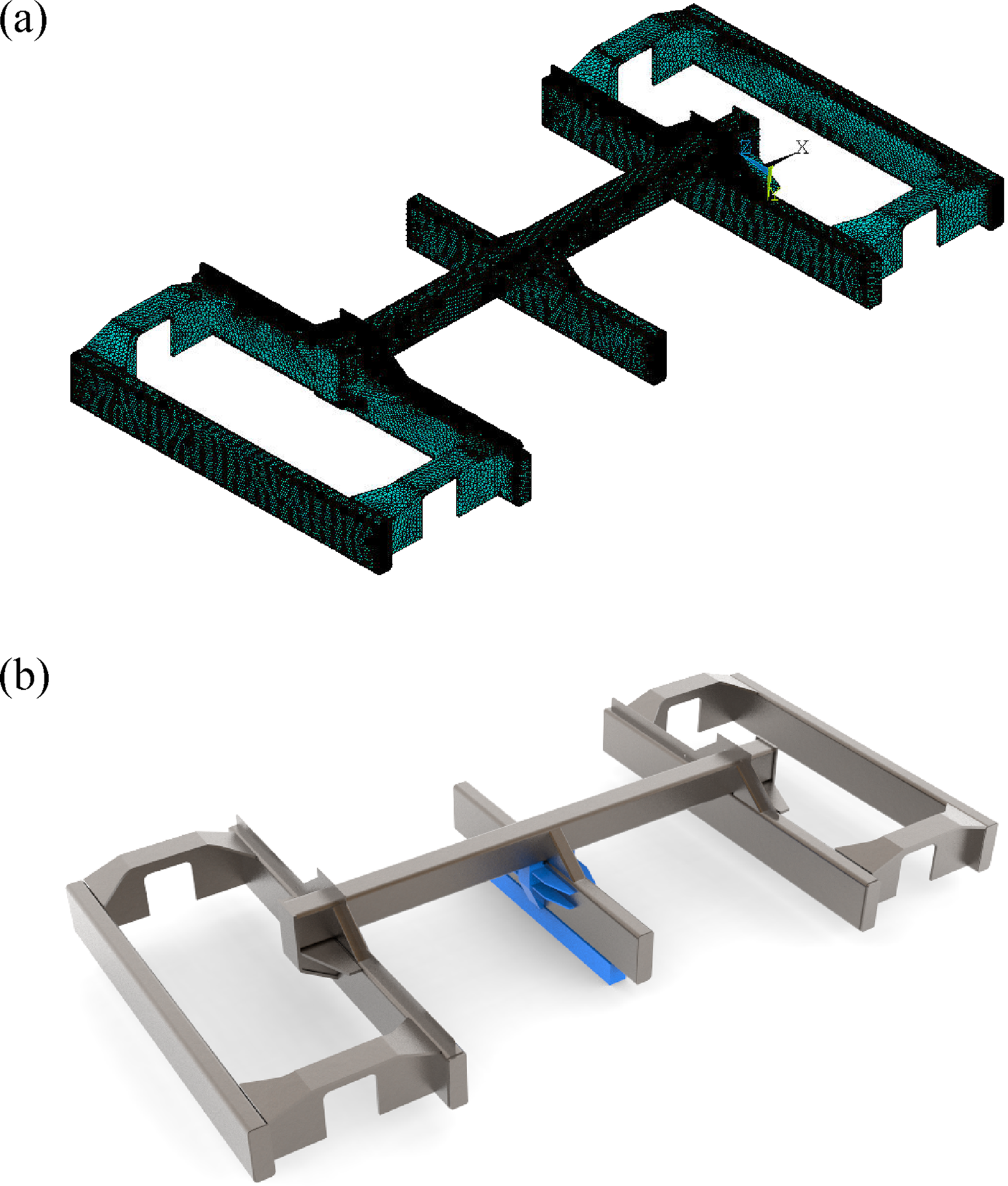
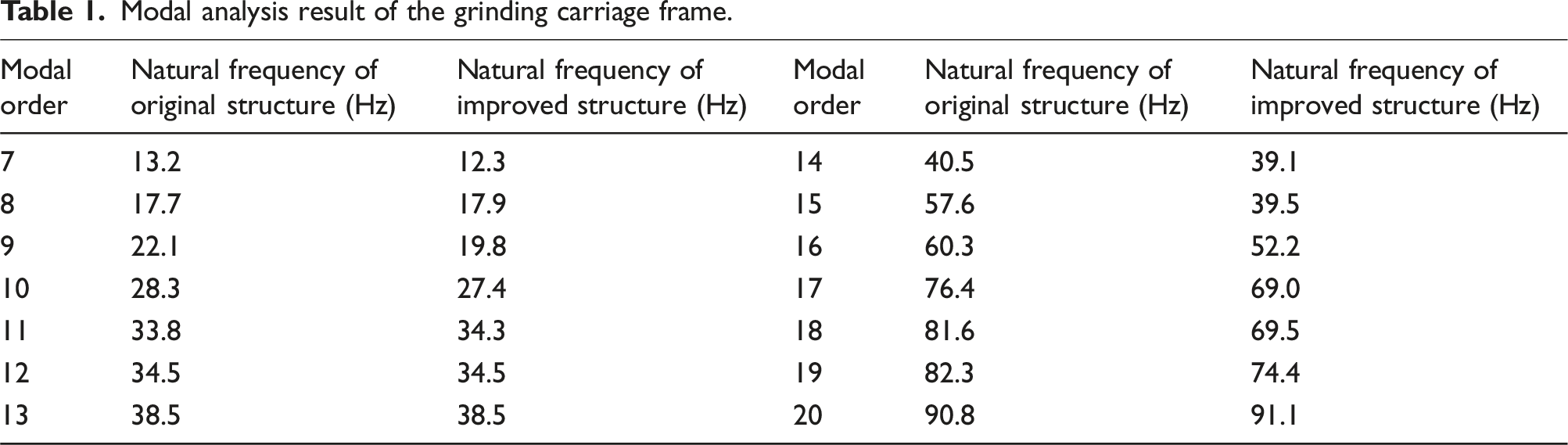
Modal analysis result of the grinding carriage frame.
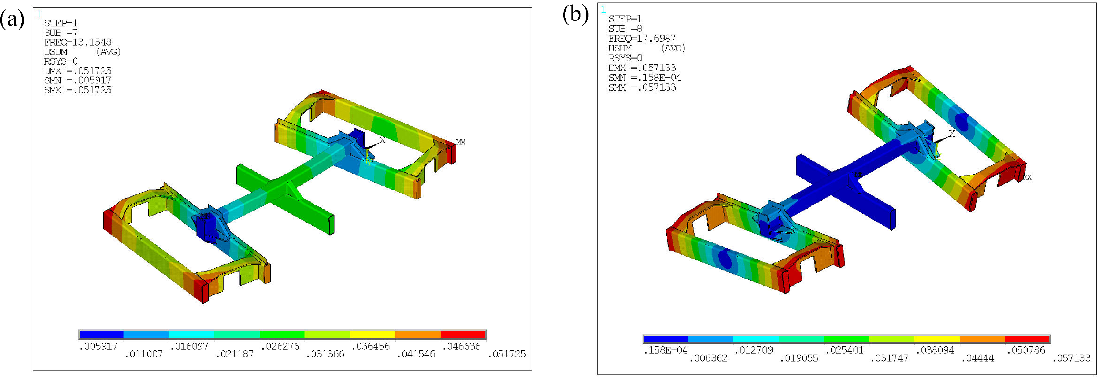
Modal vibration shapes at different order of original: (a) 7th modal mode and (b) 8th modal mode.
Furthermore, the natural frequency of the 15th modal mode is 57.6 Hz, as shown in Figure 7(a) and its vibration mode is characterized by the longitudinal expansion and contraction of the primary longitudinal beams of the grinding carriage frame. The natural frequency of the 16th modal mode is 60.3 Hz, as shown in Figure 7(b) and its vibration mode is characterized by the rolling motion of the crossbeams. These frequencies coincide with the secondary peak range of 59 ∼ 63 Hz indicated in the frequency response function, underscoring the validity of the finite element model and modal analysis. Modal vibration shapes at different order of original: (a) 15th modal mode and (b) 16th modal mode.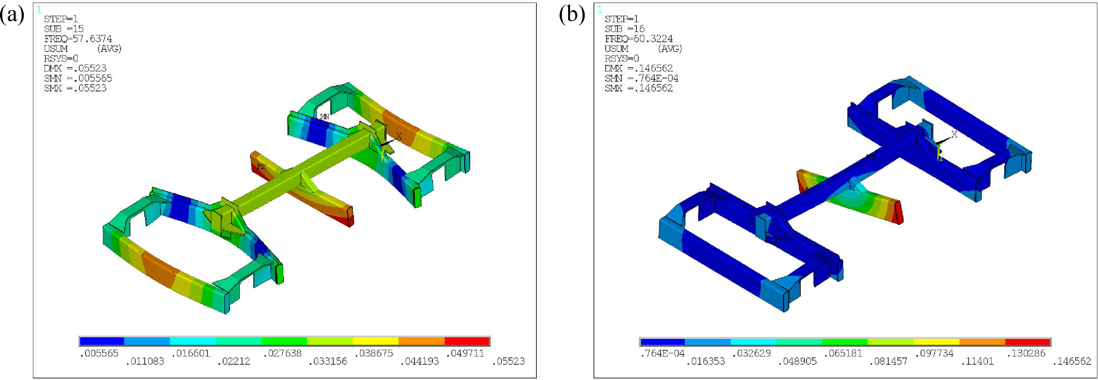
Crucially, the proximity of the 15th and 16th modal frequencies to the motor excitation frequency of 60 Hz heightens the risk of resonance, which could amplify motor vibrations and deteriorate grinding quality.
Properly adjusting the longitudinal expansion motion of the primary longitudinal beams and rolling motion of the crossbeams to avoid the sensitive frequency band (59∼63 Hz) as much as possible is an effective measure to improve grinding quality. To achieve this, reinforcing structures were added to the connections between the central crossbeams and the longitudinal primary beams of the grinding carriage frame, and the mass of the crossbeams was increased, as indicated by the blue portion in Figure 5(b). The free modal analysis and frequencies of the improved grinding carriage frame are presented in Table 1, revealing that there are no modes near the sensitive frequency of 60 Hz within the first 20 modes. Specifically, the vibration frequency of the longitudinal expansion and contraction of the primary longitudinal beams decreased to 52.2 Hz from 57.6 Hz, as depicted in Figure 8(a). The vibration frequency of the rolling motion of the crossbeams decreased to 39.5 Hz from 60.3 Hz, as depicted in Figure 8(b). It is noteworthy that the modal order corresponding to the vibration mode will undergo certain variations due to the changes of the structure. Therefore, from a modal analysis perspective, these improvement measures can effectively alleviate the initial irregularity level arising from the periodic variation of grinding force caused by the self-rotation of the grinding motor. Modal vibration shapes at different order of improved structures: (a) 16th modal mode and (b) 15th modal mod.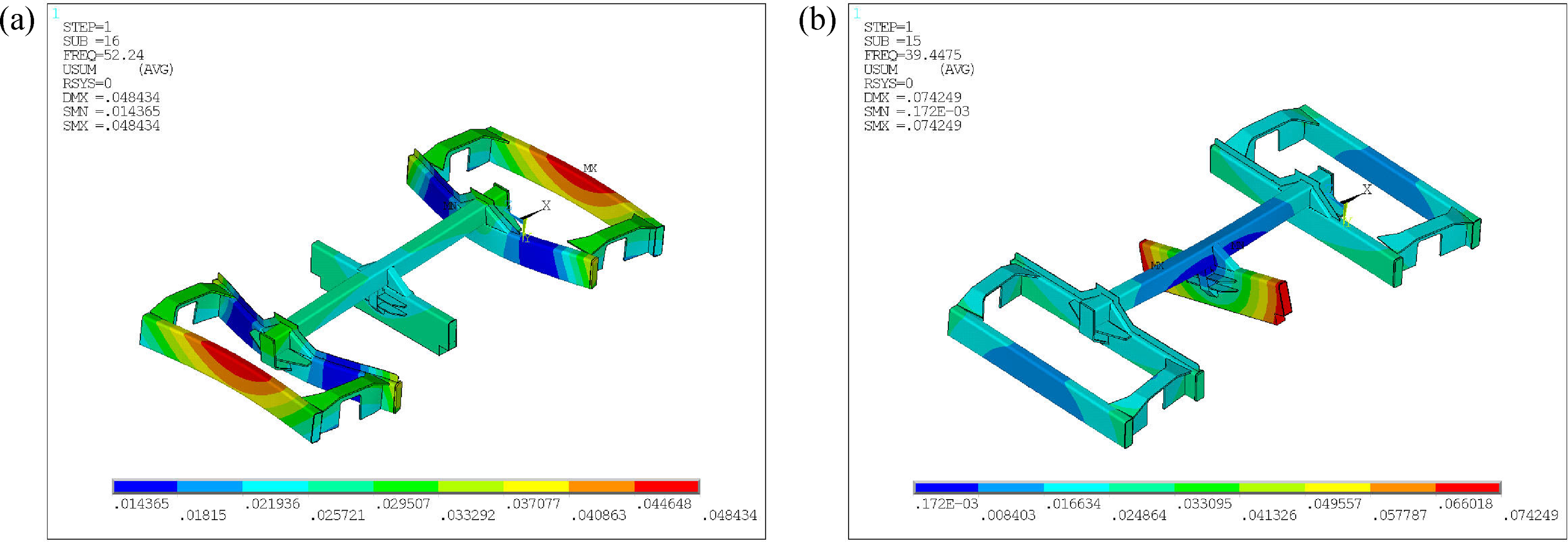
3.2. Effect analysis of improvement
This model of grinding train comprises a total of five cars, with the third car serving as the power car, and cars numbered 1, 2, 4, and 5 functioning as grinding cars. Each grinding car is equipped with three rail grinding carriages. An actual vehicle modification was conducted on the frame of the first grinding carriage in car 2, while the third grinding carriage in car 4 served as the control group. Field grinding was conducted on a test track, which was a 500-m straight ballasted track. The rails used are 60 kg/m U71Mn, featuring a CN60 rail head profile. The sleepers used are concrete sleepers, with a spacing of 0.6 m between them. The results of the rail surface roughness test are shown in Figure 10, revealing an initial irregularity with a wavelength of 80 mm. The grinding parameters were set according to routine grinding practices, with a grinding operation speed of 16 km/h and a grinding stone angle of 0 degrees. Throughout the process, the motor’s vibration characteristics under both idling and operational grinding conditions were recorded, along with the pre- and post-grinding surface roughness of the rail.
As depicted in Figure 9, the vibration of the grinding motors in both the original and the improved rail grinder are presented at the primary frequency of 60 Hz during motor idling and grinding operation. Under idle motor conditions, the vibration at the grinding motor of original rail grinder measures approximately 1.4 m/s2, while the vibration at the motor of the improved rail grinder is 2.1 m/s2, representing a nearly 50% difference between the two. This disparity primarily stems from inherent variations in the vibration characteristics of the two rail grinders themselves. Consequently, it is unscientific to solely evaluate the improvement based on the amplitude of motor vibration. Comparison of vibration jump-up between original and improved structures at the primary frequency of 60 Hz during motor idling and grinding operation.
Therefore, the vibration jump-up, which specifically refers to the increase in vibration amplitude at the primary frequency of 60 Hz for the motor during grinding operations, when compared to its state of idleness, has been introduced to quantify the improvement effect. The grinding motor vibration jump-up of the original rail grinder, when operating under grinding conditions, experienced a significant increase of 425% compared to its idle state. In contrast, the vibration jump-up of the improved rail grinder rose by a mere 141%. The vibration jump-up of the improved structure from idle condition to grinding condition decreased by 66% compared to that before structural improvement. This marked decrease indicates that the vibration energy of the enhanced grinding motor in the vicinity of 60 Hz has been substantially weakened, which is advantageous for improve the grinding quality.
Figure 10(a) and (b) present the rail roughness levels before and after grinding for the original rail grinder. It can be observed that there exists an initial corrugation phenomenon with a wavelength of 80 mm on this track. The data from the middle 2-m segment is selected and subjected to a band-pass filtering process between 30 and 100 mm. As shown in Figure 10(a) regarding the spatial characteristics of corrugation, there is little change in the geometric features and amplitudes of the rail corrugation before and after grinding. The one-third octave band analysis (Figure 10(b)) reveals that after rail grinding, the roughness level at the characteristic wavelength decreases from 15.8 dB to 13.9 dB, a reduction of approximately 11.9%. However, the roughness levels at other wavelengths remain unimproved or even increase slightly compared to before grinding. This phenomenon is attributed to the fact that the roughness measurement was conducted immediately after grinding, without the subsequent wheel rolling process, which is a normal occurrence as the roughness can temporarily increase post-grinding. Comparison of rail surface roughness before and after grinding using a grinding carriage with an original structure: (a) spatial characteristics of corrugation and (b) frequency domain characteristics of corrugation.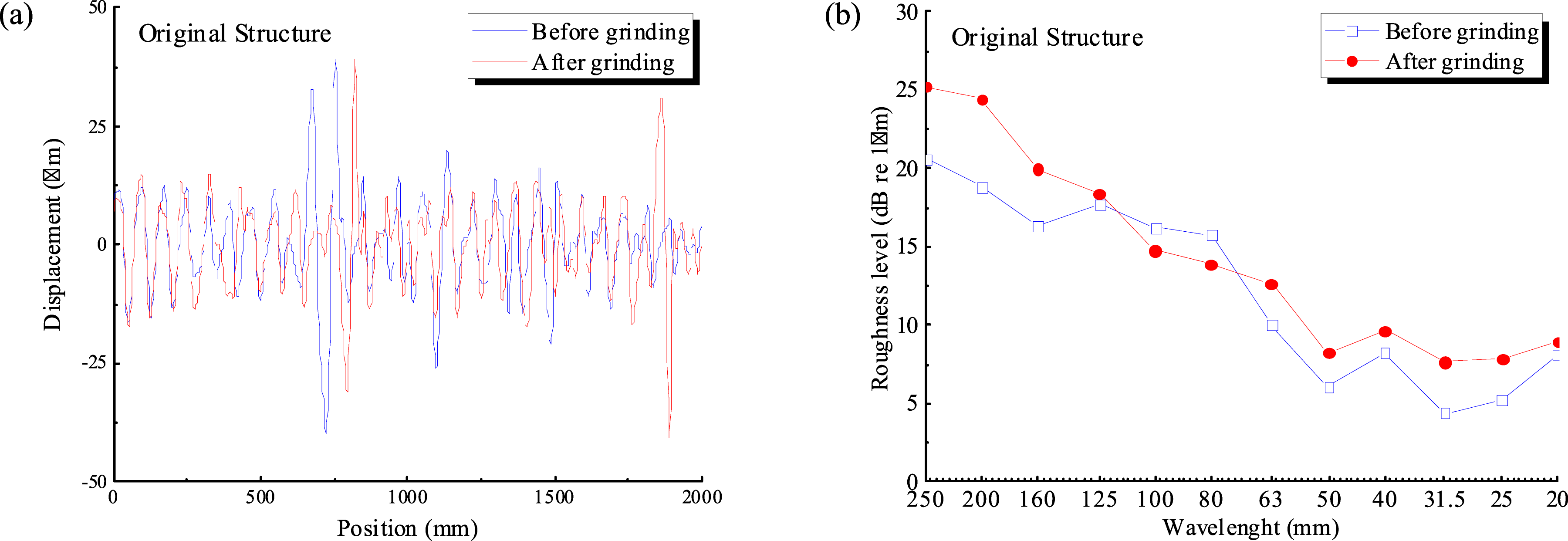
Figure 11(a) and 11(b) illustrate the rail roughness levels before and after grinding for the improved rail grinder, with the data also undergoing a band-pass filtering process between 30 and 100 mm. From the spatial characteristics of corrugation (Figure 11(a)), it is evident that the amplitude of rail irregularity has been significantly reduced after grinding. The one-third octave band diagram (Figure 11(b)) further indicates that, except for a few wavelengths where roughness levels increased slightly compared to pre-grinding, the roughness levels at most other wavelengths have undergone notable improvement. For the characteristic wavelength, the roughness level has decreased from 19.8 dB before grinding to 15.3 dB after grinding, representing a reduction of 22.6%. This enhanced grinding effect was 1.9 times that of the original structure. It is worth noting that, despite the improvements, irregularities corresponding to the wavelength will still persist on the rail surface after grinding. This is because the grinding principle of the enhanced rail grinder has remained unchanged, and the 60 Hz excitation source continues to be present. Comparison of rail surface roughness before and after grinding using a grinding carriage with an improved structure: (a) spatial characteristics of corrugation and (b) frequency domain characteristics of corrugation.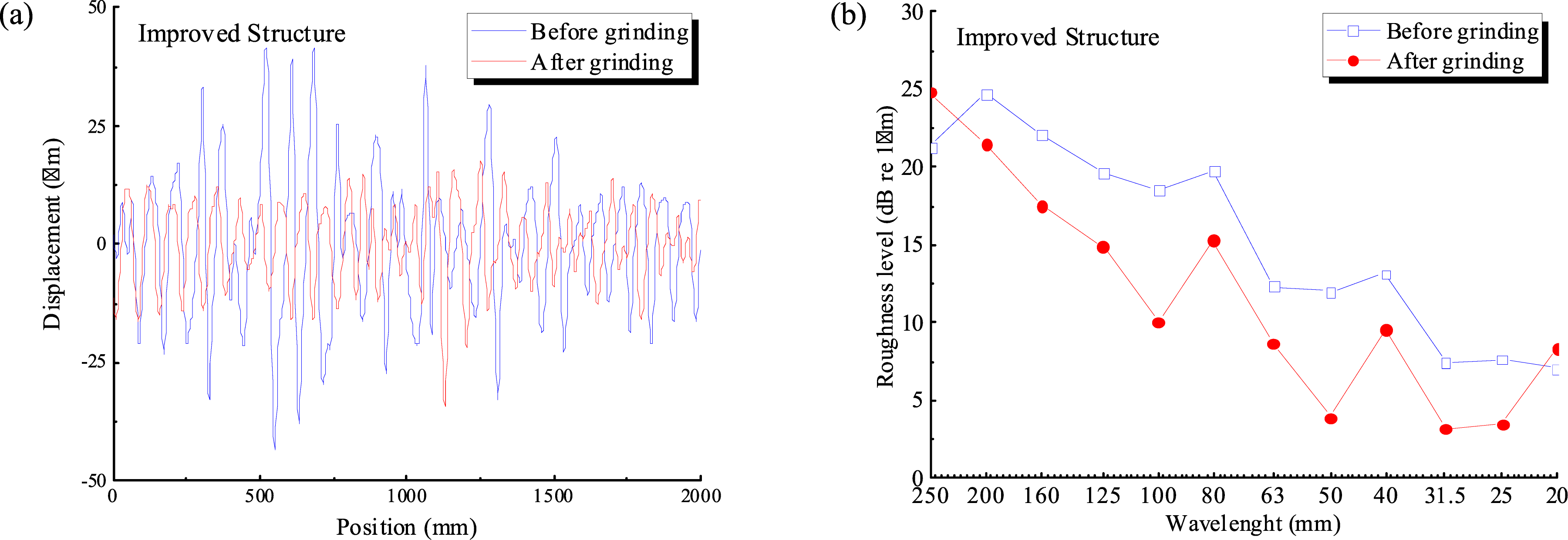
4. Conclusions
Addressing the issue of corrugation caused by residual periodic grinding marks generated during rail grinding, this paper aims to reduce the residual roughness level of rail grinding and thereby enhance the overall grinding quality. The vibration behavior of the grinding carriage frame and its relationship with excitation frequencies can be clarified by conducting vibration characteristic tests on the key components of the rail grinder. Subsequently, an improvement of the frame was carried out through modal analysis, and the effectiveness of this improvement was evaluated through field tests. The findings can be encapsulated as follows: (1) Vibration tests revealed that upon the activation of the motor, the vibrations are primarily dominated by the motor’s rotational frequency of 60 Hz and its harmonics. When the grinding stone comes into contact with the rail, this vibration intensifies further, exhibiting a 43.9% increase compared to when the motor is idling. This amplification of periodic vibrations may induce a 60 Hz cyclic fluctuation in both the grinding stone and the resulting grinding force during the grinding process, ultimately compromising the quality of the rail grinding. This is also the primary reason for the residual periodic irregularities on the surface of the rail after grinding. (2) The force hammer tests revealed significant characteristic frequencies within the grinding carriage frame, ranging from 12 to 19 Hz and 59 to 63 Hz. Notably, the frequency range of 59 to 63 Hz is close to the rotational frequency of the grinding motor, which greatly increases the risk of resonance occurring between the motor and the frame, thereby exacerbating the vibrations stemming from the motor’s self-rotation. (3) Modal analysis of grinding carriage frame indicated that the natural frequencies of the longitudinal expansion and contraction of the primary longitudinal beams of the grinding carriage frame and rolling motion of the crossbeams were 57.6 Hz and 60.3 Hz, respectively, which coincide with the secondary peak range of 59∼63 Hz, which could amplify motor vibrations and deteriorate grinding quality. From the perspective of avoiding resonant, the structural improvement of the frame was conducted, and the frequency decreased to 52.2 Hz and 39.5 Hz, respectively. Furthermore, all other modal frequencies are significantly distant from the sensitive frequency of 60 Hz, effectively avoiding the range of resonant frequencies. (4) Field tests demonstrated that the grinding motor vibration amplitude of the original rail grinder, when operating under grinding conditions, experienced a significant increase of 425% compared to its idle state. In contrast, the vibration amplitude of the improved rail grinder rose by a mere 141%, and the vibration energy in the vicinity of 60 Hz has been substantially weakened. The vibration jump-up of the improved structure from idle condition to grinding condition decreased by 66% compared to that before structural improvement. Besides, following the implementation of the improved rail grinder, the roughness level at the characteristic wavelength has significantly decreased from 19.8 dB prior to grinding to 15.3 dB post-grinding, marking a reduction of 22.6%. Notably, this enhanced grinding effect was 1.9 times that of the original structure. Therefore, the improved grinding carriage frame can significantly alleviate the impact of resonance occurring between the motor and the frame and substantially improve the quality of rail grinding.
Footnotes
Author’s note
(1) The paper has not been published previously, that it is not under consideration for publication elsewhere, and that if accepted it will not be published elsewhere in the same form, in English or in any other language, without the written consent of the publisher. (2) The paper does not contain material which has been published previously, by the current authors or by others, of which the source is not explicitly cited in the paper.
Declaration of conflicting interests
The author(s) declared no potential conflicts of interest with respect to the research, authorship, and/or publication of this article.
Funding
The author(s) disclosed receipt of the following financial support for the research, authorship, and/or publication of this article: This work was supported by the National Natural Science Foundation of China (Grant No. 51775454), the Sichuan Science and Technology Program (No. 2024NSFSC0946), the Special Funding for Postdoctoral Research Project of Sichuan Province (No. TB2024032) and the Fundamental Research Funds for the Central Universities (No. 2682024CX024).
Data Availability Statement
Data will be made available on request.