






Abstract
Periodic Track Irregularities (PTI) are a significant and sensitive source of vehicle dynamic response. However, previous studies have mainly focused on how to address periodic irregularities themselves, with limited research on the dynamic response and vibration reduction effects of PTI excitation on conventional tracks and Steel Spring Floating Slab Tracks (SSFST). In order to better reveal the vibration reduction effect of SSFST under PTI excitation and the influence of SSFST parameters on vibration reduction, the PTI spectra of actual operating tracks were collected, and a vehicle track system dynamic model including subway vehicles and track structures was established. The vibration reduction mechanisms of SSFST and the effects of related parameters on vibration reduction under real PTI excitation were analyzed. The results show that: In simulation models and real experiment, the primary frequency of 2 Hz, indicated by modal analysis, is the characteristic fault frequency resulting from the coupled mode of bogie hunting and car body yaw; The lateral acceleration amplitude of the floating slab track model is reduced by 57.4% compared to the conventional track, demonstrating significant suppression of periodic irregularity excitation and effective vibration reduction for wheelsets, frames, and car bodies by absorbing excitation energy; The vibration reduction of the floating slab track is affected by fastener and isolator stiffness and damping, with fasteners having a greater influence. At 80 MN/m stiffness and 10–30 kN·s/m damping, the 2 Hz vibration amplitude drops by 56%–68%.
Keywords
1. Introduction
With the continuous increase of subway train mileage, the requirements for higher operating quality are becoming increasingly strict (Ding et al., 2023; Huo et al., 2024; Ren et al., 2024). To control vehicle-track vibration, various vibration-reducing track structures are widely used. Among these, Steel Spring Floating Slab Track (SSFST) is the most common in rail transit due to its excellent vibration reduction (Tang et al., 2024; Zhou et al., 2024). Many researchers have conducted extensive research on vibration reduction performance and structural parameters.
The SSFST system significantly reduces rail vibrations, especially in the 30–80 Hz range for low and medium frequency vibrations, which have a significant impact on the surrounding environment and buildings (Cui et al., 2022; Zhang et al., 2023). The SSFST system has nonlinear stiffness characteristics and is able to adapt to different load variations. As a result, SSFST can provide effective vibration damping under a wide range of operating conditions (Yang et al., 2025; Zou et al., 2022). Under the dynamic load of the train, the SSFST system can maintain stable vibration isolation performance, which is crucial for ensuring the safety and comfort of rail transit (Han et al., 2019). The failure of the isolator will have a significant impact on the safety and stability of vehicle operation. End failure will change the constraint state of the floating plate, causing local vibration and reducing damping effect, mainly within 10 Hz (Zhao et al., 2022).
In damping track parameter research, the focus is on analyzing vibration characteristics. Firstly, simulation methods are used to study the physical behavior of damping track systems, providing a theoretical basis for optimization (Lei and Jiang, 2016; Li et al., 2022). Secondly, vehicle output results and structural vibration characteristics are analyzed to understand dynamic behavior and optimize design (Li et al., 2024a); finally, on-site experiments verify the impact of parameter changes, confirming the research method’s validity and supporting theoretical model improvement (Zhou et al., 2022).
Track irregularities significantly impact vehicle dynamics and are extensively studied. They are mainly categorized into vertical irregularities (Zhao et al., 2023), horizontal irregularities and composite irregularities (Dere, 2016). For smooth operation, a vehicle-bridge coupling system is established, with the main beam’s deformation serving as an input for track irregularities. The safety of train operation is evaluated by calculating the dynamic response of bridges and analyzing safety standards (Luo et al., 2022; Peng et al., 2024). Besides smooth operation research, previous studies have also detailed the impact of track irregularities on normal vehicle operation (Faccini et al., 2025; Song et al., 2023).
Periodic Track Irregularities (PTI) significantly impact vehicle dynamics. A subway line in China experienced low-frequency lateral displacement due to track periodic excitation. On-site investigations clarified the formation mechanism of abnormal vehicle vibrations, with the vehicle body’s main vibration frequency around 2 Hz (Li et al., 2024b). A 3D wear model was established and wear simulations for PTI were conducted, studying the dynamic response of PTI at different wear stages to subway vehicles (Wen et al., 2024). Previous researchers have extensively studied PTI’s impact on subway vehicle operation (Choi et al., 2013; Xin et al., 2019). Existing studies have not yet fully revealed two key issues: first, the vibration energy dissipation mechanism of steel-spring floating-slab roadbed (SSFST) under the excitation of track irregularity (PTI) induced by subway vehicle operation; and second, the influence of the variation of structural parameters of SSFST on the efficiency of its vibration transmission in suppressing PTI.
This article explores the dynamic response and vibration reduction of subway vehicles on SSFST under PTI excitation. The article is organized as follows: Chapter 2 details the construction of the rigid-flexible coupling model for urban rail vehicles’ SSFST and verifies the simulation model’s reliability using actual track roughness data; Chapter 3 uses simulation to verify SSFST’s damping effect on PTI, studies the vibration transmission path of SSFST under PTI excitation, and analyzes the damping effect of SSFST fasteners and isolators with different parameters; finally, the conclusion is presented and discussed in Chapter 4.
2. Model establishment
2.1. Vehicle-track coupled dynamics model
The 3D Vehicle Track Coupled Dynamics (VCTD) model includes two key subsystems: vehicle, track, and wheel-rail interaction. We developed the VTCD model to more accurately simulate wheel-rail interaction under actual operating conditions.
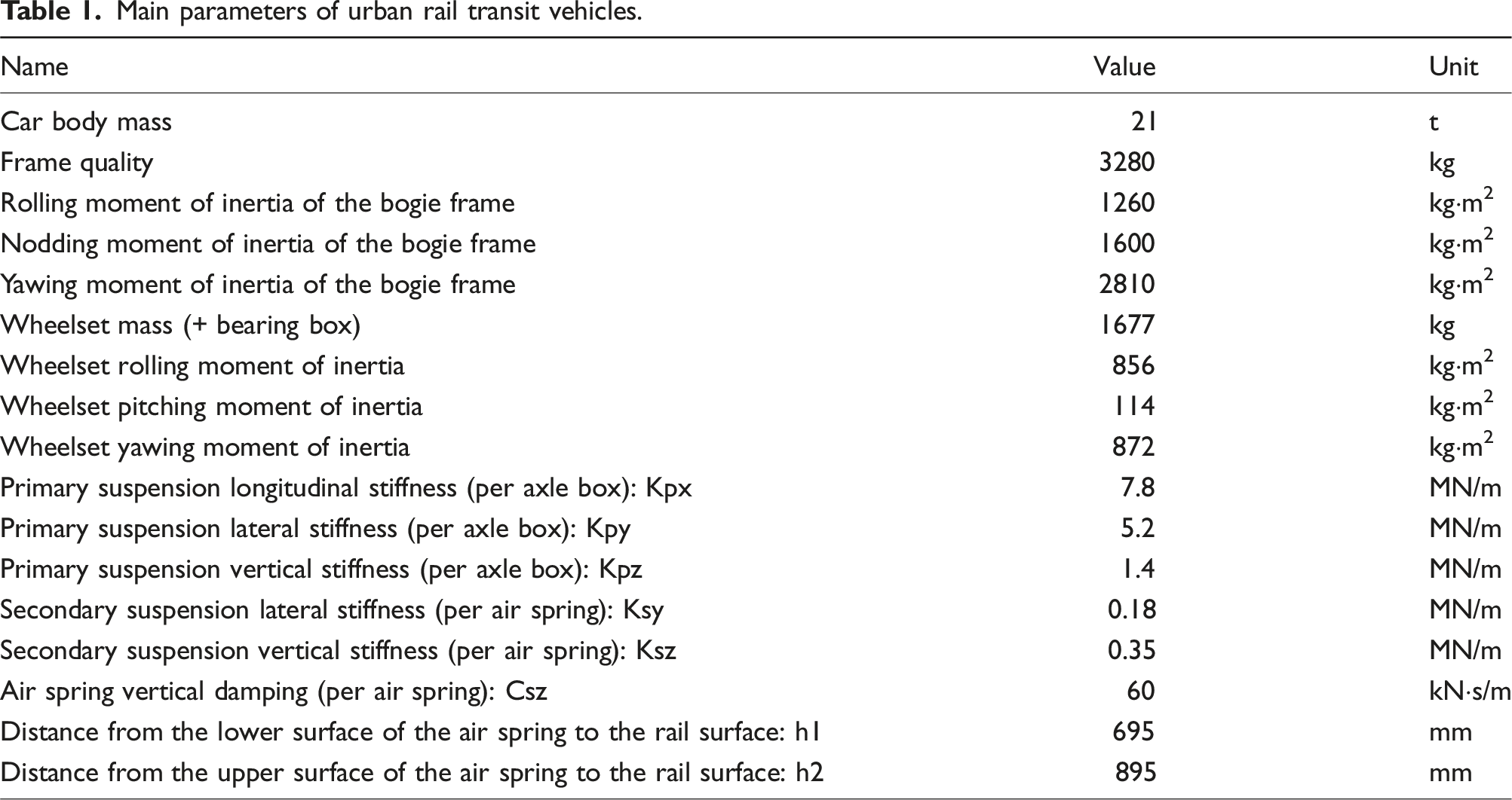
This article presents a dynamic rail vehicle model comprising a car body, two bogies, four wheelsets, and suspension systems. The car body and wheelsets connect to their respective bogies through secondary and primary suspensions. Utilizing multi-body dynamics, each component is modeled as a rigid body with spring-damper elements representing both suspension stages. Nonlinearities in dampers and lateral stoppers are incorporated, resulting in a 42-degree-of-freedom mass-spring-damper system that accounts for vertical, lateral, roll, yaw, and pitch motions. We created an urban rail train model matching actual operating conditions, as shown in Figure 1(a) and (b). Main parameters of a type B metro train in operation are presented in Table 1. (a) The dynamic vehicle model; (b) vehicle dynamic model topology map. Main parameters of urban rail transit vehicles.
Hertz theory (Piotrowski and Kik, 2008) a classical wheel-rail contact theory, is widely used for its reasonable accuracy in determining contact spot geometry and pressure distribution. We apply Hertz theory to solve the wheel-rail contact problem and use the Fastsim method for the tangential contact issue.
Hertz contact theory assumes that the wheel-rail contact spot is elliptical. According to the assumption that elasticity and electrostatic potential problems are similar, the compressive stress in the elliptical contact spot can be regarded as changing according to the coordinates of the height of the semi ellipsoid, so the distribution of compressive stress in the contact spot can be expressed as
For the tangential contact problem, Fastsim algorithm (Piotrowski and Chollet, 2005) is used. The normal stress distribution in this algorithm differs from the semi-ellipsoidal distribution in Hertz theory. Applying Hertz theory’s normal stress distribution to the Fastsim algorithm would result in substantial errors. Therefore, Kalker derived a suitable formula for calculating normal stress, which corresponds to the Fastsim algorithm.
To calculate the shear stress and sliding velocity distributions in the contact spot, it is discretized into multiple elements with consistent compressive stress, shear stress, and sliding velocity parameters. Literature (Nielsen, 2009; Polach, 2021) suggest dividing the contact spot into 10 × 10 units to distinguish the adhesive zone, creep zone, compressive stress, and shear stress distributions.
2.2. Flexible track-floating slab coupled dynamics model
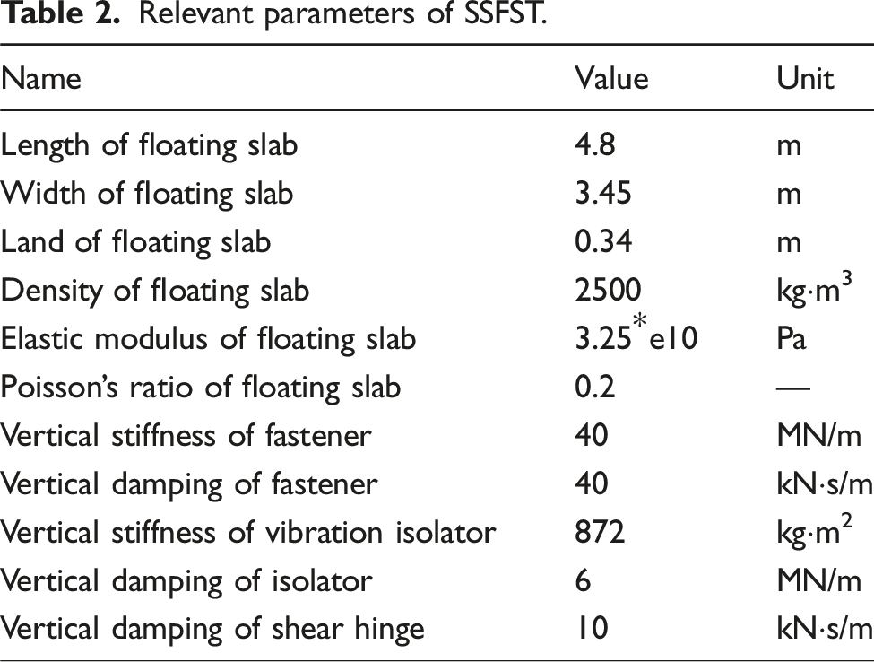
In the rigid-flexible coupling model, the addition of flexible body greatly increases the degree of freedom of the system, which brings great difficulties to the simulation calculation. The substructure analysis method effectively solves the calculation problem of the dynamic model. Through the Fembs interface between ANSYS and ANSYS, the application of flexible body in dynamic modeling is realized. Referring to the data in article (Ji et al., 2025) three 4.8 m prefabricated Floating Slabs and 21 m flexible tracks are established and connected by shear hinges. The specific process of system elasticity is shown in Figure 2. (Table 2) SSFST modeling process. Relevant parameters of SSFST.
2.3. Vehicle model verification
The data collection focused on an urban rail transit vehicle under empty load (AW0). The vehicle’s bogie system, includes the frame, dual wheelsets, primary/secondary suspension systems, and lateral dampers. The test used ATO (Automatic Train Operation) for round-trip running on the subway main line, with the train stopping at each station and doors closed during operation.
To collect lateral acceleration data, a multi-channel data acquisition system was employed, with acceleration sensors installed on the axle box, bogie frame, and vehicle bottom. The system and the sensor layout are detailed in Figure 3(a). The vehicle body acceleration signal is acquired at a frequency of 5000 Hz, and the signal is processed by means of low-pass filtering. Vertical and lateral acceleration sensors were placed at the stability measurement points at the a1 and a2 ends. (a) Acceleration collection systems; (b) rail geometry inspection systems.
This study investigates vibration mitigation mechanisms and dynamic responses of urban rail transit on SSFST under periodic track irregularities using a track inspection vehicle. The measurement system integrates six key elements: laser cameras, inertial sensors, photoelectric encoders, control cabinets, signal processors, and data processors. Employing inertial reference-based non-contact measurements, it collects track geometry data at 250 mm intervals with meter-precision mileage markers. The inertial reference measurement method and track geometry dynamic acquisition system are shown in Figure 3(b). The collected data is presented in Figure 4(a)–(d). (a) Left rail vertical irregularity; (b) left rail alignment irregularity; (c) right rail vertical irregularity (d) right rail alignment irregularity.
To further validate the urban rail vehicle model from section on Vehicle-track coupled dynamics model, we measured the train body’s lateral vibration acceleration during operation using comprehensive track detection. We imported the collected track spectrum data into the model for simulation. By comparing simulation results with actual data, we assessed the model’s accuracy and reliability. Using the track spectrum as input, we performed dynamic analysis with the urban rail vehicle model to obtain system response data and frequency-domain diagrams. The simulation results are shown in Figure 5. The simulated signal is also sampled at 5000 Hz. (a) Time-domain comparison; (b) frequency-domain comparison.
By comparing time-domain and frequency-domain graphs, the simulated and measured signals show significant consistency in both waveforms and characteristic frequency distributions, with the main frequency component stable in the 1.5–2 Hz band. This verifies the model’s accuracy in representing system dynamics under actual track excitation. The main frequency of the simulation model and the actual acquired signal model are the same, but the amplitude of the simulation model is 52% of the actual amplitude, but it is basically the same as the actual signal in the overall signal composition.
The validation results provide a theoretical basis for the construction of the rigid-flexible coupling dynamic joint simulation model of the track-floating slab, and can further study the vibration response and frequency transfer characteristics of the track foundation coupling system.
3. Analysis of vibration reduction mechanism
3.1. Analysis of SSFST model results
Modal analysis showed both SSFST and VCTD models share a vibration-prone 2 Hz bogie hunting/body yaw coupling mode (modal damping 0.046). In-phase bogie meandering combines with opposing body sway, creating synchronized track forces due to wavelength matching vehicle dimensions. This induces uniform rail wear and alternating side wear patterns.
The SSFST and normal rail vehicle models were simulated at 90 km/h. Given the rigid-flexible coupling part is set 100 m from the start, the lateral acceleration of the vehicle body between 3.5 s and 4.9 s in both simulations was compared, with results shown in Figure 6(a). (a) Time-domain comparison; (b) frequency-domain comparison.
Figure 6(b) shows the rigid-flexible coupling model has lower lateral acceleration amplitudes than the normal track model. The 2 Hz characteristic frequency of periodic irregularity fault has decreased by 57.4%, indicating SSFST can significantly reduce PTI excitation effects on trains.
Two simulations investigated SSFST’s lateral vibration control. First: Rigid-flexible floating-slab model compared excitation versus no-excitation conditions to assess SSFST equipment’s lateral response. Second: Compared conventional track with SSFST to study vehicle damping effects on periodic irregularity transmission while monitoring equipment lateral dynamics.
3.2. Mechanisms of vibration reduction in SSFST model
Conventional vibration damping is usually effective at frequencies
Simulation results in Figure 7(a) and (b) show significant differences in the floating-slab’s vibration response under excited and unexcited conditions. Time-frequency analysis indicates higher amplitudes under excitation, with the amplitude-frequency plot showing increased amplitudes in the 30–40 Hz range but not near 2 Hz. (a) Float slab time-domain comparison; (b) float slab frequency-domain comparison; (c) rail fastener time-domain comparison; (d) rail fastener frequency-domain comparison; (e) inter slab shear hinge time-domain comparison; (f) inter-slab shear hinge frequency-domain comparison; (g) VCTD PSD comparison; (h) float slab PSD comparison; (i) rail fastener PSD comparison; (j) inter-slab shear hinge PSD comparison.
Figure 7(c) and (d) illustrate rail fastener vibration responses, where excitation leads to higher amplitudes across most frequency bands, except for a slight reduction near 2 Hz. Shear hinges between floating slabs, shown in Figure 7(e) and (f), also exhibit amplified vibrations in the 20–40 Hz range under excitation, with no significant activity near 2 Hz.
Figure 7(g) compares the PSD of the system with and without SSFST, showing reduced amplitude around 2 Hz. Figure 7(h) confirms energy absorption by the floating slab, with increased amplitudes in the 30–70 Hz range. Amplitude-frequency plot analysis confirms that PTI excitation doesn’t resonate with urban rail vehicles.
PSD analysis in Figure 7(i) and (j) suggests SSFST mitigates PTI-induced vibrations by redistributing excitation energy rather than direct damping. All SSFST components show increased energy absorption, effectively dissipating PTI energy. Thus, the steel-spring floating slab offers excellent buffering against PTI excitations.
3.3. Mechanisms of vibration reduction in VCTD model
Figure 8(a) and (b) shows the subway frame’s vibration response, clearly different between tracks with and without SSFST. The track without SSFST has significantly higher vibration amplitudes in the time-frequency diagram, and at 2 Hz, the amplitude is 68.8% higher than that of the track with SSFST. (a) Frame time-domain comparison; (b) frame frequency-domain comparison; (c) wheel sets time-domain comparison; (d) wheel sets frequency-domain comparison; (e) secondary suspension time-domain comparison; (f) secondary suspension frequency-domain comparison; (g) the primary suspension time-domain comparison; (h) the primary suspension frequency-domain comparison.
Figure 8(c) and (d) depict the vibration response of urban rail transit wheelsets, also showing a significant difference between tracks with and without SSFST. The track without SSFST has much higher vibration amplitudes in the time-frequency diagram, and at 2 Hz, the amplitude is 62.4% higher than that of the track with SSFST.
Figure 8(e) and(f) illustrate the lateral dynamic response of the train’s secondary suspension. The vibration response differs between tracks with and without SSFST. In the time-frequency diagram, the track without SSFST has slightly higher vibration amplitudes, and at 2 Hz, the amplitude is only 8% higher than that of the track with SSFST.
Figure 8(g) and (h) show the lateral dynamic response of the train’s primary suspension. There is no significant difference in vibration response between tracks with and without SSFST. In the time-frequency diagram, the track without SSFST has slightly higher vibration amplitudes, and at 2 Hz, there is no significant difference in amplitude.
In summary, periodic irregularities are transmitted from wheel-rail contact through the primary suspension, frame, secondary suspension, to the car body. The SSFST significantly reduces vibrations in wheelsets, frames, and car bodies, but has limited damping effect on the secondary suspension and minimal impact on the primary suspension. Overall, it effectively mitigates the impact of periodic irregularity excitation on the lateral vibration acceleration of vehicle components, indicating propagation through the vehicle-track interaction chain.
4. Parametric effects on SSFST dynamic response under PTI excitation
SSFST are key for urban rail transit vibration reduction, with fastener stiffness and damping being crucial factors.
4.1. Different stiffness for SSFST
The study investigated the impact of fastener stiffness on the vibration reduction of the floating slab, with the fastener and isolator stiffness as the independent variable. Five working conditions with isolator stiffness of 1 MN/m, 12 MN/m, 14 MN/m, and 18 MN/m were simulated at 90 km/h. Figure 9(a) shows that changing isolator stiffness had little effect on track lateral vibration acceleration amplitude (max difference <3%), but increasing stiffness from 1 MN/m to 18 MN/m reduced the amplitude fluctuation range by ∼35%, showing improved system stability with higher stiffness. Figure 9(b)’s frequency-domain analysis shows that under periodic irregularity excitation, the amplitude-frequency characteristics of each condition were similar, but at the 2 Hz characteristic frequency, when the isolator stiffness reached 18 MN/m, the vibration amplitude was 52% lower than the reference condition (1 MN/m), indicating a positive correlation between stiffness and amplitude reduction. This shows that increasing isolator stiffness can suppress specific low-frequency vibrations while maintaining system control over broadband vibrations. (a) Vehicle body acceleration under different stiffness isolator conditions time-domain comparison; (b) vehicle body acceleration under different stiffness isolator conditions frequency-domain comparison; (c) vehicle body acceleration under different stiffness fastener conditions time-domain comparison; (d) vehicle body acceleration under different stiffness fastener conditions frequency-domain comparison.
Five working conditions with fastener stiffness of 20 MN/m, 40 MN/m, 60 MN/m, 80 MN/m, and 100 MN/m were simulated at 90 km/h. Figure 9(c) shows the time-frequency diagram for six conditions, revealing different effects of fastener stiffness on lateral vibration acceleration amplitude. Amplitudes were similar for 20 MN/m, 80 MN/m, and 100 MN/m, with clear differences at 40 MN/m and 60 MN/m, and all five conditions differed from the normal track. Figure 9(d) shows the amplitude-frequency diagram for six conditions, indicating significant impact of fastener stiffness on periodic irregularity amplitude. Calculations show that at 20 MN/m, 80 MN/m, and 100 MN/m, the 2 Hz fault frequency was reduced by 56.4%, 56.8%, and 57.2% respectively, while at 40 MN/m and 60 MN/m, it was reduced by 54.2% and 55.1%, indicating that 80 MN/m fastener stiffness is appropriate.
4.2. Different damping for SSFST
The study examined the impact of fastener and isolator damping on the vibration reduction of the floating slab, with the damping of different fasteners and isolators as the independent variable. The track isolator stiffness was set at 20 kN·s/m, 40 kN·s/m, 60 kN·s/m, 80 kN·s/m, and 100 kN·s/m, simulated at 90 km/h. Figure 10(a) shows that different isolator damping had almost no effect on the amplitude of lateral vibration acceleration during train operation. Figure 10(b) shows the amplitude-frequency diagram for five conditions, indicating that different isolator stiffness had no obvious effect on PTI amplitude. Calculations show that the 2 Hz fault frequency was reduced by about 52%, with greater isolator damping leading to more amplitude reduction. (a) Vehicle body acceleration under different damping isolator conditions time-domain comparison; (b) vehicle body acceleration under different damping isolator conditions frequency-domain comparison; (c) vehicle body acceleration under different damping fastener conditions time-domain comparison; (d) vehicle body acceleration under different damping fastener conditions frequency-domain comparison.
Five working conditions with fastener damping of 20 kN·s/m, 40 kN·s/m, 60 kN·s/m, 80 kN·s/m, and 100 kN·s/m were simulated at 90 km/h. Figure 10(c) shows that different fastener damping had varying effects on lateral vibration acceleration amplitude, with the smallest variation at 10 kN·s/m and increasing variation with higher damping. Figure 10(d) shows the amplitude-frequency diagram for five conditions, indicating significant impact of fastener damping on periodic irregularity amplitude. Calculations show that at 10 kN·s/m, the 2 Hz fault frequency was reduced by 68.4%, but increased significantly with higher damping, reducing to only 34.2% at 120 kN·s/m. Therefore, the optimal damping range is 10 kN·s/m–30 kN·s/m, which significantly reduces periodic irregularity excitation.
Under PTI excitation, both the stiffness and damping of isolators and fasteners in SSFSTs significantly affect vibration reduction. Compared to isolators, fastener stiffness and damping have a greater impact. Specifically, the best vibration reduction is achieved when fastener stiffness is 20–60 MN/m and damping is 10–30 kN·s/m.
5. Conclusion
This study reveals the vibration characteristics of subway trains under periodic track upset (PTI) and the vibration damping mechanism of steel-spring floating-slab track (SSFST), and the main innovative findings are as follows: (1) A coupled dynamics model containing vehicle, track, and wheel-rail contact is developed and verified by measured data, providing an effective tool for PTI working condition analysis. (2) 2 Hz bogie serpentine/vehicle headshake weakly damped coupled mode (damping ratio 0.046) is found. Compared with ordinary rail, SSFST reduces the lateral vibration of the car body by 57.4% at the eigenfrequency, confirming its PTI vibration suppression advantage. (3) SSFST absorbs/disperses PTI energy through the floating plate-fastener-hinge system, effectively blocking the resonance transmission. The vibration transmission path from the wheel rail to the frame is significantly damped, but the vibration damping effect of the second suspension system is limited, which reveals the vibration attenuation characteristics of the system in a “top-down” manner. (4) 80 MN/m fastener stiffness with 10–30 kN·s/m damping vibration damping is optimal. The stiffness of the vibration isolator mainly affects the stability of the system, while the fastener parameters play a dominant role in the control of low-frequency PTI.
In this paper, the dual damping mechanism of parameterized SSFST in PTI spectral excitation is systematically revealed for the first time through the coupled analysis of vehicle-PTI-SSFST dynamic interactions, which fills the gaps in the research on the correlation between vibration mechanism and parameter optimization in this field.
Footnotes
Declaration of conflicting interests
The author(s) declared no potential conflicts of interest with respect to the research, authorship, and/or publication of this article.
Funding
The author(s) disclosed receipt of the following financial support for the research, authorship, and/or publication of this article: This paper is supported by Beijing Natural Science Foundation (L241033) and National Natural Science Foundation of China (52272385), (51975038), (52205083), (52305090), (52475085).
