
Abstract
Hydro-pneumatic suspension is widely used for its desirable nonlinear stiffness and damping characteristics. However, with the presence of parameter uncertainties and inherent nonlinearities, traditional controllers often yield unsatisfactory control effects in practical applications. Therefore, a novel stability control method for active hydro-pneumatic suspension is proposed in this paper. First, a nonlinear mathematical model of the hydro-pneumatic suspension considering the seal friction and a full vehicle dynamics model is established. Second, the vertical, roll, and pitch motions of the vehicle body are collaboratively controlled by establishing three active disturbance rejection sliding mode controllers (ADRSMC) in parallel with each other. The lumped disturbances caused by the model nonlinearities and uncertainties are estimated by the extended state observer (ESO), integrating these into the sliding mode control (SMC) law to enable adaptive system response. Finally, the effectiveness of the proposed control method is verified under the bump and random road surfaces. The results demonstrate that the proposed ADRSMC has better performance than the ADRC method and SMC, significantly improving the vehicle stability.
Keywords
1. Introduction
The suspension system is crucial for maintaining vehicle stability and isolating road-included impacts, directly influencing safety and ride comfort. Traditional passive suspensions have fixed damping and stiffness coefficients, which limit their ability to adapt to varying road surface and only suppress vehicle vibrations by optimizing specific parameters. In contrast, modern controllable suspensions can dynamically adjust stiffness and damping coefficients based on road conditions and vehicle status, providing superior vibration reduction.
Currently suspension control algorithms primarily include PID (Li et al., 2024), SMC (Qing et al., 2020), backstepping control (Sun et al., 2012), fuzzy control (Yuan et al., 2023), and output feedback control (Li et al., 2019). Many scholars have improved and optimized the above algorithms recently. Li et al. (2024) combined fractional-order theory with traditional PID control to proposed a semi-active suspension control strategy. Rath et al. (2020) proposed a robust constrained output feedback method using sliding mode controller for nonlinear active suspension systems with hydraulic actuators, improving the performance under the parameter uncertainties and sensor noise. Pang et al. (2019) developed a constrained adaptive backstepping tracking controller using Lyapunov stability theory to stabilize the vertical and pitching motions. Li et al. (2018) proposed an adaptive event-triggered fuzzy control method, which conserves resources compared to traditional fixed-threshold mechanisms. Shao et al. (2019) developed an output feedback H∞ controller to address actuator failure and time delay in electric vehicle active suspensions with wheel motors, achieving exceptional performance.
Among the mentioned algorithms, the excellent ability to handle uncertainty and disturbances makes SMC an essential tool for solving complex control problems (Deshpande et al., 2014, 2019; Ho et al., 2021; Pusadkar et al., 2019). For instance, Wen et al. (2016) proposed a fuzzy dynamic sliding mode method to address the uncertainties in active suspension systems, validating the effectiveness based on a quarter vehicle model. Bai and Wang (2021) combined linear quadratic regulator (LQR) optimal control with SMC, proposing a robust optimization control strategy for vehicle active suspension systems. Simulation results confirm its robust to parameter uncertainties and external disturbances. Lin et al. (2019) designed a fuzzy sliding mode controller to achieve nonlinear feedback decoupling control by estimating state variables and model uncertainties using a novel proportional differential sliding mode observer.
Hydro-pneumatic suspension system features high integration, substantial load-carrying capacity, and adjustable body height, making them extensively used in military and engineering vehicles. Semi-active and active control further optimize dynamic characteristic, offering significant application potential. Ren et al. (2016) proposed a sliding mode control method for semi-active hydro-pneumatic suspension using a state observer, achieving a balance between ride comfort and handling stability. Sim et al. (2017) developed a semi-active optimal control algorithm using the Linear Quadratic Gaussian (LQG) method for agricultural tractors, validating the simulation results through experiments. Guan et al. (2016) proposed a sliding mode force tracking control method for active hydro-pneumatic suspension. However, most existing control methods rely on linear approaches, which often overlook complex nonlinearities and uncertainties, thereby limiting control accuracy and effectiveness.
Yang et al. (2021) developed a semi-active hydro-pneumatic inerter-based suspension nonlinear model and proposed a two-stage hierarchical control strategy using model predictive control to reduce system calculations and hydraulic valve usage, thereby extending system life. Most of the above controller b require model-based design and depend on precise feedback signals, leading to significant performance degradation under nonlinear or uncertain disturbances. However, the ADRSMC control does not rely on an accurate mathematical model, and achieves precise system control by dynamically estimating and compensating for the lumped disturbances through the ESO. Chen et al. (2023) proposed a revised active disturbance rejection sliding mode control algorithm for active hydro-pneumatic suspension. Simulations showed that the algorithm significantly improves the vertical stability under the system disturbances and remains robust to parameter uncertainties. However, most research on hydro-pneumatic suspension control focuses on basic quarter suspension models, without considering vehicle pitch and roll motion.
To address the shortcomings of existing studies, a novel stability control method for active hydro-pneumatic suspension is proposed in this paper. First, a nonlinear hydro-pneumatic suspension mathematical model and a vehicle dynamics model is developed. The accuracy of the developed hydro-pneumatic suspension model is verified using published experimental data. Second, an ADRSMC is designed for the vertical, roll, and pitch motions of the body. The lumped disturbances caused by system nonlinearities and motion-state coupling are estimated by the ESO, while these disturbances are compensated by SMC law to achieve global optimization of vehicle performance. Finally, simulations and experiments on the bump and random road surfaces validate the effectiveness in enhancing vehicle stability of the proposed method.
2. System modeling
2.1. Mathematical model of hydro-pneumatic suspension
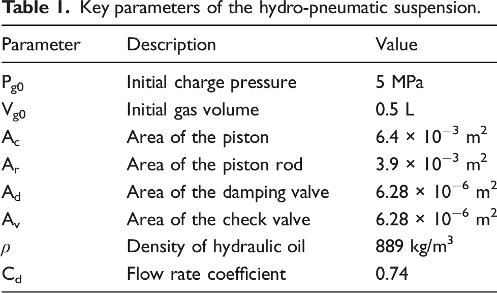
The simplified structure of the hydro-pneumatic suspension as shown in Figure 1, primarily consists of a piston, piston rod, and cylinder component. During the compression stroke, the nitrogen gas in the rodless chamber is compressed, generating a large elastic force. Conversely, during the stretching stroke, the volume of the rodless chamber increases, reducing the elastic force. At this time, the check valves close, decreasing the oil overflow area and generating a larger damping force to quickly attenuate vibrations. The key parameters of the hydro-pneumatic suspension are listed in Table 1. Structure diagram of the hydro-pneumatic suspension. Key parameters of the hydro-pneumatic suspension.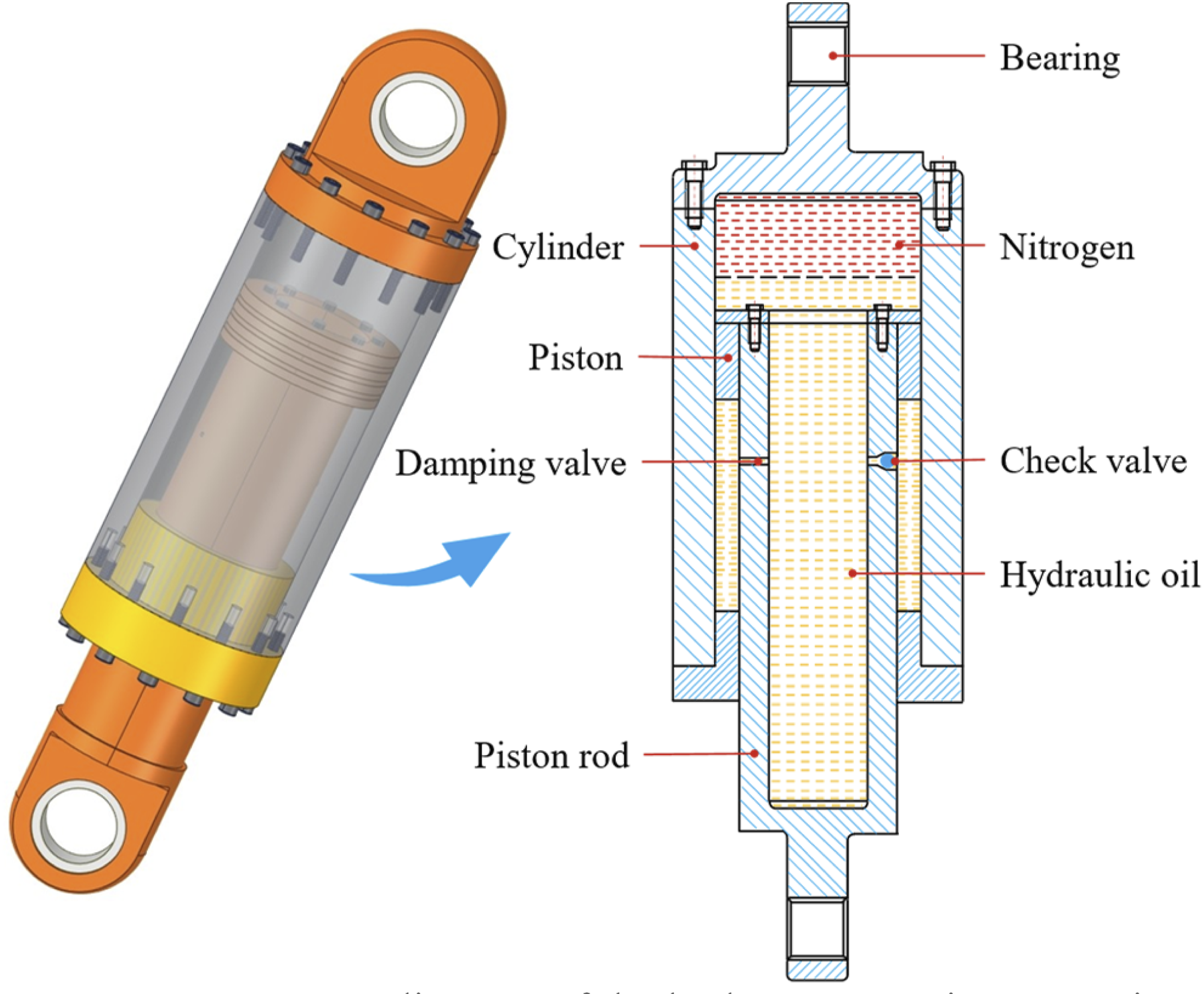
The dynamic characteristics of hydro-pneumatic suspension systems are influenced by factors such as operating temperature, and oil viscosity. To simplify the analysis, the following assumptions are made in this paper: (1) The oil temperature remains constant during stretching and compression. (2) The oil compressibility is disregarded, assuming constant oil volume and elastic modulus. (3) The instantaneous pressure is equal everywhere within the same chamber.
Based on the above assumptions, a nonlinear mathematical model of the hydro-pneumatic suspension is developed. The output force generated by the strut is:
2.1.1. Nonlinear stiffness model
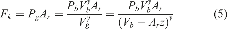
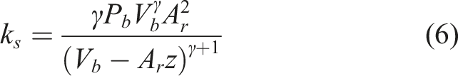
Hydro-pneumatic suspension typically uses nitrogen as the elastic medium. Given the low vibration frequency during operation, the temperature and pressure variations are relatively small. It can be considered that nitrogen has the same properties as ideal gas. Therefore, the pressure variation can be described by the ideal gas state equation:
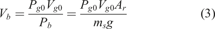
The change in the volume of gas in the accumulator is equal to the change in the volume of oil in the hydraulic cylinder. Therefore, the gas volume at any moment can be expressed as:
2.1.2. Nonlinear damping model
When fluid passes through a small orifice at high speed, a local pressure drop occurs due to the sudden decrease in cross-sectional area. According to the throttling theory of liquid passing through a thin-walled small orifice, the pressure drops across the orifice can be expressed as: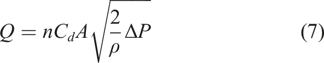
When the hydraulic cylinder and piston rod move at a relative velocity of 
The oil passes through the damping and check valves in the compression stroke. On the contrary, only the damping valve is passed in the tension stroke. Thus, the pressure drops across the damping and check valves can be obtained from equations (7) and (8) as follows: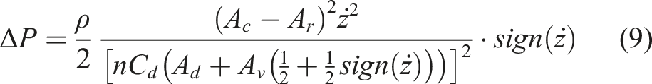
Therefore, the damping force of the hydro-pneumatic suspension can be expressed as: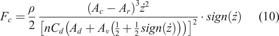
Similarly, the derivation of the above equation with respect to the piston rod velocity to get the damping coefficient as: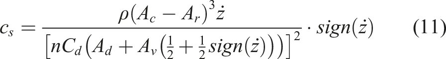
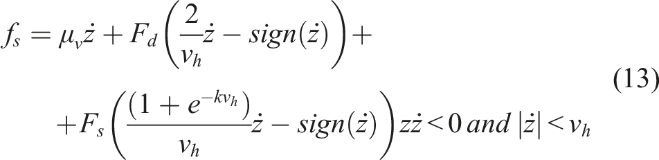
2.1.3. Seal friction model
Seal friction has a significant effect on the dynamic characteristics of the hydro-pneumatic suspension, which usually exhibits the combination of Coulomb friction, Stribeck friction and viscous friction during periodic motions. The magnitude of which is related to the velocity of the hydro-pneumatic suspension strut (Lin et al., 2020), as shown in Figure 2. Seal friction model of hydro-pneumatic suspension.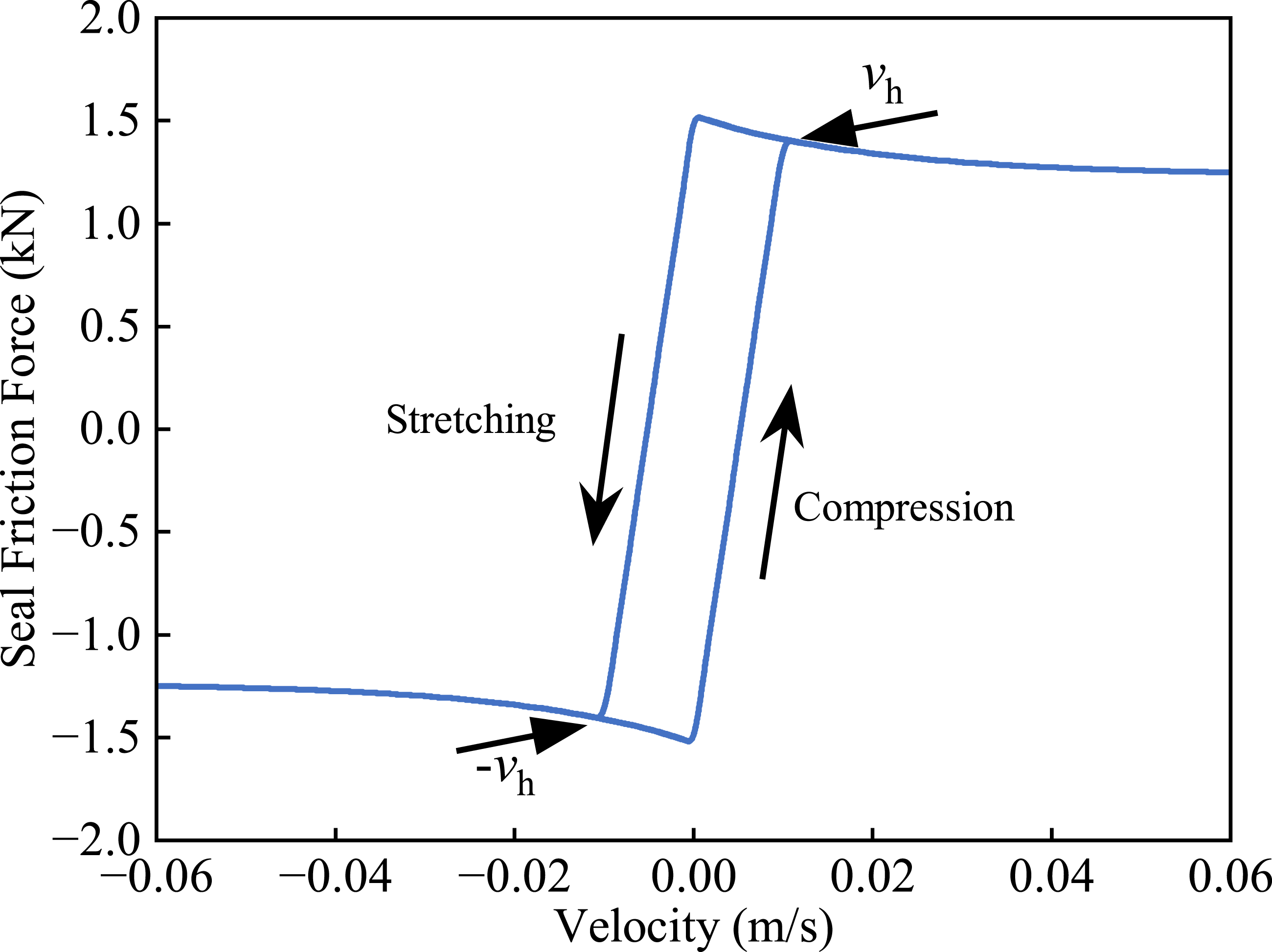
When the strut velocity exceeds the hysteresis transfer velocity 
2.2. Nonlinear characteristics verification
An accurate and reliable mathematical model of hydro-pneumatic suspension is essential for controller design. Previous studies have intensive studied the dynamic characteristics of hydro-pneumatic suspension through bench experiments to validate the accuracy of simulation models. Yin et al. (2018) conducted both quasi-static and dynamic experiments on hydro-pneumatic suspensions containing oil-gas emulsion. For the quasi-static tests, sinusoidal excitations with amplitudes of 25 mm and 50 mm were applied at a low frequency of 0.1 Hz. The dynamic tests employed higher frequencies of 1 Hz and 3 Hz with a constant amplitude of 7.5 mm. Due to the applicability of the experimental data and the consistency between the research object and the model developed in this study. We constructed a hydro-pneumatic suspension simulation model using the same parameters and compare it with the experimental results in the literature, as shown in Figure 3. Comparison between experimental measurements and simulation results.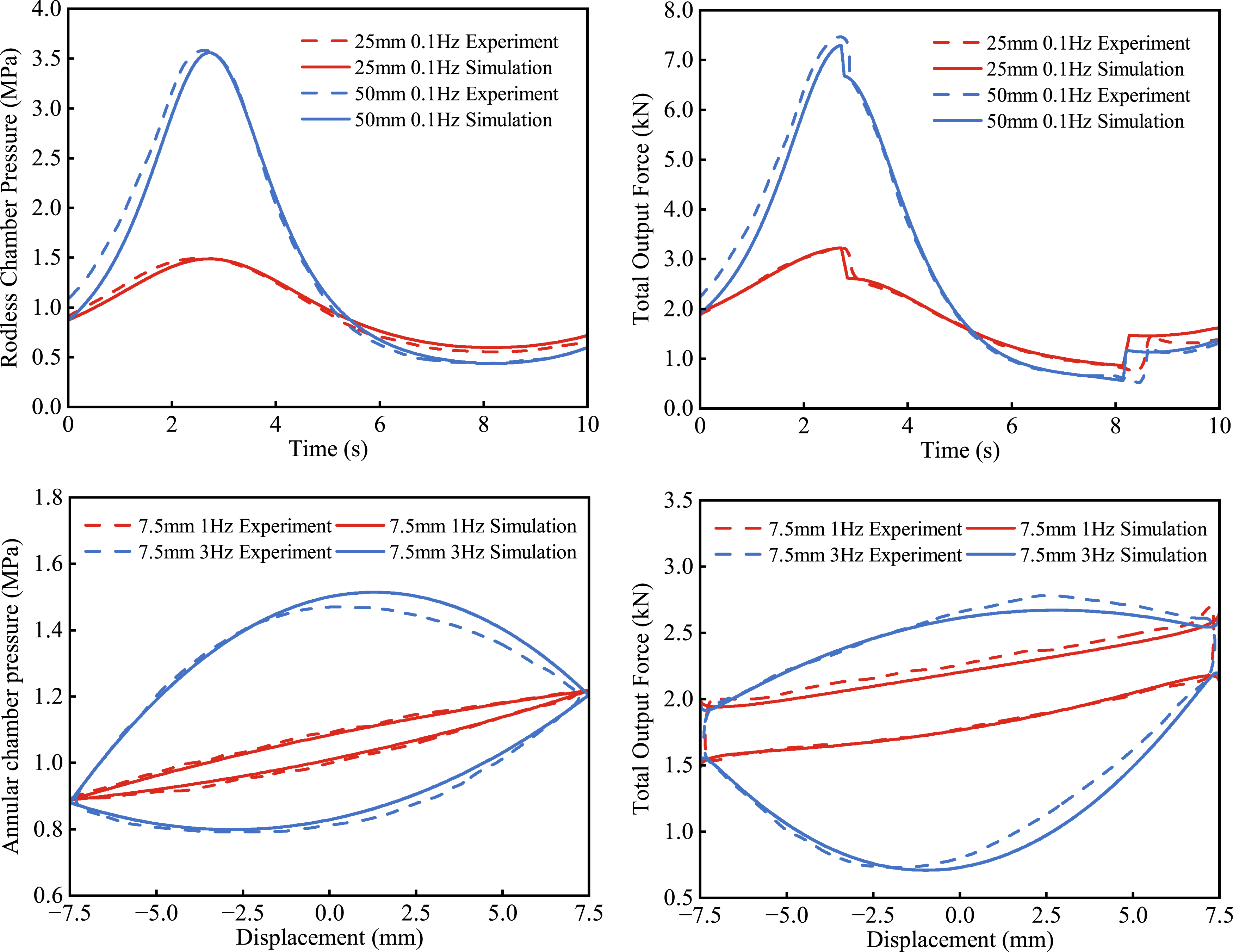
The simulation model developed in this study accurately replicates the force and pressure trends observed in the experiments. However, the adiabatic assumption in the model neglects the heat transfer effects present in the system. Under experimental conditions, the heat exchange between the oil-gas emulsion and the external environment affects the compressibility of the fluid and its response curve, leading to a certain hysteresis error under high-frequency excitation. Overall, the model reliably predicts the dynamic response of the hydro-pneumatic suspension, confirming its accuracy and reliability.
2.3. Vehicle dynamic model
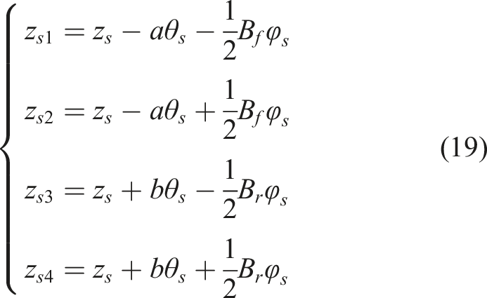
The seven-degree-of-freedom vertical dynamics model includes the vertical, roll, and pitch motions of the body and the vertical motion of the four unsprung masses. Figure 4 displays the established dynamics model for the full vehicle. Vehicle dynamics model.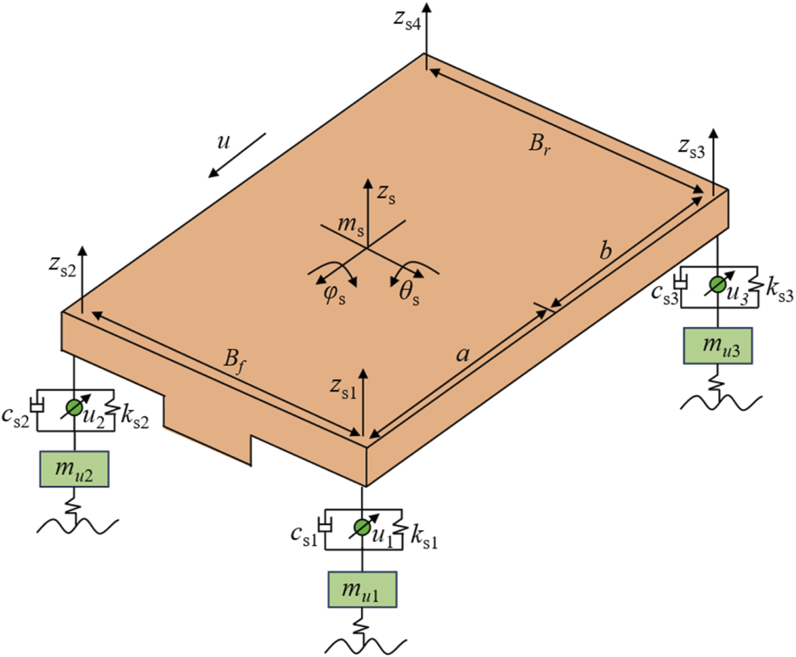
Define the subscripts 


The differential equations for the vertical motion of the unsprung mass are as follows:
The equivalent control force 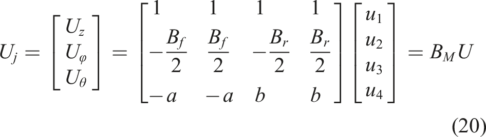
3. Control algorithm design
Both ADRC and SMC demonstrate strong robustness, effectively handling system uncertainties and external disturbances. These characteristics make them suitable for the design requirements of active hydro-pneumatic suspension systems. Based on the nonlinear model of the hydro-pneumatic suspension and the full vehicle dynamics model established in Section 2. The ADRSMC algorithms are designed for the vertical, roll, and pitch motions of the vehicle. Figure 5 shows the ADRSMC structure of the active hydro-pneumatic suspension system of the full vehicle. Structure diagram of the ADRSMC for the full vehicle.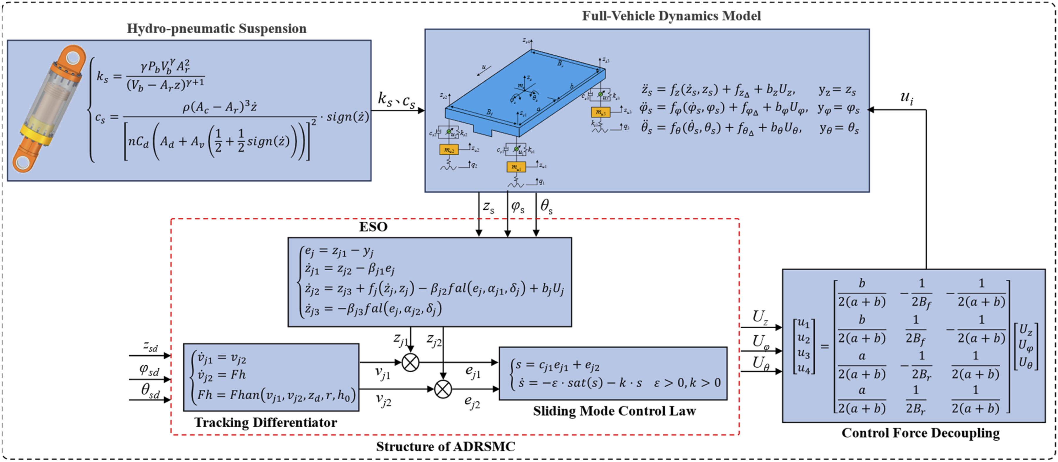
The vehicle generates vertical, roll, and pitch vibrations under road excitation. The ESO estimates the system state of the active hydro-pneumatic suspension, while the error between the estimated and expected vibration signals in each direction serves as input to the SMC law. The required equivalent control force for tracking the motion in each direction is calculated in real time by the sliding mode control law, which compensates for disturbances. The equivalent control forces are then decoupled to obtain the actual control forces corresponding to the four suspension subsystems.
The control objective is to make the vibration of the body in each direction tend to 0 (i.e., 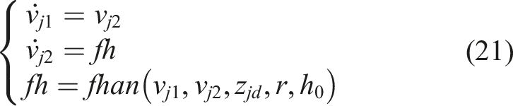
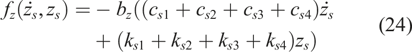
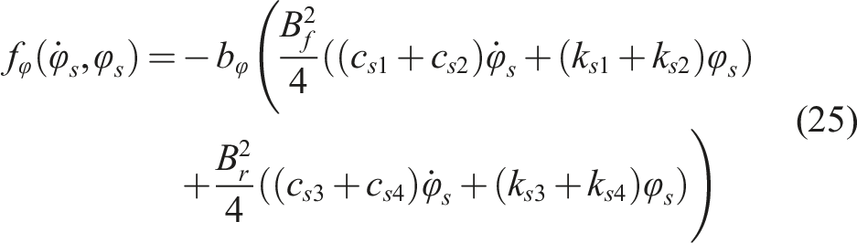
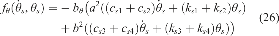
The motions of the vehicle in different directions exhibit complex coupling effects, where significantly influence system behavior. These coupling effects are incorporated into the total disturbance term, which is estimated for by the ESO. The differential equations for the vertical, roll, and pitch motions of the body are organized as follows: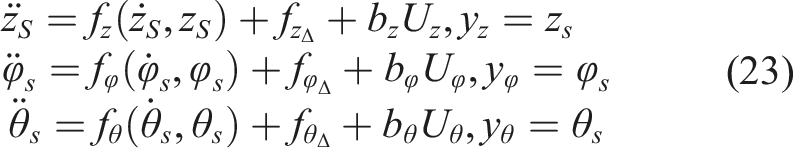
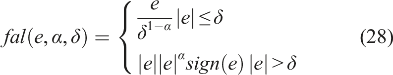
The ESO estimates and compensates for system disturbances in real time by expending the total disturbance into an additional state variable. Considering 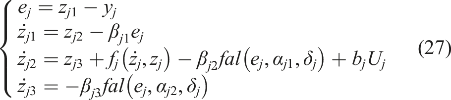
Define the error between the tracking values and observed values: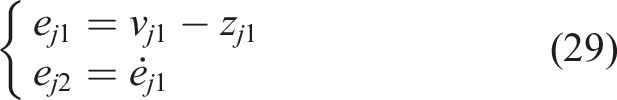
SMC law is used instead of the NLSEF in the ADRC endows the control system with the fast response capability of SMC and the high robustness and low jitter characteristics of ADRC.
According to the error model established in equation (29), the sliding mode surface is designed as follows:
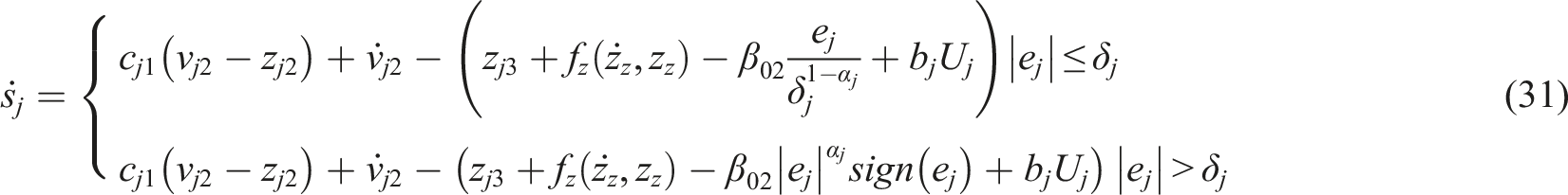
To enable the system state to reach the sliding mode surface in a finite time and ensure that the convergence process has good dynamic quality, it is necessary to choose a suitable convergence law 
Combining equations (31) and (32), the ADRSMC law can be expressed as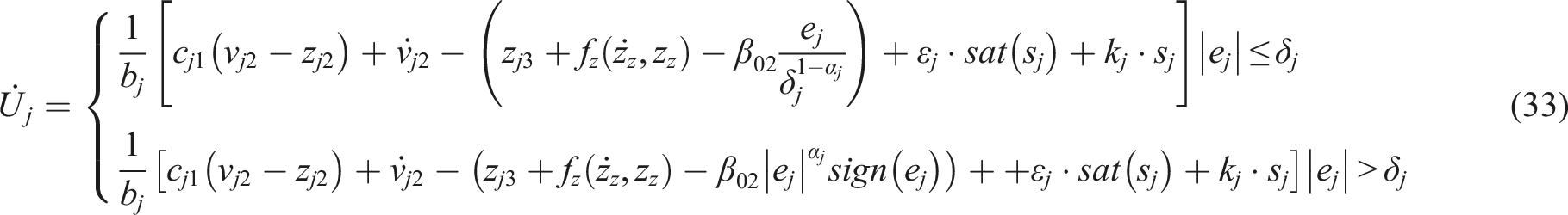
The variable structure characteristic of sliding mode control makes it a switching characteristic, which inevitably leads to the control system jitter in practical applications. To reduce the jitter phenomenon in sliding mode control, a saturation function is used instead of the sign function: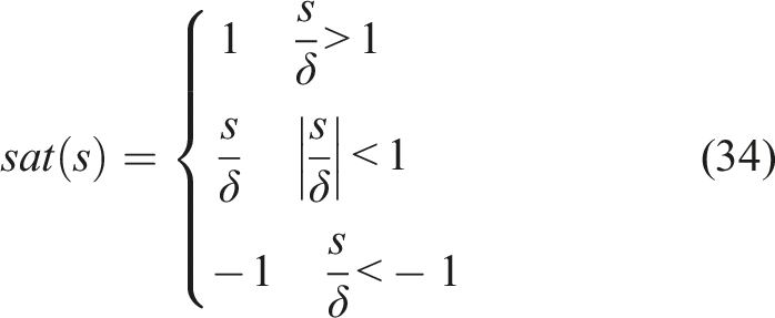

If the system output eventually remains bounded or converges to 0 after being subjected to disturbances or initial condition variations, the system is considered stable. Let the Lyapunov function be defined as: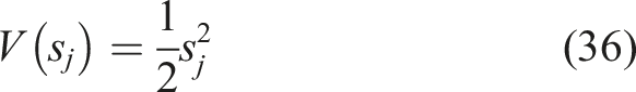
The derivative with respect to time can be expressed as: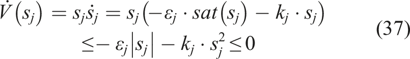
Since
4. Simulation verification
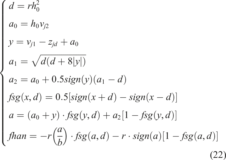
In this section, to validate the effectiveness of the proposed ADRSMC method, simulations are conducted under various road conditions. TD parameters are chosen as
4.1. Case 1: Bump road surface
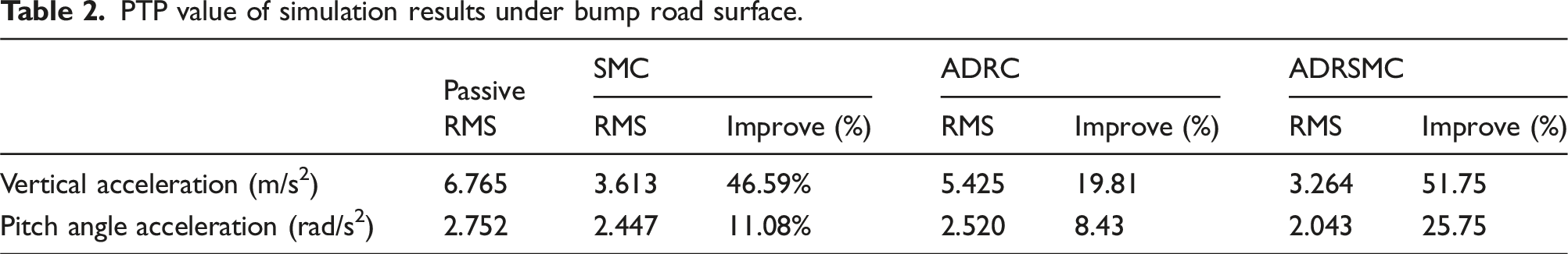
The bump road surface is a road condition characterized by significant undulations in the road surface occurring over a short period of time. It has big impacts on vehicle performance. The corresponding road displacement input is expressed as: Comparison of simulation results under bump road surface.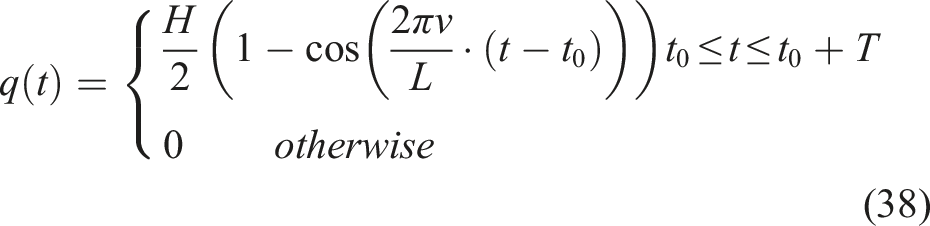
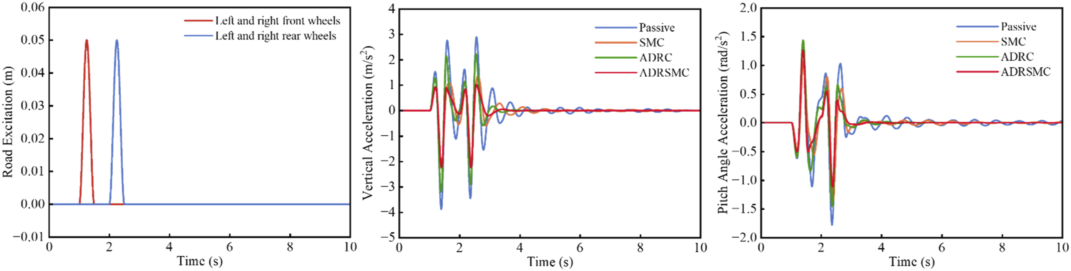
PTP value of simulation results under bump road surface.
4.2. Case 2: Random road surface
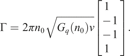
The single-wheel random road profile is modeled in the time domain using the filtered white noise method, described by the following equation:
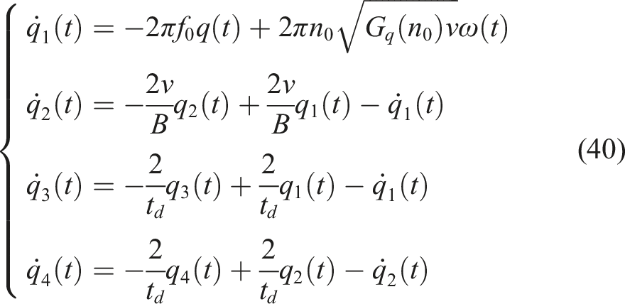

Rewrite equation (40) as follows:
The performance of Passive, ADRC, and ADRSMC are analyzed under the established random road excitation are shown in Figure 7. Comparison of simulation results under random road surface.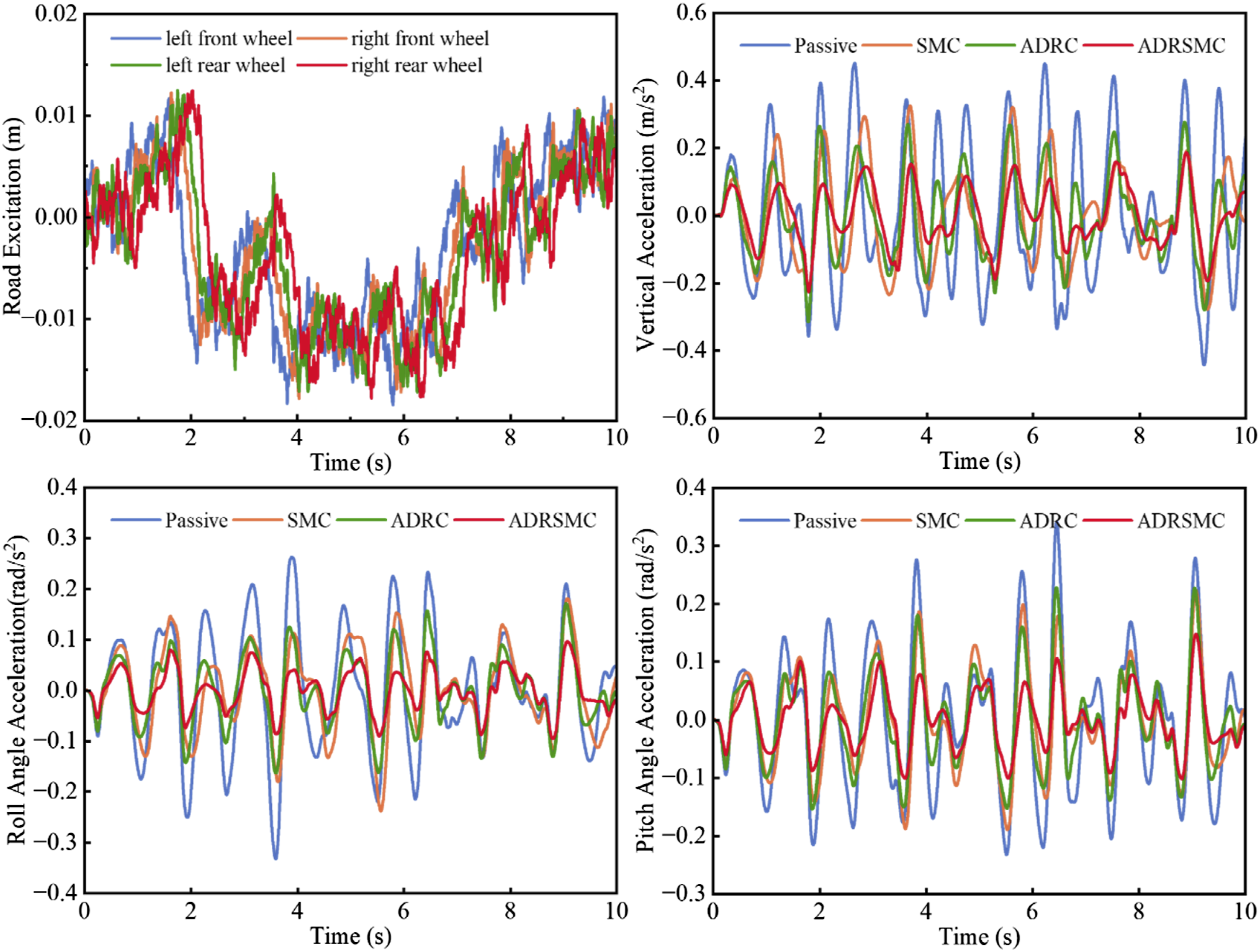
RMS value of simulation results under random road surface.
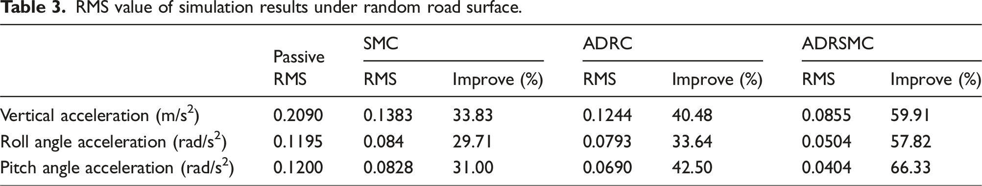
The power spectral density (PSD) of each performance indicators are shown in Figure 8. The proposed ADRSMC can significantly improve the dynamic performance of the body within the resonance frequency region compared to the SMC and ADRC, which verifies the improvement effect of the proposed controller on body vibration at a low-frequency range. PSD of dynamic performance indicators.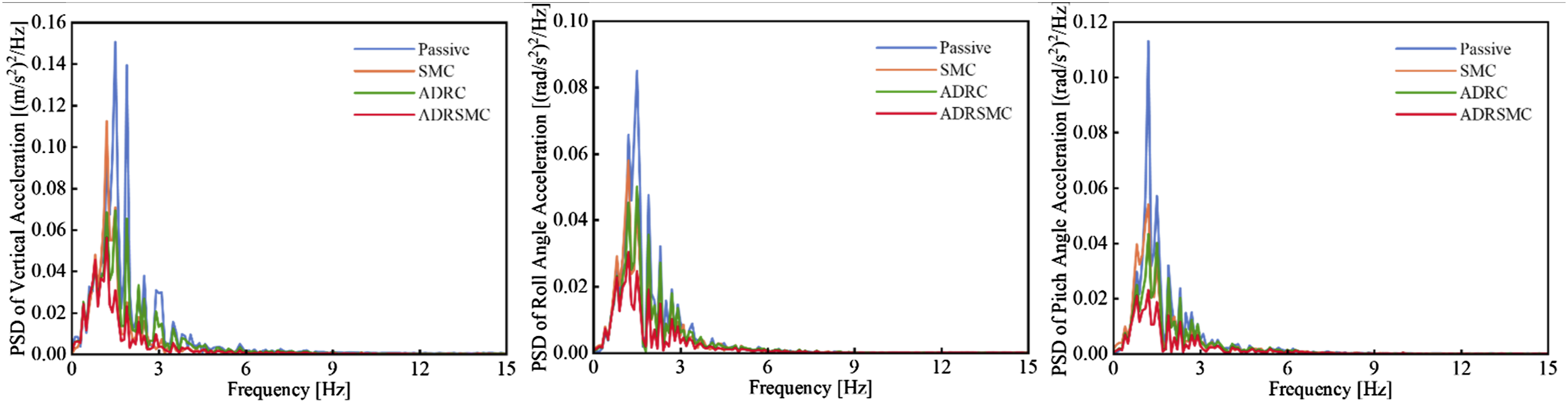
5. Experimental validation of the control algorithm
Due to experimental limitations, full vehicle active suspension verification was not possible. However, we selected the Quanser active suspension system to validate the effectiveness of the ADRSMC algorithm. The experimental setup is shown in Figure 9. Active suspension test system.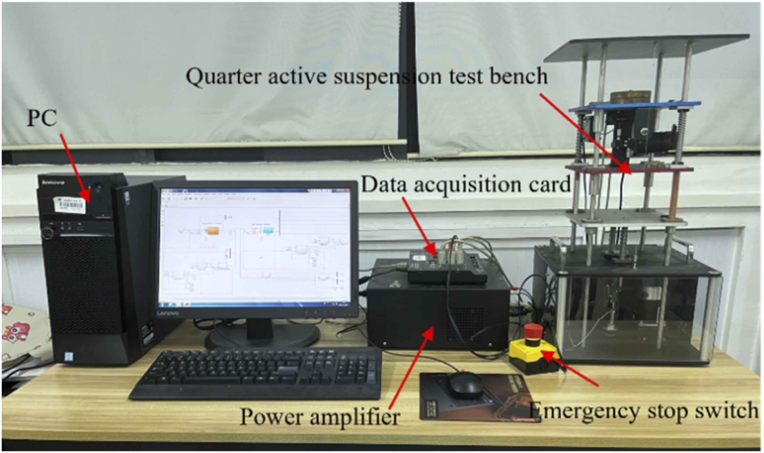
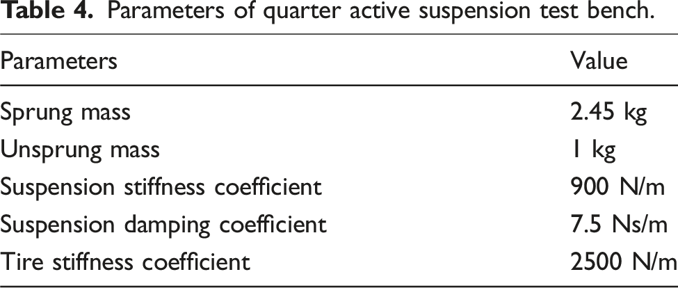
Parameters of quarter active suspension test bench.
5.1. Case 1: Bump road surface
The experimental results under the raised road surface as shown in Figure 10. The PTP values of each performance indicator are presented in Figure 11. Comparison of experimental results under bump road surface. PTP value of experimental results under bump road surface.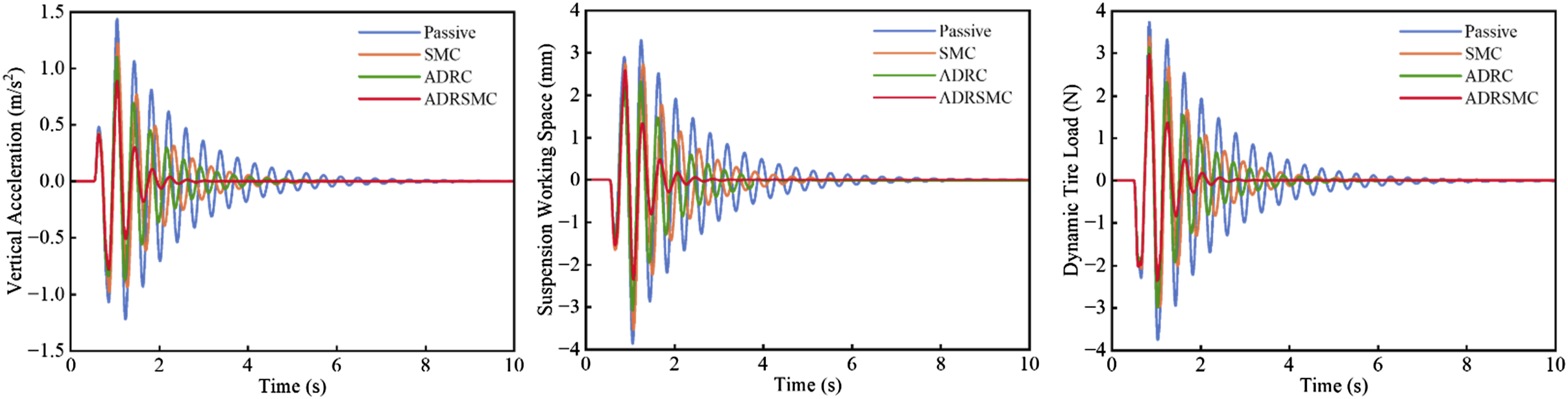
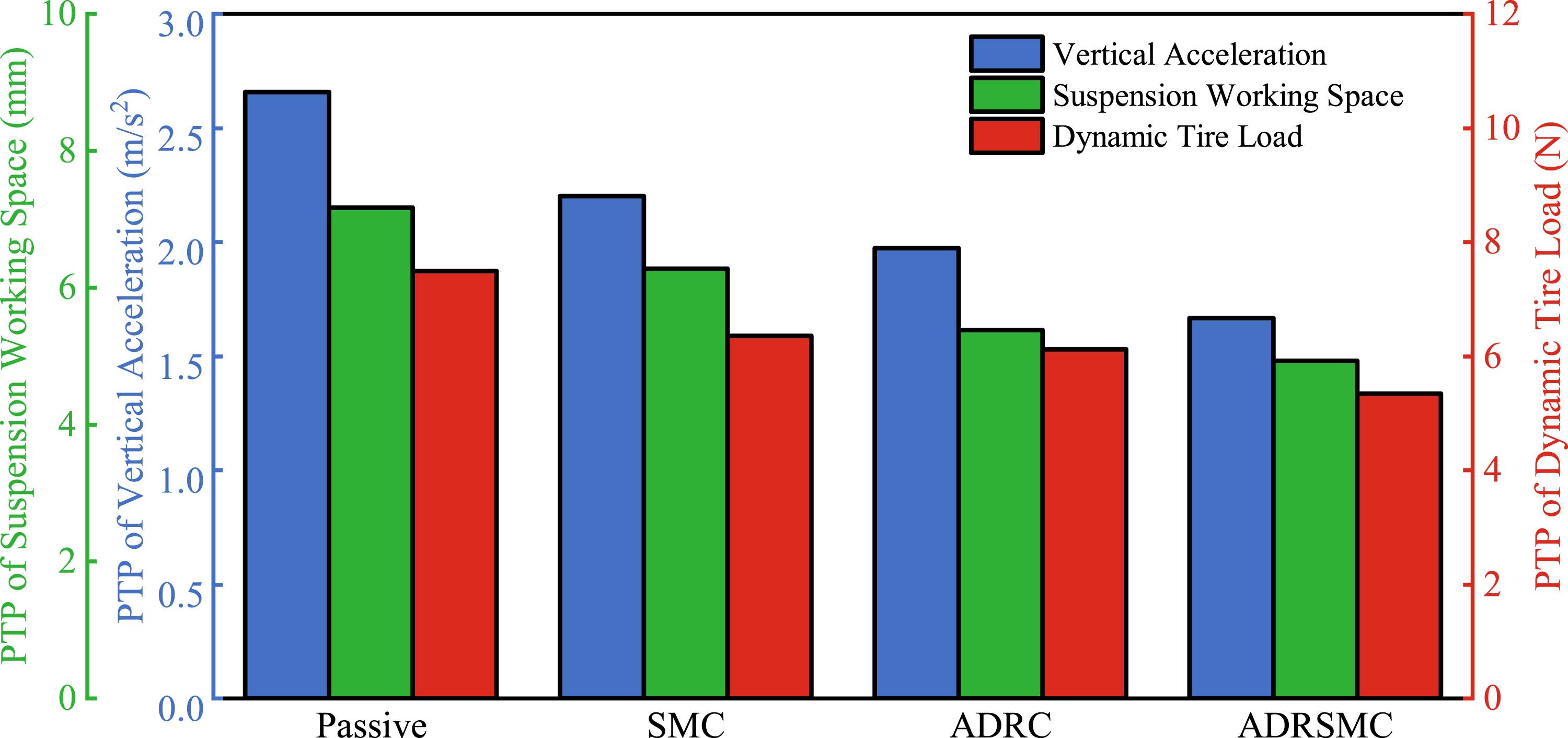
Figures 10 and 11 demonstrate that the proposed ADRSMC algorithm outperforms SMC and ADRC in both control effectiveness and convergence rate. Quantitative analysis reveals, compared to the passive suspension, the ADRSMC active suspensions reduce the sprung mass vertical acceleration by 37.22%. The suspension working space is reduced by 31.24%. And the dynamic tire load decreases by 28.71%. This significantly improves the ride comfort over bump road surface.
5.2. Case 2: Random road surface
The experimental results under the random road surface are shown in Figure 12, with the RMS values presented in Figure 13. Comparison of experimental results under random road surface. RMS value of experimental results under random road surface.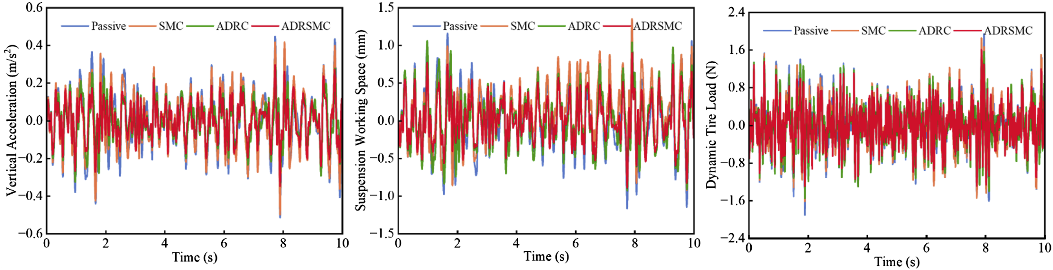
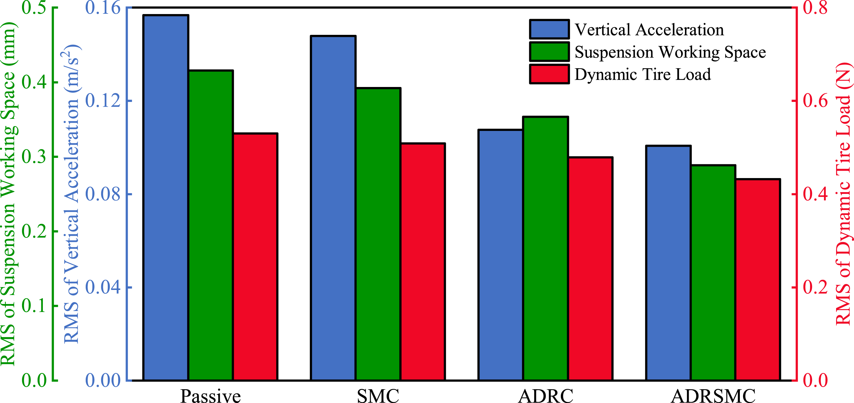
The experimental results demonstrate that under random road excitation, the active suspension system with ADRSMC reduces the sprung mass acceleration by 35.67% compared to the passive suspension, significantly improving ride comfort. Additionally, the suspension working space and dynamic tire load are decreased by 30.53% and 18.68% respectively, which is much better than those of SMC and ADRC, greatly improves the driving safety.
6. Conclusion
This paper proposes an innovative ADRSMC that combines ADRC with the SMC algorithm to address the nonlinearities and uncertainties in the hydro-pneumatic suspension system. The ADRSMC algorithm was designed to control the vertical, roll, and pitch motions of the vehicle body. The ESO estimates the lumped disturbances in the suspension system caused by model nonlinearities and unmodeled elements. The SMC law replaces the NLSEF in the ADRC to compensate for disturbances, enabling the control law to adapt to the control system state and achieve more effective control. In the end, simulation and experimental validations were conducted under the bump road and random road surfaces. The results showed that The ADRSMC algorithm significantly reduces the vibration generated by uneven road surfaces, enhances low-frequency vibration characteristics, and improves vehicle stability.
Footnotes
Declaration of conflicting interests
The author(s) declared no potential conflicts of interest with respect to the research, authorship, and/or publication of this article.
Funding
The author(s) disclosed receipt of the following financial support for the research, authorship, and/or publication of this article: This research was supported by the National Natural Science Foundation of China (Grant No. 52175084, 52202476) and the Central Guiding Local Science and Technology Development (Grant No. 236Z2204G).