
Abstract
The inerter-based vibration mitigation system can effectively enhance vibration mitigation performance by optimizing the topological configuration of components such as the inerter, spring, and damper. However, when the inerter-based vibration mitigation system is reversely connected, the change in energy transfer path can affect its effectiveness. This study takes the novel tuned mass damping inerter (NTMDI) as the research object, reverses its connection direction with the primary structure and the ground, and constructs a reversely connected configuration (NTMDI-R). Then, the theoretical model of a single-degree-of-freedom (SDOF) structure with NTMDI-R is presented, and the analytical solution for the optimal parameters of NTMDI-R is derived based on fixed-point theory. Finally, the effectiveness and robustness of NTMDI and NTMDI-R under harmonic and white noise excitation are analyzed and compared with Variant Tuned Mass Damper (VTMD) and Tuned Viscous Mass Damper (TVMD). The results show that the optimal parameters and control performance of NTMDI and NTMDI-R differ significantly. Under the same physical mass and apparent mass, NTMDI outperforms NTMDI-R in both vibration mitigation performance and control frequency range, with physical mass being the primary factor leading to the reduced performance of NTMDI-R. NTMDI and NTMDI-R exhibit consistent robustness, showing strong robustness under damping detuning and positive frequency detuning, but weaker robustness under negative frequency detuning. In contrast, VTMD demonstrates lower robustness under frequency detuning compared to NTMDI, NTMDI-R, and TVMD, indicating that apparent mass plays a significant role in enhancing robustness.
Introduction
The tuned mass damper (TMD) is an auxiliary mass system attached to the primary system to mitigate undesired vibrations. It has been widely utilized in the fields of civil engineering and mechanical engineering due to its simple design and high reliability (Elias and Matsagar, 2017; Lazar et al., 2016; Liu et al., 2020, 2021; Love et al., 2023). Frahm (1911) first introduced the concept of TMD by using a spring element to connect the auxiliary mass to the primary system. However, this auxiliary mass system is effective only within a narrow frequency band. To address this limitation, Den Hartog (1985) pioneeringly introduced a damping element into the auxiliary mass system. The parallel spring-damping design significantly broadened the effective operating frequency range of the system. Furthermore, Den Hartog (1985) found two frequency points (i.e., fixed points) that are independent of the TMD damping in the frequency-response curve of an SDOF structure with a TMD. Based on these findings, Den Hartog proposed the fixed-point theory for the optimal design of the TMD. Since then, this method has been widely applied in the optimization design of TMD (Hu et al., 2015; Kaveh et al., 2020; Liu and Liu, 2005; Nishihara and Asami, 2002). Ren (2001) connected the damping element of the TMD directly to the ground and proposed a Variant Tuned Mass Damper (VTMD). The results indicated that the frequency-response curve of the primary structure with the VTMD still satisfied the fixed-point theory, which was used to derive the optimal design of the VTMD.
To achieve the desired control performance, traditional TMD generally requires a considerable physical mass. However, such a large mass is not only limited by engineering costs and available installation space, but it may also impose additional dynamic loads on the primary structure. The discovery of inerter technology offers an effective solution to this challenge (Shen et al., 2023; Wang et al., 2014). The inerter, proposed by Smith (2002), is a two-terminal control element whose reaction force is proportional to the relative acceleration between its two ends. This proportionality constant is defined as the apparent mass. The apparent mass of the inerter significantly exceeds its physical mass, and this mass amplification effect provides an effective solution for the lightweight design of vibration suppression systems. Inerters can be implemented through mechanisms such as gear racks (Siami and Karimi, 2020; Sun et al., 2016), ball screws (Pietrosanti et al., 2020; Sadeghian et al., 2021), hydraulics (Liu et al., 2019; Wagg and Pei, 2020), and fluidic devices (Liu et al., 2018; Ma et al., 2021).
As a novel component with energy transfer characteristics, the inerter alone struggles to fully exert its vibration mitigation effectiveness. By coupling the inerter with energy dissipation devices to construct a composite vibration reduction system, the effectiveness of structural vibration control can be significantly enhanced. Based on this principle, various inerter-based vibration control systems have been proposed and implemented in engineering practices. Saito and Inoue (2007) introduced the inerter into rotational viscous dampers and proposed the first inerter-based vibration control system, known as the Tuned Viscous Mass Damper (TVMD). Garrido et al. (2013) proposed the rotational inertia double tuned mass damper (RIDTMD) by replacing the damping element in the TMD with TVMD and optimized its parameters using H∞ methods. Javidialesaadi and Wierschem (2018) conducted a comparative study on the seismic effectiveness of the RIDTMD and TMD. The results indicated that the RIDTMD was superior to the TMD in terms of seismic resistance. Lazar et al. (2014, 2016) proposed the tuned inerter damper (TID) by replacing the mass block in TMD with an inerter. Sun et al. (2017) have investigated the application of TID in vibration control and proposed an approximate parameter design method. Zhang et al. (2016) systematically explored inerter-based topological configurations and demonstrated that TID implementation could simultaneously achieve cost reduction and damper size minimization. Zhang et al. (2022) implemented TID between the tower and girder of a cable-stayed bridge to mitigate girder displacement, and its performance was compared with that of traditional viscous dampers (VD). The results demonstrated that TID was more effective in mitigating girder displacement.
Marian and Giaralis (2014) proposed the tuned mass damper inerter (TMDI) by connecting the physical mass of the TMD to the ground using an inerter. Subsequently, Marian and Giaralis (2017) used the TMDI to suppress harmonic vibrations in SDOF structures, and the results indicated that the TMDI was superior to the traditional TMD in vibration reduction. Pietrosanti et al. (2017) evaluated the effectiveness of the TMDI and found that it exceeds traditional TMD in both vibration reduction and robustness. Giaralis and Petrini (2017) and Zhang and Fitzgerald (2020) investigated the effectiveness of the TMDI for wind turbine blades and high-rise buildings, respectively. Building upon the concept of TMDI, Li et al. (2023) proposed a novel tuned mass damper inerter (NTMDI) by repositioning the damping element and connecting it in parallel with the inerter. The results demonstrated that the NTMDI exhibits superior vibration mitigation performance and enhanced robustness compared to TMDI. To the best of the authors’ knowledge, NTMDI is the most theoretically effective inerter-based vibration control system to date.
The aforementioned inerter-based vibration control systems optimize their mechanical performance by adjusting the positions of inerter, spring, and damper. However, the impact mechanism of connection orientation on their performance remains unclear. Therefore, this paper focuses on the NTMDI and its reverse connection configuration (NTMDI-R). Firstly, a single-degree-of-freedom structural mechanical model incorporating NTMDI-R is established, and an analytical solution for the optimal parameters of NTMDI-R is derived based on the fixed-point theory. Subsequently, under harmonic excitation and white noise excitation, a comparative analysis is conducted to examine the differences in vibration mitigation performance and robustness among NTMDI, NTMDI-R, TVMD, and VTMD. Finally, a systematic summary of the research findings is presented.
Theoretical model
Figure 1 illustrates the theoretical models of an SDOF primary structure equipped with four different control systems (NTMDI, NTMDI-R, VTMD, and TVMD). The parameters of the coupled system are defined as follows: the mass (m
s
) and stiffness (k
s
) of the primary structure, and the mass (m
d
), stiffness (k
d
), damping coefficient (c
d
), and inertial mass (m
i
) of the control system. Among them, m
s
and m
d
have only horizontal degrees of freedom, and their horizontal displacements relative to the ground are represented x
s
and x
d
, respectively. It is noteworthy that when m
i
= 0, the NTMDI reduces to the VTMD, and when m
d
= 0, the NTMDI-R simplifies to the TVMD. Consequently, the proposed model exhibits parametric generality. The theoretical models of an SDOF primary structure with different control systems under base acceleration: (a) NTMDI (Li et al., 2023), (b) NTMDI-R, (c) VTMD (Ren, 2001), (d) TVMD (Ikago et al., 2012).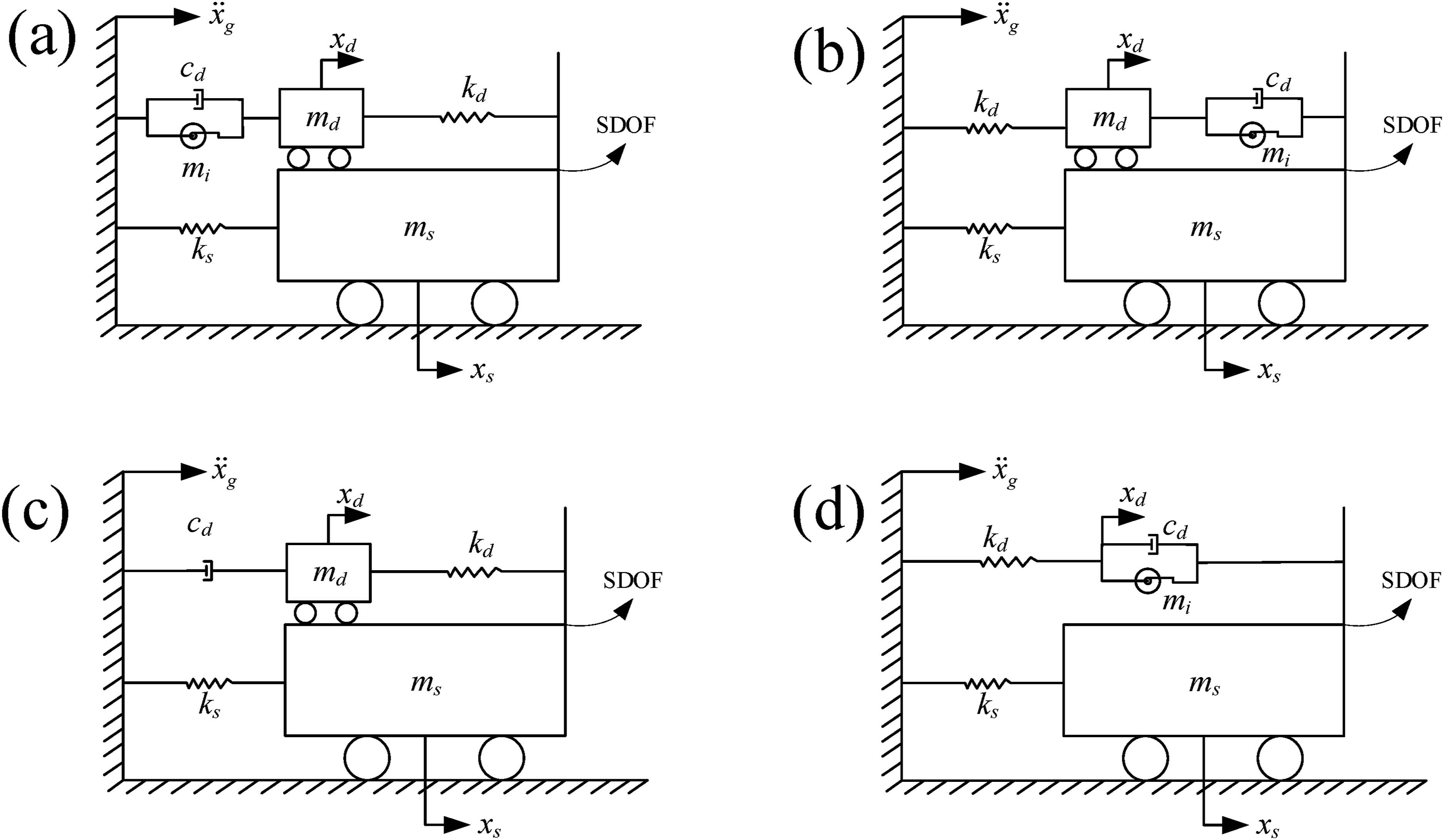
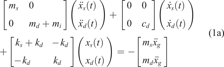
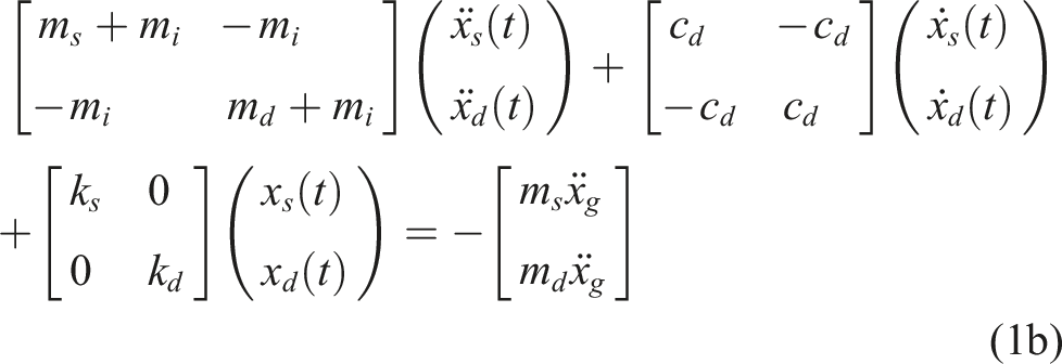
Based on D'Alembert’s principle, under base acceleration excitation (ẍ
g
), the equations of motion for the primary structure equipped with NTMDI and NTMDI-R are presented in Equations (1a) and (1b), respectively. Equation (1) indicates that the differences in their dynamic characteristics are the primary reason for the differences in vibration mitigation performance. Since the analysis of NTMDI has been thoroughly discussed in Li et al. (2023), this study focuses on a detailed derivation of the equations of motion for NTMDI-R.
Assuming the base acceleration is a harmonic load and introducing the following dimensionless parameters.
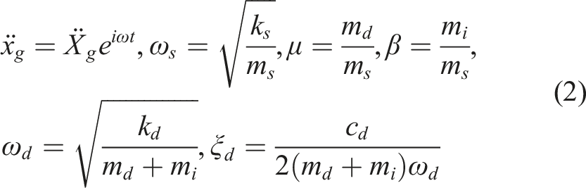
Substituting equation (2) into equation (1b).
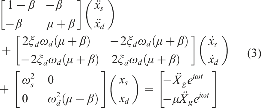
The solution of equation (3) can be assumed as:

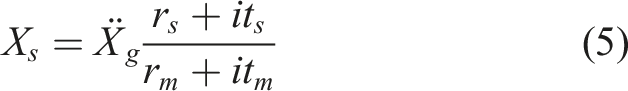
Substituting equation (4) into equation (3), X
s
can be calculated as:
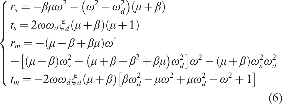
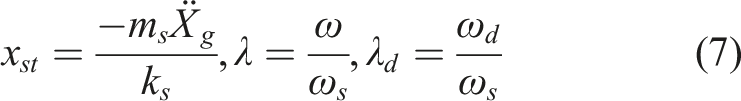
Introducing the following dimensionless parameters in equation (7):
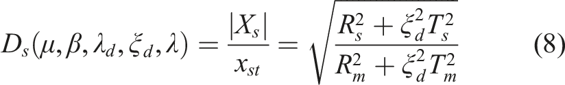
The dynamic magnification factor D
s
of the primary structure can be derived as follows:
Optimal design of NTMDI-R
Fixed point theory
The dynamic magnification factor of the primary structure with NTMDI-R (Equation (8)) is a function of the parameters μ, β, λ, λ
d
, and ξ
d
. Among these, μ, β, and λ are known parameters determined by the structural characteristics and vibration reduction objectives, while λ
d
and ξ
d
are unknown parameters to be optimized. Figure 2 shows the frequency response curves of the primary structure equipped with NTMDI and NTMDI-R under the conditions μ = 0.01, β = 0.1, and λ
d
= 1.0. The results indicate that the frequency response curves for both devices pass through two fixed points (P and Q) that are independent of damping. This implies that the optimal parameters of NTMDI and NTMDI-R can be determined using the fixed-point theory (Den Hartog 1985). The fixed-point theory, proposed by Den Hartog, is an optimal design method aimed at minimizing the maximum response of the primary structure. Frequency response curve of the primary structure with the control system: (a) NTMDI, (b) NTMDI-R.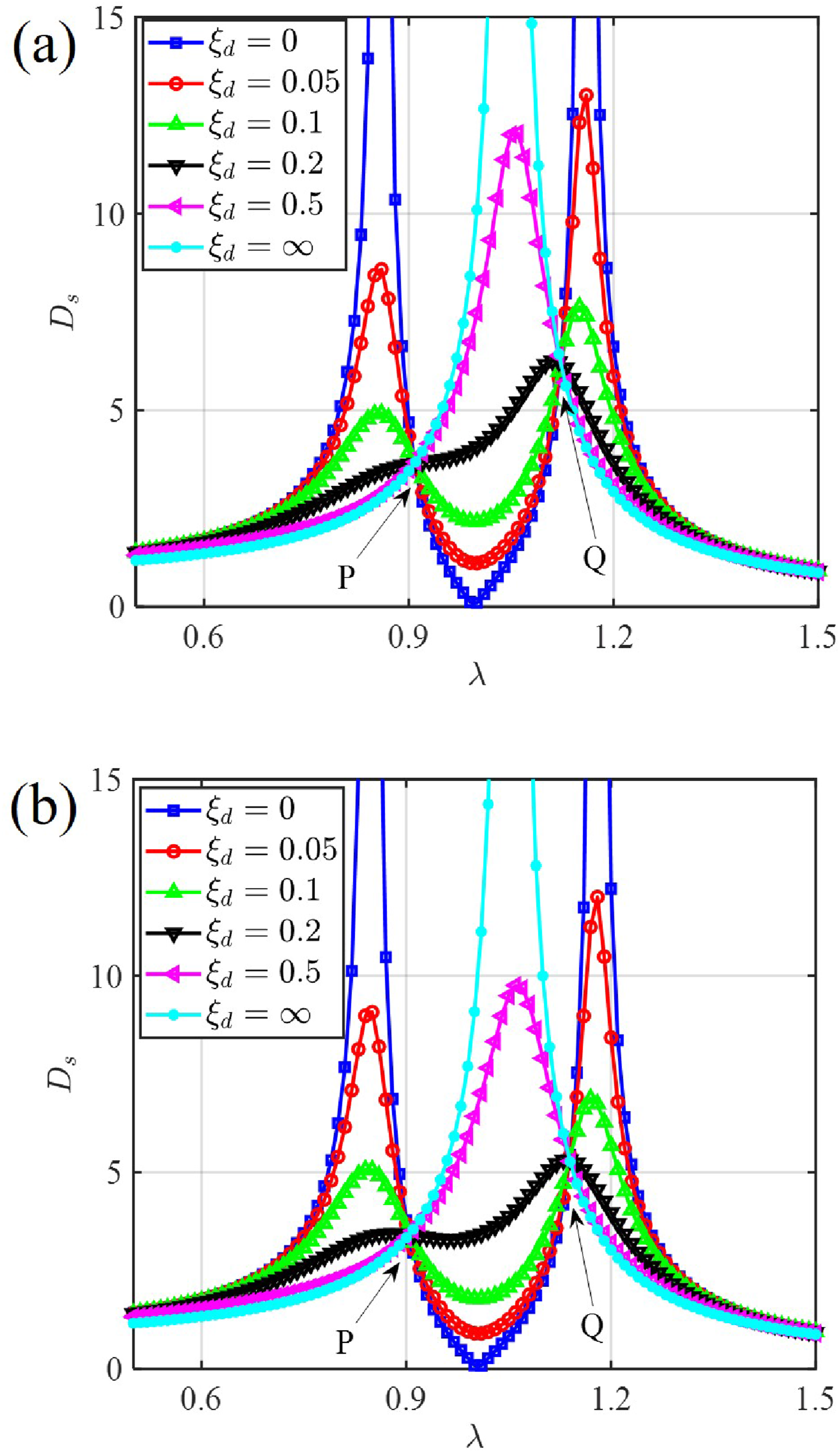
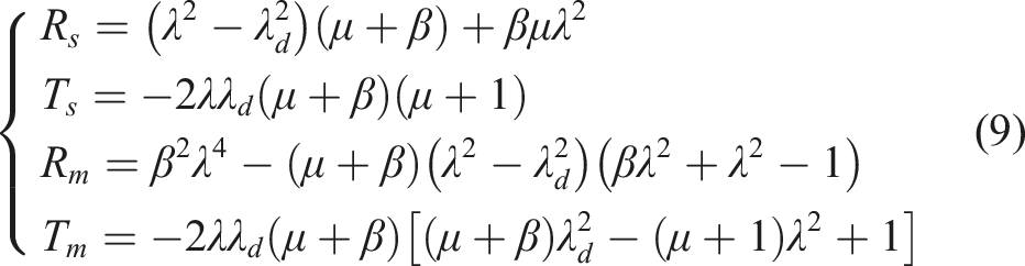
According to Den Hartog’s fixed-point theory, the frequency response curve of the primary structure with NTMDI-R exhibits two fixed-frequency points, at which the amplitude remains unchanged regardless of damping. Consequently, when ξ
d
= 0 and ξ
d
= ∞, the amplitudes at these two fixed points satisfy equation (10).
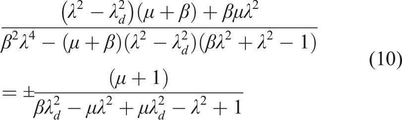
The following formula can be obtained from Vieta’s theorem:
When ξ
d
= ∞, equation (8) can be simplified as follows:
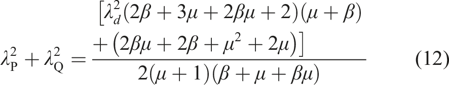
According to the fixed-point theory, it is known that the response values at the two points λP and λQ are equal under the optimal frequency ratio, and the following relationship can be obtained:
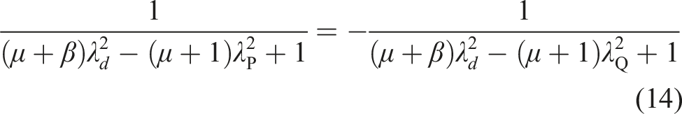
Equation (14) can be simplified as follows:
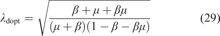
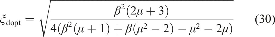
Based on Equations (12) and (15), the formula for the optimized tuning frequency ratio λdopt can be obtained.
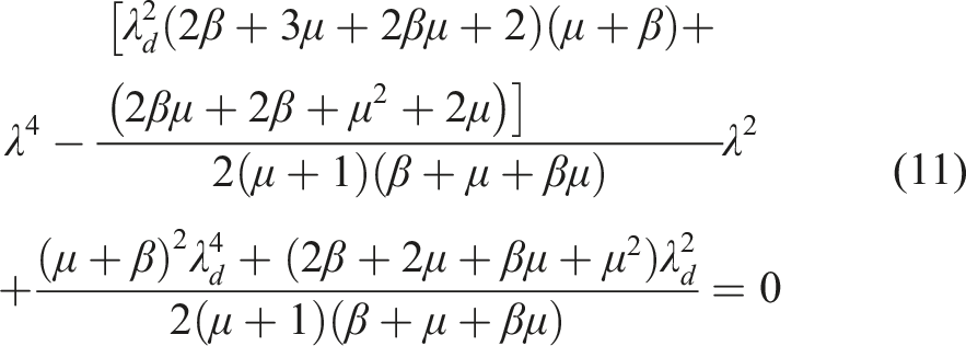
Substituting equation (16) into equation (11), the abscissae of the two fixed points can be obtained as:
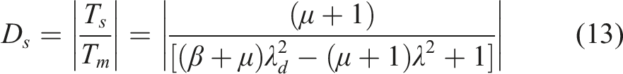
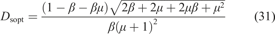
Substituting equations (16) and (17) into equation (13), the optimum dynamic magnification factor can be derived,
To achieve the greatest vibration reduction effect, the dynamic magnification factors at points P and Q should be minimized. Therefore, equation (8) must satisfy the extremum conditions:
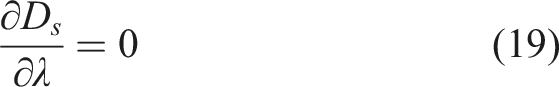
Since D
s
and λ are both greater than zero, the following can be obtained:
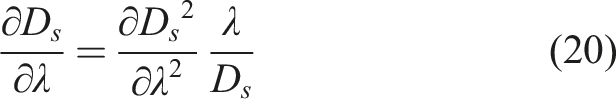
Let equation (8) be simplified as:
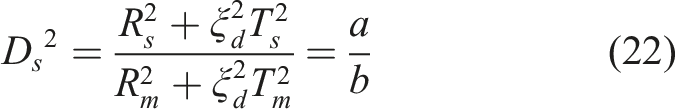
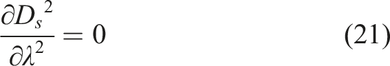
Substituting equation (22) into equation (21).
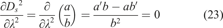
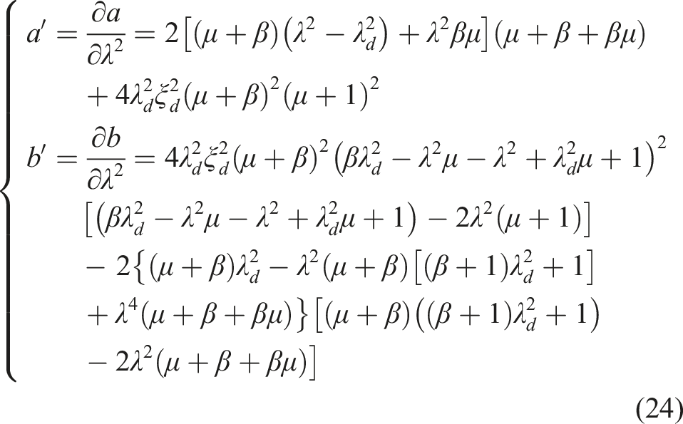
Equation (23) can be simplified as:

Under the condition of the optimal frequency ratio λdopt, Points P and Q satisfy:
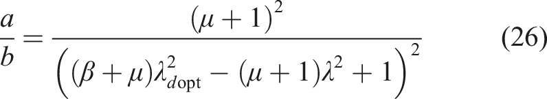
Combine equations (25) and (26).

The square values of the damping ratios at the two fixed points can be obtained by combining equations (16), (17), and (27). It should be noted that it is impossible to make the dynamic magnification factor of the primary structure at both Points P and Q to obtain the maximum value at the same time. Therefore, the optimal damping ratio ξdopt is determined by averaging the damping ratios at the two fixed points, thereby balancing the control effectiveness at both points.

Under harmonic force excitation, the frequency response curve of the primary structure with NTMDI-R still follows the fixed-point theory. Through a similar derivation, the optimal frequency ratio, damping ratio, and dynamic magnification factor of NTMDI-R can be obtained. It should be emphasized that for multi-degree-of-freedom systems with well-separated modes, the optimization results based on the single-degree-of-freedom model remain valuable; however, in systems with closely spaced modes and significant modal coupling, the single-degree-of-freedom equivalence assumption is invalid, and the corresponding optimization results are not directly applicable.
Comparison of optimization parameters
Figure 3 presents a comparison of the optimal parameters for NTMDI-R and NTMDI under base acceleration excitation. These parameters include optimal frequency ratio, damping ratio, and dynamic magnification factor of the primary structure. As shown in Figure 3(a), the optimal frequency ratios of both systems exhibit a monotonic increasing trend with μ and β. When μ = 0.01, the two systems are highly consistent. In the range of β ∈ [0, 0.1], the relative magnitude of the frequency ratio still depends on the effect of μ. However, when β > 0.1, the frequency ratio of NTMDI-R is always greater than that of NTMDI. Comparison of optimal parameters for NTMDI-R and NTMDI under harmonic base acceleration excitation: (a) λdopt, (b) ξdopt, (c) Dsopt.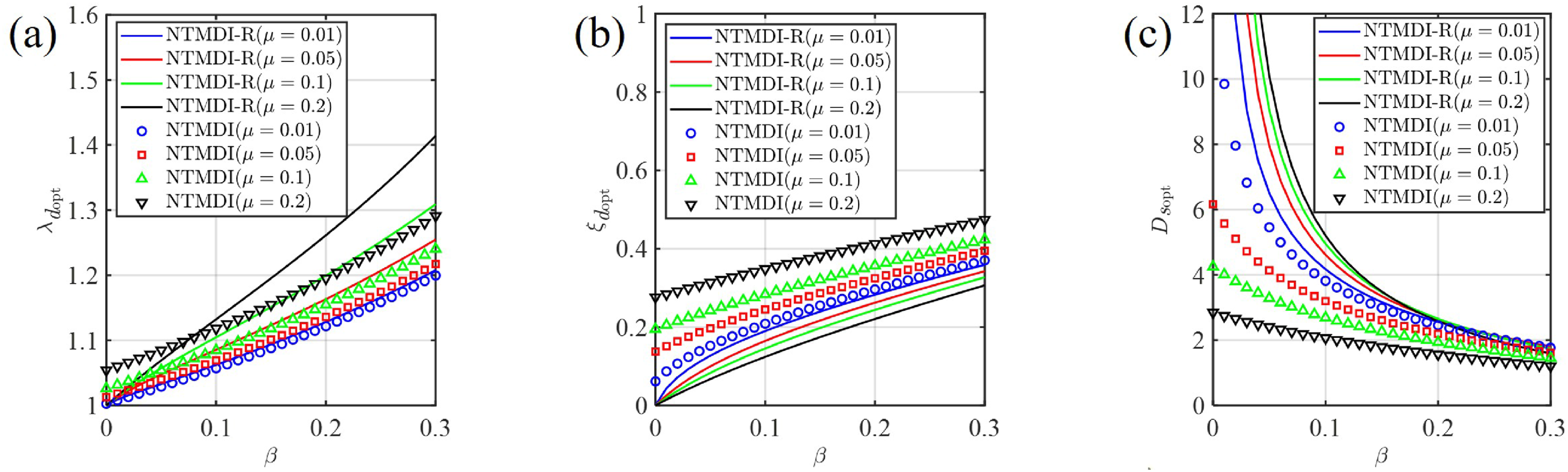
Figure 3(b) shows that as β increases, the optimal damping ratios for both NTMDI-R and NTMDI gradually increase. However, as μ increases, the optimal damping ratio of NTMDI-R gradually decreases, while that of NTMDI continues to rise. Under constant β, an increase in μ leads to a greater divergence in damping ratios between the two systems; conversely, under constant μ, the divergence in optimal damping ratios between the two systems gradually decreases as β increases.
Figure 3(c) indicates that as β increases, the optimal dynamic magnification factors of the primary structure with NTMDI-R and NTMDI both decrease, indicating that a larger β enhances the effectiveness of these two devices. However, the impact of μ on the two devices differs. For NTMDI, its performance consistently improves with increasing μ. Whereas the performance of NTMDI-R is more dependent on β. When β is less than 0.2, the effectiveness of NTMDI-R decreases as μ increases; when β is greater than 0.2, it improves with increasing μ, but remains lower than that of NTMDI.
Figure 4 presents a comparison of the optimal parameters for NTMDI-R and NTMDI under harmonic force excitation. The result shows that the optimal frequency ratio of NTMDI is generally higher than that of NTMDI-R, which is the opposite of the results under base acceleration excitation. However, the trends in the optimal damping ratio of NTMDI and NTMDI-R, as well as the dynamic magnification factor of the primary structure, are largely consistent with those observed in Figure 3. Comparison of optimal parameters for NTMDI-R and NTMDI under harmonic force excitation. (a) λdopt, (b) ξdopt, (c) Dsopt.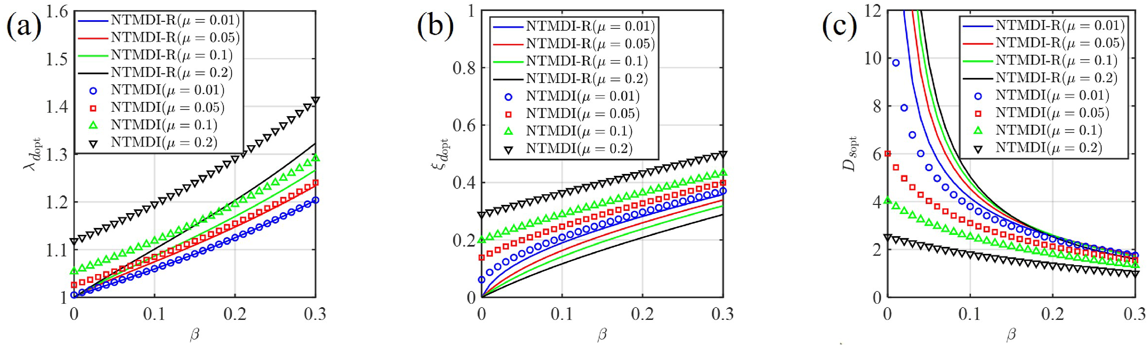
Comparative analysis of effectiveness
Harmonic excitation
Figure 5 presents the optimal dynamic magnification factors of the primary structure for four control systems (NTMDI-R, TVMD, NTMDI, and VTMD) under base acceleration excitation. Notably, the NTMDI-R system reduces to TVMD when μ = 0, while the NTMDI system degenerates into VTMD when β = 0. For the NTMDI-R and TVMD systems (Figure 5(a)), Dsopt exhibits a continuous decrease as increasing β. However, the influence of μ diverges significantly across β ranges: increasing μ weakens vibration suppression when β < 0.2, but enhances system performance when β > 0.2. This reveals a critical parameter threshold (β ≈ 0.2) for NTMDI-R, indicating that configurations with lower μ are preferable below this threshold, whereas higher μ values are required above it to optimize control effectiveness. Comparing NTMDI and VTMD systems (Figure 5(b)), it can be observed that the Dsopt of NTMDI and VTMD continuously decreases with increasing μ and β, indicating that higher μ and β contribute to improved vibration suppression, with a more pronounced effect at smaller β values. For example, when β = 0.01, increasing μ from 0.05 to 0.1 leads to a 28% reduction in Dsopt. However, when β = 0.1, the same change in μ leads to only a 15.9% reduction in Dsopt. Comparison of dynamic magnification factors under harmonic base acceleration excitation: (a) NTMDI-R and TVMD, (b) NTMDI and VTMD.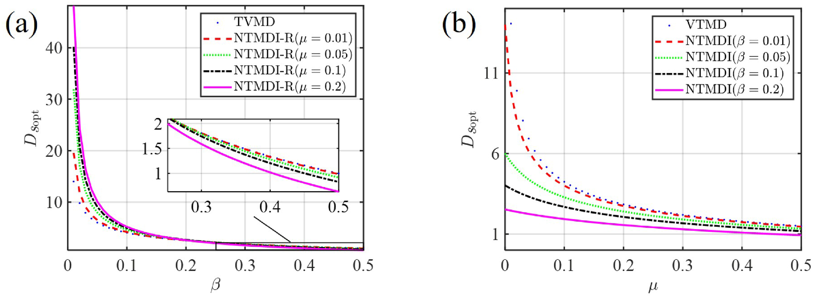
Figure 6 illustrates the optimal dynamic magnification factors of the primary structure for four control systems under harmonic force excitation. Comparing Figure 6 with Figure 5, it is evident that the variation trends of these factors are consistent with those observed under base acceleration. Therefore, a detailed discussion is omitted. It is noteworthy that the optimal parameters for NTMDI and NTMDI-R show similar trends under force excitation and base acceleration excitation. Thus, subsequent studies will be conducted based on base acceleration excitation. Comparison of dynamic magnification factors under harmonic force excitation: (a) NTMDI-R and TVMD, (b) NTMDI and VTMD.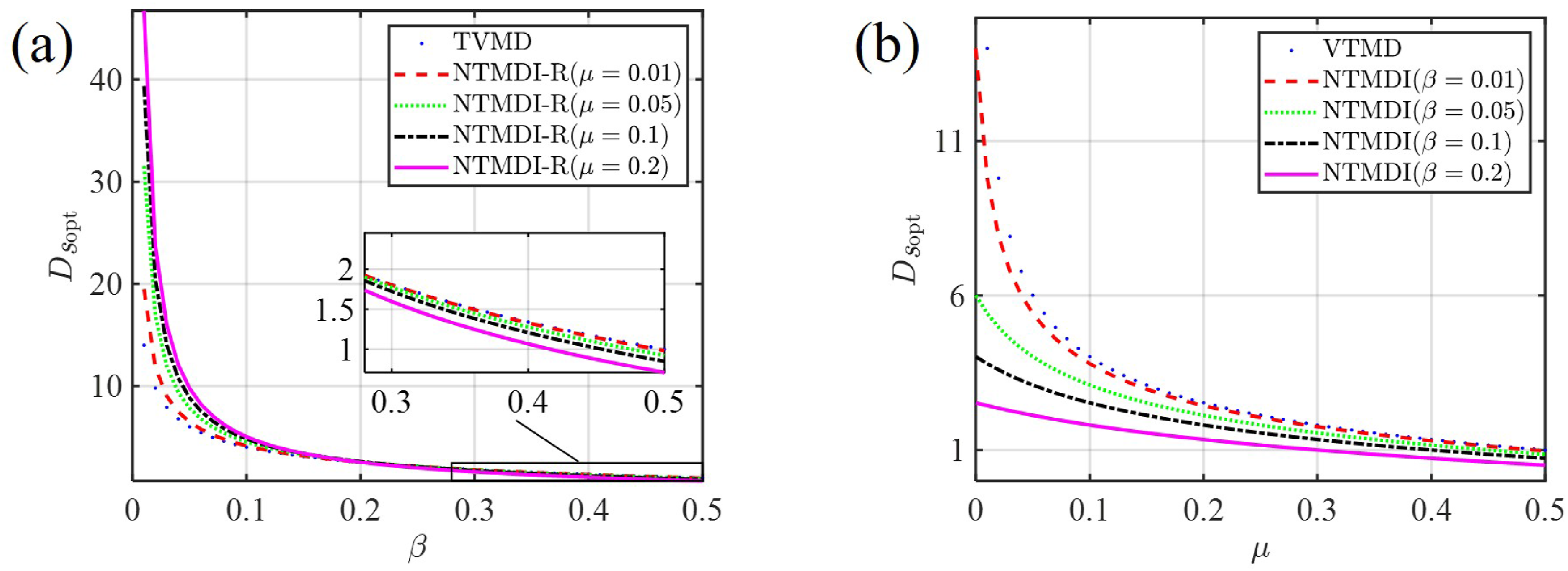
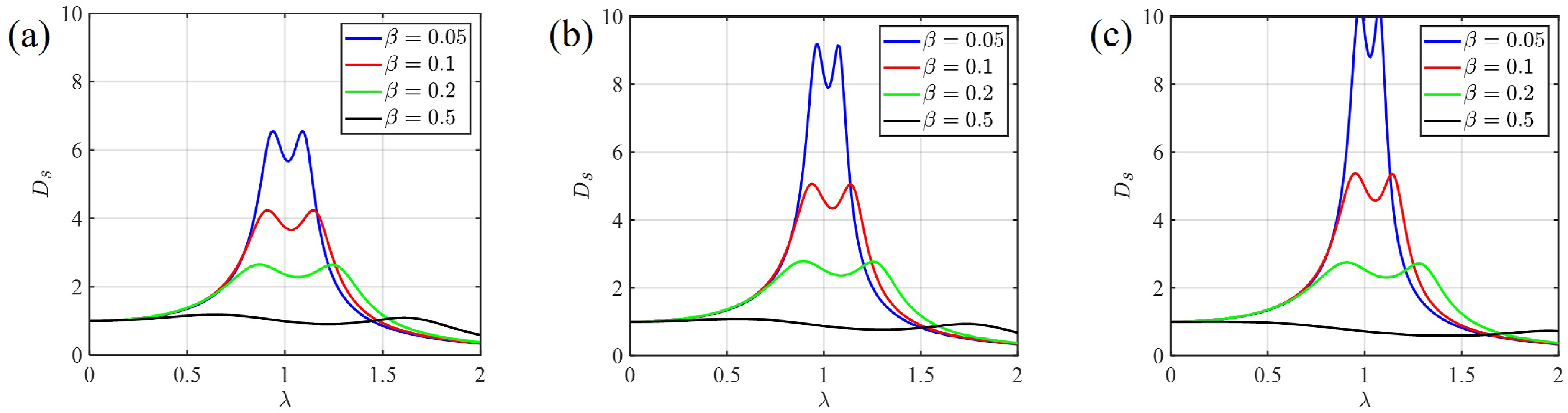
Figures 7 and 8 compare the effectiveness of the NTMDI and NTMDI-R systems. For the NTMDI system, increasing μ and β can effectively reduce the peak response of the primary structure and significantly broaden the vibration control bandwidth. However, For the NTMDI-R system, increasing β reduces peak response and broadens the bandwidth, but this beneficial effect weakens as μ increases, even showing an opposite trend. In contrast, under identical parametric configurations, the NTMDI system outperforms the NTMDI-R system in both peak response suppression and control bandwidth expansion. Frequency response curve of the primary structure with NTMDI under harmonic base acceleration excitation: (a) µ = 0.01, (b) µ = 0.1, (c) µ = 0.2. Frequency response curve of the primary structure with NTMDI-R under harmonic base acceleration excitation: (a) µ = 0.01, (b) µ = 0.1, (c) µ = 0.2.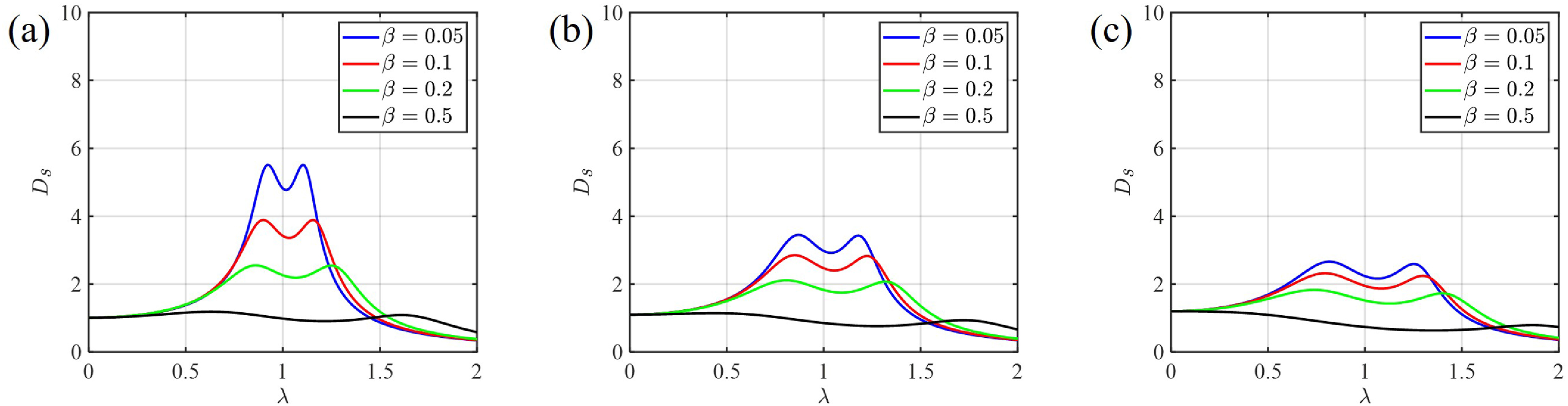
White noise excitation
In practical engineering, structures are often subjected to stochastic loads, including wind loads and seismic excitations. Therefore, it is crucial to systematically evaluate the vibration mitigation effectiveness of NTMDI and NTMDI-R under stochastic load excitation.
Utilizing the state-space methodology (Pietrosanti et al., 2017), equation (3) can be represented as follows:

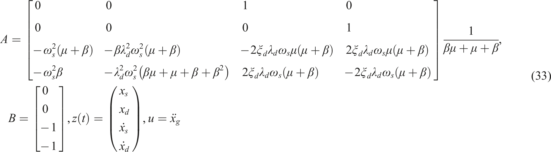
Assuming the input load is a stationary white noise excitation, the steady-state covariance matrix of the state vector z(t) can be expressed as:

The steady-state covariance matrix G
zz
(t) in equation (34) satisfies the Lyapunov Equation:

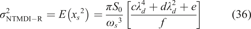
By solving equation (35), the steady-state covariance matrix can be obtained, and thus the response mean square value of the primary structure with NTMDI-R can be derived as:
Similarly, by adjusting the state matrix A and input matrix B in equation (32), the mean square response of the primary structure equipped with the aforementioned three control systems (i.e., VTMD, TVMD, and NTMDI) can be derived individually. The formulas for the mean square response of the primary structure with these three control systems can be found in Li et al. (2023) and are not reiterated here.
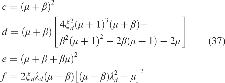
By substituting Equations (16) and (28) into equation (36), the optimal mean square response of the primary structure with NTMDI-R can be obtained. Figure 9 illustrates the optimal mean square response of the primary structure under white noise excitation. The results indicate that the trend in performance of the four control systems is consistent with that observed under harmonic excitation (see Figures 3(c) and 5). For small values of β, the vibration mitigation performance of NTMDI-R is inferior to that of NTMDI and TVMD. However, for large values of β, NTMDI-R outperforms both NTMDI and TVMD. In addition, NTMDI consistently demonstrates superior performance compared to VTMD. Comparison of RMS responses of the primary structure under white noise excitation: (a) NTMDI and NTMDI-R, (b) NTMDI-R and TVMD, (c) NTMDI and VTMD.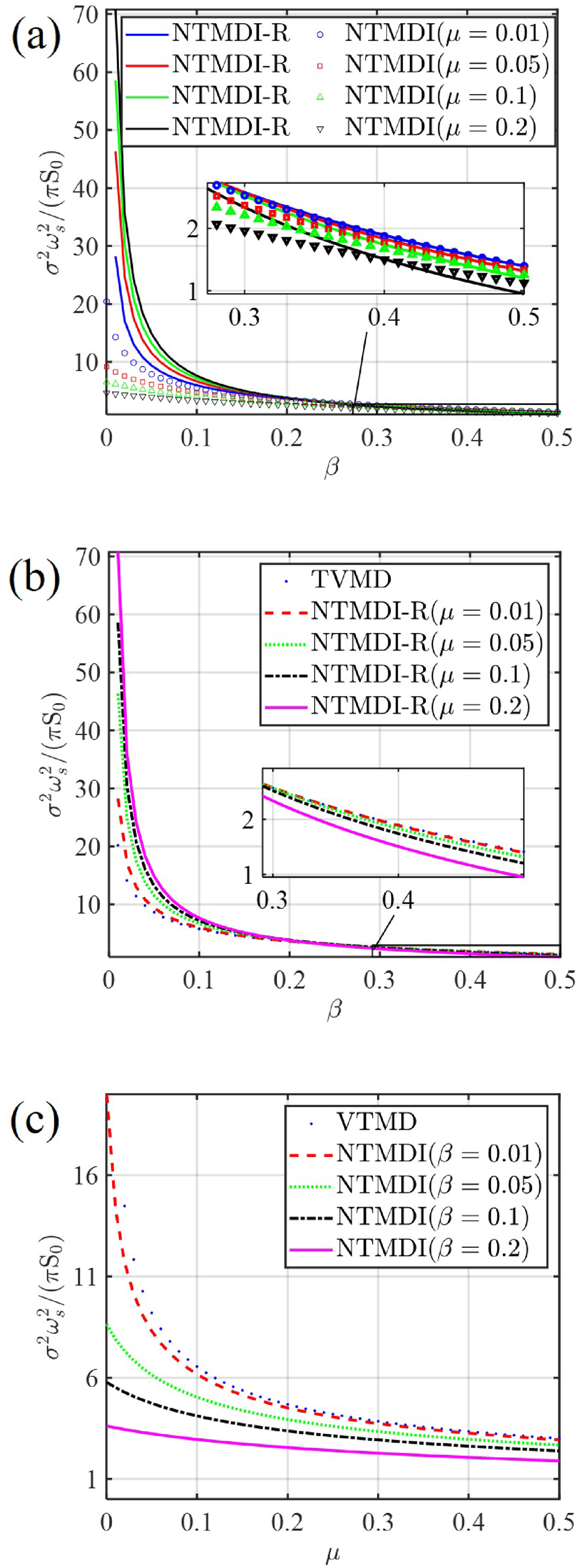
Comparative analysis of robustness
During the service life of vibration control systems, uncertainties in the environment often cause deviations in operational frequency and damping from the design values, which can significantly reduce their control effectiveness. Therefore, a comprehensive analysis of the robustness of NTMDI and NTMDI-R is necessary.
The frequency detuning ratio γ
λ
and the damping detuning ratio γ
ξ
are used to quantify the deviations in frequency and damping, respectively, as defined in equation (38).
Harmonic excitation
Detuning in optimal frequency ratio
Figure 10 presents the frequency response curves of the primary structure for the four control systems under optimal frequency ratio detuning. The positive, zero, and negative values of γ
λ
correspond to positive, zero, and negative frequency ratio detuning, respectively. All results are obtained with µ = 0.01 and β = 0.1. The values in Figure 10 represent the peak values of the frequency response curves, which applies to subsequent figures as well. Frequency-response curve of the primary structure under optimal frequency ratio detuning: (a) γλ = 0, (b) γλ = −5%, (c) γλ = −10%, (d) γλ = −20%, (e) γλ = 5%, (f) γλ = 10%, (g) γλ = 20%.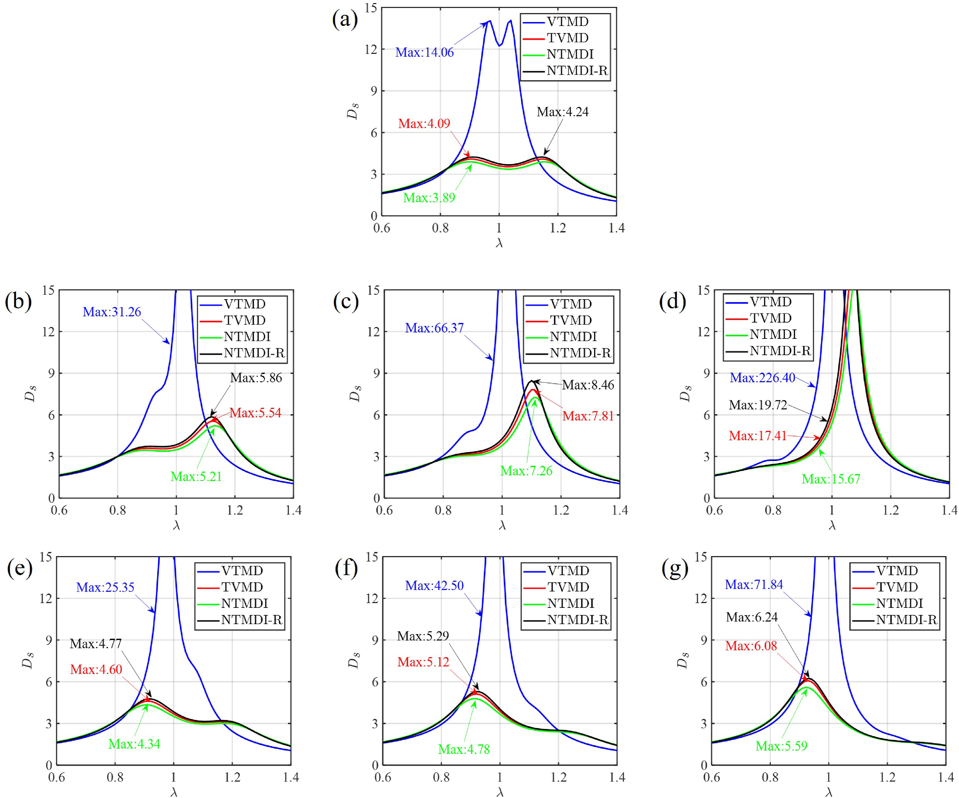
Figure 10 shows that the effect of optimal frequency ratio detuning on the dynamic magnification factor of the primary structure is significantly smaller for TVMD, NTMDI, and NTMDI-R compared to VTMD, suggesting that the apparent mass enhances robustness. Under positive detuning, TVMD, NTMDI, and NTMDI-R exhibit better robustness compared to negative detuning. For example, when γ λ = −10%, the maximum response values for TVMD, NTMDI, and NTMDI-R are 7.81, 7.26, and 8.46, respectively. However, when γ λ = 10%, these values are 5.12, 4.78, and 5.29. During negative detuning, the peak responses of all four control systems shift to the right, whereas under positive detuning, they shift to the left. Additionally, NTMDI and NTMDI-R exhibit consistent performance, indicating that the connection orientation does not significantly impact the robustness of the control system under frequency ratio detuning.
To investigate the effects of mass ratios (μ and β) on the effectiveness of NTMDI and NTMDI-R under optimal frequency ratio detuning condition, Figure 11 presents the frequency response curves of the primary structure at γ
λ
= ±10%. Figure 11(a) and (b) indicate that NTMDI-R exhibits better robustness under positive frequency detuning, while its control performance deteriorates with increasing μ under both positive and negative frequency detuning. Figure 11(c) and (d) indicate that NTMDI also demonstrates superior robustness under positive frequency detuning, and its control performance improves significantly with increasing β under both positive and negative frequency detuning. Frequency response curves of the primary structure under optimal frequency ratio detuning: (a) γλ = −10%, β = 0.1, (NTMDI-R), (b) γλ = 10%, β = 0.1, (NTMDI-R), (c) γλ = −10%, µ = 0.01, (NTMDI), (d) γλ = 10%, µ = 0.01, (NTMDI).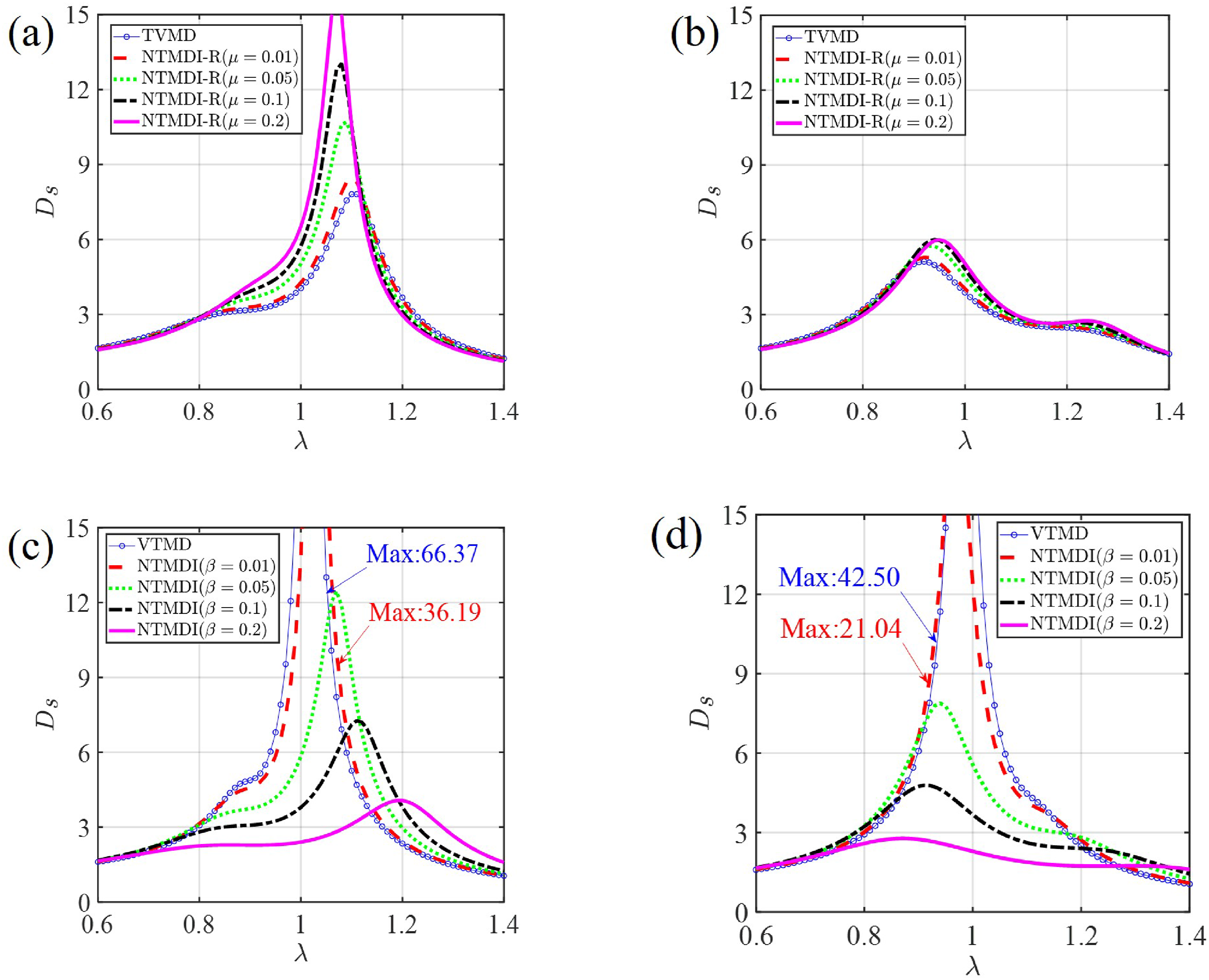
Detuning in optimal damping ratio
Figure 12 presents the frequency response curves of the primary structure for the four control systems under optimal damping ratio detuning. The positive, zero, and negative values of γ
ξ
correspond to positive, no, and negative damping ratio detuning, respectively. All results are obtained under µ = 0.01 and β = 0.1. Figure 12 shows that as the degree of damping ratio detuning increases, the peak response values of the primary structure for all four control systems exhibit minimal changes, indicating that all systems maintain robust performance under both positive and negative damping detuning. Additionally, NTMDI and NTMDI-R exhibit consistent performance, indicating that the connection orientation does not significantly impact the robustness of the control system under damping ratio detuning. Frequency-response curve of the primary structure under optimal damping ratio detuning: (a) γ
ξ
= −5%, (b) γ
ξ
= −10%, (c) γ
ξ
= −20%, (d) γ
ξ
= 5%, (e) γ
ξ
= 10%, (f) γ
ξ
= 20%.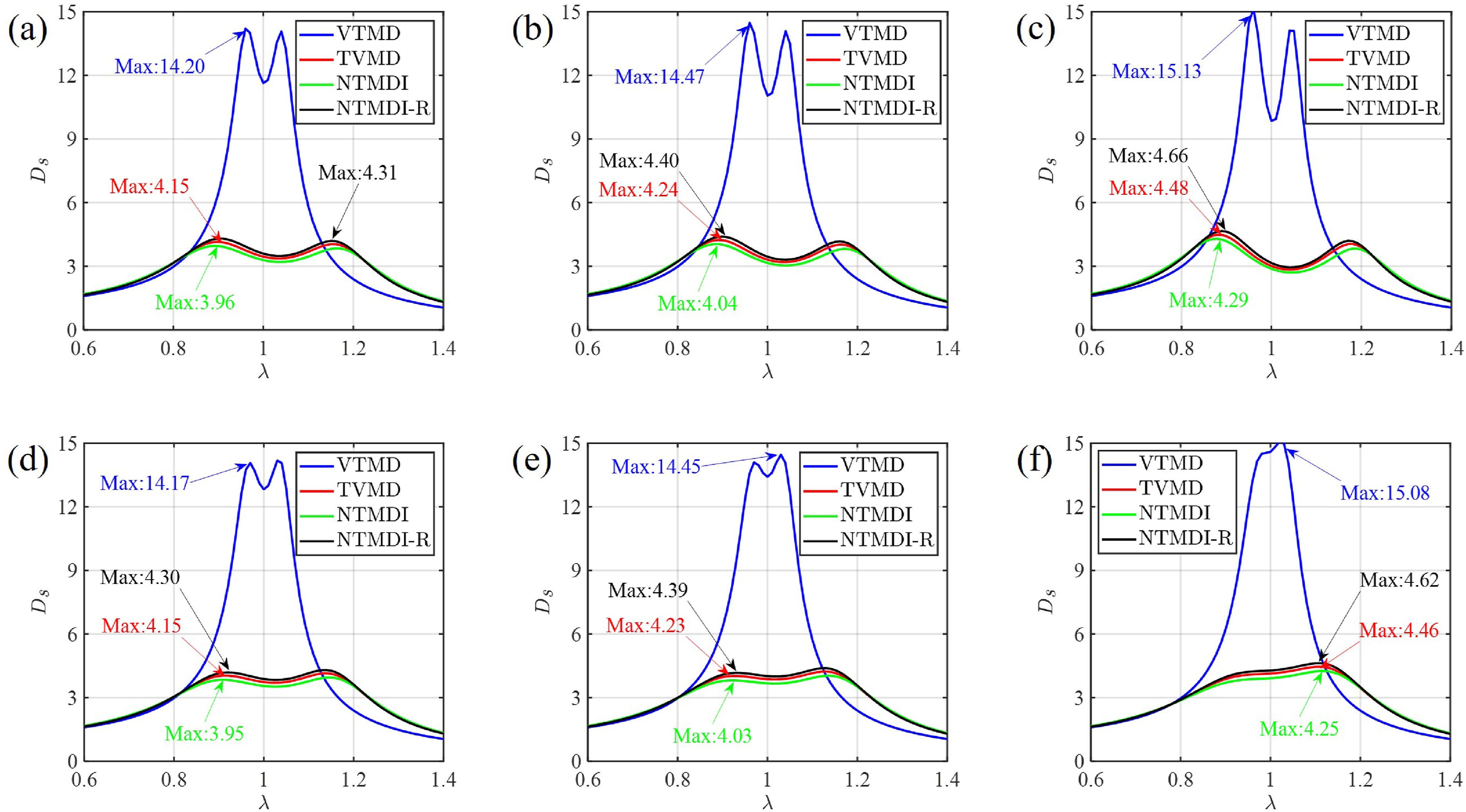
To investigate the effects of mass ratios (μ and β) on the effectiveness of NTMDI and NTMDI-R under optimal damping ratio detuning, Figure 13 present the frequency response curves of the primary structure at γ
ξ
= ±10%. Figure 13(a) and (b) show that damping ratio detuning causes the frequency response of NTMDI-R to change from a symmetric double-peak to an asymmetric double-peak: the left peak is larger under negative damping ratio detuning, while the right peak is larger under positive damping ratio detuning. As µ increases, the effectiveness of NTMDI-R deteriorates under both positive and negative damping ratio detuning. Figure 13(c) and (d) indicate that the effectiveness of NTMDI gradually improves under both positive and negative damping ratio detuning as β increases. Frequency response curves of the primary structure under optimal damping ratio detuning: (a) γ
ξ
= −10%, β = 0.1, (NTMDI-R), (b) γ
ξ
= 10%, β = 0.1, (NTMDI-R), (c) γ
ξ
= −10%, µ = 0.01, (NTMDI), (d) γ
ξ
= 10%, µ = 0.01, (NTMDI).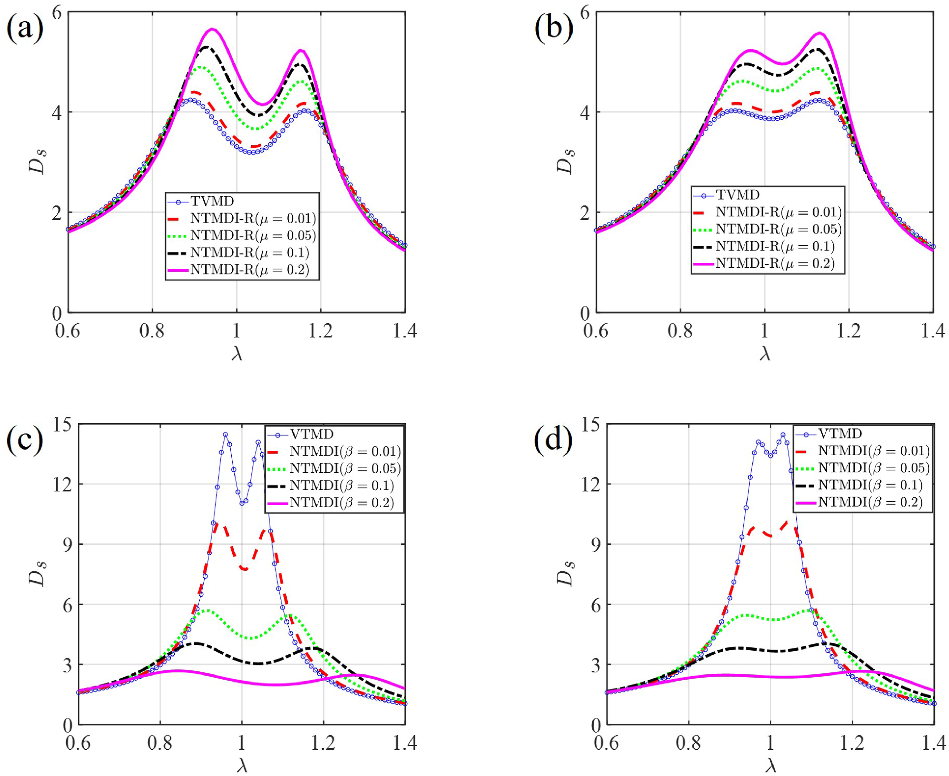
White noise excitation
Figure 14 illustrate the mean square responses of the primary structure for NTMDI and NTMDI-R under the optimal frequency ratio and damping ratio detuning, with parameters set to µ = 0.01 and β = 0.1. The results indicate that damping ratio detuning has a minimal impact on the mean square responses of NTMDI and NTMDI-R. However, negative frequency detuning significantly increases the mean square responses of the primary structure, leading to a notable decrease in robustness for both systems. Effect of frequency and damping detuning on mean square response of the primary structure equipped with NTMDI or NTMDI-R: (a) Three-dimensional drawings, (NTMDI), (b) Top view, (NTMDI), (c) Three-dimensional drawings, (NTMDI-R), (d) Top view, (NTMDI-R).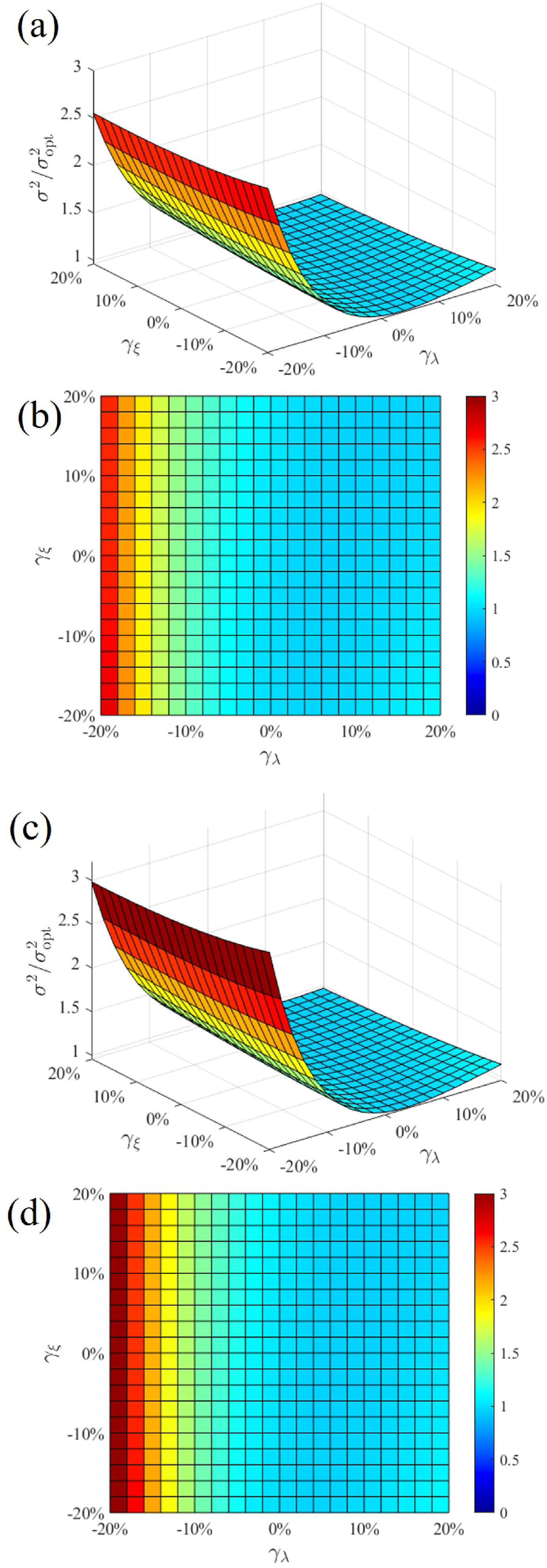
Figure 15 compares the robustness of four control systems under white noise excitation. The results in Figure 15 are based on parameters µ = 0.01 and β = 0.1. Figure 15(a) shows that under frequency detuning, the robustness of TVMD, NTMDI, and NTMDI-R is similar and superior to that of VTMD. However, under negative frequency detuning, the robustness of all four control systems decreases. Figure 15(b) indicates that damping ratio detuning has a minimal impact on the mean square responses of the primary structure for all four control systems, suggesting that damping ratio detuning has little effect on system robustness. Comparison of robustness for four control systems under white noise excitation: (a) Frequency detuning, (b) Damping detuning.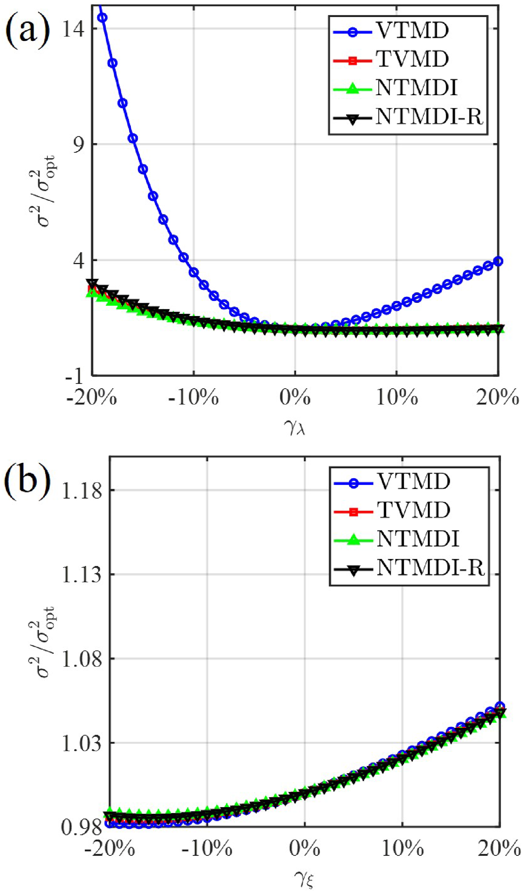
Conclusions
This paper investigates the effects of connection orientation on the optimization, performance, and robustness of a novel tuned mass damper inerter. First, NTMDI and its reversed connected orientation (NTMDI-R) are optimized based on fixed-point theory. Then, their vibration mitigation performance and robustness under harmonic and white noise excitations are analyzed and compared with those of VTMD and TVMD. The main conclusions are as follows. (1) Similar to NTMDI, the frequency response curve of a single-degree-of-freedom structure with NTMDI-R also conforms to the fixed-point theory. Based on this, the optimal parameters of NTMDI-R under harmonic loading (including base acceleration and force) are derived. Due to differences in connection orientations, NTMDI and NTMDI-R exhibit significant differences in optimal parameters and control performance. Under the same physical and apparent mass conditions, NTMDI achieves better vibration suppression and a wider control bandwidth than NTMDI-R. (2) Physical mass is the primary factor responsible for the performance degradation of NTMDI-R. As physical mass decreases, the optimal parameters and effectiveness of NTMDI-R gradually approach those of NTMDI. However, as physical mass increases, the vibration mitigation performance of NTMDI-R significantly declines. Mechanism analysis indicates that the inverse effect of physical mass amplifies the external forces generated by acceleration excitation, thereby reducing the effectiveness of NTMDI-R. (3) The robustness of NTMDI and NTMDI-R is not affected by connection orientation or load type. Both exhibit strong robustness under damping detuning and positive frequency detuning; however, their robustness is significantly reduced under negative frequency detuning. Furthermore, under frequency and damping detuning conditions, the physical mass remains the primary factor contributing to the performance degradation of NTMDI-R. (4) Under harmonic and white noise excitation, NTMDI exhibits superior control performance compared to VTMD. When the apparent mass ratio is between 0 and 0.2, NTMDI-R exhibits inferior control performance compared to TVMD. However, when the ratio exceeds 0.2, NTMDI-R outperforms TVMD. In terms of robustness, all four systems demonstrate similar robustness under damping detuning. However, under frequency detuning, VTMD without apparent mass exhibits the poorest robustness, confirming the critical role of apparent mass in enhancing the system’s detuning resistance.
It should be emphasized that this study does not aim to propose a new configuration (NTMDI-R), but to reveal the differences in parameter optimization, vibration reduction performance, and robustness of NTMDI under forward and reverse connection schemes. Although the effectiveness of NTMDI-R is slightly lower than that of NTMDI, this comparison remains valuable, providing new insights into the design and application of such devices. In addition, the response of NTMDI under actual seismic excitations has been thoroughly investigated in Li et al. (2023); therefore, this aspect is not repeated in the present study.
Footnotes
Funding
The authors disclosed receipt of the following financial support for the research, authorship, and/or publication of this article: This project is jointly funded by the National Natural Science Foundation of China (Grant No. 52378508) and the Science and Technology Innovation Program of Hunan Province (Grant No.2024RC1031).
Declaration of conflicting interests
The authors declared no potential conflicts of interest with respect to the research, authorship, and/or publication of this article.