This study presents the aerodynamic stability and dynamic instability of hierarchical cylindrical shells reinforced with carbon nanotubes (CNTs) and surface-bonded piezoelectric composite films. The analysis employs double-ended free boundary conditions under hygrothermal environment, explicitly accounting for the relationship between material properties and hygrothermal effects. Fundamental kinetic equations of the CNT-reinforced, piezoelectrically layered cylindrical shells are derived from Love’s classical thin-shell theory, which excludes the pyroelectric effects of the piezoelectric layers. The Rayleigh–Ritz method is employed for the numerical solution of the dynamic equations, through combining with Bolotin’s approach. Chebyshev polynomials discretize the displacement fields. In the meanwhile, aerodynamic loading is characterized using first-order linear piston theory with airflow deflection. Furthermore, the analysis systematically examines the influence of critical parameters, including Mach number, airflow deflection angle, CNT volume fraction, fiber orientation angle, temperature, humidity, static load parameters, piezoelectric layer properties, and applied voltage, on the aerodynamic stability boundaries and regions of dynamic instability.
Composite-layered cylindrical shell has been widely used in the field of diverse specializations, ranging from mechanical, civil, aerospace, to architectural engineering. The composite hierarchical cylindrical shells reinforced with CNTs has attracted considerable interest in aerospace applications due to their superior material properties and design flexibility. These structures are frequently exposed to complex loading conditions, such as aerodynamic, thermal, and hygroscopic effects. Consequently, a critical investigation of CNT-reinforced hierarchical cylindrical shells is essential in aerospace applications.
In recent years, CNTs have been increasingly employed to reinforce the matrix phase of composite materials, owing to their excellent specific strength and stiffness. However, CNT composite materials experience significant sensitivity to hygrothermal effects, especially under combined hygrothermal-mechanical loading. As shown by Adams and Miller (1977), Bowles and Tompkins (1989), and Boukhoulda et al. (2006), such environmental exposure progressively degrades their elastic modulus and overall mechanical strengths.
Contemporary studies demonstrate the problem through the lens of CNT distribution, which are typically assuming either homogeneous dispersion or functionally graded (FG) patterning within the matrix, and idealized boundary conditions, such as commonly simply-supported (S-S) or clamped-clamped (C-C) at the ends. For instance, the work by Arani et al. (2019) used Third-Order Shear Deformation Theory (TSDT) coupled with linear piston theory to investigate how FG-CNT material gradation, yaw angle, and geometry dictate aerodynamic stability boundaries. This naturally leads to considerations of boundary constraint effects, as compared for aeroelastic stability by Asadi and Wang (2017) through S-S and C-C configurations. Further probing the dynamic consequences of supersonic flow, Avramov et al. (2019) examined the nonlinear self-excited vibration in S-S FG-CNT shells with the harmonic balance method. Chakraborty et al. (2021) further analyzed the parametric instability of open FG-CNT shells under periodic loading, incorporating Rayleigh structural damping. While, Heydarpour and Malekzadeh (2018) quantified the influence of rotational speed and FG-CNT gradation on the instability regions. In further, Mohammadi et al. (2021) tackled the challenging case of axially moving shells with time-varying velocity using multiscale analysis. Efforts on control are also made by Zhang et al. (2017) who explored nonconstant aerodynamic stability and demonstrated flutter suppression strategies in S-S FG-CNT shells using the principle of energy diversity. In terms of the thermal buckling of cylindrical shells, Heidari-Soureshjani et al. (2024a) established a sophisticated multi-field analytical framework to reveal novel buckling vibration characteristics of porous FG conical shells under hygrothermal coupling, and explicitly quantify the coupled degradation effects of temperature, humidity, and porosity on both vibration frequency and buckling strength. To expand the structural and thermal analysis, Heidari-Soureshjani et al. (2024b) subsequently investigated the dynamic stability of rotating, high-temperature FG-CNT biconical shells, and employed FSDT and the GDQ method for studying the roles of temperature, rotation speed, joining parameters, and CNT properties. The findings on complex geometries under thermal loads are done by Pakravan et al. (2022), who provided a characterization of the fundamental free vibration and buckling mechanisms governing CNT-reinforced conical shells in thermal environments, based on Haar wavelets and FSDT. Besides, the work also details the influence of geometrical dimensions, boundary conditions, temperatures, and material properties.
While significant research exists on the flutter problem in CNT-reinforced functionally graded cylindrical shells under simply supported and clamped boundary conditions, the flutter and dynamic instability boundaries for multi-layered CNT-reinforced cylindrical shells under free-free (F-F) boundary conditions remains unaddressed. This gap is critical given the extensive use of F-F cylindrical shells in aerospace structures, , such as the intercontinental ballistic missile bodies and rocket engine thermal insulation liners, where high-speed flight subjects them to supersonic airflow and thrust oscillations (Li et al., 2018). Addressing this need, the present study introduces two key advancements. Firstly, the effective material properties of the CNT-reinforced multi-layered cylindrical shells are characterized using the Mori-Tanaka micromechanical method, departing from the less accurate mixture rule commonly employed in prior FG-CNT studies. Secondly, we derive discrete flutter and dynamic instability models for F-F boundary conditions by directly applying the Ritz minimization procedure to the Lagrange energy functional. The proposed methodology and resulting findings have been rigorously validated against established literature. Furthermore, aeroelastic stability boundaries and dynamic instability for F-F hierarchical shells under supersonic flow conditions are systematically studied.
Numerical approach and model development
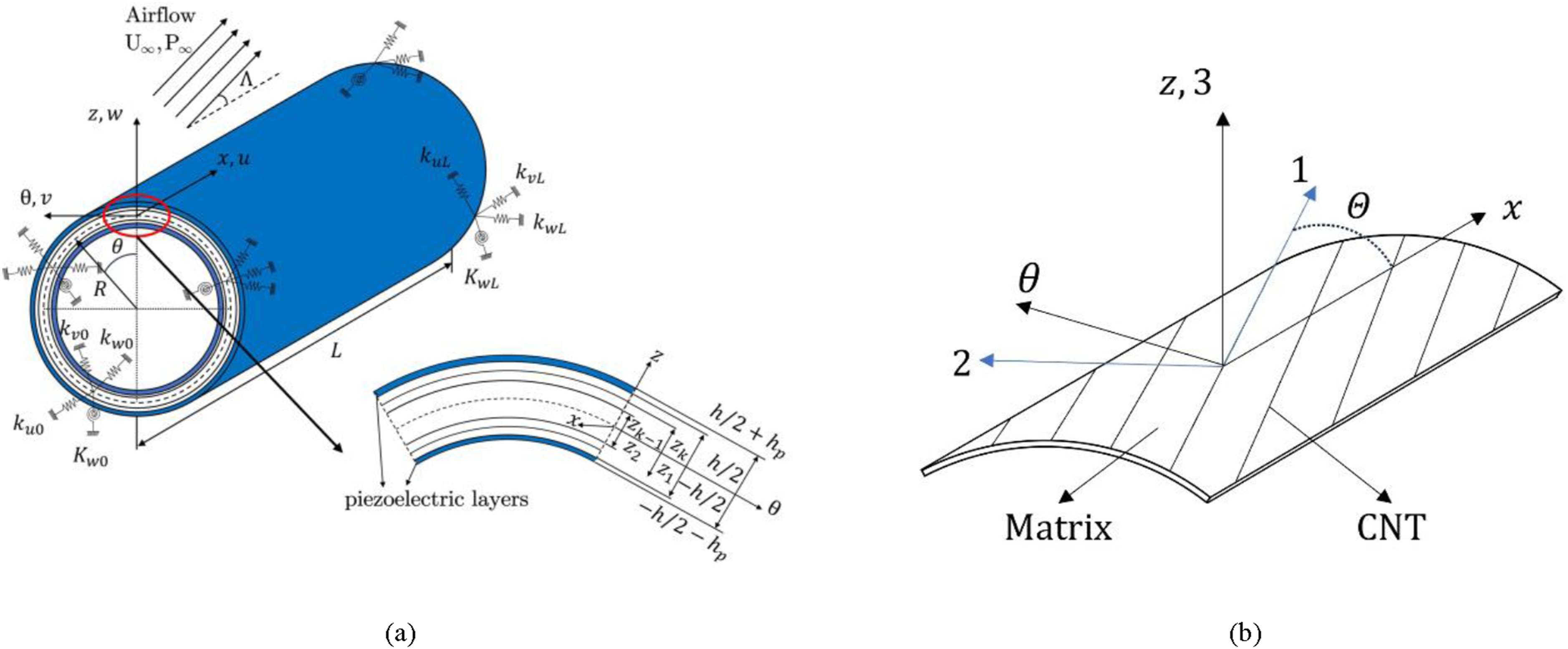
Figure 1(a) illustrates the geometrical size of a CNT-reinforced composite cylindrical shell structure with surface-bonded piezoelectric actuator layers on both inner and outer surfaces. Boundary conditions are implemented via an artificial spring methodology, which represent schematically at the shell edges with associated stiffness coefficients. The plane, marked by the dashed line, signifies the midplane equally distant from top and bottom surfaces of the shells. represents the length of the shells, while represents distance from the center of the circle to the mid-plane. The overall thickness of the primary composite shells, , is calculated as the sum of the thicknesses of each layer. Furthermore, represents the thickness of the piezoelectric plies. The coordinate system defines as the axial direction, as the circumferential direction, and as the normal direction relative to the midplane. As depicted in Figure 1(b), axes represent the material’s principal longitudinal, transverse, and normal directions, respectively, where denotes the counterclockwise angle between the shell’s axial line ( axis) and the CNT fiber axis ( axis).
(a) CNT reinforced multilayer cylindrical shells with piezoelectric layers in supersonic flow subject to spring constraints and local enlargement diagram. (b) Single-layer linear CNT reinforced composite shells and coordinates.
Material parameter
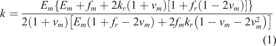
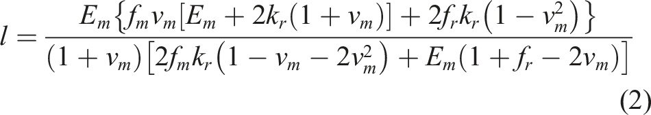
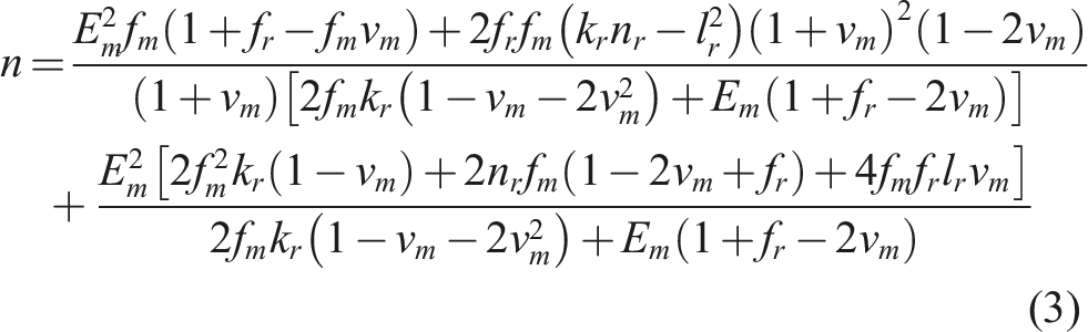
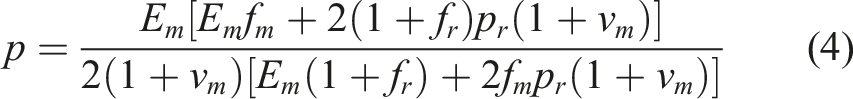
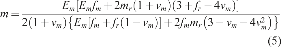
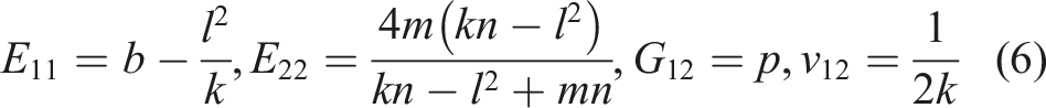
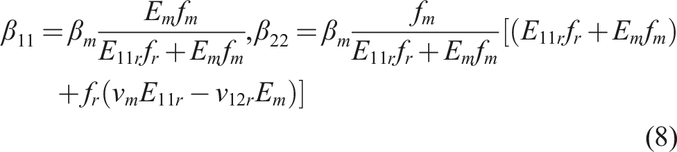
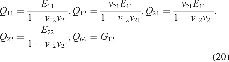
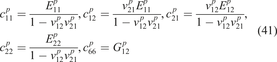
We employ the Mori–Tanaka micromechanical model to study the effective material properties of CNT-reinforced cylindrical shells. Specifically, straight CNTs are embedded in the cylindrical shell matrix to enhance mechanical performance, with the horizontal orientation angle defined between the CNT fibers and the shell’s symmetry axis. The Hill’s elastic modulus of the composite can be expressed as (Hill, 1965)
where in above equations, , , , , represent the Hill’s modulus of elasticity of CNT fibers, and represent the modulus of elasticity and Poisson’s ratio of the matrix, means the percentage of carbon nanotubes in the matrix, that is, the volume fraction. Accordingly, the effective parameters of the material of CNT reinforced composite, including elastic modulus, modulus of shear and Poisson’s ratio, can be given as (Bisheh et al., 2020)
Hydrothermal expansion coefficient of composite’s plies
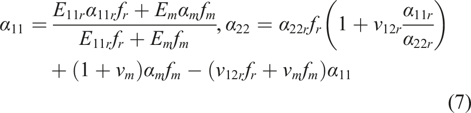
According to Bisheh et al. (2020), the principal longitudinal () and transverse () thermal expansion coefficients (CTEs) for composite material are described as
where the elastic modulus of CNTs and matrix can be written as and . The coefficients of thermal expansion (CTEs) for the matrix phase is indicated by . For the reinforcing fibers, the longitudinal and transverse orientations CTEs are represented by and , respectively. Additionally, and denote the Poisson’s ratios for the matrix and the reinforcing fibers, correspondingly. Ignoring coefficients of moisture expansion (CMEs) of fibers (Bisheh et al., 2020), the principle longitudinal and transverse CMEs for the fiber-reinforced composite are given as
where is the CMEs of the matrix.
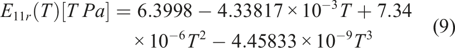
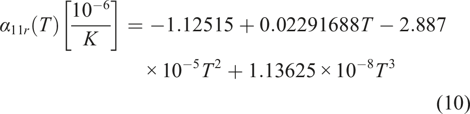
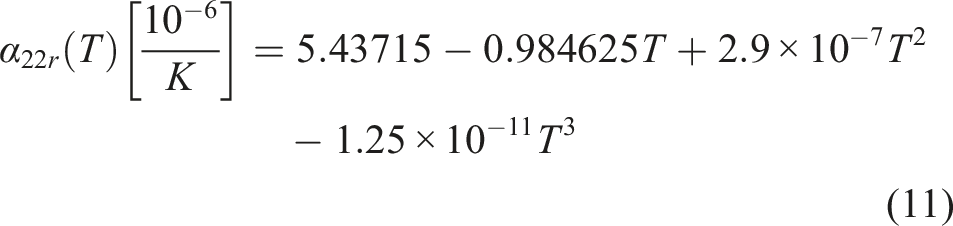
To assess the thermomechanical properties of CNTs as a function of temperature, a third-order interpolation method is employed, as detailed below (Dat et al., 2020)
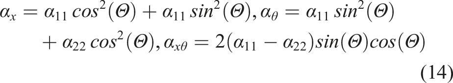
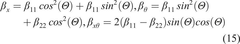
In calculation of equations (9)–(11) , where is the reference temperature. The CTEs and CMEs of composite structures are described by , , and , these coefficients can be transformed into general coordinates as follow
Constitutive relation and energy
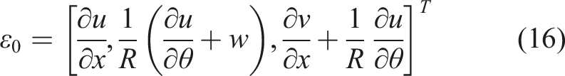
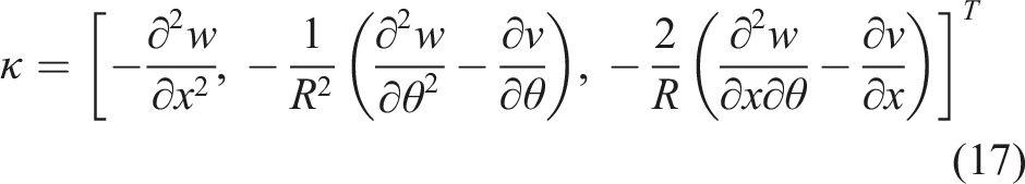
The Love classical shells theory indicates the relationship between its mid-surface displacement and strain as follows
where , are components of membrane strain and curvature variation of the curved surface in the shells with cylindrical geometry, correspondingly. The components of the displacement of the coordinate system at arbitrary points in the mid-plane can be characterized as , , and . The components of strain field at arbitrary points on the shells can be summarized as
where represents the sector of mechanical in-plane deformations at any location inside the cylindrical shells, which depends on the reference surface in-plane strains, the vertical distance from this surface, and the shells’ in-plane curvatures.
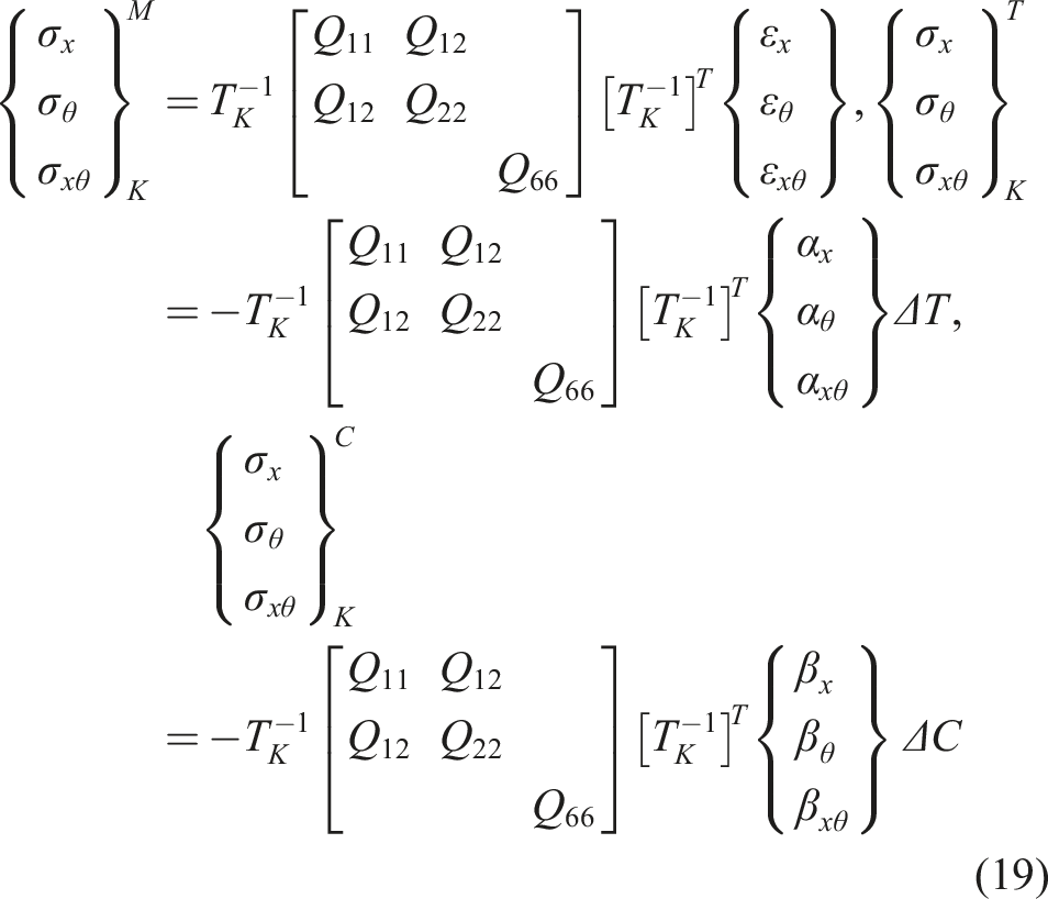
When subjected to mechanical and hygrothermal loads, the in-plane stress distributions within the laminate can be mathematically described as follows
where superscript , , and stand for mechanical, thermal, and moisture stress, correspondingly. and represent the variations in temperature and humidity. The coordinate transformation matrix as follows
The three stress vectors in equation (19) can be, respectively, abbreviated as
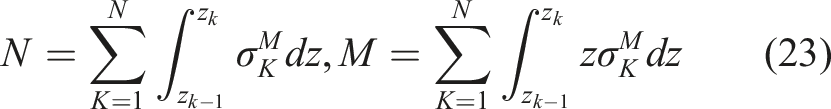
By summing the integrals of stress over each thickness of the shells can evaluate the internal force and moment
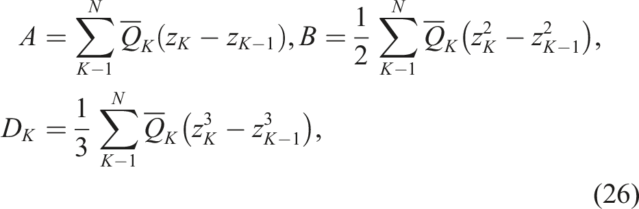
where is used to represents the aggregate number of composite plies, whereas and denote the coordinates of the layer, respectively. By substituting equation (23) into equation (22) and integrating over the aggregate thickness of the main shells yields the following results
where A, and are the stiffness matrix of membrane, stiffness matrix of coupling and stiffness matrix of bending of the composite cylindrical, correspondingly, and
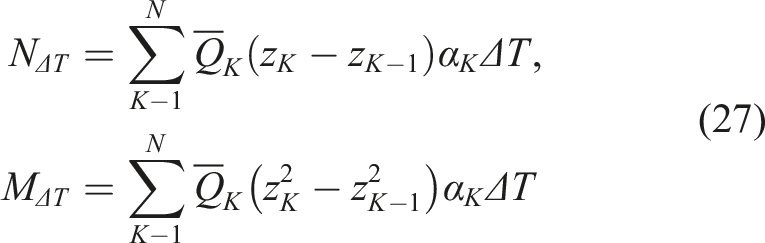
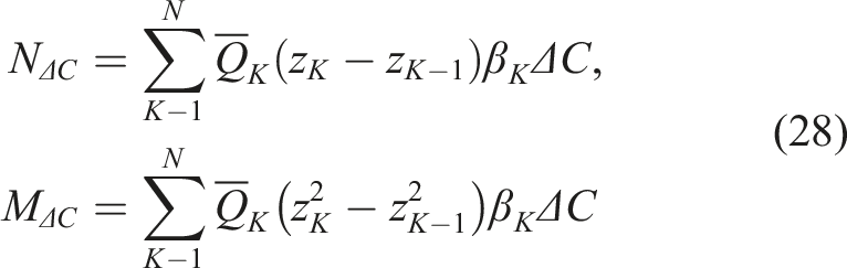
Similarly, and are used to represent the force and moment resultant vectors induced by thermal effects in the host substrate laminated shells, correspondingly. , are the force and moment tensor caused by humidity-induced of the host substrate hierarchical shells, and they can be characterized as
where ,
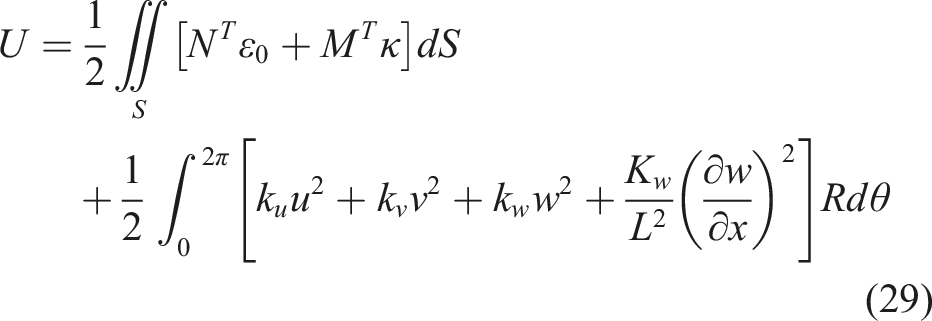
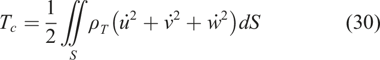
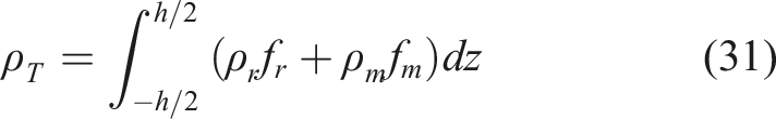
The energy of the hierarchical shells structure, which encompasses the strain energy as well as the energy of spring and kinetic, can be characterized as follows
where is computed by integrating (carbon nanotubes) and (matrix)
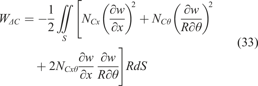
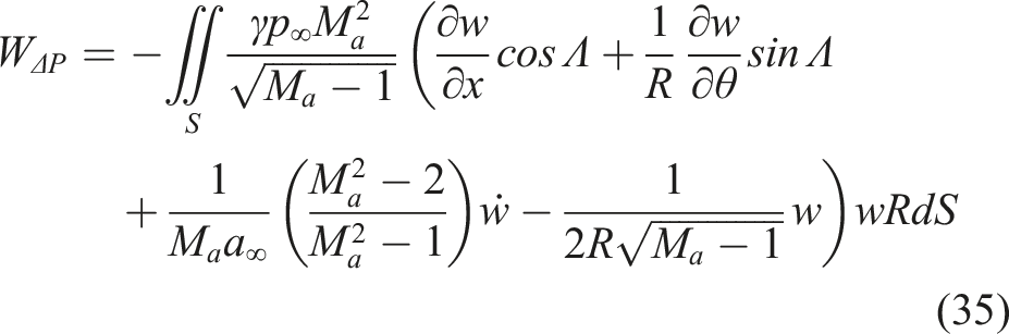
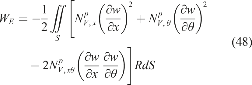
The work done by the hygrothermal loads are expressed as (Wang et al., 2023)
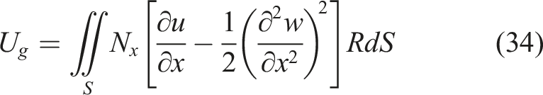
The energy due to the application of an axial compressive force can be represented as (Asadi and Wang, 2017)
where , , , , are the air adiabatic index, the static pressure due to the air flow, the local sonic velocity, the Mach number and the airflow deflection angle, respectively.
Constitutive relation of piezoelectric film
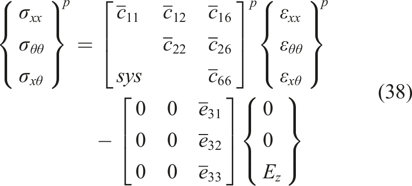
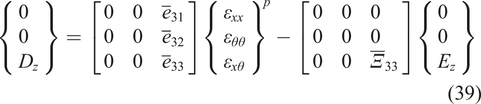
The piezoelectric film, having a thickness denoted as , are adhered to the external and internal edges of the primary hierarchical shells, as shown in Figure 1(b). Polarization is achieved by applying an external electric field in the thickness direction. The coupled electromechanical constitutive equation for a piezocomposite layer is presented as follows (Chai et al., 2017)
The above condensed form of equations further expanded as below
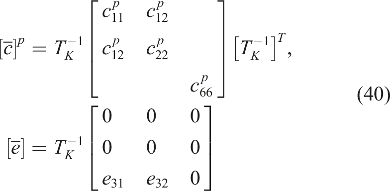
where the superscript indicates that the stress and strain parameters in above equations correspond to the physical properties of the piezoelectric fibers. The tensor represents the stress, the tensor represents the strain, the stiffness matrix, once transformed and reduced, is identified as , the matrix represents the piezoelectric constant, the tensor represents the dielectric constant, the tensor depend with voltage and the tensor denotes the electric displacement of an piezoelectric material. The angle-ply of the piezoelectric fibers is defined as, the transformation matrix is also based on equation (21), but with the variable replaced by the variable. and can be expressed as
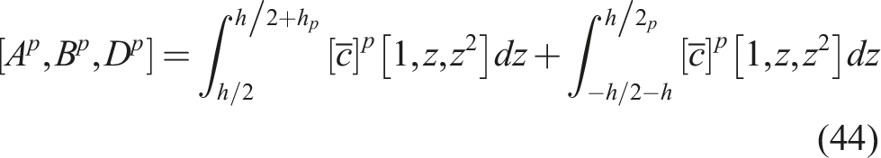
where , , , and are be used to mean the modulus of elastic, modulus of shear, and Poisson’s ratio associated with the piezoelectric fibers, correspondingly. Further, the force resultant vector , moment resultant vector of the piezoelectric layer can be represented as
where , , and are the matrix of membrane stiffness, matrix of coupling stiffness and matrix of bending stiffness of the piezoelectric film, correspondingly.
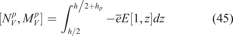
Only the outer piezoelectric film is used as the actuator, and represent the force and moment resultant vectors, respectively, induced by voltage in the outer piezoelectric layer
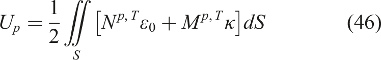
The energy of strain and energy of kinetic associated with the inner and outer piezoelectric film can be formulated as
where represents the mass surface density of the piezoelectric film. The energy done by the voltage applied on the outer surface piezoelectric film is attained as (Zhou et al., 2019)
Governing equations
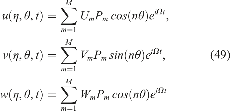
The displacement field of a multi-layered cylindrical shell can be mathematically expressed in terms of axial orthogonal polynomials combined with circumferential Fourier series
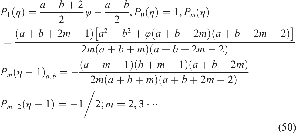
where the unknown coefficients can be named by , , and , the angular frequency can be denoted by ,the mode number of the shells in the and directions can be expressed by and , the regular expression for the first kind of Chebyshev polynomials, denoted as , can be described as follow
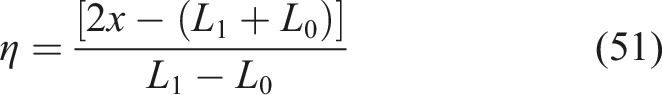
Since the Chebyshev polynomial is defined within the range of , this study necessitates a transformation of its domain from to ,while
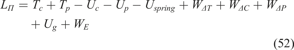
By substituting equation (49) into equations (29)–(35), and (46)–(48), the Lagrange energy functional associated with the CNT-reinforced laminated cylindrical shell is formulated as follows
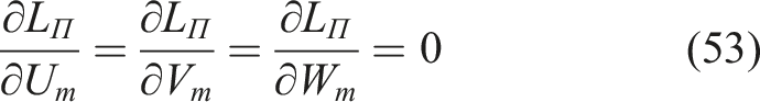
By applying the Ritz minimization procedure to equation (52) with respect to the unknown coefficients, the following result can be obtained
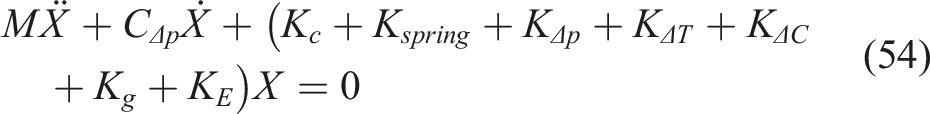
The discrete form of the governing equations can be written as follows
Solution of the governing equations
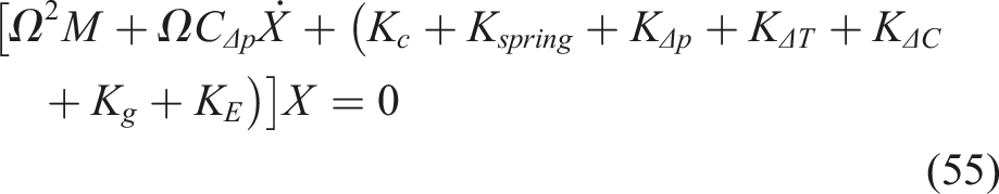
In the aeroelastic analysis, the governing equations are transformed into eigenvalue equations according to the frequency domain analysis method as
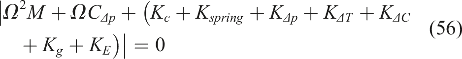
The prerequisite for the preceding equation to have a non-zero solution is
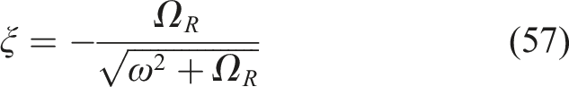
The complex eigenvalue is derived by solving equation (56). The eigenfrequency and the real part of the eigenvalue are named by and , correspondingly. The determination of the system’s damping ratio can be achieved through the following expression
It is widely recognized (Song and Li, 2012) that the point at which the damping ratio transitions from positive to negative signifies the critical flutter pressure .
In the dynamic stability study, the cylindrical shells is considered to be placed under a periodically varying axial load , and , where , are named as the static and dynamic segments of load, correspondingly, and is named as the loading frequency. The critical load for buckling of the shells is named as (Qinkai and Fulei, 2013).
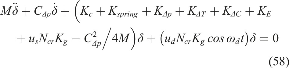
Substituting into equation (54) and using the coordinate transformation to obtain the classical Mathieu-Hill equation as
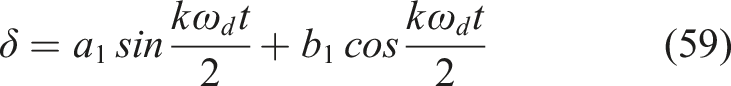
Equation (58) reveals the dynamically stable behavior of the cylindrical shells under periodic load, and its stable and unstable regions can be solved by Bolotin et al. (1965). For the symmetric cylindrical shells, instability region analysis reveals larger period domains than period counterparts, with the period solution formulated as
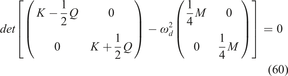
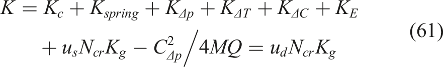
Substituting equation (59) into equation (58) and equating respective sine/cosine coefficients of and yields their discrete linear algebraic system, requiring the coefficient matrix determinant to vanish. Solving the following equation determines the unstable region’s two boundary lines, whose intersection defines its origin
where
Parametric studies
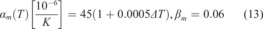
This paper examines aeroelastic/dynamic instability in F-F multilayer cylindrical shells with CNT reinforcement under hygrothermal conditions. Where the CNT mass density is , and Hill’s modulus of elasticity is , , , , and , respectively. For the reinforced matrix phase the material parameters are , , and. For the piezoelectric film the material parameters are , , , , , .
Equation validation
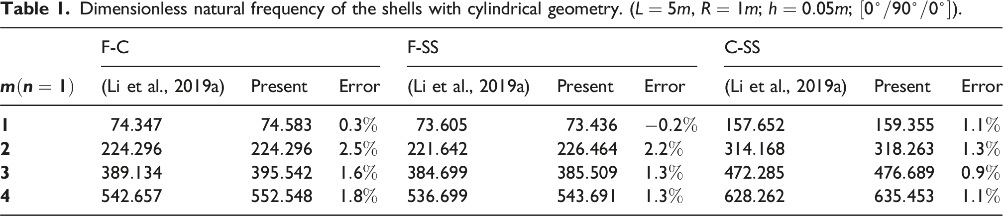
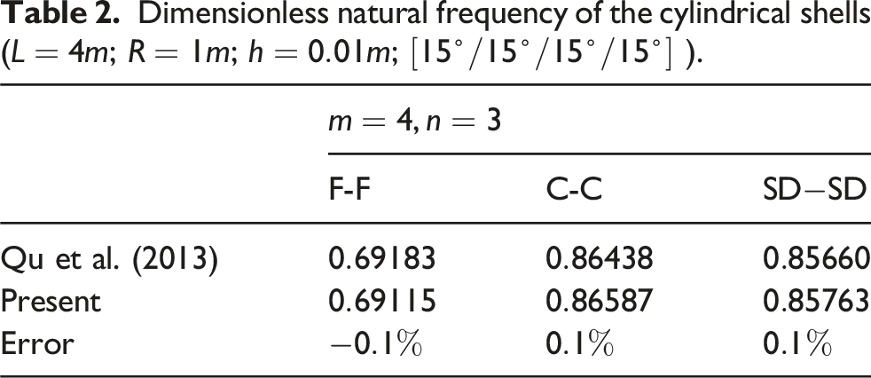
In this section, the derived formulations and computational algorithms were validated through benchmark comparisons against previous literature cases. This verification confirms both analytical correctness and computational efficacy, to provide a rigorous foundation for subsequent parametric investigation of dynamic characteristics. In terms of the first benchmark, the material parameters of the composite cylindrical shell are , , , and , while the dimensionless frequency parameter of the shells can be expressed as . The comparison dates of the dimensionless natural frequency are detailed in Table 1, where three case of boundary conditions are studied, F-C indicates the shells is free at and clamped at , F-SS is left end of free and right end of simply supported, and C-SS is left clamped and right simply supported. The spring stiffness values corresponding to the different conditions of boundary are, F: ; SS: , ; SD: , , and C:. SD indicates boundary condition of soft simply supported. For the second instance, the properties of material of the composite cylindrical shells are , , , , and , while the dimensionless frequency parameter of the shells with cylindrical geometry is .
Dimensionless natural frequency of the shells with cylindrical geometry. (, ; ; ).
The numerical results in Table 1 and Table 2 are in good agreement with the literature results in both the present derivation methodology and the computational reliability of the implemented algorithms.
Dimensionless natural frequency of the cylindrical shells (; ; ; ).
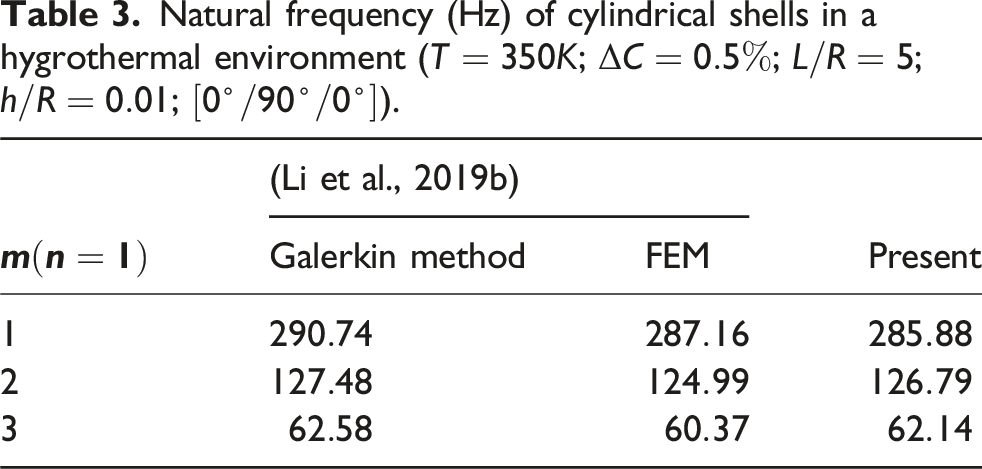
The comparison results of the natural frequency of double-ended clamped cylindrical shells in a hygrothermal environment is presented in Table 3. The environmental parameters are set as , . The geometric parameters of the cylindrical shell are defined as , . The material properties include , , , and . Additionally, the thermal expansion coefficients are and , while the moisture expansion coefficients are and . Comparisons show this study’s results align with literature, validating the derived formulations and temperature- and humidity-related programming.
Natural frequency (Hz) of cylindrical shells in a hygrothermal environment (; ; ; ; ).
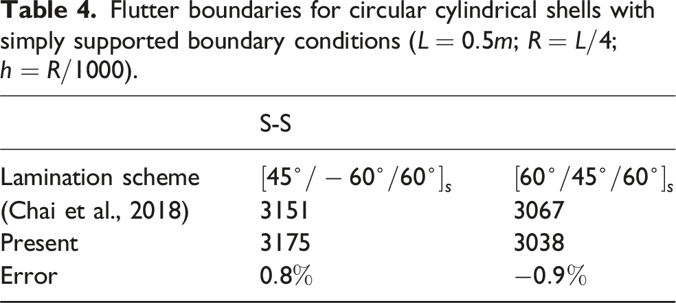
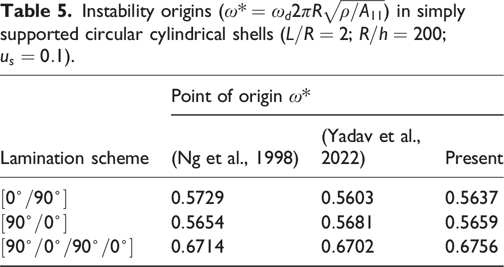
Subsequently, the verification results for the flutter boundary are summarized in Table 4. The geometric parameters of the cylindrical shell used in this case are as follows: , , . The material properties include , , , , . For the dynamic instability verification, the results are presented in Table 5, where the geometric configuration is defined by and , and the material properties are given as , and . As shown in tables, the flutter boundaries and onset points of dynamic instability calculated in this study are in close agreement with those reports in the literature.
Flutter boundaries for circular cylindrical shells with simply supported boundary conditions (; ; ).
The aeroelasticity of laminated cylindrical shells was investigated with the initial volume fraction of CNT reinforced fibers is , the geometrical size of the cylindrical shells are , , and ; the initial airflow related parameters are , , , and, the initial temperature and humidity are and , the layup of the cylindrical shells are layers, and the layup angle is .
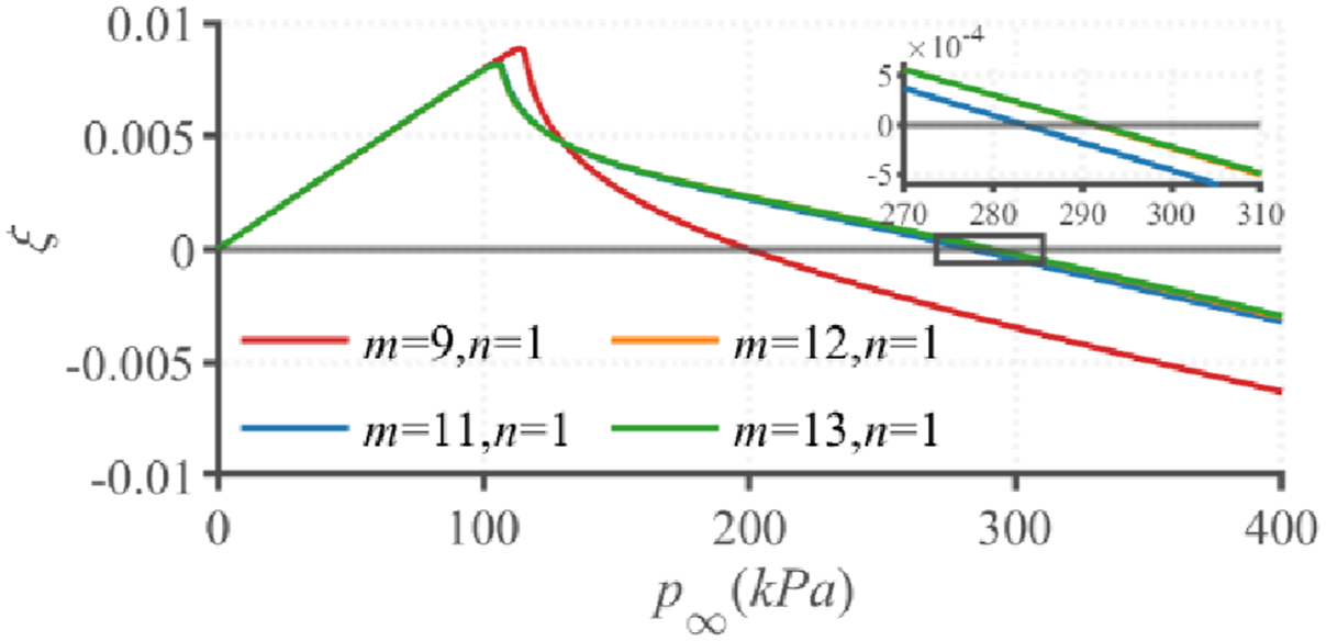
This study first investigated the convergence behavior for flutter boundaries of cylindrical shells under supersonic flow. Figure 2 shows the evolution of critical flutter points versus axial modal truncation order. It can be seen that when the axial truncation order reaches and , the change of the zero-damping point is very small, which shows a good stable convergence result. Subsequently, it is reasonable to select the axial truncation order of .
Flutter boundary under varying axial truncation orders.
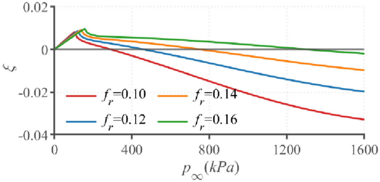
To quantitatively elucidate the impact of carbon nanotube volume fraction, the critical flutter pressure corresponding to various volume fractions is presented in Figure 3. In this figure, we take and . An escalation in the volume fraction results in a corresponding rise in the critical aerodynamic pressure. The reason is increasing the CNT volume fraction might strengthen flexural rigidity through more effective reinforcement mechanisms. The resultant stiffening of the laminated cylindrical shell consequently expands the stability range.
Dependence of flutter criticality on carbon nanotube volume fraction ().
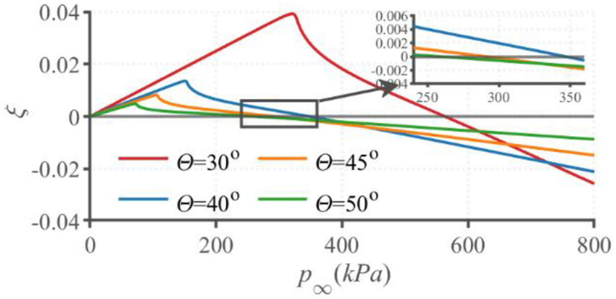
The flutter pressure corresponding to the angle of carbon nanotube fibers is presented in Figure 4. It is seen that the critical point of flutter exhibits a gradual intensify with the layup angle decreasing. This phenomenon is predominantly governed by supersonic axial flow dynamics. Reducing the carbon nanotube fiber orientation angle enhances axial structural rigidity in laminated cylindrical shells. Consequently, CNT cylindrical shells with smaller ply angles demonstrate superior aeroelastic stability characteristics.
Dependence of flutter criticality on .
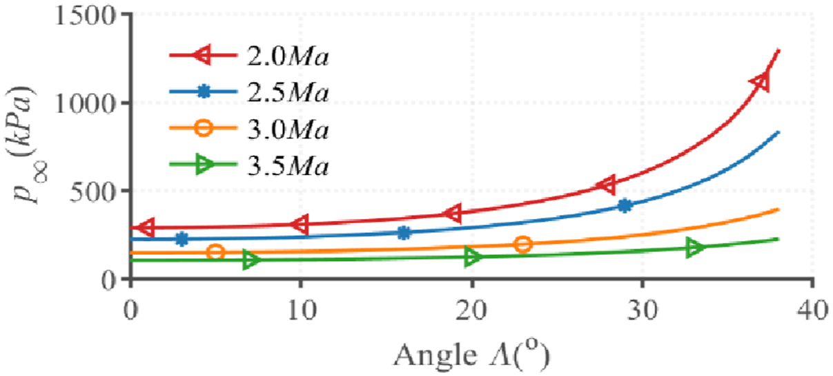
Figure 5 presents the parametric dependencies of critical flutter pressure in composite cylindrical shells, through systematic examination of airflow deflection angle variations and Mach number effect. For example, a cylindrical shell is taken into consideration. Four sets of Mach numbers of , and are involved. It is observed that for all Mach numbers, the critical aerodynamic pressures increase as the airflow deflection angle increases. According to Figure 1 and the influence of CNT ply orientation on critical dynamic pressure, it shows that at CNT ply orientation, increased airflow shell axis angle effectively decreases the angular deviation between airflow and reinforcement fibers. This improved fiber load alignment can improve CNT reinforcement efficacy and structural stiffness. Conversely, higher Mach numbers reduce the flutter pressure at any airflow deflection angle.
Dependence of flutter criticality on (, ).
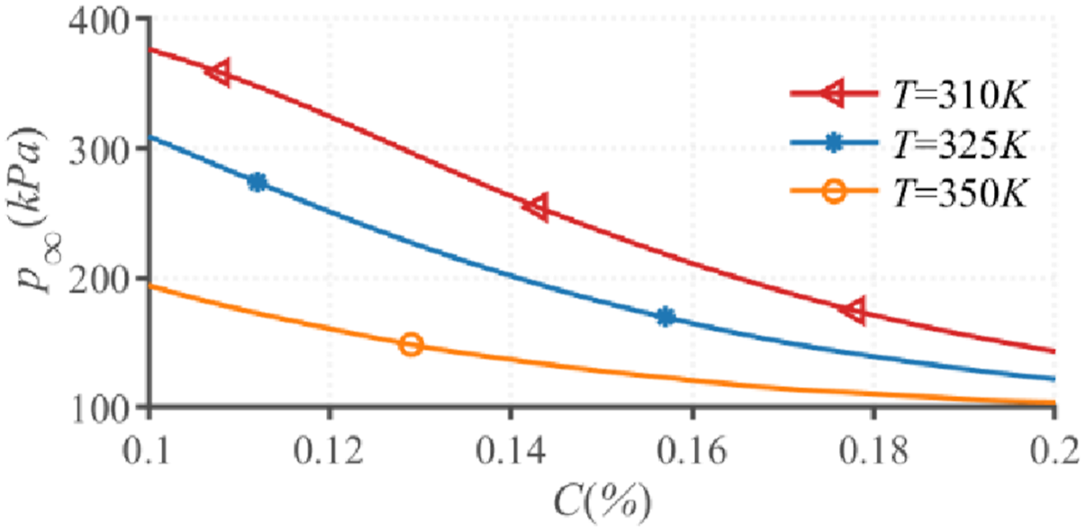
The impact of hydrothermal environment on the critical aerodynamic pressures of the hierarchical shells with cylindrical geometry are illustrated in Figure 6. The findings demonstrate reduced flutter boundaries for hierarchical cylindrical shells under hygrothermal exposure. This degradation originates from temperature- and moisture-induced reduction in elastic modulus, which compromises structural stiffness and consequently destabilizes the system.
Dependence of flutter criticality on the hydrothermal environment ().
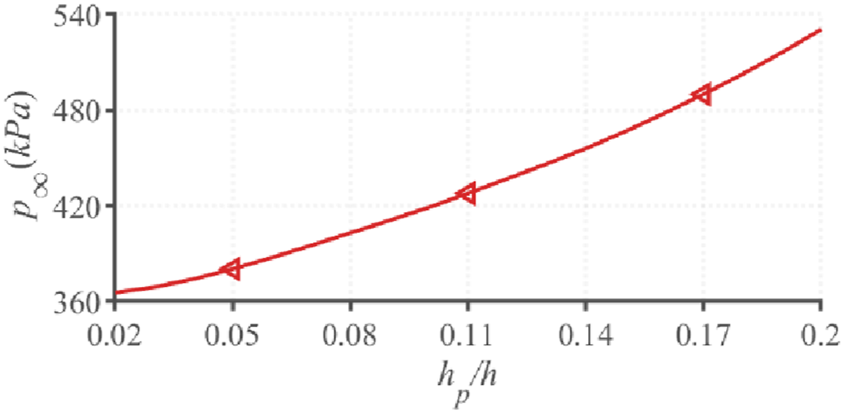
Figure 7 quantifies the relationship between critical aerodynamic pressure and piezoelectric thickness ratio in cylindrical hierarchical shells with surface-bonded piezoelectric films. The critical pressure exhibits direct proportionality to , with progressive increases in thickness ratio yielding exponentially augmented pressure resistance. The main reason is that the increase in macro-fiber composite (MFC) thickness significantly improves the bending stiffness of the hierarchical cylindrical shell
Effect of thickness ratio on critical flutter dynamic pressure.
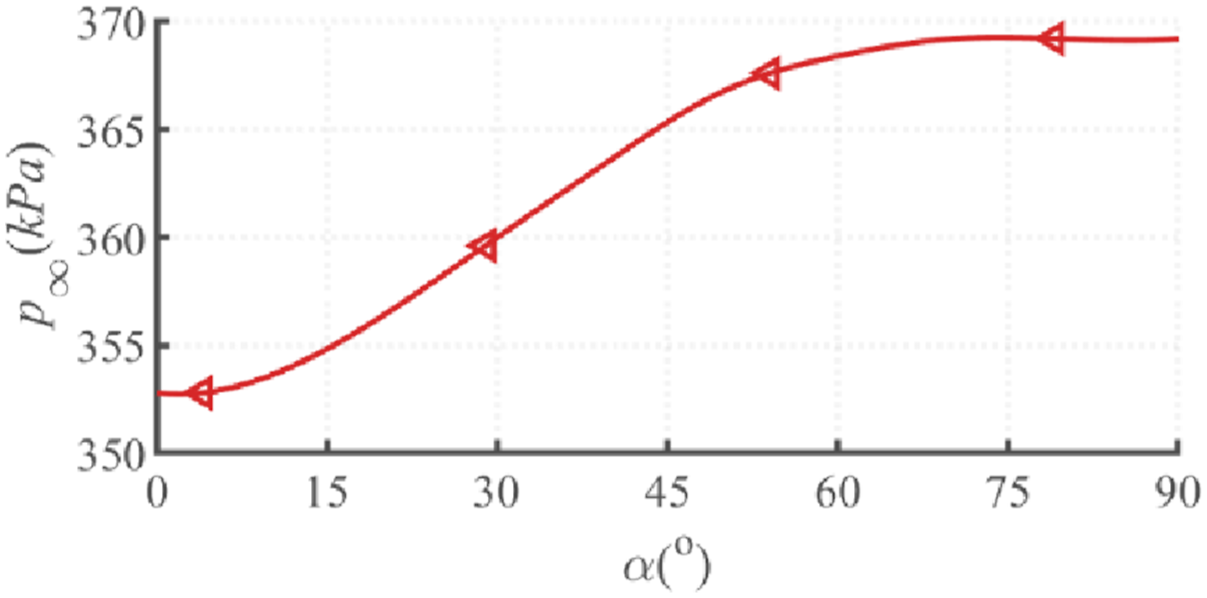
Figure 8 demonstrates that MFC actuator angular orientation significantly affects cylindrical shells’ critical aerodynamic pressure. At thickness ratio and voltage, the flutter boundary increases with piezoelectric fiber angle variation, peaking at .
Effect of MFC angle on critical aerodynamic pressure.
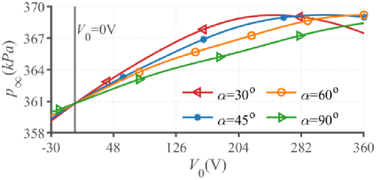
Figure 9 depicts the influence of electric field voltage on flutter pressure for varying MFC fiber orientations in cylindrical hierarchical shells at thickness ratio of . The data demonstrate that an initial increase followed by progressive decay within the range of to . Especially, equivalent critical pressures occur at bias regardless of fiber orientation, which is a baseline condition matching the literature (Zhou et al., 2019). This voltage-neutral response confirms angle independence at zero potential.
Critical aerodynamic pressure as variation of voltage and MFC angle.
Dynamic instability
As discussed in section 2.6 for cylindrical shells subjected to periodic parametric loading, the unstable regions of the hierarchical cylindrical shells coupled with MFC actuators exhibit a complex dependence on multiple parameters. These include aerodynamic loads, Mach number, airflow deflection angle, CNT layup angle, volume fraction, temperature, humidity, static load and applied electric field voltage. The dimensionless critical excitation frequency is named as .
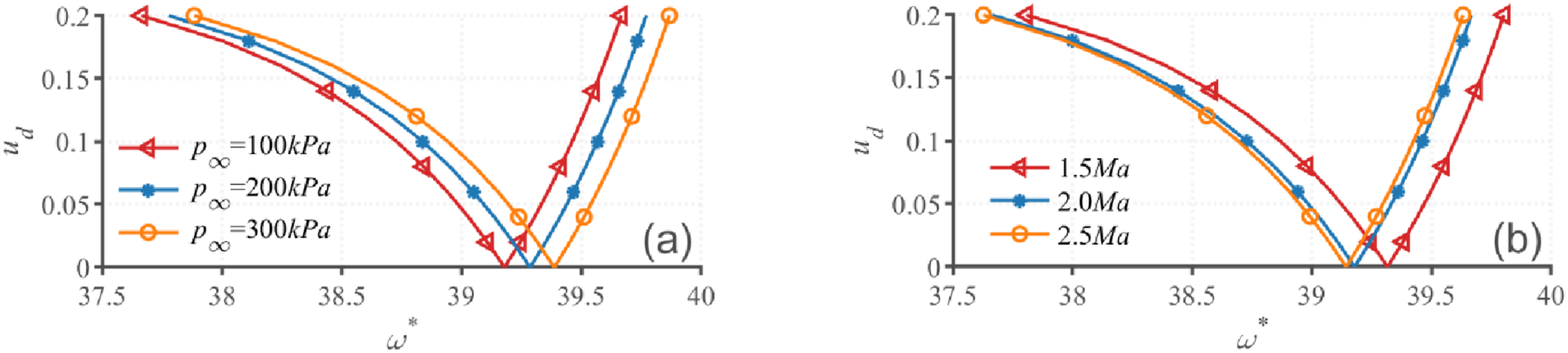
Figure 10(a) illustrates aerodynamic pressure effects on instability regions in cylindrical hierarchical shells under F-F boundary conditions. The V-shaped area formed by three curves delineates unstable regions across varying conditions, with exterior zones indicating stable regions. It can be seen that variations in aerodynamic pressure substantially affect both the extent and positioning of unstable regions. Specifically, an increase in aerodynamic pressure leads to a notable shift of the regions of instability in the direction of the high-frequency band. Elevated aerodynamic pressure increases the natural frequency of laminated composite structures within their operational range, which consequently raise the critical transverse excitation frequency. Figure 10(b) illustrates the influences of three different Mach numbers on the regions of instability of the hierarchical shells. The variation shown in Figure 10 indicates a negative correlation between the shift in the instability domain and the rise in Mach number.
Effects of aerodynamic pressure and Mach number on the regions of instability. (a) (b) .
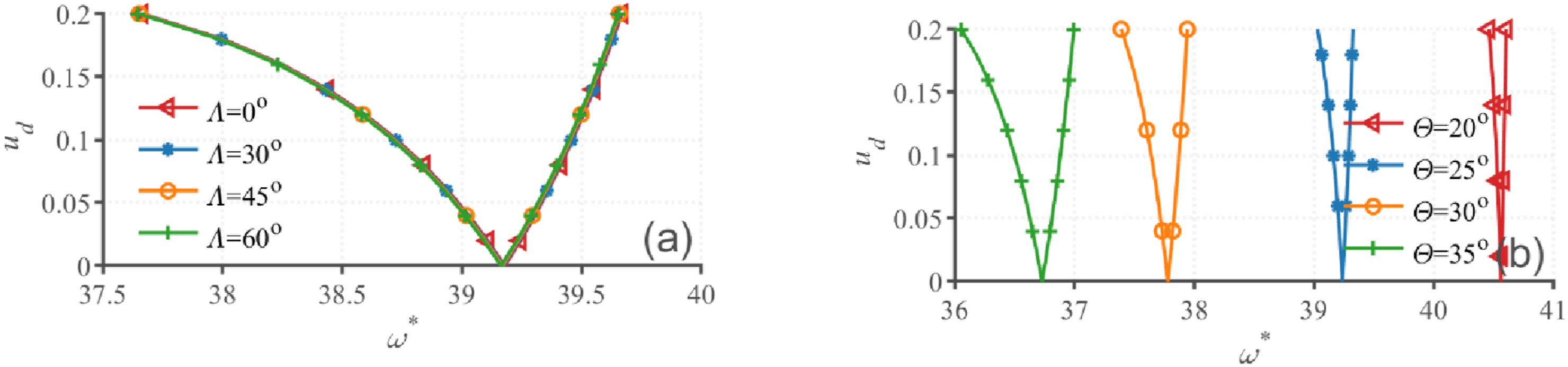
Figure 11(a) demonstrates that the airflow deflection angle exerts negligible influence on instability boundaries. However, the ply angle of the hierarchical shells with cylindrical geometry has a substantial influence on the regions of instability, as shown in Figure 11(b). The results demonstrate that decreasing the ply angle simultaneously might change instability regions toward higher frequencies while reducing their bandwidth. This phenomenon is primarily attributed to the layup configuration, which significantly influences the structural stiffness. In this study, the reduction in ply orientation angle leads to an increase in the structure’s natural frequency, consequently elevating the corresponding critical excitation frequency.
Effects of airflow angle and ply-angle on the regions of instability. (a) . (b) .
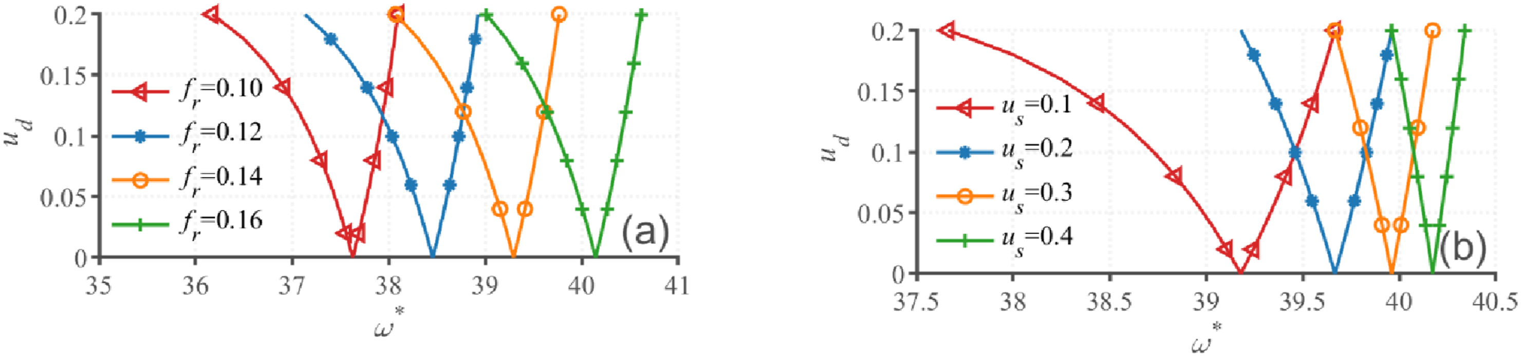
Figure 12(a) examines how the percentage of CNTs influences the unstable regions of the hierarchical shells. As illustrated in the figure, the volume fraction has a substantial impact on the extent of the regions of instability. As the volume fraction increases, the regions of instability shift to a high-frequency band. This phenomenon can be attributed to the fact that the increase in volume fraction improves the bending stiffness of the system. However, the width of this region of instability remains approximately constant. Figure 12(b) demonstrates static load parameter effects on instability regions in cylindrical hierarchical shells. Increased static loads induce backward shifts of instability regions, with concomitant reductions in V-shaped enclosed unstable areas.
Variation of the regions of instability with volume fraction and static load. (a) (b) .
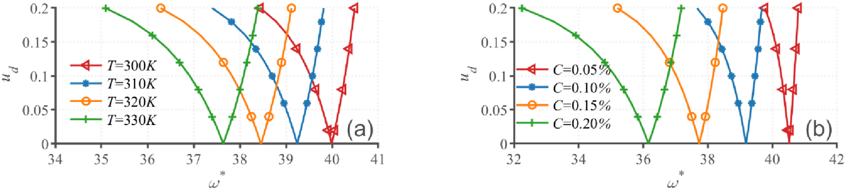
Figure 13 displays instability regions under four temperature/humidity conditions, showing that maximum instability corresponds to elevated temperature and humidity levels, occurring predominantly at lower frequency. This is due to the reduction in the system’s flexural rigidity resulting from the increase in temperature and humidity.
Dependence of unstable regions on temperature and humidity. (a) . (b) .
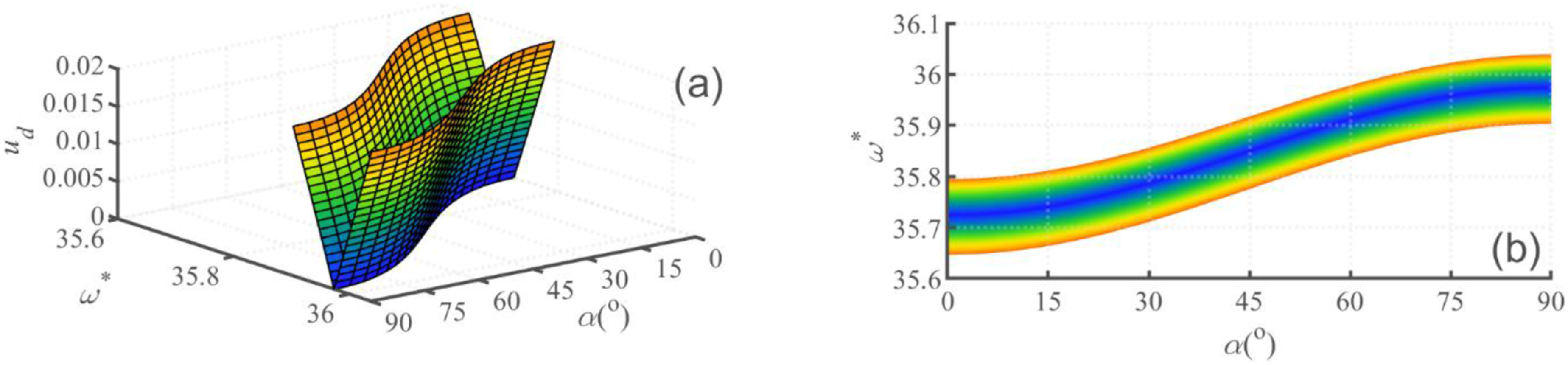
To further illustrate the effect of MFC on the structural regions of instability, Figure 14 demonstrates that increasing the fiber orientation angle () in MFC-integrated hierarchical shells simultaneously influences instability regions toward higher frequencies while reducing their spatial extent, with both trends quantified parametrically across the angular range.
Dependence of unstable regions on MFC angle. (a) and (b) respectively represent the three-dimensional and two-dimensional plane diagrams of the dynamic instability region varying with the MFC angle. ().
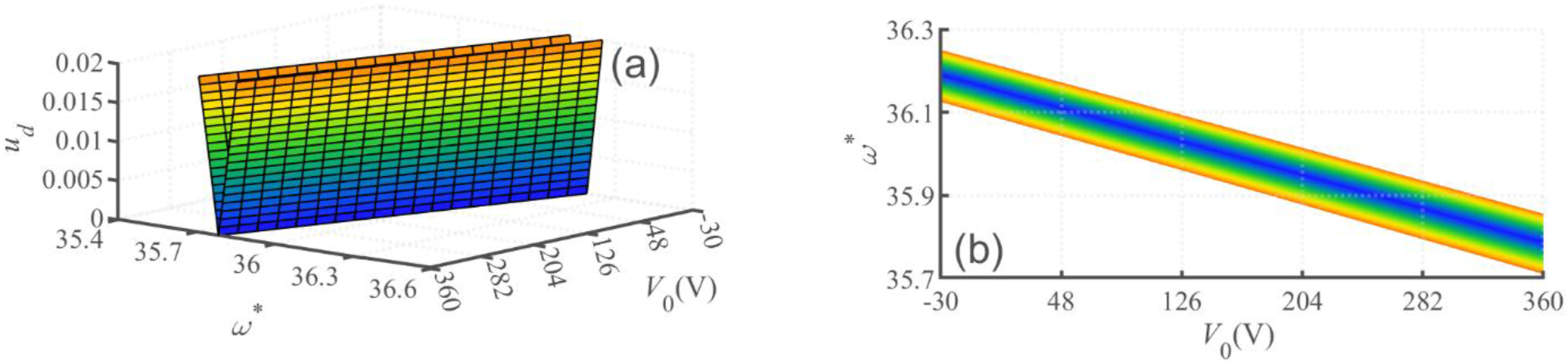
Figure 15 illustrates the implications of voltage on the regions of instability of structural when parameters and . As illustrated in Figure 15(a), for negative voltages, instability domains migrate toward higher frequencies while progressively contracting as voltage magnitude increases. However, positive voltages drive instability toward lower frequencies while expanding its spatial footprint. Transverse polarization in piezoelectric fibers causes the polarity-dependent behavior. Negative voltages induce transverse compression that reduces bending stiffness, while positive voltages generate transverse tension that strengthens structural rigidity. This phenomenon is consistent with findings in the literature (Eftekhar et al., 2018).
Dependence of unstable regions on voltage. (a) and (b) respectively represent the three-dimensional and two-dimensional plane diagrams of the dynamic instability region varying with voltage. ().
Conclusion
This study aims to investigate the aeroelasticity and dynamic instability of multi-layered cylindrical shells reinforced with CNT composites under F-F boundary conditions. We quantify the effects of airflow parameters, CNT volume fraction, fiber ply orientation, temperature, humidity, and voltage on the flutter boundary and dynamic instability boundary. Key findings can be summarized as below.
1. Increasing CNT fiber volume fraction, MFC fiber angle, and thickness ratio while decreasing CNT fiber ply angle, might elevate the flutter and dynamic instability boundaries of double-ended free cylindrical shells, thereby improving the stability of elastic structures. These findings provide valuable insights for the structural design of high-speed flight projectiles from a vibration perspective.
2. Elevated temperature, humidity, and Mach number compromise the flutter and dynamic instability thresholds of double-ended free cylindrical shells. While increased aerodynamic pressure can enhance dynamic instability resistance, this benefit is counterbalanced by its tendency to promote flutter onset. Consequently, missile structural design requires careful multi-parameter optimization to mitigate these competing aeroelastic effects.
3. Voltage variations significantly influence on both flutter and dynamic instability boundaries in double-ended free cylindrical shells. This voltage-dependent control mechanism directly provides future active vibration controller designs for such aerospace structures.
Footnotes
ORCID iD
Yanhong Wu
Funding
The authors disclosed receipt of the following financial support for the research, authorship, and/or publication of this article: The project was supported by the key R&D plan of the province of Heilongjiang. Project No: 2022ZX01A14.
Declaration of conflicting interests
The authors declared no potential conflicts of interest with respect to the research, authorship, and/or publication of this article.
References
1.
AdamsDFMillerAK (1977) Hygrothermal microstresses in a unidirectional composite exhibiting inelastic material behavior. Journal of Composite Materials11: 285–299.
2.
AraniAGKianiFAfshariH (2019) Aeroelastic analysis of laminated FG-CNTRC cylindrical panels under yawed supersonic flow. International Journal of Applied Mechanics11(06): 1950052.
3.
AsadiHWangQ (2017) Dynamic stability analysis of a pressurized FG-CNTRC cylindrical shell interacting with supersonic airflow. Composites Part B: Engineering118: 15–25.
4.
AvramovKVChernobryvkoMUspenskyB, et al. (2019) Self-sustained vibrations of functionally graded carbon nanotubes-reinforced composite cylindrical shells in supersonic flow. Nonlinear Dynamics98(3): 1853–1876.
5.
BishehHWuNRabczukT (2020) Free vibration analysis of smart laminated carbon nanotube-reinforced composite cylindrical shells with various boundary conditions in hygrothermal environments. Thin-Walled Structures149: 106500.
6.
BolotinVVWeingartenVGreszczukLB, et al. (1965) Dynamic stability of elastic systems. Journal of Applied Mechanics32: 718.
7.
BoukhouldaBFAdda-BediaEMadaniK (2006) The effect of fiber orientation angle in composite materials on moisture absorption and material degradation after hygrothermal ageing. Composite Structures74(4): 406–418.
8.
BowlesDETompkinsSS (1989) Prediction of coefficients of thermal expansion for unidirectional composites. Journal of Composite Materials23(4): 370–388.
9.
ChaiY-YSongZ-GLiF-M (2017) Active aerothermoelastic flutter suppression of composite laminated panels with time-dependent boundaries. Composite Structures179: 61–76.
10.
ChaiYSongZLiF (2018) Investigations on the aerothermoelastic properties of composite laminated cylindrical shells with elastic boundaries in supersonic airflow based on the rayleigh–ritz method. Aerospace Science and Technology82-83: 534–544.
11.
ChakrabortySDeyTKumarR (2021) Instability characteristics of damped CNT reinforced laminated shell panels subjected to in-plane excitations and thermal loading. Structures34: 2936–2949.
12.
DatNDQuanTQMaheshV, et al. (2020) Analytical solutions for nonlinear magneto-electro-elastic vibration of smart sandwich plate with carbon nanotube reinforced nanocomposite core in hygrothermal environment. International Journal of Mechanical Sciences186: 105906.
13.
EftekharHZeynaliHNasihatgozarM (2018) Electro-magneto temperature-dependent vibration analysis of functionally graded-carbon nanotube-reinforced piezoelectric mindlin cylindrical shells resting on a temperature-dependent, orthotropic elastic medium. Mechanics of Advanced Materials and Structures25(1): 1–14.
14.
HasheminejadSMAghayi MotaaleghiM (2015) Aeroelastic analysis and active flutter suppression of an electro-rheological sandwich cylindrical panel under yawed supersonic flow. Aerospace Science and Technology42: 118–127.
15.
Heidari-SoureshjaniARajabiMTalebitootiR, et al. (2024a) Hygrothermal vibro-buckling of FG ceramic-steel porous consolidated conical-conical shells. Thin-Walled Structures201: 112002.
16.
Heidari-SoureshjaniARoohollahTTalebitootiM (2024b) On the frequency characteristics of rotating combined conical-conical shells made of FG-CNTRC composite materials under thermal environments. Mechanics Based Design of Structures and Machines52(3): 1437-1461.
17.
HeydarpourYMalekzadehP (2018) Dynamic stability of rotating FG-CNTRC cylindrical shells under combined static and periodic axial loads. International Journal of Structural Stability and Dynamics18(12): 1850151.
18.
HillR (1965) A self-consistent mechanics of composite materials. Journal of the Mechanics and Physics of Solids13(4): 213–222.
19.
LiXDuCCLiYH (2018) Parametric instability of a functionally graded cylindrical thin shell subjected to both axial disturbance and thermal environment. Thin-Walled Structures123: 25–35.
20.
LiHPangFMiaoX, et al. (2019a) A semi analytical method for free vibration analysis of composite laminated cylindrical and spherical shells with complex boundary conditions. Thin-Walled Structures136: 200–220.
21.
LiXLiYHXieTF (2019b) Vibration characteristics of a rotating composite laminated cylindrical shell in subsonic air flow and hygrothermal environment. International Journal of Mechanical Sciences150: 356–368.
22.
MohammadiAAshenai GhasemiFShahgholiM (2021) Stability analysis of an axially moving nanocomposite circular cylindrical shell with time-dependent velocity in thermal environments. Mechanics Based Design of Structures and Machines49(5): 659–688.
23.
NgTYLamKYReddyJN (1998) Dynamic stability of cross-ply laminated composite cylindrical shells. International Journal of Mechanical Sciences40(8): 805–823.
24.
PakravanISoureshjaniAHTalebitootiR, et al. (2022) Haar wavelet technique applied on the functionally graded carbon nanotube reinforced conical shells to study free vibration and buckling behaviors in thermal environments. Journal of Vibration and Control28(15-16): 1863–1878.
25.
QinkaiHFuleiC (2013) Parametric instability of a rotating truncated conical shell subjected to periodic axial loads. Mechanics Research Communications53: 63–74.
26.
QuYLongXWuS, et al. (2013) A unified formulation for vibration analysis of composite laminated shells of revolution including shear deformation and rotary inertia. Composite Structures98: 169–191.
27.
SongZ-GLiF-M (2012) Active aeroelastic flutter analysis and vibration control of supersonic composite laminated plate. Composite Structures94(2): 702–713.
28.
WangCSongXZangJ, et al. (2023) Experimental and theoretical investigation on vibration of laminated composite conical-cylindrical-combining shells with elastic foundation in hygrothermal environment. Composite Structures323: 117470.
29.
YadavAAmabiliMPandaSK, et al. (2022) A semi-analytical approach for instability analysis of composite cylindrical shells subjected to harmonic axial loading. Composite Structures296: 115882.
30.
ZhangLWSongZGLiewKM (2017) Modeling aerothermoelastic properties and active flutter control of nanocomposite cylindrical shells in supersonic airflow under thermal environments. Computer Methods in Applied Mechanics and Engineering325: 416–433.
31.
ZhouJXuMYangZ (2019) Aeroelastic stability analysis of curved composite panels with embedded macro fiber composite actuators. Composite Structures208: 725–734.