
Abstract
Separation of noise source contributions is critically important for the acoustic performance optimization and design of rail vehicles. This paper establishes a refined multi-component train dynamics model, a broadband noise prediction model, and a wheel–rail rolling noise prediction model to conduct layer-by-layer vibration transfer analysis of the vehicle, achieve contribution separation of structure-borne and air-borne noise, and further perform multi-component vibration-noise contribution separation for the bogie system. The results show that the transfer path analysis (axle-bogie-body) confirms hierarchical amplification, and vertical vibrations are governed by body heave/pitch and roll modes. Below 100 Hz, the structure-borne sound path (caused by wheel–rail vibrations) contributes more than 95% of the sound energy, while above 100 Hz, the air-borne sound path (caused by wheel-rail noise) contributes more than 97% of the sound energy. Among the contributions of structure-borne sound components, below 250 Hz, the most significant contributing component is the secondary vertical damper (16–250 Hz), with an energy proportion of 55%∼99%; the anti-yaw damper makes an important contribution in the 16–40 Hz range, with an energy proportion of 24%∼40%. This research work holds significant importance for implementing precise noise control and ensuring the low-noise design of vehicles.
Introduction
Acoustic performance has become a critical priority in the development and design of rail vehicles. Identifying interior noise sources and implementing mitigation measures is essential. For metro vehicles operating at relatively low speeds, aerodynamic noise contributes minimally (as shown in Figure 1); instead, interior noise excitation primarily originates from wheel–rail rolling interactions through structure-borne vibrations and air-borne noise. Train-Rail-Slab coupling vibration model and the multi-components of the bogie.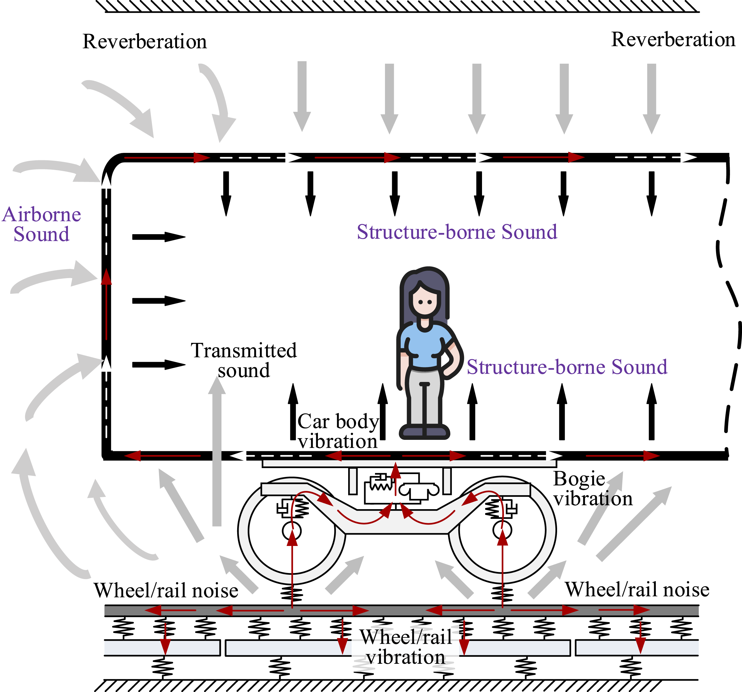
Engineering challenges in interior noise reduction encompass noise source identification and control measures (Thompson, 2008). Currently, the test-based structure-borne sound analysis mainly relies on Transfer Path Analysis (TPA) and its improved algorithms. Fan et al. (2014) identified the interior noise sources of high-speed trains using sound intensity and partial coherence. Zhang (2015) analyzed the measured results of interior noise of Beijing metro trains based on the OTPA method and studied the transfer paths of noise and vibration. Thompson et al. (2018) conducted the separation and evaluation of wheel and track contributions to railway rolling noise based on measurement methods combined with the TWINS model. Zhang et al. (2019) performed sound source localization on the 350 km/h high-speed train and analyzed the structure-borne and airborne sound transfer paths of the interior noise. Peng et al. (2022) established a vertical dynamic model of the coupled system consisting of the bogie, carbody, and car seat and used it to analyze the vehicle’s vibration response, ride comfort, and parameter sensitivity. Lan et al. (2025) studied the locations of main noise sources and energy distribution of 400 km/h high-speed trains in operation, established the correlation between vibration, noise, and speed, and quantified the noise contribution of each region as well as the overall influence of tunnel boundaries. To conduct a more in-depth analysis and understanding of structure-borne path transmission, it is usually necessary to combine it with numerical modeling and analysis. Li et al. (2021) proposed a computational framework based on the statistical energy method for predicting airborne noise (including rolling noise) inside railway vehicles. Zhang et al. (2023a, 2023b, 2024) conducted a preliminary study on the prediction of interior noise caused by wheel–rail rolling behavior in tunnels. Li et al. (2024) analyzed the vibroacoustic response and aerodynamic contribution characteristics of the extruded profile of high-speed trains under fluid-induced vibration using numerical methods. Wen et al. (2025) established a vertical dynamic model of the coupled system consisting of the bogie, carbody, and car seat based on the energy method and analyzed the vehicle’s vibration response, ride comfort, and sensitivity.
However, in previous literature, the severe crosstalk between paths in TPA-based methods has significantly affected the accuracy; meanwhile, in the numerical calculation of contribution analysis, there are slight deficiencies in the refined simulation of components, and the influence of reverberant environments has not been fully considered. Therefore, this paper intends to study the energy contribution characteristics of the multi-dimensional transmission of wheel–rail noise/vibration components into the vehicle interior under the tunnel reverberation environment, and explore the layered multi-dimensional transmission laws of wheel–rail rolling behavior and underframe mechanical forces. This is of great significance for proposing precise interior noise control strategies based on sound energy contribution separation in the later stage.
Bogie vibration transmission and interior noise prediction modeling
Vehicle dynamics model
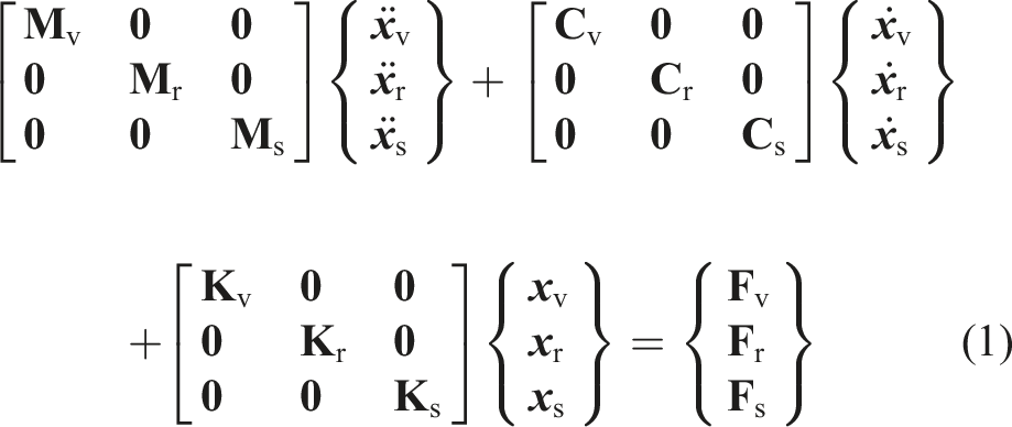
The train, rail, and floating slab serve as three subsystems coupled through wheel-rail interaction. The normal force is described using the Kik-Piotrowski multi-point contact model within the nonlinear Hertzian elastic contact theory, while the tangential force is calculated using the FASTSIM algorithm within Kalker’s linear creep theory. The following equation describes the resulting vehicle-rail-floating slab coupled system, and the basic parameters can be seen in our published paper (Zhai, 2020).
Co-simulation with UM-ANSYS-MATLAB implements this 35-DOF rigid-body vehicle model, comprising a car body, two bogies, and four wheelsets. Primary suspensions use visco-elastic damping, while secondary suspensions employ mechanical models and nonlinear air springs. The underframe connects multiple subsystems (secondary air springs, dampers, traction links, anti-yaw dampers, lateral stops, torsion bars). Rails are modeled as Timoshenko beams on linear spring-damper fasteners. Floating slabs use 3D solid elements, with steel springs simulated as linear spring-dampers connecting slabs to rigid tunnel foundations (non-vibrating ground), see Figure 2. Train-Rail-Slab coupling vibration model and the multi-components of bogie (1. Air spring; 2. Anti-snake shock absorber; 3. Anti-roll torsion bar spring; 4. Second series transverse shock absorber; 5. Traction rod; 6. Lateral stop; 7. Vertical shock absorber).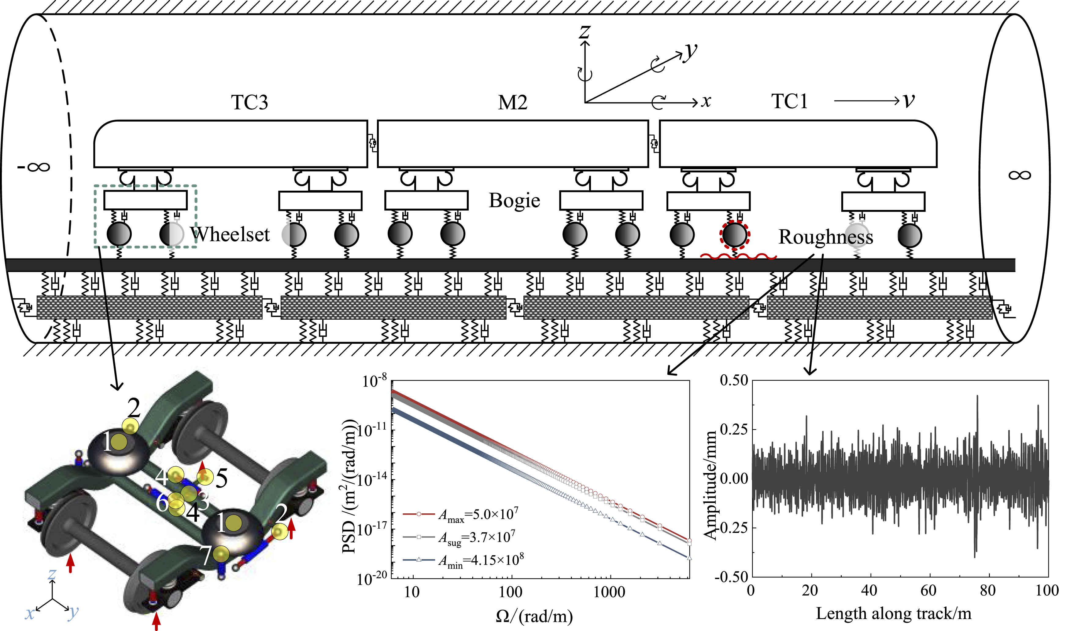
Key components include: I. Anti-roll torsion bar and lateral stop
The anti-roll torsion bar system (torsion bar, arms, vertical hangers) constrains car body roll through shaft-supported torsion. During body roll, differential hanger motion induces opposing forces on the torsion bar, generating torsional deformation (equivalent stiffness Krx = 2.5 × 10⁶ N·m/rad). Meanwhile, the lateral stop—featuring rubber elements with a free gap—provides nonlinear lateral stiffness (Kmy) when compressing the center-pin during curve negotiation. Both mechanisms are detailed in Figure 3. Lateral stop and anti-roll torsion bar equivalent model.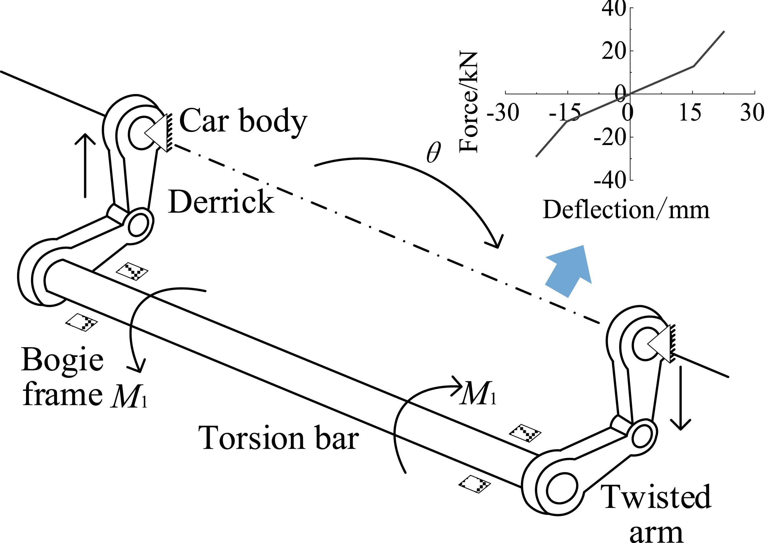
The anti-roll torsion bar and lateral stop are simulated using the bushing forces. Assuming two interacting bodies, for example, a lateral stop (body 1) and a car body (body 2), the relative coordinate positional relationship between the bushing and the bodies (coordinate alignment) is defined. There is an assumed force application point B on body 1 for body 2 and point A on body 2 for body 1. The relative positions of the force application points and the hinge points are describable by spatial vector coordinates (distance, angle). II. Traction link
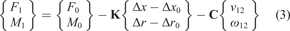
The traction link is described using the linear model within the bipolar forces. The bipolar forces connect selected fixed points on the frame (object 1) and the car body (object 2), as shown in Figure 4. Traction link equivalent model.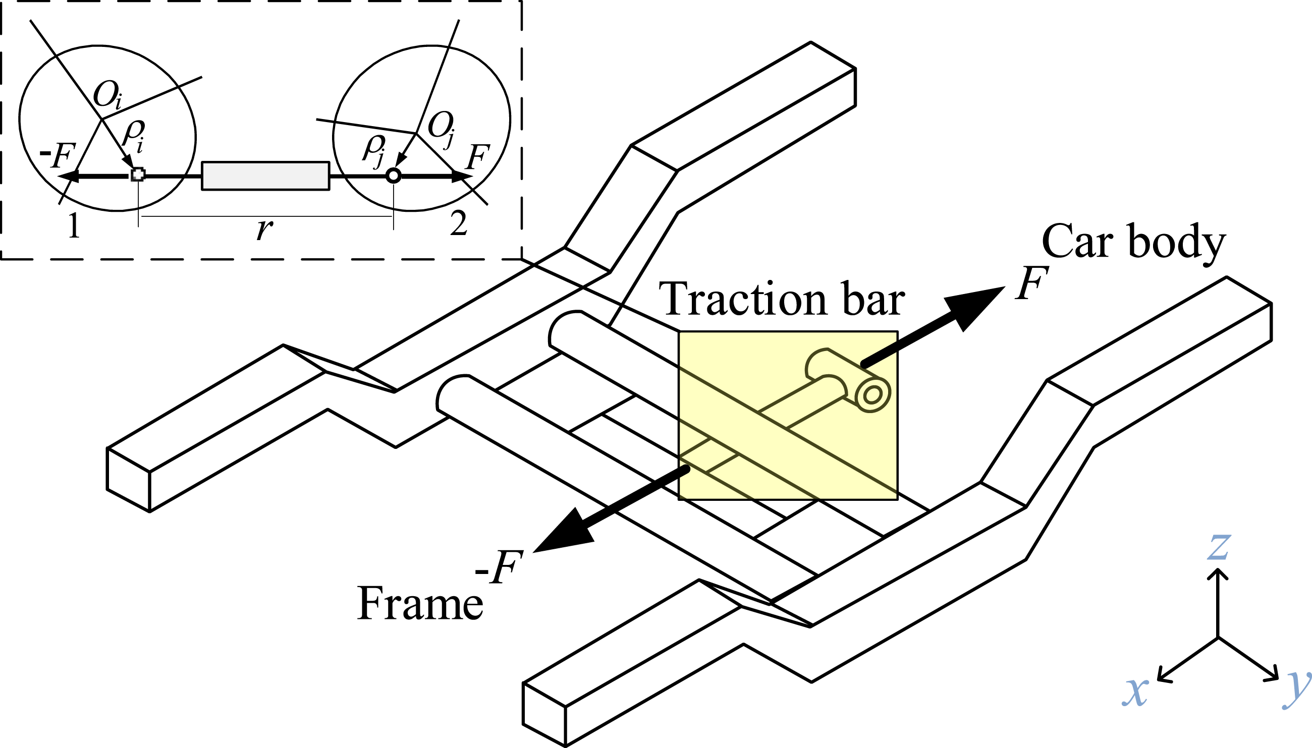
The force acts along the straight line between two points and depends on time t, the distance r between them, and its derivative r′ with respect to time, that is, F = F (t, r, r′). The model is used to simulate linear visco-elastic interactions with harmonic excitation: III. Anti-yaw dampers and vertical dampers

The dampers are series-connected nonlinear visco-elastic systems (a nonlinear spring and damper in series). The nonlinear characteristics are described by deflection-elastic or velocity-damping curves. The nonlinearity must be a strongly monotonically increasing function passing through the origin. Linear fitting and numerical extrapolation are applied to assign values beyond predefined sections, as shown in Figure 5. A series of nonlinear visco-elastic models.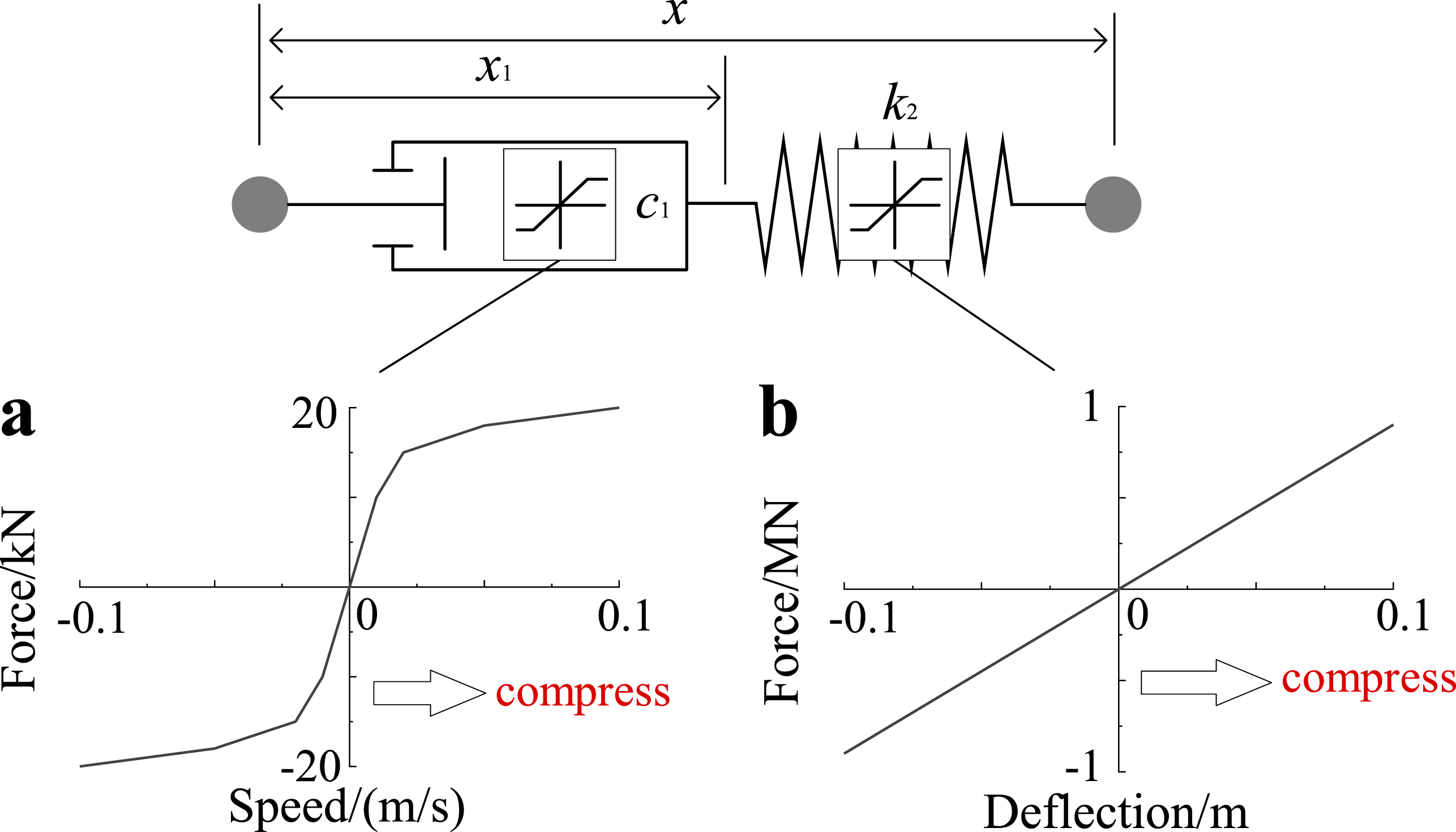
Incorporating Figure 5, the model introduces a new variable x1 and an ordinary differential equation implicitly expressed as F ( ). The differential equation description of the series nonlinear visco-elastic model is then formulated as: IV. Secondary lateral damper


The secondary lateral vibration damper adopts a parallel linear visco-elastic model (spring-spring/damper). It consists of a damping/spring element in parallel connection, followed by a series connection with a second spring. The differential equation of the parallel linear visco-elastic model is: V. Air spring

The vertical characteristics of air springs exhibit a complex nonlinear relationship with their structural parameters, enabling a more precise description of the filtering characteristics of the primary and secondary suspensions against vibrations originating from the wheel–rail interface. Figure 6 depicts a schematic diagram of the thermodynamic model for a nonlinear spring featuring two parallel air bladders connected by an orifice. Thermodynamic model of a nonlinear air spring.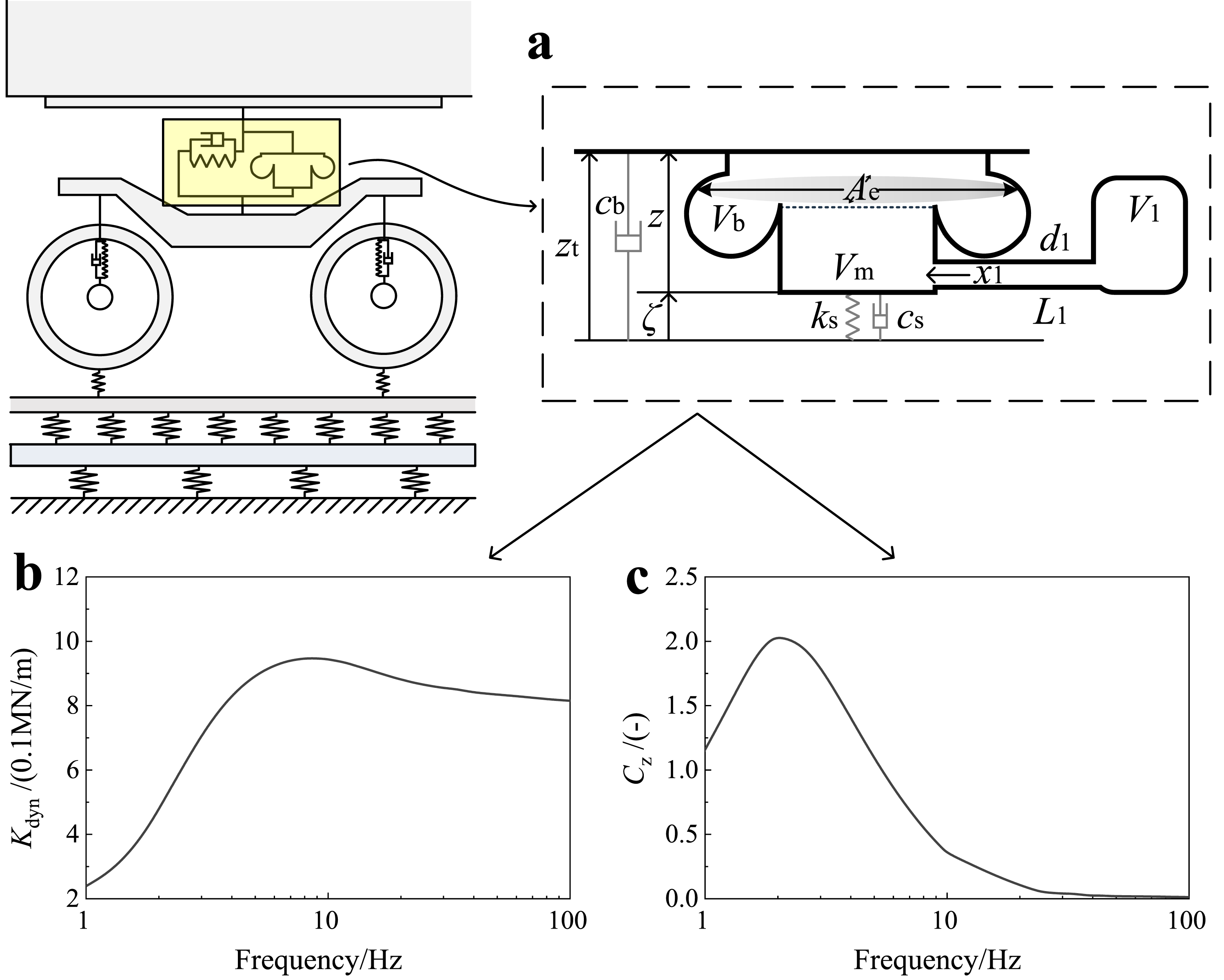
Parameters of nonlinear air spring.
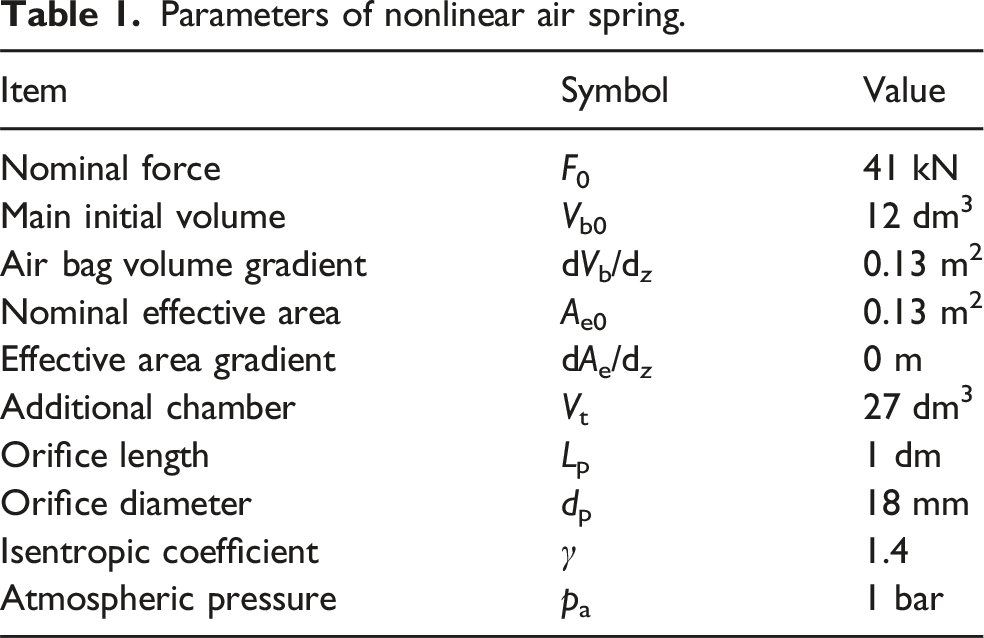
After simulating the air spring’s upper and lower constraints, a unit vertical sinusoidal excitation force F (ω) = sin (ωt + φ) is applied to its cover plate. By inputting sinusoidal excitations of different frequencies (frequency sweep), the dynamic response and stiffness at the corresponding frequencies can be obtained. Due to the friction-damping effect of the gas flowing through the orifice, the force–-displacement relationship exhibits an elliptical variation. Based on the hysteresis curve’s elliptical geometric characteristics, the vertical stiffness Kdyn and damping coefficient Cz can be calculated.
Frequency-division prediction model for interior noise in a tunnel
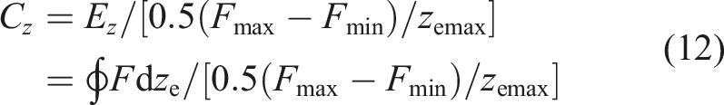
Sound field reconstruction for tunnel-vehicle systems faces methodological challenges: BEM, hybrid, and SEA techniques each exhibit specific applicability and limitations requiring further research. Accurate modeling demands appropriate methods with problem-specific adaptations. Composite body structures present particular difficulties due to material complexity and structural details – their effective integration into acoustic models remains critical. The solution implements a frequency-division framework (Figure 7), deploying SEA, H-hybrid, and BEM methods across frequency bands to achieve comprehensive sound field reconstruction. Interior noise models: (a) high-frequency (315∼1000 Hz); (b) medium-frequency (100∼315 Hz); (c) low-frequency (20∼100 Hz).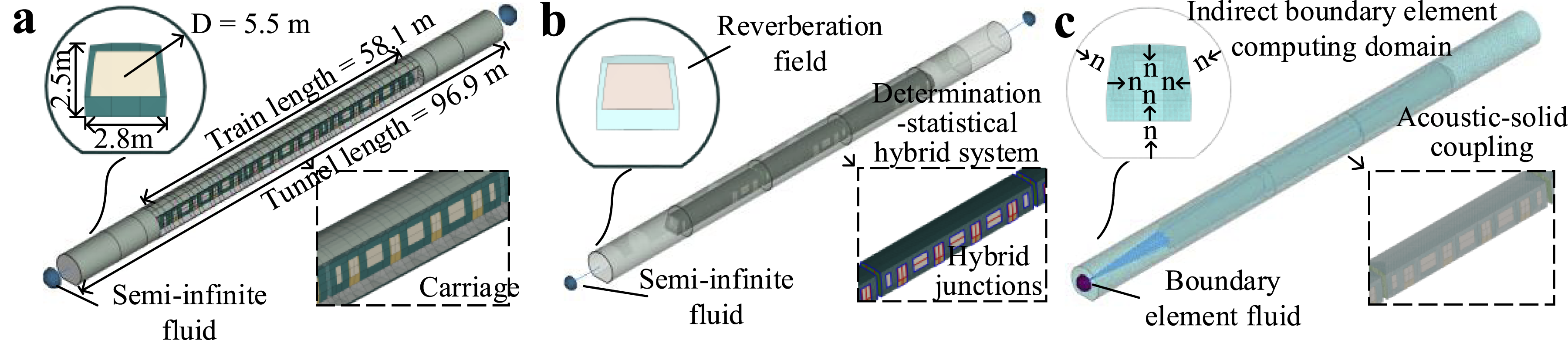
In these models, the car body adopts a type-B vehicle and three-car formation (towing + powered + towing). Each of the three cars has four passenger compartment doors. The head/tail car also contains the driver’s cab and side/back doors, with a total length of 58.1 m. The tunnel inner diameter is set to 5.5 m, and the tunnel length is set to the total length of a five-car formation, that is, 96.9 m.
Sound field modeling employs a tri-band approach. High-frequency: weak-coupling SEA establishes the base model with subsystem division and equivalent processing (body/windows). Virtual insulation tests validate performance (Wu et al., 2022); tunnel/train reverberation tests refine parameters. Body updates enable full high-frequency sub-model construction. Mid-frequency: wave-coupling-based H-hybrid model treats the body deterministically (discretized structure) and other components statistically. Low-frequency: sound-structure coupling defines vehicle/tunnel boundaries for indirect BEM sub-model development. This prediction framework enables acoustic analysis and noise control.
Wheel/rail rolling noise prediction
Noise evaluation requires three integrated modules: wheel-rail interaction, rolling sound radiation, and trackside sound pressure averaging to analyze acoustic-vibration coupling and boundary effects for comprehensive sound power/pressure assessment (Ahn et al., 2019; Thompson, 2008; Zhang et al., 2024). Wheel–rail force calculation (Figure 8) applies Hertz contact theory with moving roughness excitation through the wheel–rail gap. This frequency-domain model incorporates roughness, contact filtering, and wheel/rail/slab admittance. Sound power analysis combines structural vibration theory with rail attenuation and component radiation efficiency to quantify rolling noise power spectra and achieve source separation (wheel/rail/slab). Trackside sound pressure uses virtual source modeling (rectangular tunnel), treating components as: wheels (oscillating spherical sources), rails/slabs (oscillating/pulsating cylindrical sources) to compute time-space averaged pressures. Wheel/rail rolling noise: (a) rail/wheel/contact mobility; (b) fitted radiation efficiency; (c) sound radiation power.
Vibration transmission of the vehicle system
Input separation of multi-dimensional vibration excitation
The vehicle runs along at a constant velocity of 60 km/h. The trend term is removed (removing the DC offset), and only the dynamic force (product of mass and acceleration) is retained. The result after time/frequency conversion of the obtained force/torque time-domain information is shown in Figure 9. Multi-dimensional vibration (narrow-band): (a and b) time/frequency analysis of anti-roll torsion bar; (c and d) time/frequency analysis of lateral stop; (e and f) time/frequency analysis of traction link; (g and h) time/frequency analysis of vertical damper; (i and j) time/frequency analysis of anti-yaw damper; (k and l) time/frequency analysis of lateral damper; (m and n) time/frequency analysis of air spring.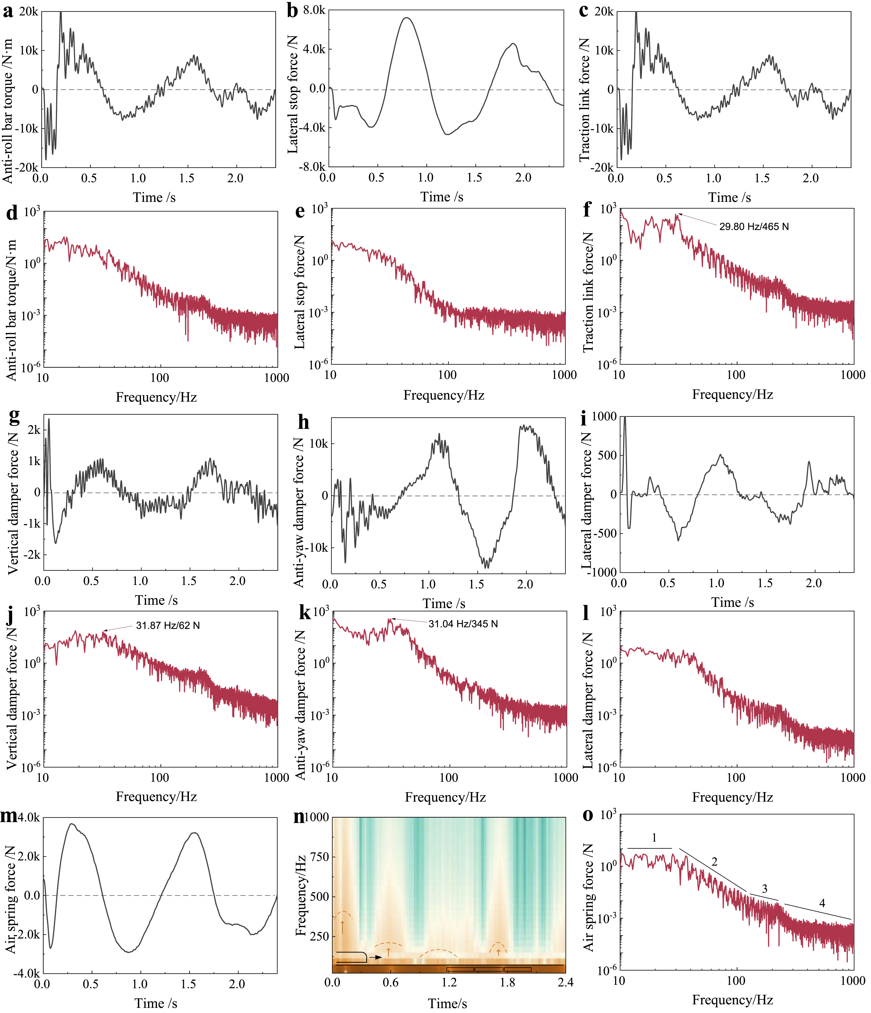
In Figure 9(b)/(d), for noise frequencies above 20 Hz, the anti-roll torsion bar and lateral stop show rapid amplitude decay. Given the slow subway speed, the spectral amplitude shifts left compared to high-speed trains at 300∼350 km/h. In Figure 9(f), for the traction link, during vehicle movement over floating plates and at calculation start, the car body–bogie relative displacement leads to high-frequency component amplitudes. It has a much larger overall amplitude than the lateral stop, with significant amplitudes in 20∼30 Hz contributing to low-frequency noise. In Figure 9(h)/(j), for vertical and anti-yaw dampers with the vehicle’s upper/lower floating plate, the car body–bogie relative motion causes large high-frequency amplitudes. The force spectrum shows considerable amplitudes in 20∼100 Hz, being an important low-frequency noise source (≤100 Hz). In Figure 9(l), the lateral damper has small amplitudes across frequencies, and after 10 Hz, the amplitude drops rapidly to nearly 1 N. In Figure 9(n), for the air spring, the force frequency spectrum shows rapid vertical dynamic force decay in the 1∼4 envelopes, the fastest among secondary suspension components. Mid-to-high frequency information amplitudes are minimal, reflecting its high-frequency filtering. As the primary support, it ensures ride comfort but is not a major interior noise contributor.
Based on train–track interaction theory, this study models vibrations of underframe components (load-bearing members and nonlinear suspensions). It clarifies the approach to get full-frequency mechanical force excitations and separates vibration inputs. Analyses of components (air springs, dampers, etc.) are done for separating vibration input contributions (converted to 1/3 octave, Figure 10). Below 60 Hz, anti-yaw dampers and traction bars are the main sources; 60∼1000 Hz, secondary vertical dampers are the most significant source. This lays the foundation for noise source separation and control. Multi-component dynamic input separation (1/3 octave).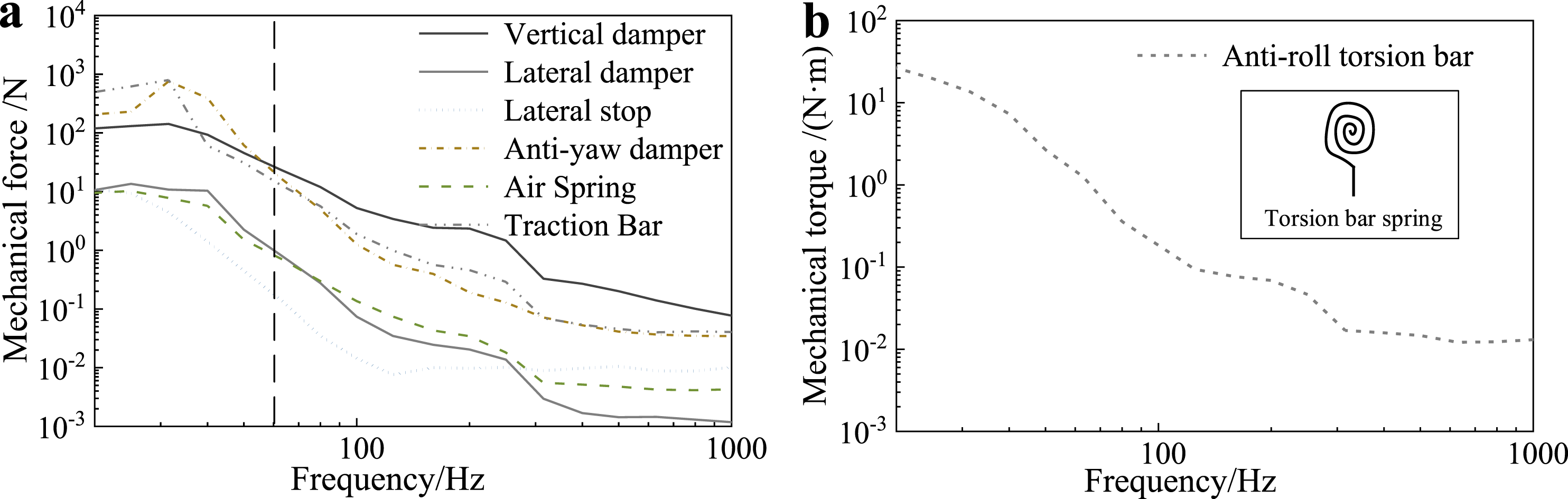
Transmissibility of the vehicle system
The vibrations of the multi-rod/suspension components of the vehicle underframe originate from the wheel–rail dynamic forces, and the vibration signals are closely related to the roughness of the wheels and rails. The transmission path of the vehicle underbody vibration is that the vibration generated by the wheel–rail rolling is transmitted layer by layer to the vehicle underframe through the primary and secondary suspension systems and then input to the floor, exciting the car body vibration and finally radiating noise (Cheng et al., 2020). According to the first estimation formula of frequency response, one form of expression of frequency domain transfer rate H (f) is the ratio of the cross-spectrum G
xy
(f) of the output signal and the input signal to the self-spectrum G
xx
(f) of the input signal. Transmissibility calculation of the vehicle system.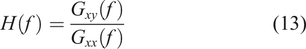
For this transmission process, the vibration transmissibility from the axle-box to the bogie frame and from the bogie frame to the car body is mainly investigated. In this section, emphasis is placed on the acceleration transmissibility, as shown in Figure 12. On the axle box to bogie frame transfer path: vertical amplification band is 3∼8 Hz; lateral is 8∼15 Hz; 2∼6 Hz has bogie frame heave mode; 1∼10 Hz has vehicle system lateral translation and body-bogie frame coupled roll mode. On the path from the frame to the car body: vertical vibration amplification band is 0.5∼1 Hz; lateral is 1∼2 Hz. From vehicle modal analysis, the former includes body heave, roll, pitch modes; the latter has the same body modes and body-bogie frame coupled roll mode. The body pitch/heave modes impact the vertical transmission of suspension components, and the roll mode affects the lateral. Comparing primary and secondary suspension transfer functions: Secondary suspension damping is better than primary. Vertical damping is better than lateral, and lateral high-frequency vibration attenuation is weak. For the transfer rate from the axle box directly to the car body, it is comprehensively determined by the hierarchical characteristics. Similar to a series spring system, the transfer rate basically approaches the side with a lower value. Since the flexible effects of the wheel set and the bogie frame have not been considered yet, the transfer characteristic curve fails to well reflect the influence of the participation of the multi-order bending and elastic modes of the wheel. Transmissibility of vehicle system: (a and b) vertical and lateral transmissibility from axle-box to bogie frame; (c and d) vertical and lateral transmissibility from bogie frame to car body; (e and f) vertical and lateral transmissibility from axle-box to car body; (g) primary spring to secondary vertical damper; (h) primary spring to secondary air spring; (i) primary spring to secondary lateral damper; (j) primary spring to lateral stop.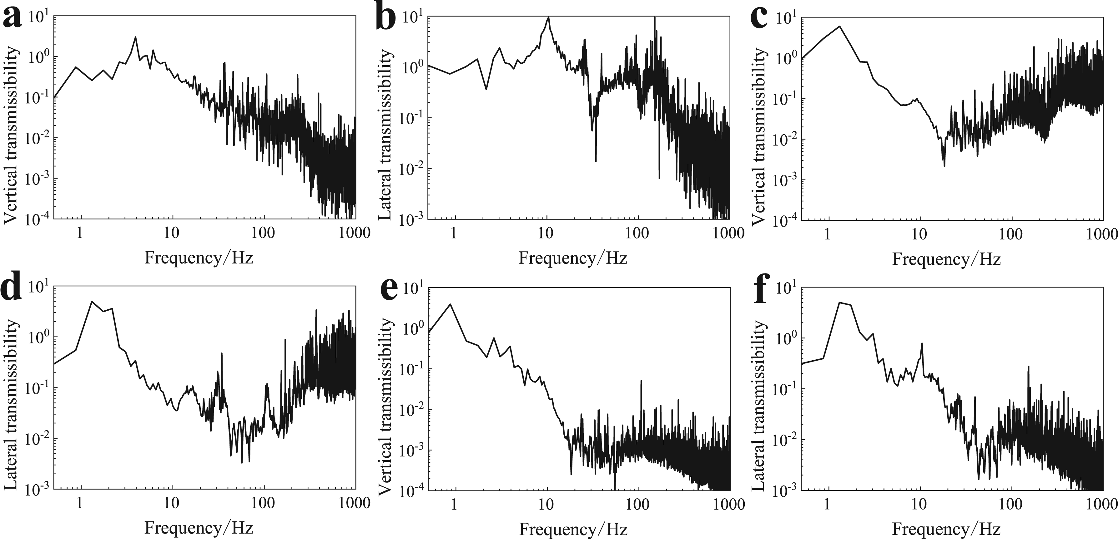
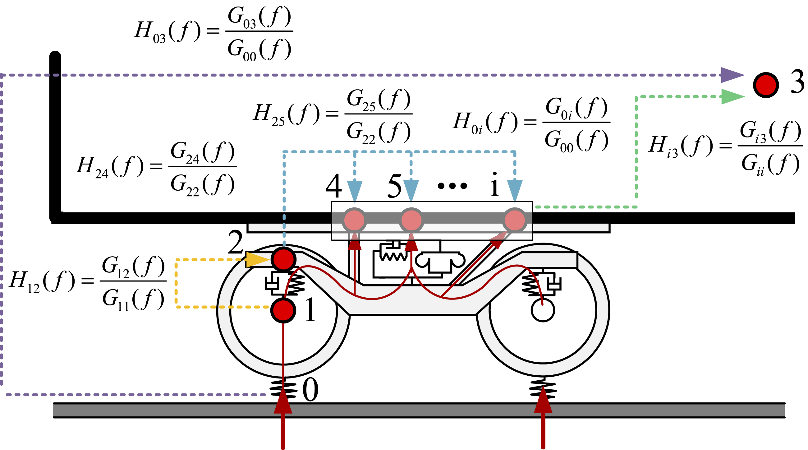
Now, the layered transmissibility is defined as the square root of the ratio of the summed spectrum of responses from the vibration environment response point group to the summed spectrum of responses from the reference vibration environment point group. The vertical and lateral force transmissibility among multiple components from the primary system to the secondary system has been investigated, as shown in Figure 13. Based on the summarized spectra of the axle box, frame, and car body, the hierarchical transmittances of the primary suspension (Tpri (f)) and secondary suspension (Tsec (f)) are derived as follows: Layered transmissibility of bogie system: (a) primary vertical; (b) primary horizontal; (c) secondary vertical; (d) secondary horizontal.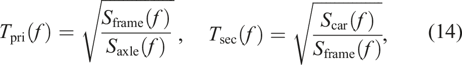

For the calculation between primary and secondary suspensions, it is the force transfer rate. Due to the existence of damping, there is almost no method area in the vertical direction. And it can be clearly seen that the air spring has a low transfer rate at high frequencies, which means that it can isolate the transmission of high-frequency vibrations better than the vertical shock absorber, and more high-frequency components are filtered. In the lateral force transfer rate, the secondary lateral shock absorber still maintains a relatively high transfer rate in the low-frequency range of 5–25 Hz. Due to its large stiffness, the lateral stop also maintains a relatively large transfer rate in the range of 5–30 Hz. This means that if in a curved track condition, then the components mainly with lateral total force will definitely contribute much more to the interior noise than under the current straight-line operation.
Separation of contributions from vibration transmission to interior noise
Contributions to the separation of structure-borne and airborne-borne path
Using the frequency-division integrated prediction model for tunnel-vehicle sound fields, the mechanical force excitation, the wheel–rail rolling sound excitation, and their combined effects were loaded. A-weighted results are selected due to common engineering practices and their consistency with human auditory perception, while linear results are retained to reflect physical characteristics more accurately and serve as a reference for energy contribution ratio analysis, as shown in Figure 14. Contributions separation of structure-borne and airborne-borne path: (a and c) standing position 1 at the coach end; (b and d) sitting position 5 in the coach middle; (e and f) energy proportion of position 1 and 5 (where ARB: anti-roll torsion bar; SLD: secondary lateral damper; AYD: anti-yaw dampers; ASP: secondary air spring; SVD: secondary vertical damper; TL: traction link).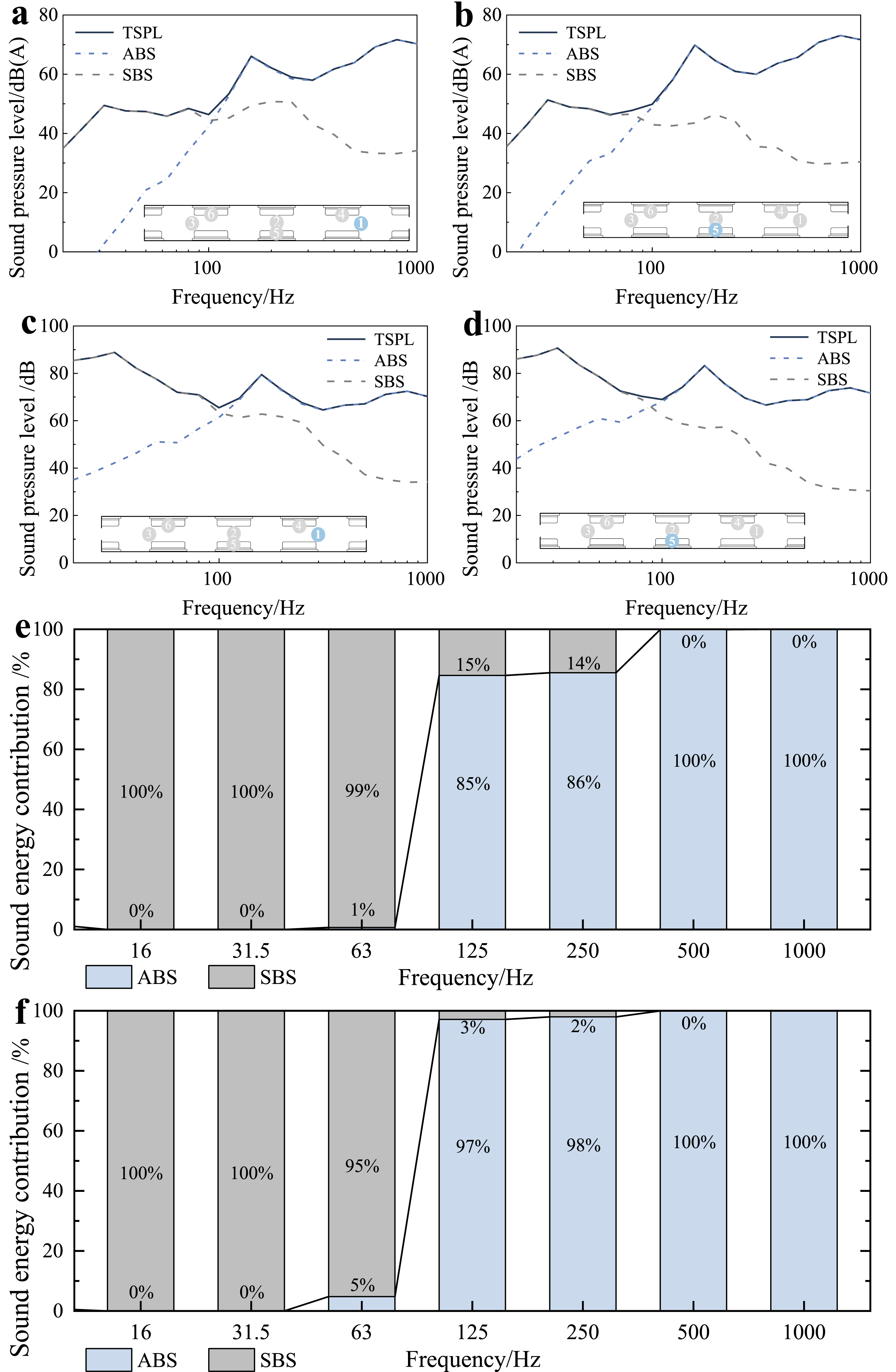
The Acoustic responses and sound energy results under corresponding excitations were calculated for both structural and airborne sound paths to clarify the relative contributions of these two paths to the total noise. Typical analysis points were selected at the end of the carriage near the bogie (standing position 1) and in the middle of the carriage near the door (sitting position 5), as shown in Figure 14. For speech perception and understanding, the frequency ranges of 500∼2000 Hz are particularly important, and the sound excitation of the air path is undoubtedly the most important noise source, which should be given priority control.
Contribution to the separation of the multi-dimensional vibration
The vibrations generated by wheel/rail rolling are transmitted to the floor through the primary suspension, frame, and secondary suspension, exciting structural noise in the car body. The vibrations of multiple components in the car underframe originate from wheel–rail dynamic forces. Proper separation of the contributions of multiple components in the structural sound path is crucial for low-frequency noise control. Utilizing a comprehensive predictive model for frequency division of the tunnel-vehicle sound field, we loaded the mechanical force excitation ensemble at the vehicle bottom and individual component forces. Typical analysis and measurement points were selected as the end of the carriage near the bogie (position 1) and the middle of the carriage near the door (position 5). The component decomposition response and sound energy ratio results were calculated, as shown in Figure 15. Contribution separation of the multi-dimensional vibration: (a and c) standing position 1 at the coach end; (b and d) sitting position 5 in the coach middle; (e and f) energy proportion of positions 1 and 5 (where ARB: anti-roll torsion bar; SLD: secondary lateral damper; AYD: anti-yaw dampers; ASP: secondary air spring; SVD: secondary vertical damper; TL: traction link).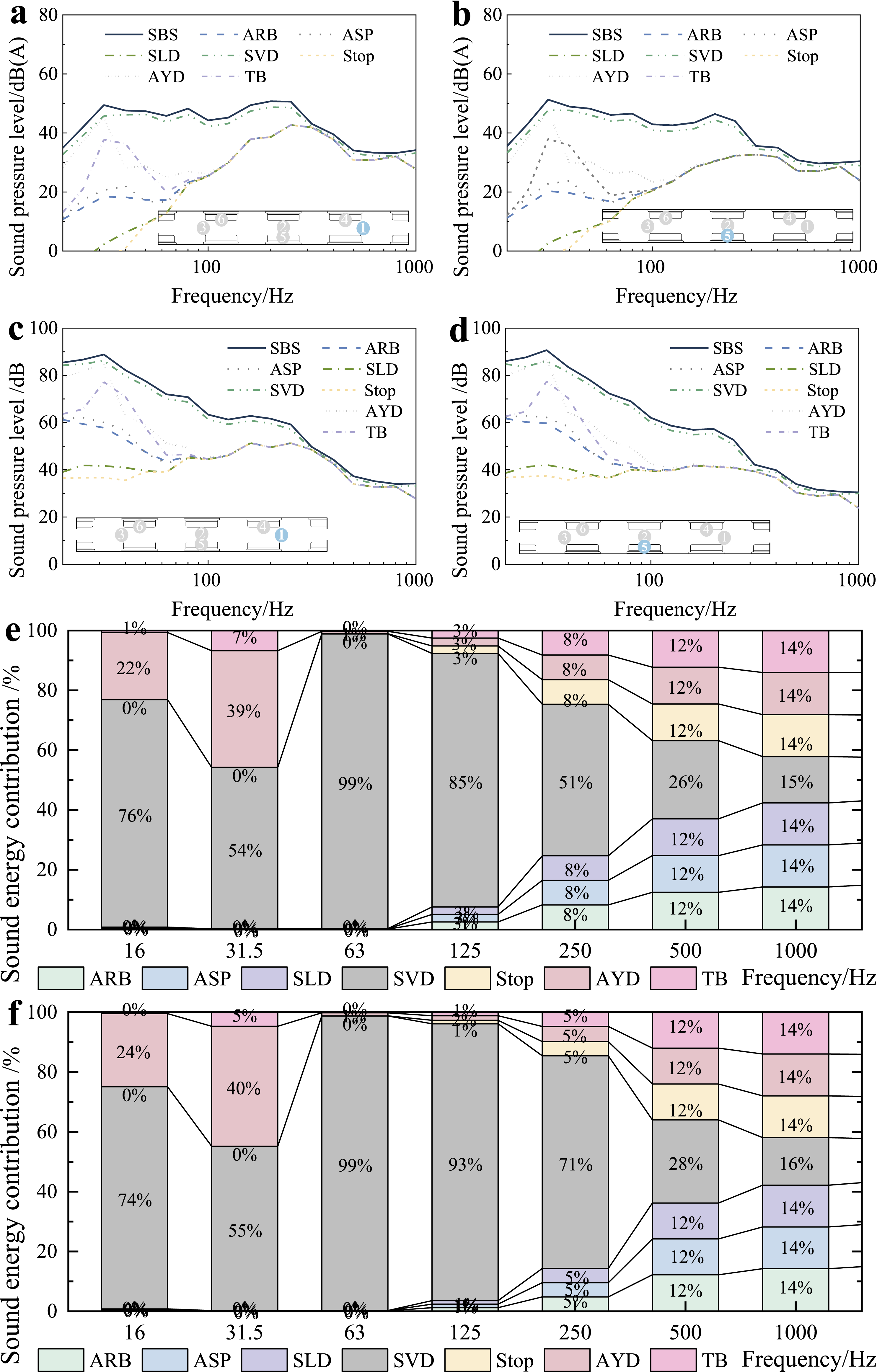
By analyzing the separation results of the multi-component vibration contributions, the following conclusions can be drawn: Below 250 Hz, there are significant differences in the contributions of different components to the vibration spectrum; whereas in higher frequency ranges, the vibration spectrum distribution tends to converge, with each component contributing approximately 14%. Among these components, although the air spring bears most of the vehicle’s mass, its nonlinear characteristics in the airbag enable it to filter out high-frequency vibrations. The secondary vertical damper, a key component connecting the frame and underframe (car body), does not exhibit prominent vibration filtering capabilities due to its hydraulic mechanism, resulting in the retention of more high-frequency components. Consequently, it becomes the dominant factor contributing to sound energy within the 16–250 Hz frequency range, with an energy contribution of 55%∼99%. Clearly, within this frequency range, the secondary vertical damper is the primary vibration contributor. Additionally, the anti-yaw damper significantly contributes to vibrations within the 16∼40 Hz range, with an energy contribution of 24%∼40%.
Conclusion
The following conclusions have been obtained from the study: (1) For integrated dynamics modeling, a high-fidelity vibration model of underframe load-bearing rods and nonlinear suspensions, including air springs, secondary vertical/lateral dampers, traction rods, anti-yaw dampers, lateral stops, and anti-roll torsion bars, was established by integrating train-track dynamic interaction theory with multi-body dynamics and finite element methods FEM. This modeling framework has laid a solid foundation for analyzing the contribution of sound sources to interior noise. (2) For vibration transfer analysis, below 60 Hz, anti-yaw dampers and traction rods dominate vibration inputs. Between 60 and 5000 Hz, secondary vertical dampers are the primary source. Transfer path analysis confirms hierarchical amplification of vertical vibrations 3–8 Hz axle→bogie; 0.5–1 Hz bogie→body, and lateral vibrations 8–15 Hz axle→bogie; 1–2 Hz bogie→body are governed by body heave/pitch and roll modes. The secondary suspension exhibits superior damping, with air springs isolating vibrations above 25 Hz, while lateral components dampers/stops show strong transmissibility at 5–30 Hz. (3) For noise path contributions, the priority of noise control is sorted as follows, to align with the research objective (precision noise control). Sound path control priority: The airborne sound path is identified as the top-priority control object for speech perception and understanding (key frequency range: 500∼2000 Hz). Its sound excitation is the most critical noise source and should be prioritized in engineering implementation. Component control priority by frequency range: 16∼250 Hz: The secondary vertical damper is the primary control component, contributing 55%∼99% of the sound energy. Its hydraulic mechanism retains more high-frequency vibrations, making it the dominant vibration contributor in this range. 16∼40 Hz: The anti-yaw damper is a secondary priority component, with an energy contribution of 24%∼40% that requires targeted control. Above 250 Hz: Vibration contributions of each component converge (≈14% per component), and the air spring’s nonlinear characteristics filter high-frequency vibrations, so no single component needs prioritized control—focus should shift to the airborne sound path.
The current component contribution analysis has only accounted for straight-line operating conditions, resulting in an unclear characterization of lateral excitation contributions. Future efforts will consider a broader range of operating conditions. Additionally, the mechanical forces at the vehicle’s bottom are primarily based on time-domain linear models, which significantly limit the accuracy of predicting high-frequency vibration transmission in rod components. Addressing these two aspects will be the focus of the next phase of work.
Footnotes
Funding
The authors disclosed receipt of the following financial support for the research, authorship, and/or publication of this article: This work was supported by the National Natural Science Foundation of China (52505140), the Natural Science Foundation of Chongqing Municipality (CSTB2025NSCQ-GPX0127), the Science and Technology Research Program of Chongqing Municipal Education Commission (KJQN202500822), the Chongqing Key Laboratory of Urban Rail Transit System Integration and Control Open Fund (CKLURTSIC-KFKT-24001), and the Scientific Research Startup Project for High-level Introduced Talents at Chongqing Technology and Business University (2456012).
Declaration of conflicting interests
The authors declared no potential conflicts of interest with respect to the research, authorship, and/or publication of this article.