
Abstract
The 600 km/h high-speed maglev transportation system represents the fastest existing ground transportation technology. As the electromagnetic suspension (EMS) type high-speed maglev system currently lacks the conditions for full-speed testing, this study conducted low-speed dynamic experiments to investigate the vibration transmission characteristics within the vehicle system. First, time-domain track irregularity data were derived from the low-speed experimental data. Subsequently, time-frequency analysis was performed on the dynamic responses at different vehicle locations, and the coherence between track irregularities and these responses was investigated. Finally, the vibration transmission characteristics were analyzed using the vibration acceleration level difference method. The results indicate that the energy of the measured track irregularities is concentrated within the low-frequency range below 15 Hz. Within the 0∼13.67 Hz low-frequency range, track irregularities constitute the primary influencing factor on the vehicle’s dynamic responses. The vibration reduction performance of the primary suspension is relatively weak. In contrast, the flexible levitation frame and air spring exhibit frequency-dependent vibration reduction effectiveness across different bands, while the bolster, hanger rod, and auxiliary floor demonstrate effective vibration isolation and reduction performance across the entire frequency range. These findings provide support for the optimization of suspension systems in high-speed maglev vehicles.
Keywords
Introduction
The high-speed electromagnetic suspension (EMS) maglev system exhibits significant advantages including high-speed potential, strong curve negotiation capability, excellent gradient-climbing ability, and low noise levels, making it a prominent research focus in rail transit in recent years (Shi et al., 2022). Although China has developed a 600 km/h maglev prototype, dedicated tracks for such speeds remain unbuilt (Ding et al., 2023). These systems maintain stable levitation by dynamically adjusting electromagnetic forces between onboard magnets and ferromagnetic tracks to counteract gravity and external disturbances (Xiang et al., 2022; Zhang et al., 2022). Track irregularities directly affect the levitation gap and electromagnetic force, while fluctuating electromagnetic forces alter the vibration state and displacement of the flexible track, thereby generating new excitation sources. Consequently, EMS maglev systems exhibit pronounced vehicle-track coupled vibration effects (Huang et al., 2018; Wang et al., 2019a). Coupled vibrations between onboard electromagnets and the track propagate through the primary suspension, levitation frame, air spring, bolster, and rod to the carbody, ultimately impacting ride comfort. Thus, investigating vibration transmission patterns in high-speed maglev systems is critical for suppressing vehicle-track coupled vibrations and advancing the technology toward practical implementation.
Due to the existence of only one commercial high-speed maglev line, research on the vehicle-track coupled vibration problem of EMS-type high-speed maglev trains has long relied primarily on multi-physics simulation methods. After decades of continuous research, high-speed maglev dynamics simulation methods have matured significantly, evolving from early single-degree-of-freedom models (Ren et al., 2010) to multi-degree-of-freedom spring-damper models (Wang et al., 2019b), and further to vehicle-magnetic-track multi-physics coupling dynamics models (Feng et al., 2022, 2025). Simulation studies have mainly focused on three aspects: the control subsystem, the vehicle subsystem, and the track subsystem. Gottzein et al. (1980) investigated the relationship between vehicle dynamic performance and control parameters. Studies indicate that under stationary and low-speed conditions, dynamic performance primarily depends on control parameters. However, at high speeds, the situation becomes more complex due to vehicle-track coupling effects. Sinha et al. (2002) examined differences in system stability under various control parameters. Feng et al. (2023) and Sun et al. (2022) studied the impact of levitation feedback time delay on dynamic characteristics. Feng et al. (2021) investigated the influence of bolster-hanger length on the dynamic performance of high-speed EMS maglev vehicles. Zhao and Zhai (2002) attempted to address vehicle-track resonance issues through optimization studies of maglev train system dynamics parameters. Han et al. (2009) researched the relationship between track beam frequency and the vibration frequency of the coupled system. Yu et al. (2021) established a 10-degree-of-freedom vehicle and guideway model to investigate the stochastic vibration characteristics of high-speed maglev systems. Zhang and Yu (2025) developed a three-dimensional vehicle-guideway coupled system to study the random dynamic response of high-speed maglev systems. These modeling and simulation studies are of great significance for advancing the engineering application of high-speed maglev technology. Nevertheless, for high-speed maglev technology to reach full maturity, long-term experimental validation remains essential.
In recent years, related research on test benches and experimental lines has also been reported. Ding et al. (2023) established a vibration test bench for the high-speed maglev vehicle running system, which can validate the performance of high-speed maglev prototypes through hybrid testing method. The main high-speed maglev test lines include the Emsland test line in Germany (Bohn and Steinmetz, 2003) and the Tongji University test line in China (Li et al., 2016; Zhang and Huang, 2019). These test lines can only conduct low-speed experiments and are unable to achieve full-speed testing at 600 km/h. Jiang et al. (2023) and He et al. (2022) conducted detection of track defects and joint conditions, while Shi et al. (2014) and Liu et al. (2023) collected measured gap data and electromagnetic acceleration data from high-speed maglev systems, investigating the characteristics of track irregularities and its impact on vehicle dynamics. Li et al. (2020) utilized field-measured data to validate dynamic models. Given the current absence of testing conditions to achieve the design speed for the new 600 km/h prototype vehicle, analysis of low-speed experimental data offers a viable approach to investigate the coupled vibration transmission characteristics of the high-speed maglev system. Insights gained under low-speed conditions can provide a valuable reference for future in-depth research on vehicle-guideway dynamic responses at higher speeds.
In this study, time-domain track irregularities were first derived from low-speed experimental data. Subsequently, the time-frequency analysis was performed on the dynamic response at different locations of the vehicle. The coherence between track irregularities and vehicle dynamic response was investigated. Finally, the vibration transmission characteristics of the vehicle were studied based on the vibration acceleration level difference method. The main contributions of this study are as follows: (1) Based on low-speed experiments, this study conducts an in-depth analysis of the time-frequency characteristics of the dynamic responses of the 600 km/h vehicle and constructs levitation and guidance irregularity data from measured data, thereby providing data support for refined modeling of the high-speed maglev system. It should be noted that this paper does not involve simulation analysis of high-speed maglev vehicle-electromagnetic-guideway coupled dynamics. (2) Through time-frequency analysis and coherence analysis, this study found that within the low-frequency range of 0∼13.67 Hz, measured track irregularities is the primary influencing factor on vehicle dynamic responses. This finding offers important references for establishing track’s technical standards for future 600 km/h lines. (3) Utilizing the vibration acceleration level difference method, the acceleration responses at different vehicle locations are analyzed, and the vibration reduction performance of key suspension components is quantitatively evaluated. These results offer significant reference value for optimizing the parameters of the suspension system in future 600 km/h prototype vehicles.
Experimental setup
Experimental line and experimental vehicle
The 1.5 km high-speed maglev experimental line is located at the Jiading Campus of Tongji University, China. It provides an experimental environment with one train, five sections, and double-end power supply. Figure 1 shows the layout of the experimental line, which includes a parking maintenance depot, a set of low-speed switches, low-lying straight sections, a small curve with 400 m radius, elevated straight sections, curves with 1300 m and 1000 m radii, and other sections, totaling approximately 1.5 km in length. The bridges primarily consist of simply supported beams with spans of 12.384 m, 18.576 m, and a small number of 24.872 m. Due to length constraints of the test line, high-speed testing is not feasible, permitting only low-speed functional verification. The maximum speed achieved during testing was 50 km/h. Under such low-speed conditions, comparing performance variations across different speeds holds limited significance. Therefore, this study systematically analyzes data obtained from the 40 km/h steady-state condition. The corresponding test line section includes segments from a straight section to a curved section with a radius of 400 m, with guideway beam spans of 12.384 m and 18.569 m. The high-speed maglev experimental line.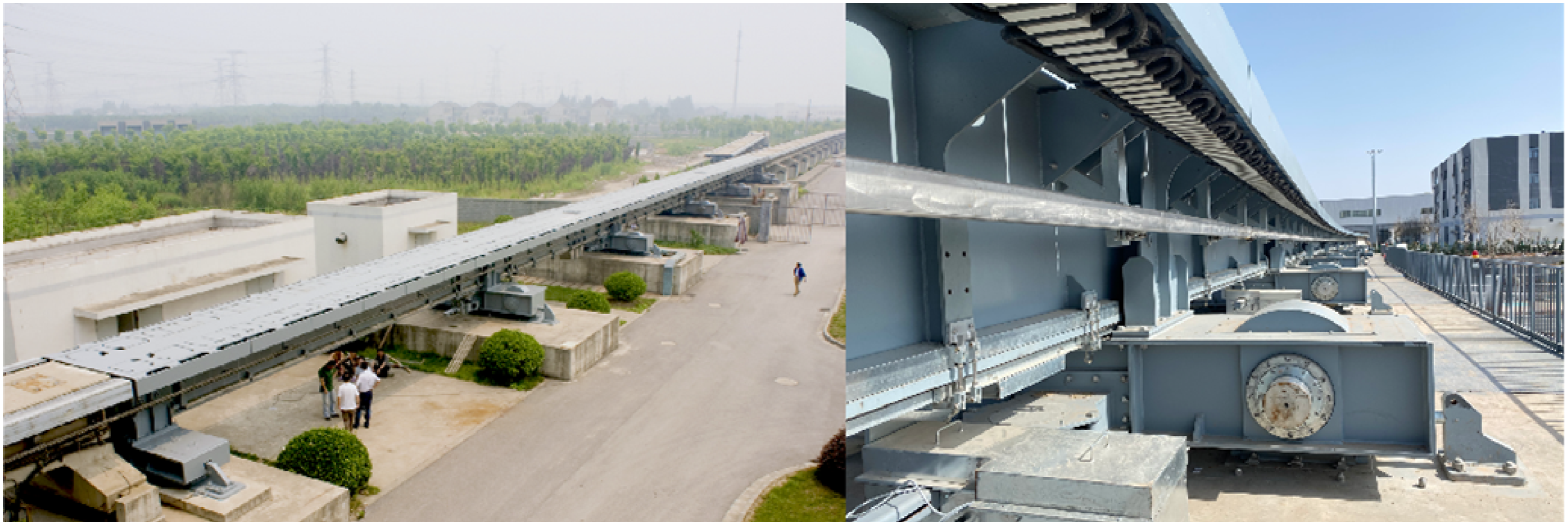
The experimental vehicle is a 600 km/h high-speed maglev prototype vehicle developed by CRRC Changchun Railway Vehicles Co., Ltd. It is a single-car vehicle, approximately 27.8 m long, propelled by a ground-side long stator synchronous linear motor. Four levitation frames are installed beneath the vehicle. Both the left and right sides of each levitation frame module are equipped with levitation electromagnets and guidance electromagnets. Adjacent levitation frames feature overlapping levitation and guidance magnets. At the middle section of the vehicle, between the No. 2 and No. 3 levitation frames, non-overlapping guidance electromagnets are replaced by eddy current brake magnets, which provide emergency braking force for the vehicle.
Vehicle measurement scheme
Test devices.
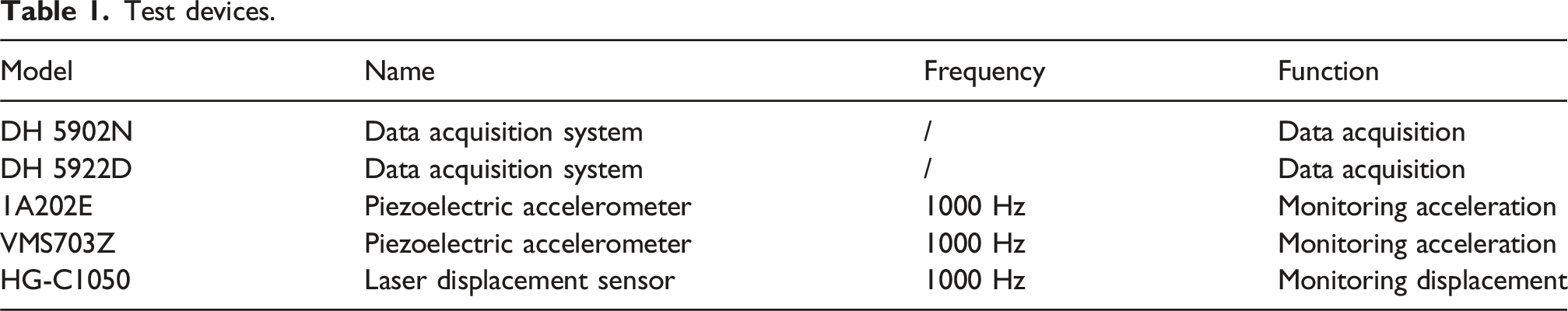
Given that the technical configurations of the four levitation frames are largely identical, and considering site conditions and equipment availability, this experimental campaign focused on monitoring the No. 4 levitation frame located at the rear of the vehicle. Sensors were diagonally and symmetrically arranged to elucidate vibration transmission paths in the vehicle’s multi-body system, with the vehicle-head direction defined as forward and the left-hand side as left. Measurements included vertical and lateral acceleration at key locations on both the left-front and right-rear sides, specifically the levitation electromagnets, guidance electromagnets, support arms, and the bolster. Additionally, measurements were taken for the levitation gap, guidance gap, and acceleration at a point 1 m offset to the right from the carbody end. The arrangement of some sensor locations is shown in Figure 2. Test vehicle and partial measurement points: (a) photograph of the actual vehicle; (b) schematic diagram.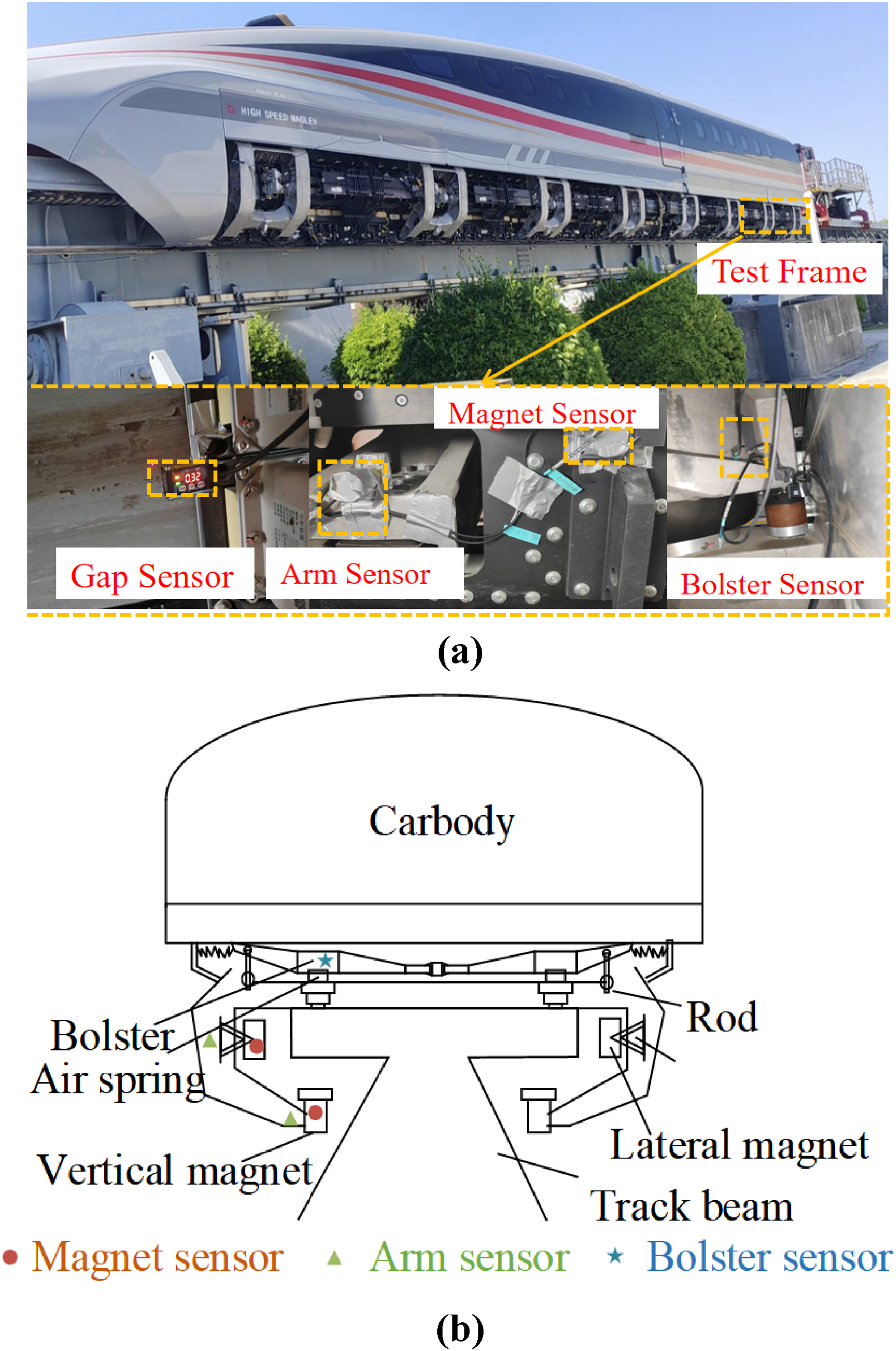
Measured track irregularities
Track irregularities serve as a crucial excitation input for vibrations in high-speed maglev systems. To analyze the relationship between track irregularities and the dynamic responses of the high-speed maglev system, acquiring the track irregularities profile is essential. This study employs the inertial reference method to process measured electromagnet acceleration signals and gap signals, thereby obtaining the track irregularities. The track irregularities detected based on the inertial reference method utilizes train dynamic testing data. Therefore, the irregularities obtained through this method include both static and dynamic irregularities. Static irregularities refer to the track irregularities present without train load, while dynamic irregularities refer to the non-uniform flexible deformations exhibited along the track length under dynamic train loads. The fundamental principle of the inertial reference method is expressed in (1).
As indicated in (1), the acceleration signal requires double integration. To prevent integral saturation, low-frequency interference components must be filtered out. Considering that the Sperling index for evaluating vehicle ride comfort employs a low-frequency cutoff of 0.5 Hz, the acceleration signal was filtered with a low-frequency cutoff at 0.5 Hz. Corresponding to the vehicle operating speed of 40 km/h, the maximum effective wavelength of the track irregularities is 22.22 m. Due to the speed limitations of the test vehicle, the obtained track irregularities presented in this study are not directly applicable to high-speed condition simulations. However, they are sufficient for investigating the correlation between track irregularities and vehicle system accelerations, and can be effectively utilized for low-speed simulation evaluations. High-frequency noise above 100 Hz was also filtered. For the gap signals, low-frequency trend components and high-frequency noise interference were similarly removed using wavelet decomposition and reconstruction. Specifically, the db5 wavelet was employed with a decomposition level of 10. Signals from decomposition levels 3 to 10 were selected for reconstruction.
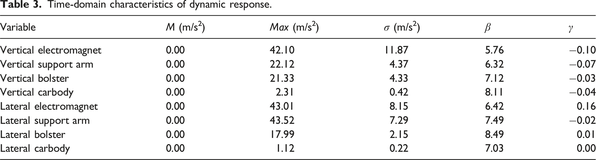
The acceleration signals were double-integrated using the frequency-domain integration method, and the processed gap signals were subtracted to obtain the time-domain signal of the measured track irregularities, as shown in Figures 3(a) and (b). The amplitude of the vertical irregularities fluctuates between −5.51 mm and 4.98 mm, while the lateral irregularities fluctuate between −4.86 mm and 4.91 mm. In terms of amplitude, the vertical irregularities are greater than the lateral irregularities. However, overall, both generally maintain comparable levels. This indicates the presence of relatively larger local vertical irregularities, which may originate from localized factors such as track settlement. Measured track irregularities: (a) low speed test line vertical; (b) low speed test line lateral; (c) Shanghai Maglev line vertical; (d) Shanghai Maglev line lateral.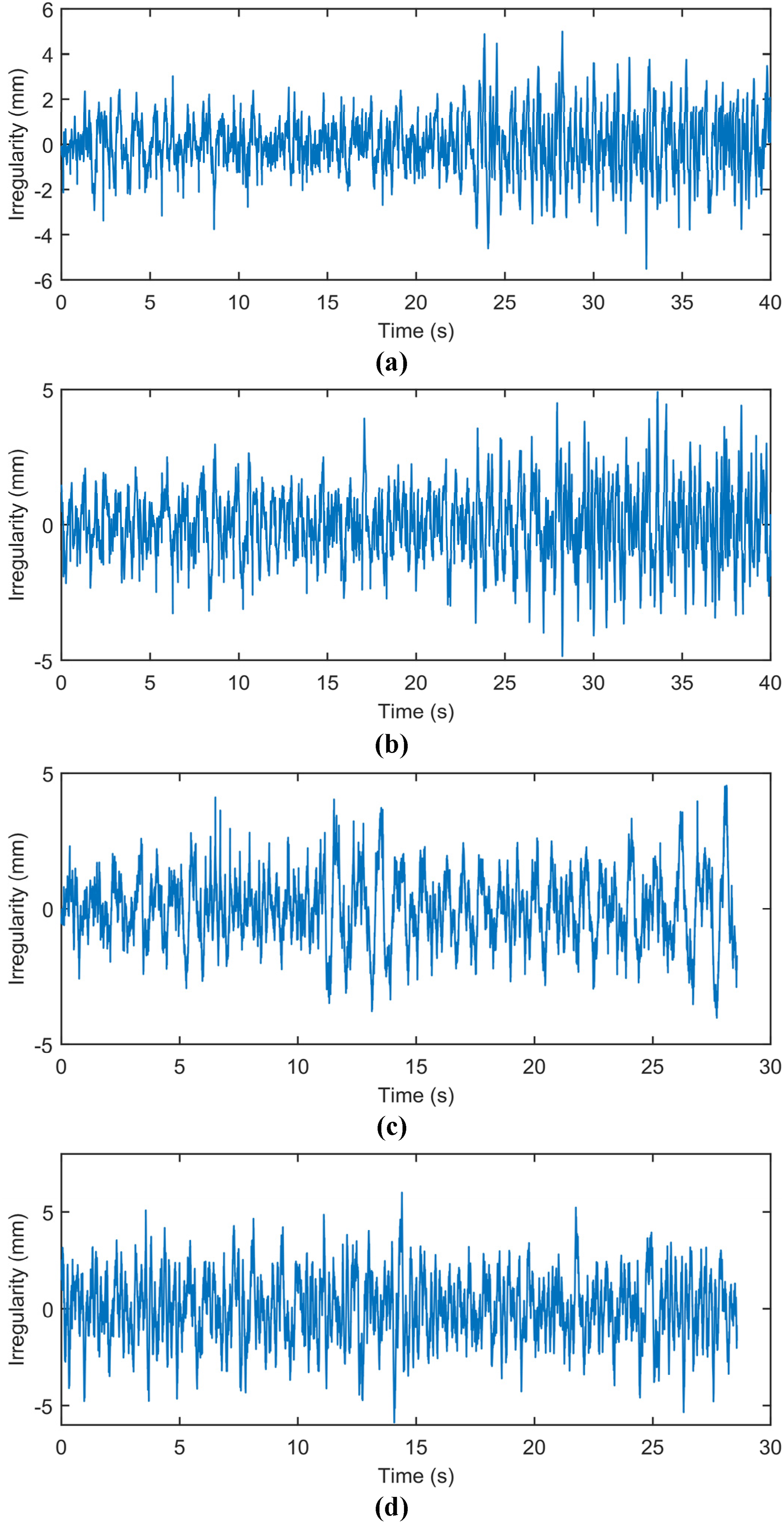
The short-time Fourier transform (STFT) of the measured irregularities is shown in Figure 4, revealing that the energy concentration for both occurs predominantly in the low-frequency range below 15 Hz. STFT of measured track irregularities: (a) vertical irregularities; (b) lateral irregularities.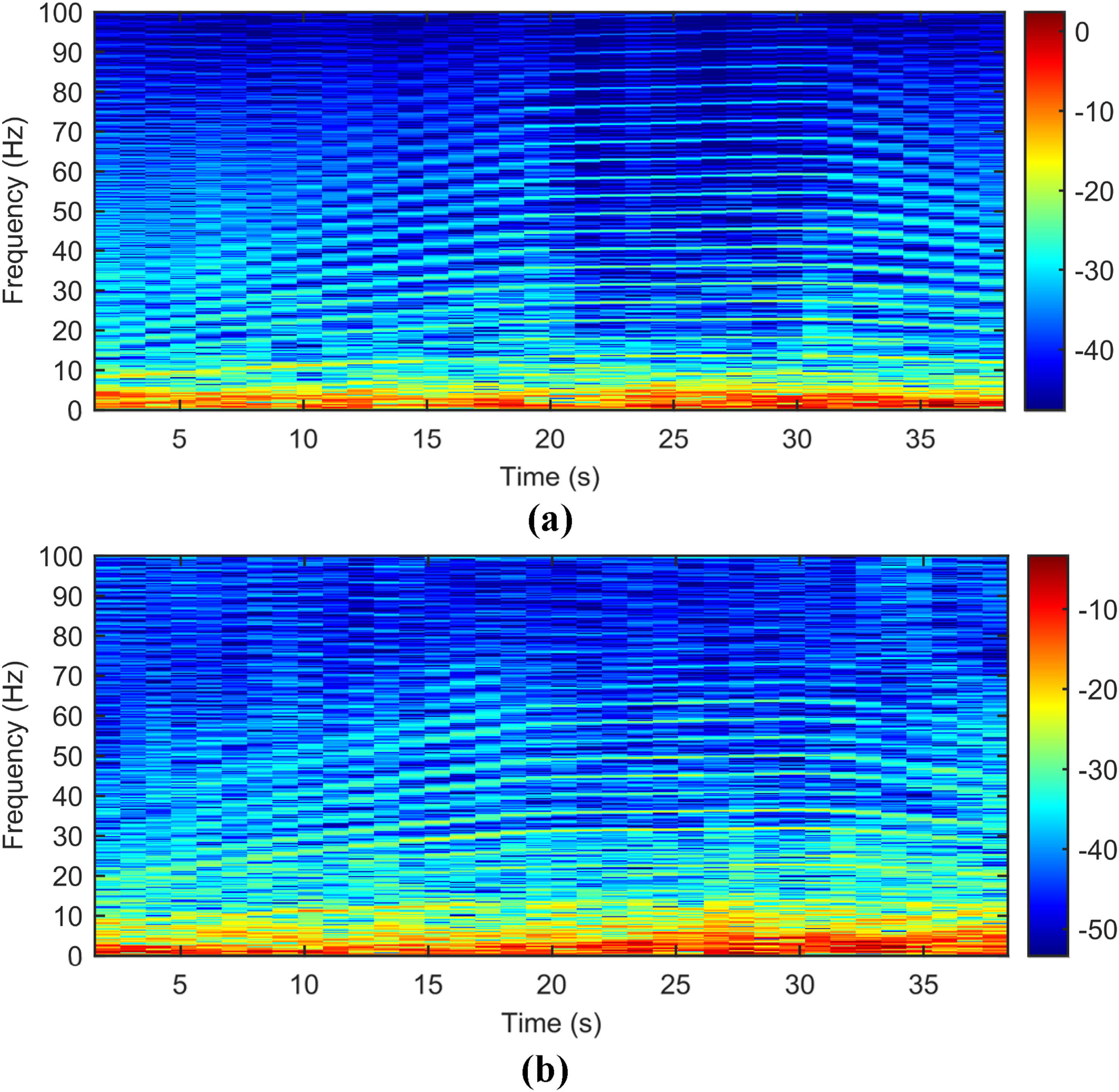
Additionally, to better illustrate the characteristics of EMS Maglev track irregularities, we employed a similar method to process and obtain the track irregularities data under the 430 km/h operating condition of the Shanghai High-speed Maglev Demonstration Line, as shown in Figures 3(c) and (d). A comparison of the probability density function (PDF) of track irregularities between the low-speed maglev test line and the high-speed maglev demonstration line is presented in Figure 5. The irregularities data of the high-speed demonstration line exhibit good consistency with those from the low-speed test line, with the amplitude of irregularities on the high-speed line being slightly larger. Probability density distribution of measured track irregularities: (a) vertical irregularities; (b) lateral irregularities.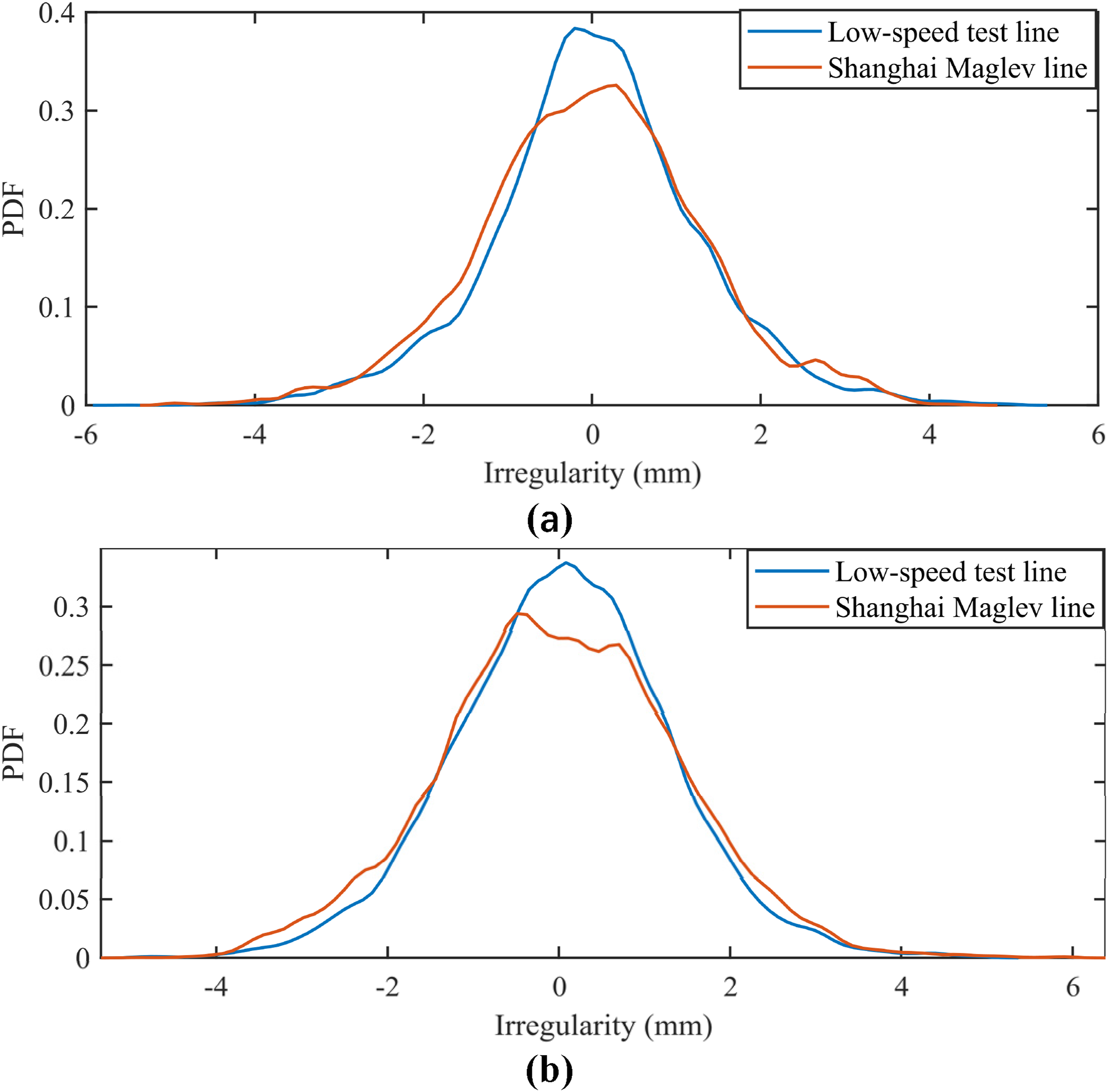

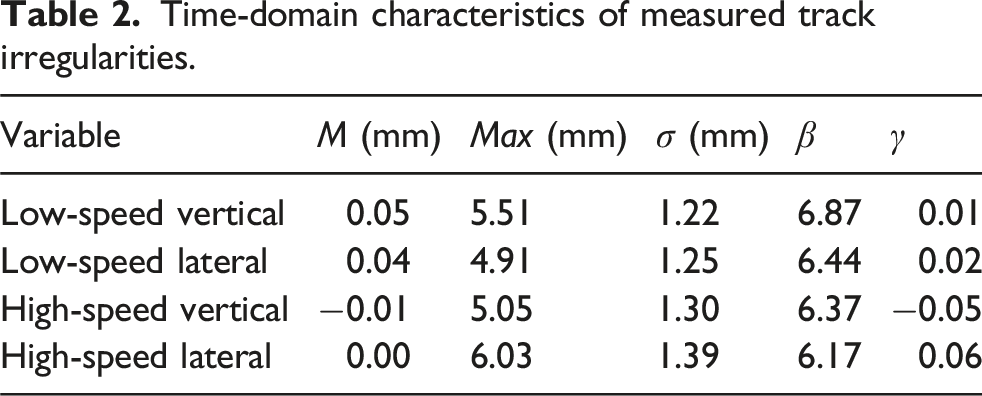
Time-domain characteristics of measured track irregularities.
Vehicle dynamic response
Time-domain characteristics
Similar to the processing of track irregularities, a low-pass filter was applied to all original acceleration data from the vehicle system to remove high-frequency noise above 100 Hz. Figure 6(a) shows the vertical dynamic responses. It can be observed that the vertical acceleration of the levitation electromagnet is significantly higher than that of the frame arm, indicating that the primary suspension components provide effective vibration reduction performance in the vertical direction. The vertical acceleration of the levitation frame arm is roughly equivalent to that of the bolster (part of the secondary suspension), suggesting that the flexible structure of the levitation frame and the air spring have a relatively minor influence on the transmission of vertical vibration. The acceleration of the bolster is significantly greater than that of the carbody, demonstrating that the bolster, hanger rod, and auxiliary floor provide effective vibration reduction performance. Original signals of acceleration: (a) vertical acceleration; (b) lateral acceleration.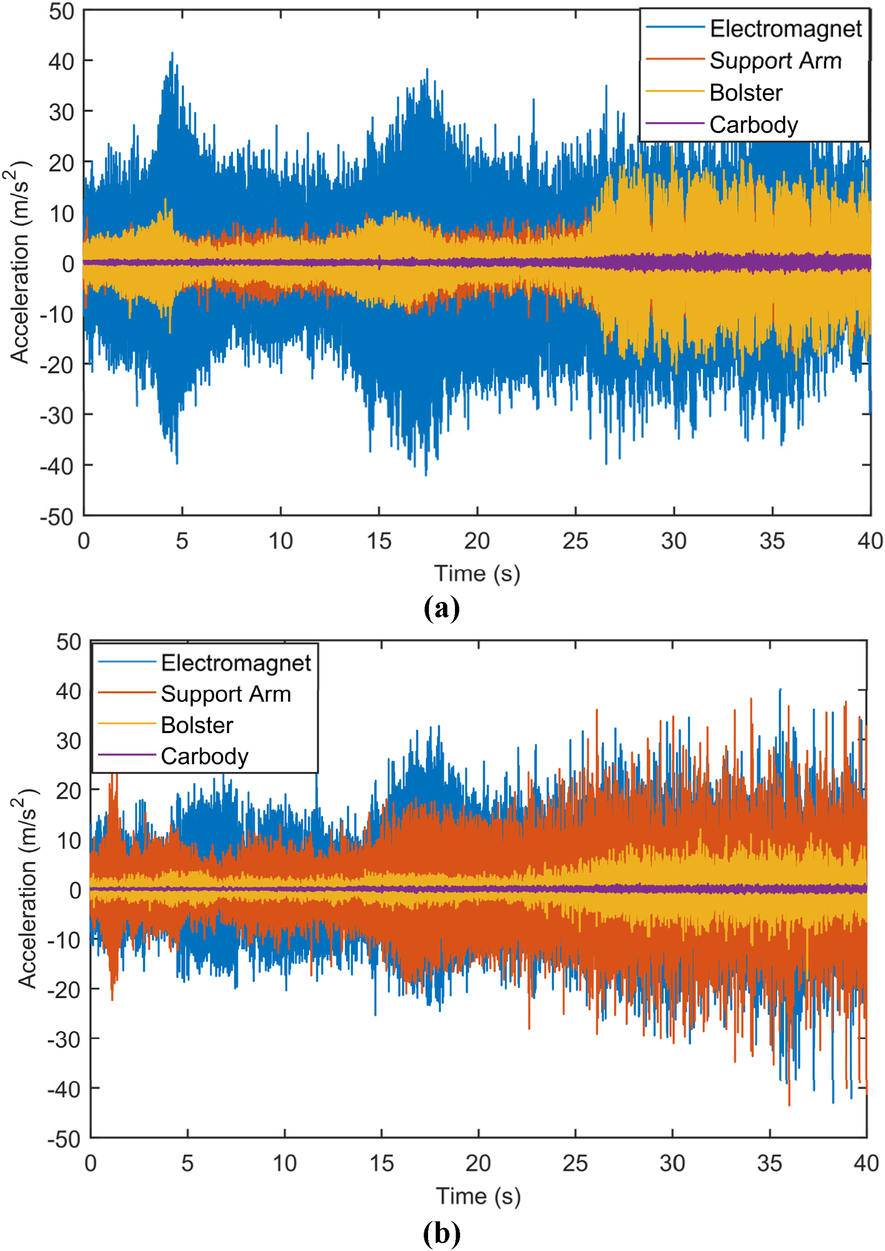
Figure 6(b) shows the lateral dynamic responses. The lateral acceleration of the guidance electromagnet is slightly higher than that of the frame at its articulation point, indicating that the primary suspension components offer limited vibration reduction performance in the lateral direction. Conversely, the lateral acceleration of the levitation frame is significantly greater than that of the bolster, demonstrating that the flexible structure of the levitation frame and the air spring provide significant vibration reduction performance for lateral vibration. The lateral acceleration of the bolster is significantly greater than that of the carbody, indicating that the bolster, hanger rod, and auxiliary floor provide effective vibration reduction performance in the lateral direction.
Time-domain characteristics of dynamic response.
Frequency-domain characteristics
The frequency-domain response of the vehicle dynamic response is shown in Figure 7. For the vertical dynamic response, the dominant frequencies of the electromagnet acceleration response are primarily distributed in three ranges: 0∼15 Hz, 30∼40 Hz, and 50∼60 Hz. The main peaks within these ranges are 0.36 m/s2 at 13.57 Hz, 0.28 m/s2 at 33.30 Hz, and 0.77 m/s2 at 54.57 Hz, respectively. After passing through the primary suspension, the acceleration response of the frame shows little change in the 0∼15 Hz range but significant attenuation in the other two ranges. The peak at 33.30 Hz decreases to 0.18 m/s2, and the peak at 54.57 Hz decreases to 0.29 m/s2. After the effects of the flexible frame and air springs, the acceleration response of the bolster exhibits noticeable attenuation across the entire frequency band. Finally, after the action of the bolster, hanger rod, and auxiliary floor, the acceleration response of the carbody attenuates significantly, with its dominant components concentrated mainly in the low-frequency range of 0∼15 Hz. Single-point peaks appear at 48.87 Hz and 97.72 Hz, which may be the excitation of the flexible carbody’s natural frequencies. It should be noted that due to experimental resource limitations, such as sensor channel availability, this study did not perform elastic modal testing of the vehicle. Frequency-domain characteristics of vehicle dynamic response: (a) vertical; (b) lateral.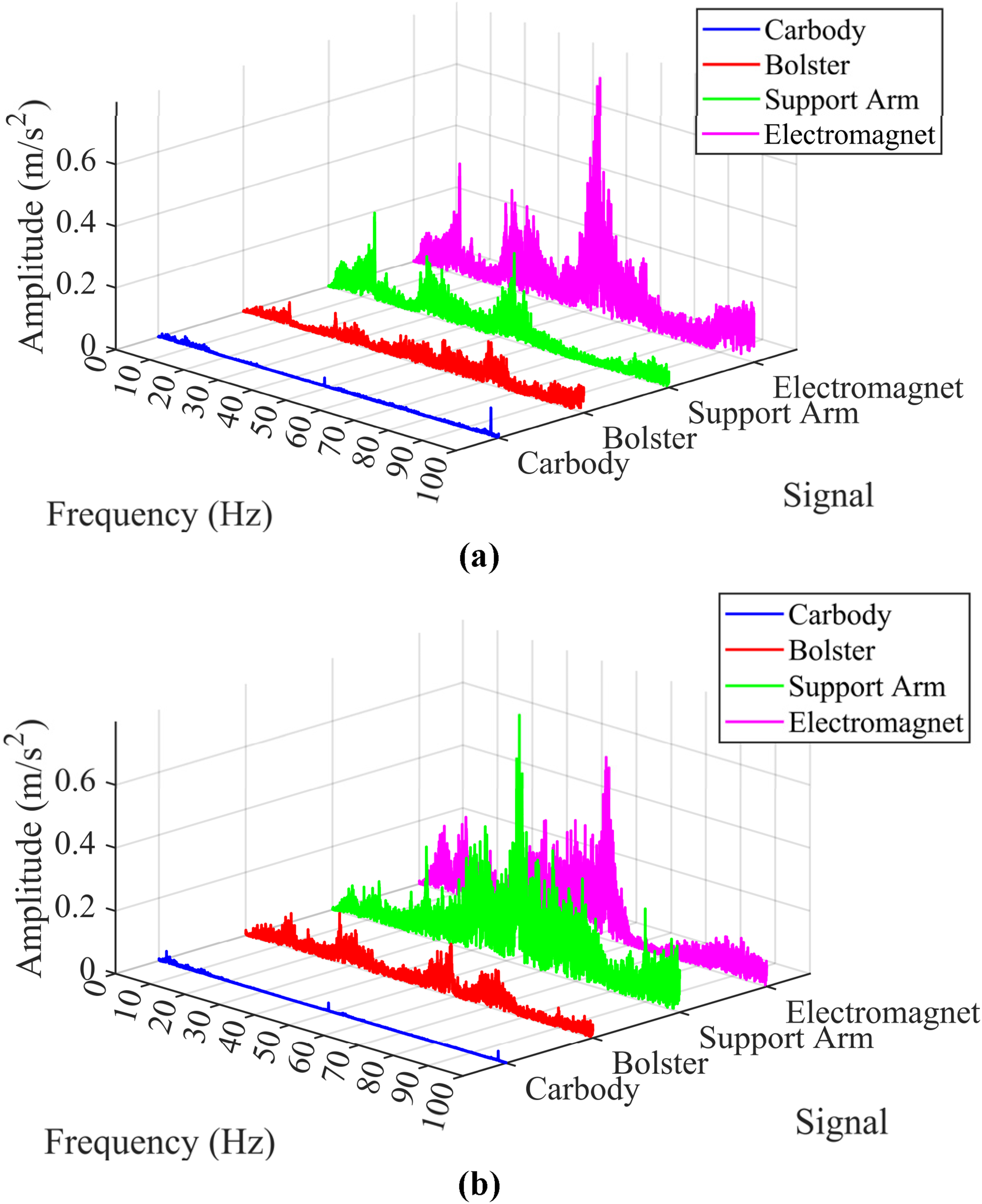
For the lateral dynamic response, the dominant frequencies of the electromagnet acceleration response are mainly distributed in the low-frequency range of 0∼15 Hz and the mid-frequency range of 30∼55 Hz. In terms of peak values, a peak of 0.25 m/s2 occurs at 13.42 Hz in the low-frequency range, and a peak of 0.57 m/s2 occurs at 53.77 Hz in the mid-frequency range. After passing through the lateral primary suspension, the acceleration response of the frame is attenuated in the low-frequency range, for example, the peak at 13.42 Hz decreases to 0.13 m/s2. Conversely, the mid-to-high frequency components are amplified, as illustrated by the increase of the peak at 53.77 Hz to 0.79 m/s2. After the effects of the flexible frame and air springs, the acceleration response of the bolster shows little change in the low-frequency range of 0∼15 Hz but significant attenuation in the mid-to-high frequency range. Finally, after the action of the bolster, hanger rod, and auxiliary floor, the acceleration response of the carbody attenuates significantly, with its dominant components concentrated mainly in the low-frequency range of 0∼15 Hz. Single-point peaks appear at 48.85 Hz and 97.75 Hz. Considering that both lateral and vertical carbody acceleration spectra display remarkably similar single-peak characteristics, it indicates the excitation of coupled modes of the carbody structure.
Coherence analysis
To investigate the relationship between track irregularities input and vehicle dynamic response, this section performs coherence analysis to quantify the frequency-domain correlation between the input and output. The coherence function C
xy
is defined as: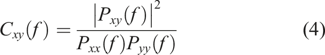
The results of coherence analysis between track irregularities and vehicle dynamic response are shown in Figure 8. The results reveal a strong correlation between track irregularities and the gap, with a notable sharp transition in the coherence coefficient occurring within the 13∼14 Hz frequency range. Above 14 Hz, the gap demonstrates an almost linear correlation with track irregularities. This indicates that the levitation controller maintains certain feedback regulation capabilities for low-frequency track irregularities disturbances, while showing limited effectiveness against high-frequency disturbances where the gap becomes almost entirely linearly dependent on track irregularities. These findings indicate that the levitation controller effectively tracks low-frequency disturbances while remaining insensitive to high-frequency ones, which aligns with its design principle. For the vertical dynamic response, within the low-frequency range of 0∼13.67 Hz, the coherence coefficients between track irregularities and vehicle dynamic responses are generally greater than 0.5. Although the coherence coefficient between track irregularities and the carbody acceleration response does not exceed 0.5 in this low-frequency range, it is significantly higher than in the mid-to-high frequency ranges. Therefore, track irregularities exhibit strong correlation with the low-frequency components of the vertical dynamic response. Comparison with Figure 4(a), illustrating the energy of vertical irregularities is primarily concentrated below 15 Hz, further confirms that track irregularities is the main influencing factor for low-frequency vibrations in the vehicle system. Coherence analysis between track irregularities and vehicle dynamic response: (a) vertical; (b) lateral.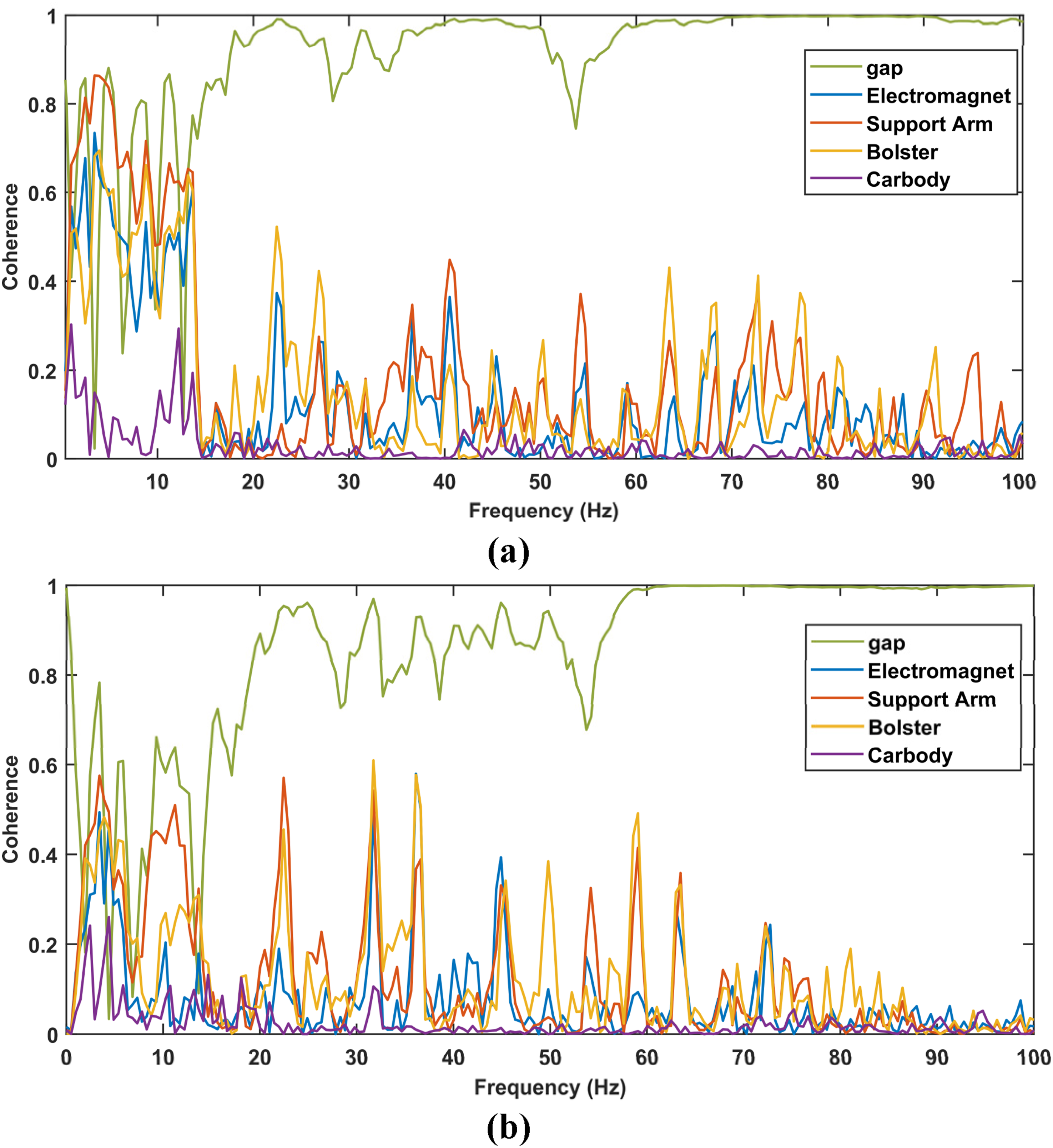
For the lateral dynamic response, except at isolated frequency points, the coherence coefficients between track irregularities and vehicle dynamic responses are generally below 0.5. This indicates a weak linear correlation between the vehicle dynamic response and irregularities of a single track. The primary reason is that the guidance electromagnets are distributed on both sides of the frame, with opposite electromagnetic force directions. There is a strong coupled reaction between left and right electromagnets on the same frame. Consequently, the vehicle lateral dynamic response is jointly influenced by irregularities on both left and right tracks. Nevertheless, within the 0∼13.67 Hz low-frequency range, coherence coefficients remain higher than those in mid-to-high frequency ranges. Thus, track irregularity is still considered the main influencing factor for low-frequency lateral vibrations in the vehicle system.
Vibration attenuation analysis
Time-domain characteristics of dynamic response.
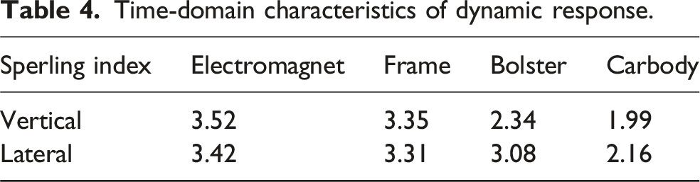
Both the vertical and lateral Sperling indices of the carbody are less than 2.5, with the vertical index being lower than the lateral index, indicating that the prototype vehicle exhibits good ride comfort under low-speed conditions. Through the upward transmission path, the Sperling indices decrease sequentially. The significant difference between the indices for the levitation frame and the bolster suggests that the air spring between them provides effective vibration reduction. The small difference in the ride index between the electromagnet and the levitation frame indicates that the primary suspension between them provides poor vibration reduction performance.
Since the Sperling index is a comprehensive weighted value of acceleration components across various frequency bands, with higher weights assigned to the 0.5 Hz to 20 Hz range, it cannot reflect detailed information about different frequency bands. To further analyze vibration attenuation, this section adopts an alternative approach using vibration acceleration level and 1/3-octave band processing. The vibration acceleration level L
a
is defined as: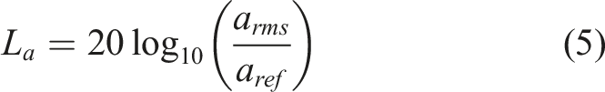
Vertical vibration transmission
The acceleration levels of the electromagnet, support arm, bolster, and car body were calculated using (5) and processed in 1/3-octave bands, as shown in Figure 9(a). Given the sampling frequency of 1000 Hz, the accuracy of bandpass filters decreases at lower center frequencies due to narrower passbands, potentially distorting results. Thus, the minimum frequency was set to 5 Hz. Vertical dynamic responses: (a) acceleration level; (b) acceleration level difference.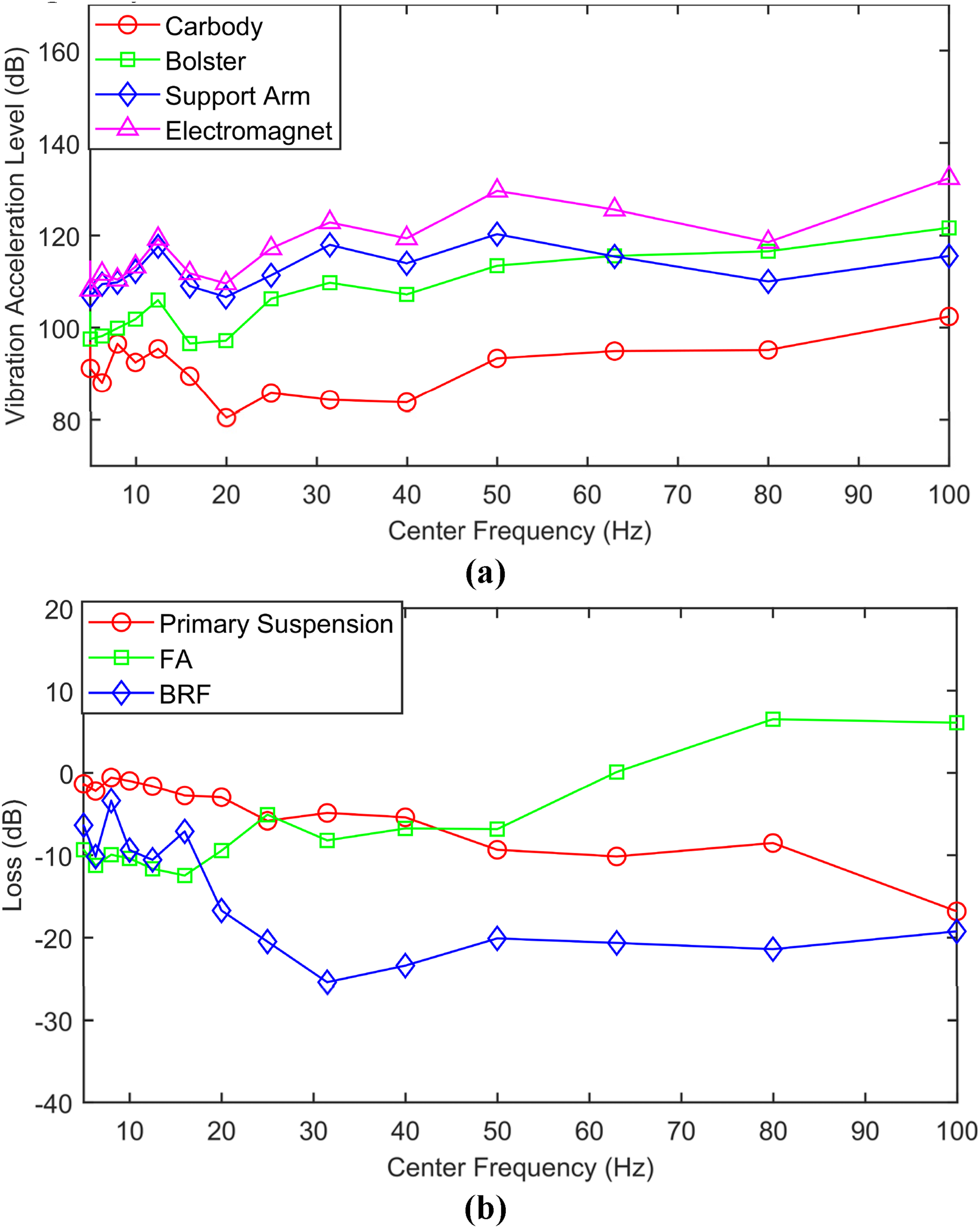
The attenuation between acceleration levels was calculated, with the vibration reduction effect of the primary suspension defined as the acceleration level difference between the electromagnet and the support arm. The vibration reduction effect of the flexible frame and air spring corresponds to the acceleration level difference between the support arm and the bolster. For ease of expression, the vibration reduction effect is hereafter abbreviated in figures and tables as the “FA” vibration reduction effect. The vibration reduction effect of the bolster, hanger rod, and carbody floor, represented by the acceleration level difference between the bolster and the carbody, is hereafter abbreviated in figures and tables as the “BRF” vibration reduction effect.
As illustrated in Figure 9(a), vertical vibration generally decreases sequentially from the electromagnet to the carbody, except for an amplification effect observed in the bolster at frequencies above 63 Hz. As illustrated in Figure 9(b), the primary suspension provides vibration attenuation across the entire frequency band, with its effectiveness improving at higher frequencies and reaching a maximum reduction of −16.80 dB at 100 Hz. Here, the negative sign indicates vibration attenuation, while a positive sign denotes vibration amplification. The flexible frame and air spring demonstrate vibration reduction performance within the 5–63 Hz frequency range, but tend to amplify vibrations above 63 Hz. This vibration amplification may be attributed to the excitation of elastic modes due to the structural flexibility of the frame. The bolster, hanger rod, and auxiliary floor attenuate vibrations throughout the full frequency band, although their attenuation performance is less than −10 dB in the low-frequency range of 5∼16 Hz. Comparatively, the vibration reduction effect of the bolster, hanger rod, and auxiliary floor is the most significant among these components.
Lateral vibration transmission
Similar to the calculation process for vertical dynamics, Figure 10 presents the acceleration level and acceleration level difference for the vehicle’s lateral dynamic responses. The acceleration level of the lateral dynamic responses generally decreases sequentially from the levitation frame to the carbody. However, the acceleration level of the electromagnet is nearly identical to that of the support arm below 50 Hz. Above 50 Hz, the former is even lower than the latter. Regarding vibration reduction effectiveness, the primary lateral suspension demonstrates limited effectiveness. It provides slight vibration reduction within the 5∼50 Hz range, with a maximum vibration transmission loss of −11.85 dB at 8 Hz, but amplifies vibrations above 50 Hz. The flexible frame structure and air spring exhibit vibration reduction of less than −5 dB in the 5∼31.5 Hz range, but demonstrate effective vibration reduction for high-frequency vibrations above 31.5 Hz. The bolster, hanger rod, and auxiliary floor provide effective vibration reduction across the entire frequency band, although their effectiveness is less pronounced in the low-frequency range below 20 Hz compared to the medium-to-high frequency range. Lateral dynamic responses: (a) acceleration level; (b) acceleration level difference.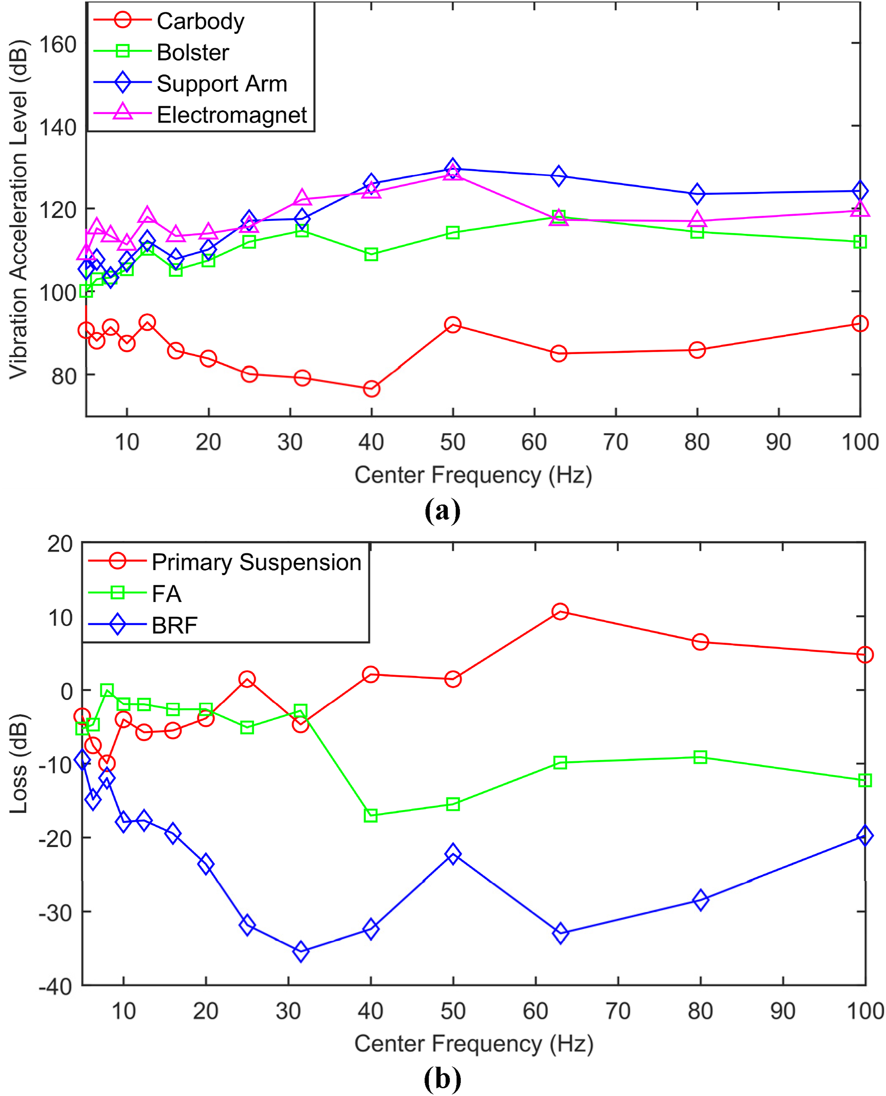
Acceleration level difference across three frequency bands.
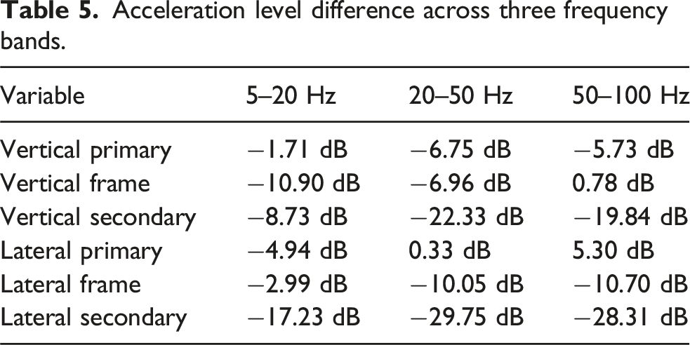
The flexible levitation frame and air spring exhibit good vibration reduction in the vertical low-frequency band, but tend to amplify vibrations in frequencies above 50 Hz. In contrast, their vibration reduction effectiveness is poor in the low-frequency band but becomes significant in the medium-to-high frequency range for lateral vibrations. The bolster, hanger rod, and carbody floor demonstrate effective full-band vibration isolation performance in both lateral and vertical directions, though their vibration reduction effectiveness is relatively lower in the low-frequency band compared to the medium-high frequency ranges.
Conclusion
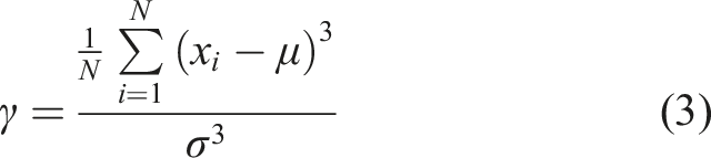
This study conducted dynamic experiment on a high-speed maglev prototype vehicle at Tongji University’s 1.5 km test line. Time-domain track irregularity data were derived from measured acceleration and gap signals. Time-frequency analysis was performed on dynamic responses at multiple vehicle locations. The coherence between track irregularities and vehicle dynamic responses was investigated. Finally, vibration transmission characteristics were analyzed using the vibration acceleration level difference method. Key findings are summarized as follows: (1) Measured track irregularities exhibit stochastic properties. The kurtosis values of vertical and lateral irregularities probability density curves are 6.87 and 6.44, respectively. Energy concentrations for both orientations occur predominantly below 15 Hz. (2) Within the 0∼13.67 Hz low-frequency range, measured track irregularities constitutes the primary influencing factor for vehicle dynamic responses. (3) Track irregularities exhibit high linear correlation with the levitation gap at frequencies above 14 Hz, demonstrating that the levitation control system possesses the characteristics of high-frequency insensitivity. (4) The primary suspension demonstrates limited vibration attenuation effectiveness. The flexible levitation frame and air spring exhibit effective vibration reduction in both the vertical low-frequency range and lateral medium-to-high frequency range. The bolster, hanger rod, and auxiliary floor provide effective vibration attenuation across the entire frequency band.
It should be noted that this study is primarily based on experimental data. Future research could integrate modeling and simulation to investigate the dynamic response characteristics of the prototype vehicle at higher speeds, and establish models that account for the flexibility of the levitation frame, thereby enabling more in-depth investigation into the local elastic vibration characteristics of the vehicle system. Additionally, systematically testing and obtaining the elastic modal parameters of the test vehicle is crucial for deepening the understanding of its dynamic behavior, validating and refining dynamic models, and optimizing the design of suspension and control systems. This will be a key focus of our next phase of research.
Footnotes
Funding
The authors disclosed receipt of the following financial support for the research, authorship, and/or publication of this article: This work was supported by the National Key R&D Program of China 2023YFB4302500, the Key Projects of the National Natural Science Foundation of China (52232013, 52402480, 52441203).
Declaration of conflicting interests
The authors declared no potential conflicts of interest with respect to the research, authorship, and/or publication of this article.