
Abstract
This study presents an innovative quasi zero stiffness (QZS) vibration isolator based on a magic spiral cube (MSC) origami structure. Through the design of its negative stiffness characteristic, the structure achieves a wide constant force constitutive behavior. Addressing the challenge of simultaneously realizing broad QZS properties, load capacity, and structural stability in existing variable-stiffness systems, the proposed isolator achieves a QZS range covering nearly 25% of the unit cell’s deformable range, a load-bearing capacity up to 20 times its own weight, and significantly enhanced low-frequency vibration isolate performance. By integrating nonlinear dynamic modeling and stable state response analysis, the effective operational range of the MSC origami isolator has been successfully extended. Experimental results conclusively validate the model reliability and demonstrate the structure’s strong potential for broadband vibration suppression. This study provides a novel design strategy for flexible metastructure based isolators, showing promising application prospects in vibration reduction for precision equipment and protective systems in aerospace structures.
Keywords
1. Introduction
Low-frequency vibration isolation technology plays a critical role in modern engineering and scientific research, particularly in fields such as precision instrumentation and semiconductor manufacturing (Ge et al., 2022; Hao et al., 2022, 2023). Conventional vibration isolation methods primarily focus on high-frequency vibrations, while it has been noted that low-frequency vibrations, due to their longer wavelength and greater energy, are often difficult to isolate effectively (Chai et al., 2022; Yan et al., 2024). Such low-frequency vibrations not only disrupt the operation of precision equipment but also lead to structural fatigue and damage (Ding et al., 2019; Liu et al., 2024). For such reasons, researchers have proposed a variety of innovative techniques to isolate the low-frequency vibrations (Hao et al., 2022; Lu et al., 2021).
Typically, quasi zero stiffness (QZS) isolators can achieve effective low-frequency vibration isolation by structural design to realize the QZS property within specific frequency ranges (Sun et al., 2024; Wang et al., 2025). In QZS isolators, the stiffness design is essential to achieve the high-static-low-dynamic-stiffness (HSLDS) (Noh et al., 2024; Teng and Gao, 2025) and various types of the HSLDS isolators have been developed in terms of mechanical, magnetic, cam-roller, bistable beam and bio-inspired designs (Ding et al., 2023; Huang, 2024; Shi et al., 2025; Song et al., 2025; Yang et al., 2025). Ding et al. (2023) and Li et al. (2024) proposed a modular QZS vibration isolator based on the compliant constant-force mechanism, which achieves HSLDS characteristics through the parallel combination of a positive-stiffness rhombus mechanism and a bistable beam. Huang et al.(2025) developed a two-stage hybrid vibration isolator that integrates a nonlinear energy sink (NES) with a negative stiffness spring (NSS), leveraging their respective nonlinear characteristics and stiffness cancellation effect to enhance energy transfer efficiency and system stability. The design of these QZS vibration isolators fully considers the effects of structural form, physical parameters, and geometric nonlinearity on the natural frequency and amplitude-frequency response. The isolation bandwidth can be partially extended by lowering the natural frequency so that the vibration amplitude and coupling forces between the system and the base are reduced, which have become a central research focus on the field of vibration suppression. However, lowering the natural frequency implies that the stiffness of the isolator would decrease, resulting in the loss of load capacity. Additionally, the pre-compression amount of the horizontal springs in the classical QZS isolators with HSLDS property is related to the negative stiffness but the isolation is easy to lose stability if the amount is larger than the designed value. For example, it is founded that the pre-compression amount of the horizontal springs exceeds 84%, the designed isolator would lose its stability in a three-spring QZS isolator (Liu and Li, 2025). It is also seen that the friction at the cam-roller contact point varies with the normal force and affects the isolator’s performance (Yu et al., 2025). To avoid the instability and friction, some origami structures with specific geometric and mechanical properties are used to design the isolator since they have negative stiffness and multi-stable characteristics and, therefore, can integrate the HSLDS to isolate the low-frequency vibration (Yu et al., 2024; Zhou et al., 2024). The origami structures not only represent a fundamental distinction from traditional isolators (Novelino et al., 2020), but also display a vast design space capable of achieving tunable size, reconfigurable topology, folding-induced unconventional mechanical properties and tunable stiffness properties. Thus, origami structures can enable broad potential for practical engineering applications, which may be employed to attenuate vibrational energy (Li et al., 2020).
Recently, it has discovered that the change occurs from exploring single mechanical properties to multifunctional coupled design for origami-based metastructures, in which the geometric nonlinearity and reconfigurability are employed to actively modify their mechanical properties (Umair and Hou, 2024). Adjusting the linkage angles and the gap between the central shaft and springs, Inamotoc (2019) and Ishida et al. (2016) employed the geometric nonlinearity of the Kresling origami to achieve the precise control for the static load capacity. Han et al. (2021) proposed a QZS isolator inspired by the dissipative behavior of the SMO origami structure through its reconfigurability. The nonlinear stiffness and damping induced by folding effectively enhance vibration isolation performance in the low-frequency range and simultaneously broaden the effective isolation bandwidth. Sadeghi and Li (2019) investigated a tubular fluidic series origami for vibration isolation, which provided the relationship between the internal fluid pressure and the isolation effectiveness, where the pressure was used to control the static load-bearing capacity and the structure was used to enhance energy dissipation due to its asymmetry and hysteresis. With growing demand for the broader frequency range, origami configurations have been continuously evolving (Shi et al., 2025; Xu et al., 2025; Yu et al., 2025; Zhou et al., 2024), such as achieving programmability of key performance characteristics including bandgap properties and QZS domains (Li et al., 2020; Zhao et al., 2023). The anti-twist coupled structure designed by Liu et al. achieved a 200% broader bandgap compared to the conventional configurations (Liu et al., 2024). The strategic integration of multi-physics coupling mechanisms opens new functional dimensions. A breakthrough was demonstrated by Yu et al. (2024), whose truss-spring-inertia composite structure triples the low-frequency vibration isolation bandwidth via intelligent equivalent mass regulation.
Although significant progress has been made in low-frequency vibration isolation using origami-based metastructures (Han et al., 2025; Li et al., 2025), the paramount challenge in designing a full-frequency vibration isolator remains the simultaneous achievement of a broad QZS range, adequate load capacity, and structural stability. This challenge comes from several inherent contradictions: first, there exists a conflict between load capacity and vibration isolation performance, namely, reducing the natural frequency to achieve low-frequency isolation often compromises structural stiffness, thereby impairing load capacity; second, most existing inverse design approaches focus on single index performance, lacking a multi-objective design capable of optimizing both isolation efficiency and load capacity simultaneously; furthermore, current research frequently relies on complex multi-unit stacking or coupled structures to achieve target performance, leaving the key problem of realizing broadband isolation and high load capacity synergistically through simple configurations largely unresolved. We consider the origami structures to be a promising candidate for addressing these challenges. This is the reason why the MSC origami is selected for the present investigation. It is found that the MSC origami possesses a negative stiffness deformation. By connecting it in parallel with a positive linear stiffness element, a new QZS isolator with a broad operational range is created. Within this range, the new isolator not only provides vibration isolation in full-frequency domain but also achieves load-bearing capacity in its nonlinear stiffness. Experimental results validate new isolator’s efficacy in broadband vibration isolation, paving the way for its application in precision equipment and engineering. This paper is organized as follows. In Sect. 2, the geometric modeling and constitutive relationships of the structure will be presented, along with the nonlinear dynamic equivalent model. Sect. 3 gives an analytical investigation of the vibration response, which revealing resonance characteristics under displacement excitation. Configuration design and vibration isolation experiments are performed to validate the theoretical framework in Sect. 4. Some novel conclusions are represented in Sect. 5.
2. Tunable stiffness design of a magic spiral cube (MSC) origami structure
2.1. Geometric configuration
A square MSC origami structure configuration without deformation is shown in Figure 1(a), consist of a top plate, a bottom plate, and four side surfaces. In the MSC origami structure, L is the side length of the cube, abcd the four points of top plate and ABCD the four points of bottom one. Assumed four side surfaces are flexible so that MSC can be folded through z-direction deformation, possibly resulting in two stable states. Since the top and bottom plates have much larger thickness than the side surfaces, they are considered as rigid plates. As shown in Figure 1(b), the configuration for fully deployed state is considered as the original state, which is a stable state of the MSC origami structure. A coordinate system with origin O is established at the geometric center of the unit. (a) MSC origami structure and true creases; (b) geometric configuration of an undeformed MSC origami structure and its top view after compressive deformation in z-direction.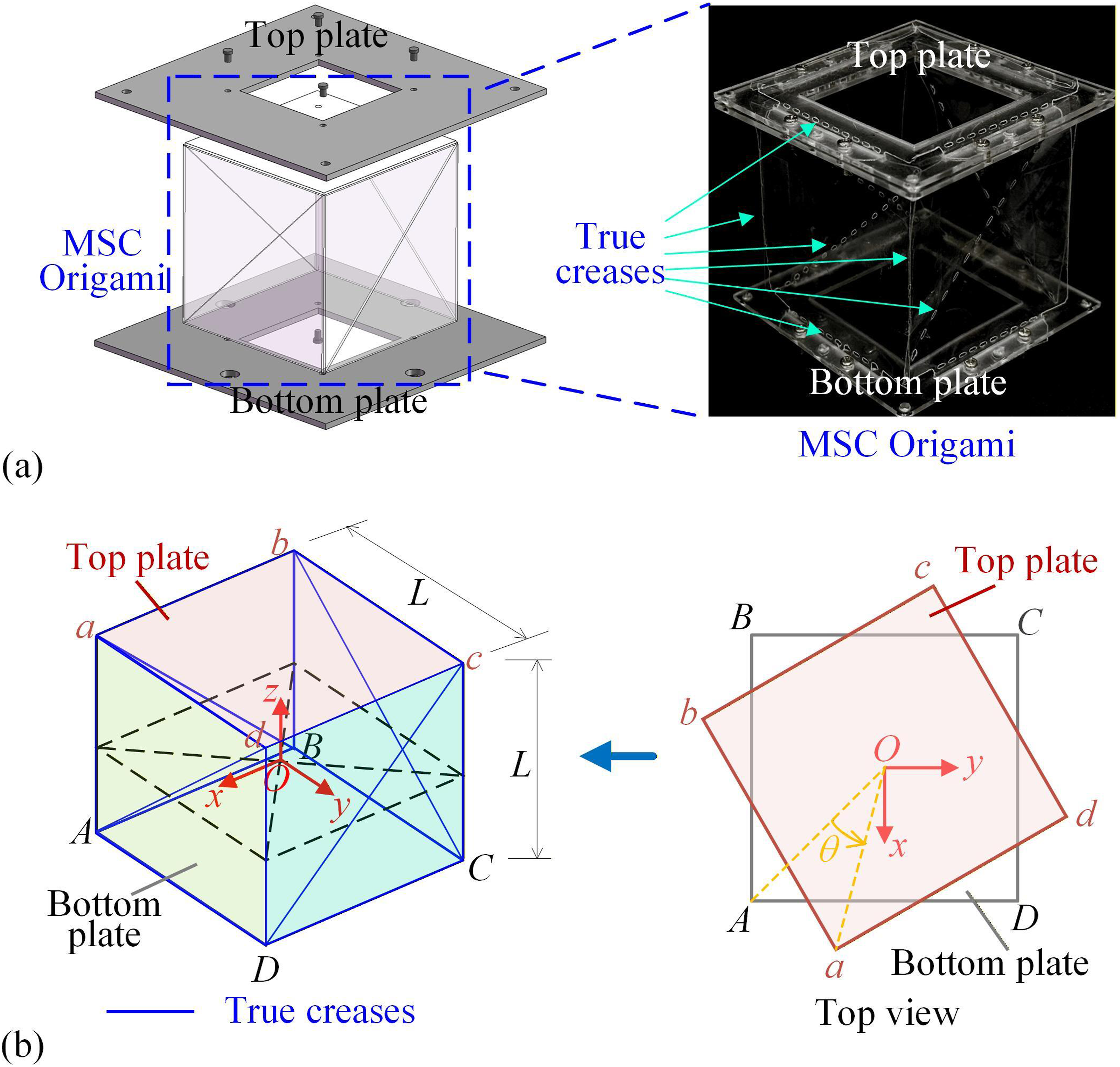
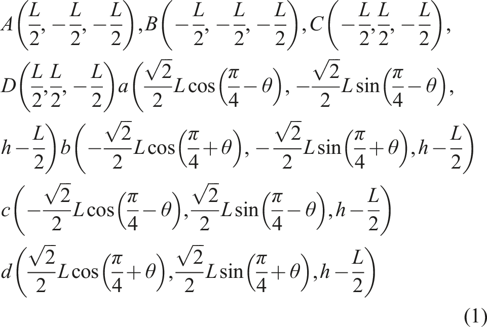
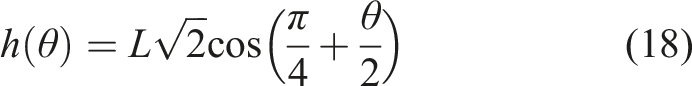
For z-direction compression deformation, the top plate would have a rotation motion with angle θ, as shown in Figure 1(b). Thus, followed from Figure 1(b), for z-direction compression deformation, the coordinates of all points of top, bottom and side surfaces of the MSC origami in the coordinate O can be given by
In the study on the folding process of the MSC origami structure, we observe that the side surfaces undergo out-of-plane deformation as shown in Figure 2. It is founded that this type of out-of-plane deformation can be qualitatively described by virtual creases. Compared to the traditional truss modeling method, the virtual crease model offers a more complete representation. While truss models are convenient for modeling and yield analytical expressions, they overlook the twisting of facets along the creases. In contrast, the virtual crease model effectively captures the out-of-plane deformation which induced bistable behavior and negative stiffness of the MSC origami structure under compression, as illustrated in Figure 3. (a) MSC origami sample for z-direction compression, compressive deformation diagram of it and the deformation of one line in side surface in the new stable state, called compression state; (b) the virtual creases occurring on the side surface due to out-of-plane deformation and its geometric condition due to virtual creases. The relation between strain energies (for true creases, virtual creases and the whole structure), restoring force, stiffness and displacement z.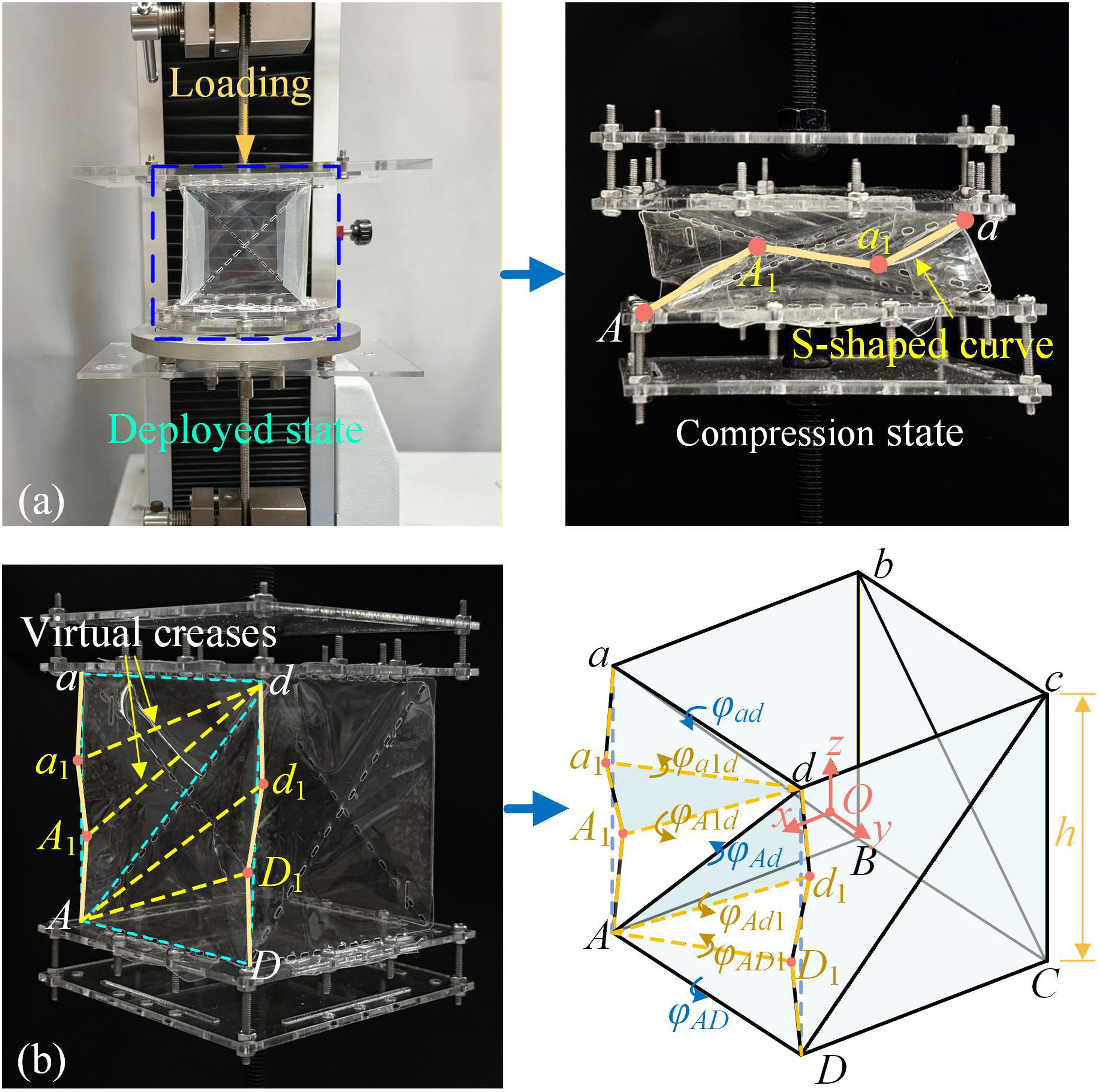
Unfortunately, it is exceedingly difficult to quantitatively determining the location of the virtual crease. We utilize experimental observation and results to figure out the location of the virtual creases. Figure 2(a) displays the uniaxial compression test of an MSC origami sample, and Figure 2(a) shows the deformation of side surface under compression, especially the out-of-plane deformation to induce new creases. As observed in Figure 2(a), the straight line aA in the side surface is deformed into an “S-shaped” curve, where points a1 and A1 are two points positioned at the trisection points on the line aA, as shown in Figure 2(b). It is also seen from Figure 2(a) that the line remarked in aA is elastic, leading to the new creases aa1, a1A1 and A1A during deformation. In the following analysis, we define the creases occurring in deformation to compression state as virtual creases.
Since each true crease at diagonal line divides each side surface into two triangles of equal area and the structural symmetry, without loss of generality, the analysis of virtual ceases in triangle adA is given here. From Figure 2(b), it is hypothesized that the virtual crease a1d bulges outward, while and the one A1d curves inward. To determine the constitutive relationship of the structure, it is necessary to provide the coordinates of all points during the deformation process. Based on the coordinates of the points of top and bottom plates as equation (1), the position of virtual crease point a1 relative to point a can be determined through deformation compatibility conditions. Taking triangle adA as the example, the distance between vertex a and vertex a1 is equal to one-third of the crease length l
aA
, and similar equations apply to other points. Thus, the coordinates of the virtual crease points a1 and A1 can be quantitatively determined as shown in Figure 2(b), given as
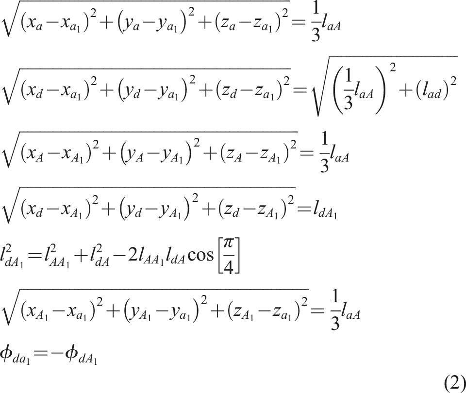
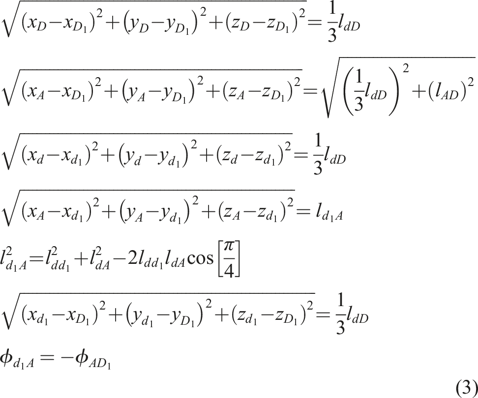
Similarly, based on the geometric compatibility of triangle dAD, the coordinates of points d1 and D1 can be written as:
Once all the coordinates of the points of virtual creases in the MSC origami structure are obtained, the virtual creases position corresponding to the out-of-plane deformation can be determined by lines a1d, A1d, d1A and D1A. Taking crease ad as an example, the dihedral angle is denoted as
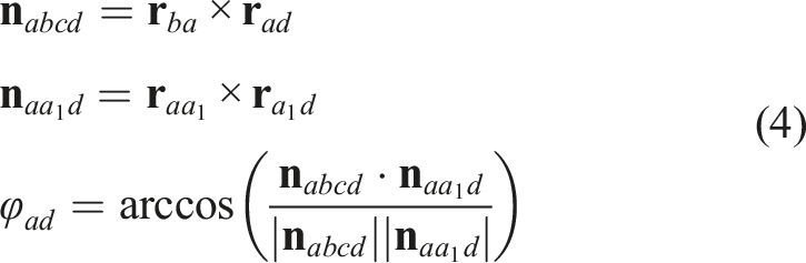
Similarly, all dihedral angles of true creases and virtual creases on side surface adDA for compression are given as
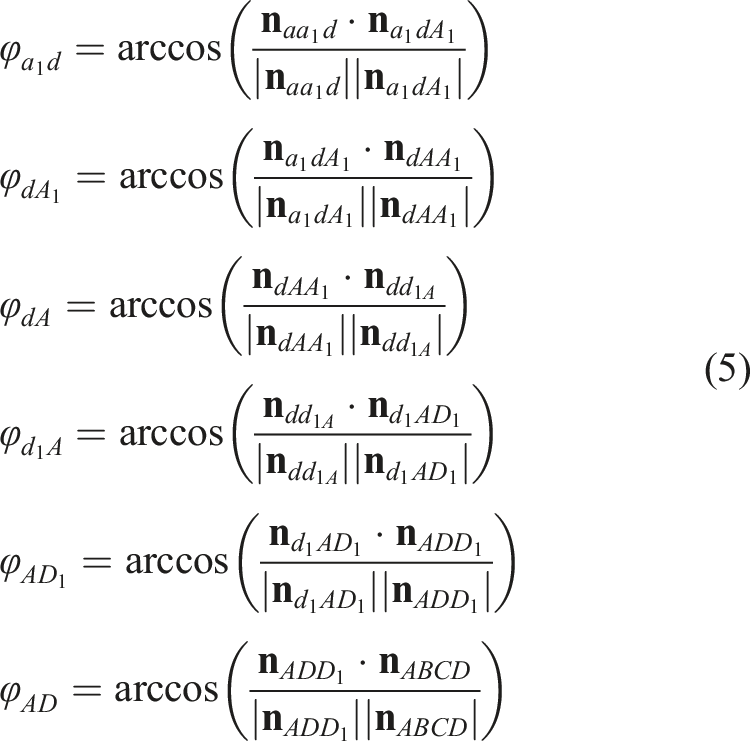
By extension, the normal vectors of all surfaces and the dihedral angles along the creases in the MSC origami structure can be determined.
2.2. Strain energy of one MSC origami structure
The geometrical conditions at true or virtual creases in the MSC origami structure have been established in the previous section based on geometrical analysis. This section focuses on the derivation of sum strain energy. As the deformations occurring at true creases and virtual creases are obtained, the strain energy of one MSC origami structure can be obtained through the dihedral angles. For instance, in the side surface adDA, the strain energy of true creases is denoted as ΠTure, here comprising three creases: ad, Ad and AD; similarly, the strain energy of virtual creases is denoted as ΠVirtual, here comprising four creases: a1d, dA1, d1A, and AD1. Based on linear elastic assumption, the expressions of ΠTure and ΠVirtual are given as
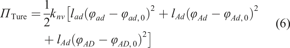
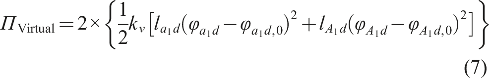

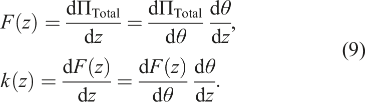
The linear elasticity assumption is adopted to simplify the strain energy calculation of the virtual creases, while the actual nonlinear behavior is compensated for via experimental fitting, thereby balancing model complexity with prediction accuracy. By computing the first and second-order derivatives of the total strain energy with respect to the displacement z, the restoring force and stiffness can be given as
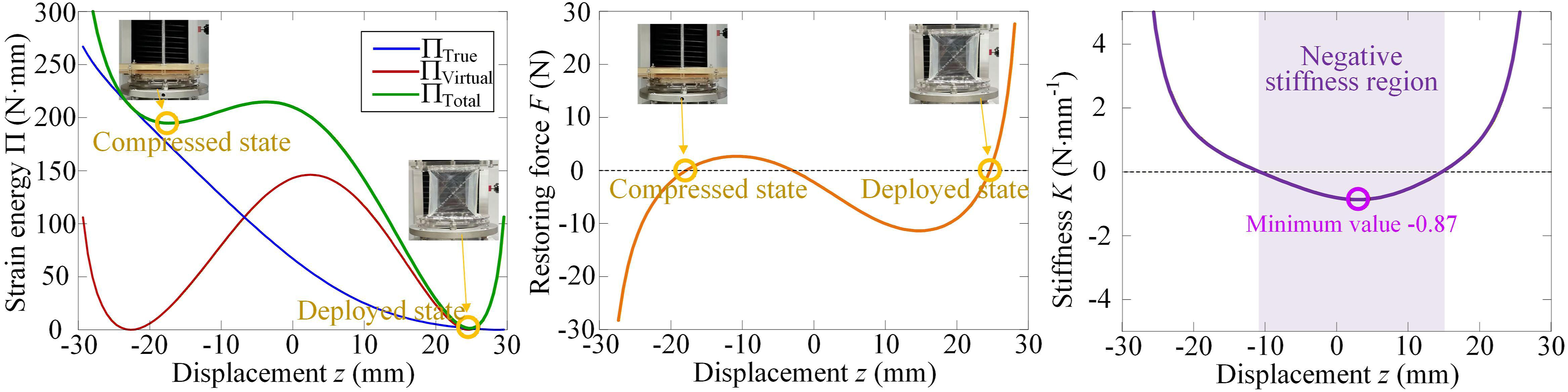
The strain energy, restoring force and stiffness of the MSC origami structure are shown in Figure 3. Assuming the MSC origami structure has size with side length of L = 60 mm, Figure 3 shows the strain energy of true creases, virtual creases and the sum one for displacement z. It is seen from Figure 3 that the strain energy ΠTrue (Blue Line in Figure 3, without considering the deformation occurring at the virtual creases, exhibits a monotonically decreasing trend and presents only one stable state, which is inconsistent with pre-experimental observations. In contrast, the sum stain energy ΠTotal displays two stable states because the strain energy of virtual creases has multi-stable states property. This result therefore demonstrates the necessity of the virtual creases attached to the out-of-plane deformation of the side surfaces. Then, Figure 3 shows the restoring force and stiffness of the MSC origami structure, respectively. The restoring force curve reveals two stable states, and correspondingly, the stiffness curve further indicates a negative stiffness region around the unstable state. Therefore, by combining with specific designed positive stiffness, the QZS property can be achieved, providing a foundation for application for vibration isolator.
To validate the effectiveness of the theoretical stiffness model, a quasi-static axial tension-compression experiment is carried out as shown in Figure 4. The test is conducted on a universal testing machine shown in Figure 4(a), wherein axial displacement loading is applied on the structural specimen at a low rate, while the load-displacement response data is synchronously acquired by computer. Based on the analysis of the loading curve as Figure 4(b), the experimental data is compared with those calculated from the theoretical formula. This comparison directly demonstrates the accuracy and predictive capability of the theoretical model, thereby providing a reliable parametric foundation for subsequent dynamic analysis. (a) Quasi-static unidirectional tensile test of a MSC origami structure sample; (b) the experimental force-displacement curve of the MSC origami structure.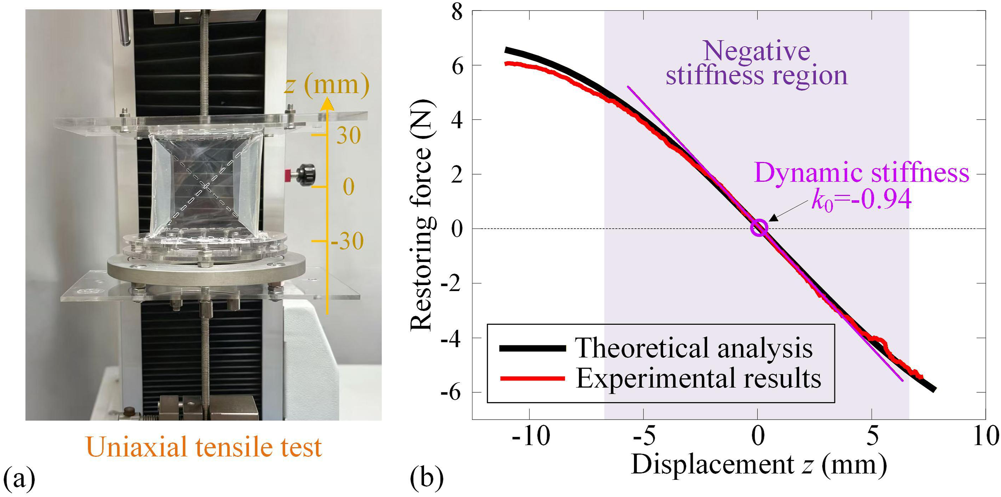
2.3. Design criterion for realization of zero stiffness property
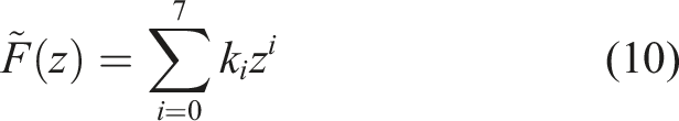
According to the theoretical and experimental results in Figure 4(b), the MSC origami structure displays negative stiffness existing in a specific region. We desire that the MSC origami structure should be effective and efficient for vibration isolation, and thus, it needs a region for QZS property rather than one-point QZS. Upon the experimental data of restoring force with displacement in Figure4(b), function fitting with basic parametrical regression is carried out. Then, the restoring force constitutive, with equilibrium position as the coordinate origin, can be represented by a seventh-order polynomial approximation as
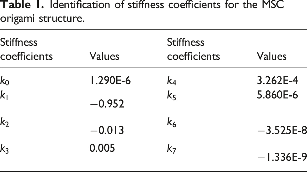
Identification of stiffness coefficients for the MSC origami structure.
By moving the equilibrium position to the origin, the expression (10) must satisfy the following constraints as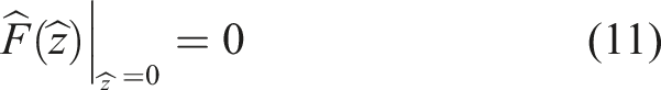
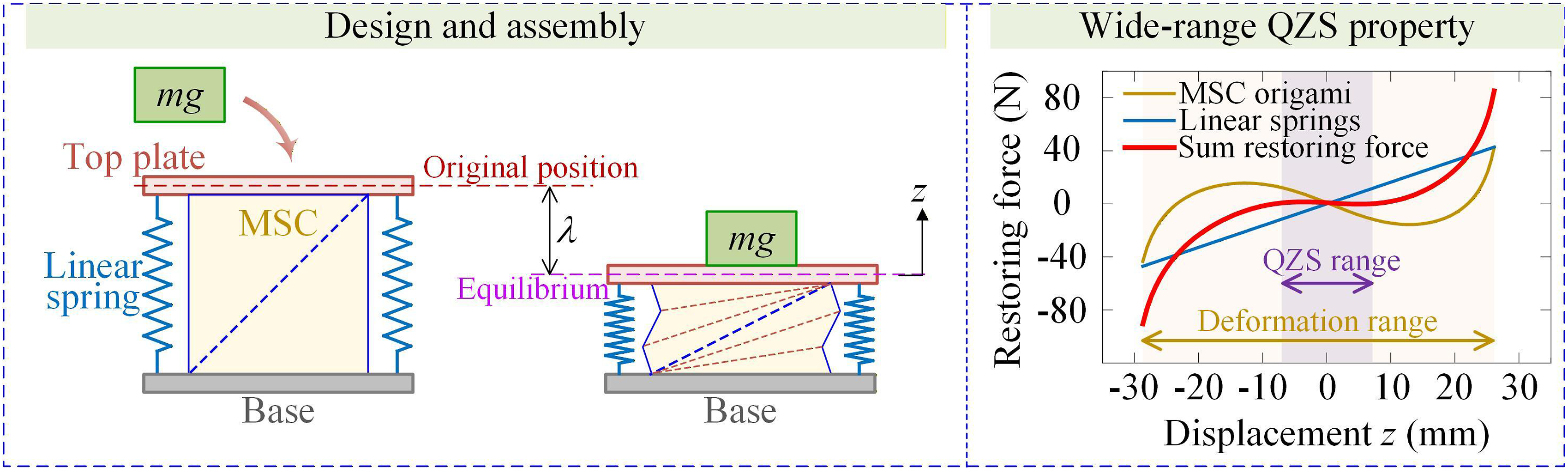
To achieve a region for QZS property for vibration isolation, a linear spring with positive stiffness coefficient is introduced to counteract the negative stiffness of the MSC origami structure as Figure 5. Assuming the linear positive stiffness coefficient is The design and restoring force of the isolator.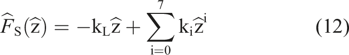
The obtained coefficients satisfy equation (11) and exhibit small errors, thus demonstrating the model’s capability to accurately capture the nonlinear mechanical behavior of the structure.
To ensure that the system exhibits QZS characteristics near the equilibrium position, the following design criteria must be additionally satisfied: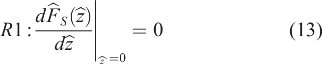
Figure 5 illustrates the restoring force of the QZS vibration isolation structure. The yellow curve corresponds to the original MSC origami structure, while the blue straight line indicates the linear spring element, demonstrating a linear proportional force-displacement relationship. The red curve represents the QZS vibration isolation system formed by connecting the MSC structure and the linear spring in series, whose mechanical behavior results from the coupling effect of the two components. Owing to the finite thickness of the physical structure, which prevents it from being compressed to the theoretical zero height, the actual achievable deformation range is from −29.1 mm to 26.6 mm. The QZS range is defined as the displacement interval where the stiffness threshold is [-10%kL, 10%kL], while the deformation range is given by
According to calculate the force-displacement relationships for three samples of different sizes (L = 20, 60, and 100 mm), as shown in Figure 6(a), all samples exhibit similar QZS property in their restoring force curves. Figure 6(b) presents the force-displacement curves of the three samples, where the purple shaded area indicates the QZS range of the structure, and the yellow shaded area represents the deformation range. The ratio of the QZS range, which can be calculated using equation (14), serves as one of the index performance indices for evaluating the structure. (a) Restoring force of the QZS isolator with different unit cell sizes; (b) ratio of the QZS range to the deformable range for each sample and ratio of loading capacity to self-weight for each sample.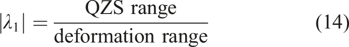
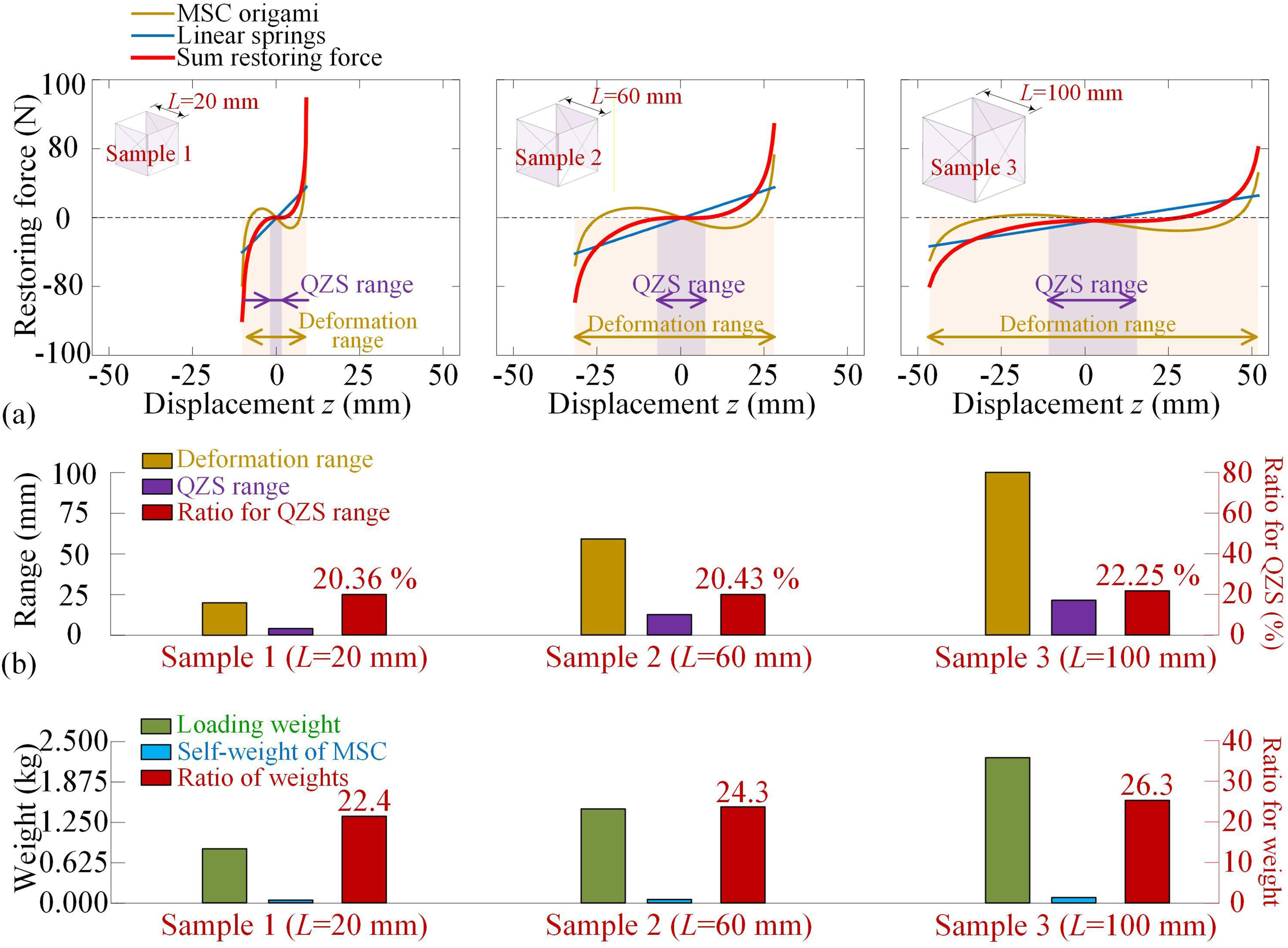
The QZS range percentage demonstrates remarkable stability, remaining within a broad band of 20% to 25% across different unit cell sizes. This indicates that the structure can preserve QZS over an extended displacement range, which substantially enlarges the effective operating domains for vibration isolation. Within the displacement range of highlight part in Figure 6, the isolation system exhibits significant and broad QZS characteristics: in this interval, the force variation is minimal, the curve remains nearly horizontal, and the dynamic stiffness approaches zero. This QZS range indicates that the system can maintain extremely low dynamic stiffness over a large displacement range, thereby providing a critical mechanical foundation for achieving highly efficient low-frequency vibration isolation. An increase in the dimension L leads to longer real creases and correspondingly widens the absolute QZS range, although L cannot be increased without limit due to stability and weight constraints. Compared to the individual MSC structure or the independent linear spring, this composite system effectively expands the isolation range across a wide displacement domain through the mutual cancellation of positive and negative stiffness, demonstrating excellent engineering applicability and controllable force transmission characteristics.
To further analyze the vibration isolation performance of the system and to develop its dynamic model, the static equilibrium equation under a supported mass m can be expressed as:
Correspondingly, the loading capacity serves as another index performance indicator for the structure. It is defined by equation (16) and illustrated in Figure 6(b).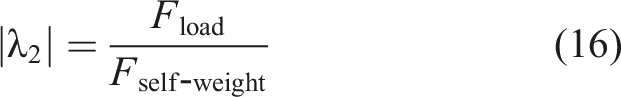
Sample 1, with a mass of 20 g, supports a load 22.4 times its own weight, while Sample 2 and Sample 3 achieve the ratios of 24.3 and 26.3, respectively, significantly outperforming conventional designs. Self-weight includes only the mass of the MSC origami structural unit itself, excluding the mass of auxiliary components such as linear springs and rotating discs. When L increases, the overall size of the structure enlarges and the lengths of its real creases increase accordingly which provide positive stiffness during deformation. This results in a higher load capacity with larger L. Importantly, both λ1 and λ2 remain stable across different scales, demonstrating the scalability and robustness of the MSC isolator design. These results demonstrate the design’s core advantage of achieving high load-bearing capacity while maintaining lightweight characteristics. However, if the required load-bearing capacity is not met during the isolation process, it becomes necessary to reconfigure the corresponding positive stiffness springs to reestablish the QZS range and achieve effective isolation.
3. Vibration isolation effectiveness of the MSC origami-based isolator
3.1. Dynamic model
As illustrated in Figure 7(a), a rotating disc is connected to the base plate of the MSC structure, with this rotation disc, the rotation displacement accompanied by the axial direction displacement of MSC origami structure can be considered as free rigid body motion without any constraint. Thus, when the proposed MSC origami-based isolator is subjected to displacement excitation in vertical direction, it can be considered as a single-degree-of-freedom vibration system for vibration isolation, as shown in Figure 7(b). At the static equilibrium position figured out by the previous study, which is fixed as the origin for vibration response, the absolute displacement of the top plate along the axial direction is assumed as u. Similarly, the displacement of the base is defined as u
z
along the axial direction of the structure. Then, the relative displacement coordinate of the isolation object with respect to the base can be defined as (a) Design schematic of the MSC origami-based vibration isolator; (b) equivalent mechanical model of the proposed MSC origami-based vibration isolator.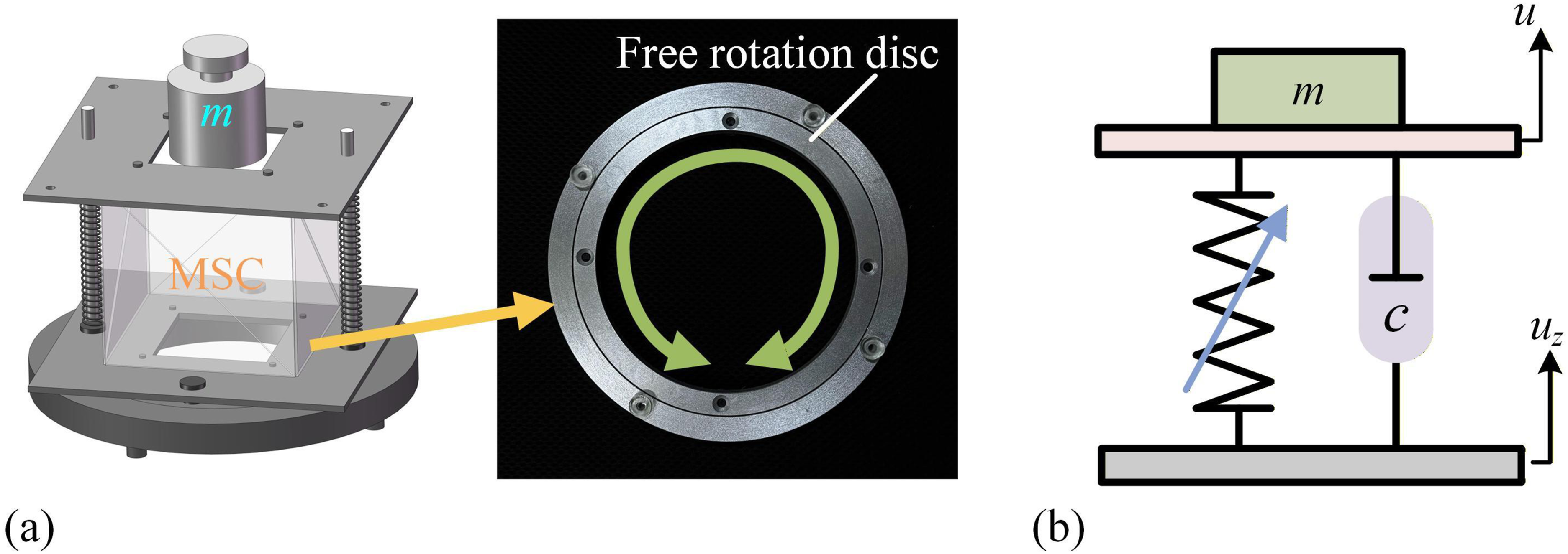
The kinetic energy of the isolation system comprises the rotational kinetic energy of the rotation disc and the absolution translational kinetic energy of the mass, given as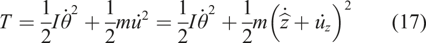
It can be further derived that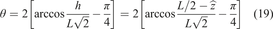
The dynamic model of the system is established by Lagrange’s equation. Defining the Lagrange function as L = T−V, the Lagrange’s equation is written as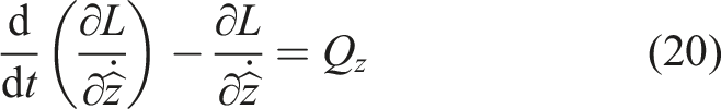
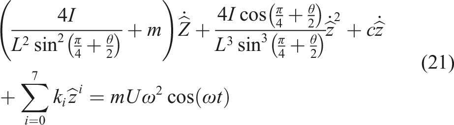
This equation comprehensively characterizes the nonlinear forced vibration response of the MSC origami-based isolator under base harmonic excitation, thereby providing a theoretical foundation for subsequent frequency response analysis, stability studies, and optimization of vibration isolation performances. The damping coefficient c will be identified from the experimental response, encompassing various dissipation mechanisms. This value is used to quantify the system’s energy dissipation, without explicit separation of its individual sources.
3.2. Vibration responses and displacement transmissibility
Since the force-displacement relation is asymmetrical at equilibrium, the steady-state response must contain a static offset A0, superimposed with different orders of harmonic components. Only considering the basic harmonic components, we can give the solution expression as
By substituting the above solution expression into the original governing dynamic equation (21), the equilibrium equations for both constant term and the fundamental harmonic component can be obtained. The static offset term A0 and harmonic term A must satisfy the balance conditions. Substituting solution (22) into dynamic model (21), constant terms should satisfy the following equation as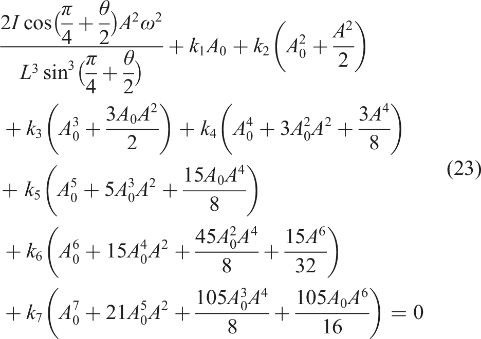
The equation for the fundamental harmonic component can be expressed as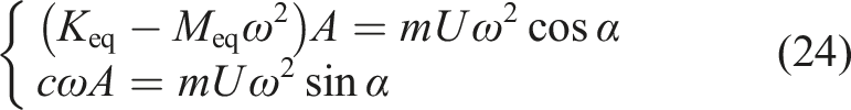
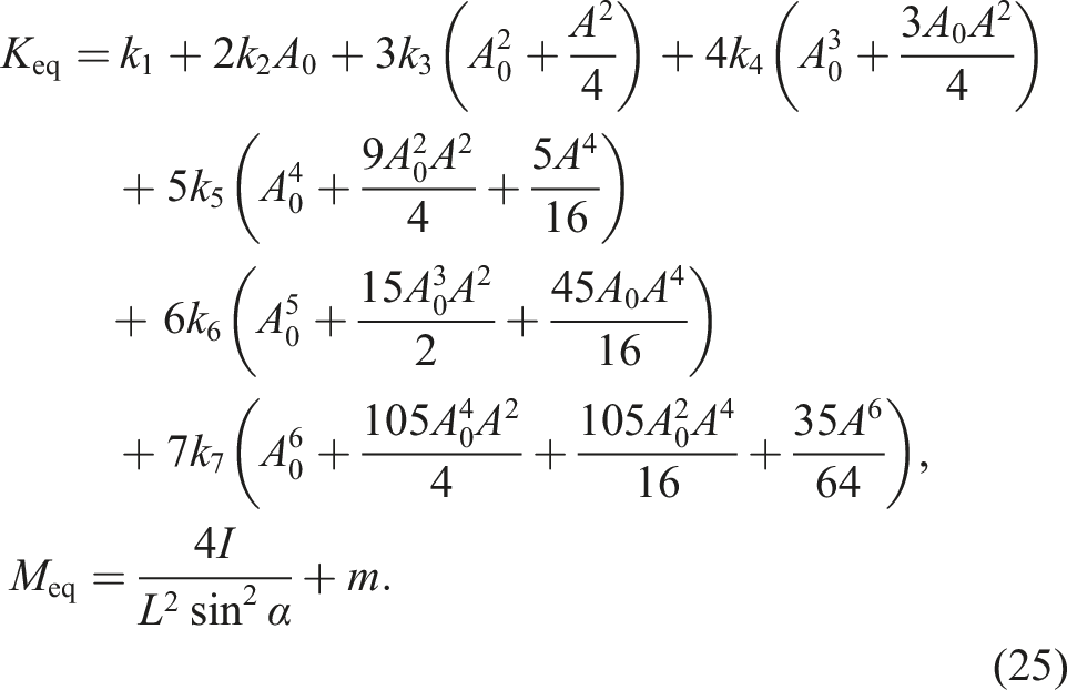
Due to the condition cos2α+sin2α = 1, the second harmonic balance equation can be obtained by equation (24). The displacement transmissibility, evaluating vibration isolation performance, is defined as the ratio of the absolute displacement amplitude of the top plate to the base excitation amplitude, given as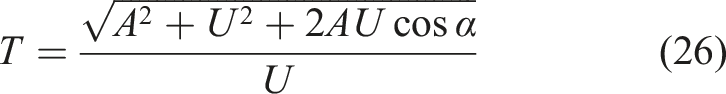
According to equation (26), the displacement transmissibility for different excitation amplitudes in frequency domain is shown in Figure 8. (a) Displacement transmissibility for different excitation amplitudes on frequency domain; (b) the initial frequency of the effective isolation band for different excitation amplitudes.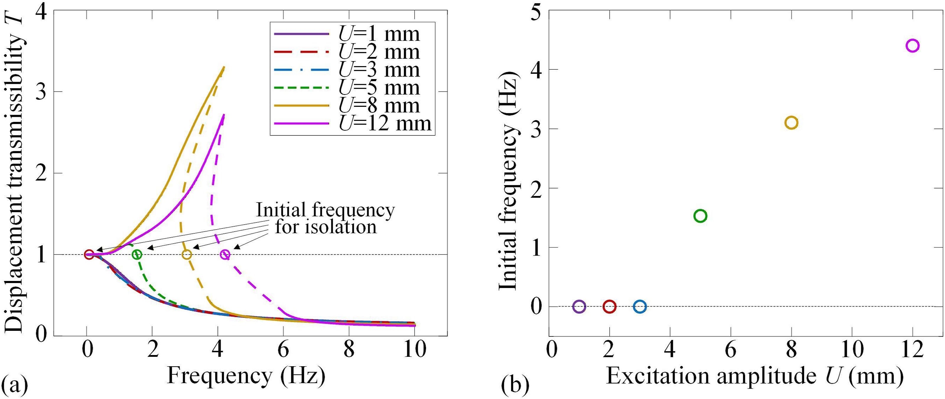
The results demonstrate that the MSC origami-based isolator can provide full-frequency domain vibration isolation as the excitation amplitude below 5 mm. Then, as the excitation amplitude U increases, the initial frequency for vibration isolation increases since the resonance frequency of the system would increase due to nonlinearity.
4. Experiment of the MSC origami-based isolator for full frequency vibration isolation
In the above sections, the force-displacement relationship of the MSC origami structure shows negative stiffness property due to multi-stable states induced by virtual creases, and the design criteria for wide-range QZS property has been carried out. From the theoretical displacement transmissibility results, it demonstrates that the MSC origami-based isolator exhibits full-frequency effective vibration isolation for a range of excitation amplitude. To further validate these theoretical findings, this section would propose experiment to verify the design of the MSC origami-based vibration isolator as Figure 9. The sample unit is MSC origami structure with side length of 60 mm with thin plates. In the theoretical analysis for comparison, the geometric thickness is neglected. As shown in Figure 9(a), the top and bottom surfaces of the MSC origami structure are fabricated by acrylic plates with 5 mm thickness, while the four side surfaces are fabricated by PET thin plates with 0.2 mm thickness. PET material was selected for its high flexibility and fatigue resistance, enabling the side surfaces to undergo out-of-plane deformation under compression (as shown in Figure 2) while maintaining overall structural stability. This characteristic is essential for the formation of virtual creases and the realization of QZS properties. And thus, the top and bottom plates are considered as rigid body since they have much larger stiffness than the side surfaces, each equipped with two centrally symmetric circular holes to accommodate two rigid smooth rods. Two linear springs with pre-calibrated stiffness are mounted between the top and bottom plates. Due to the rotary table assembled at the bottom plate, it ensures that both the MSC origami structure and springs do not undergo torsional deformation during the axial direction loading and vibration isolation. The top rigid plate has a dedicated area designed for placing loading in the axial direction. Design schematic of the MSC origami-based vibration isolator.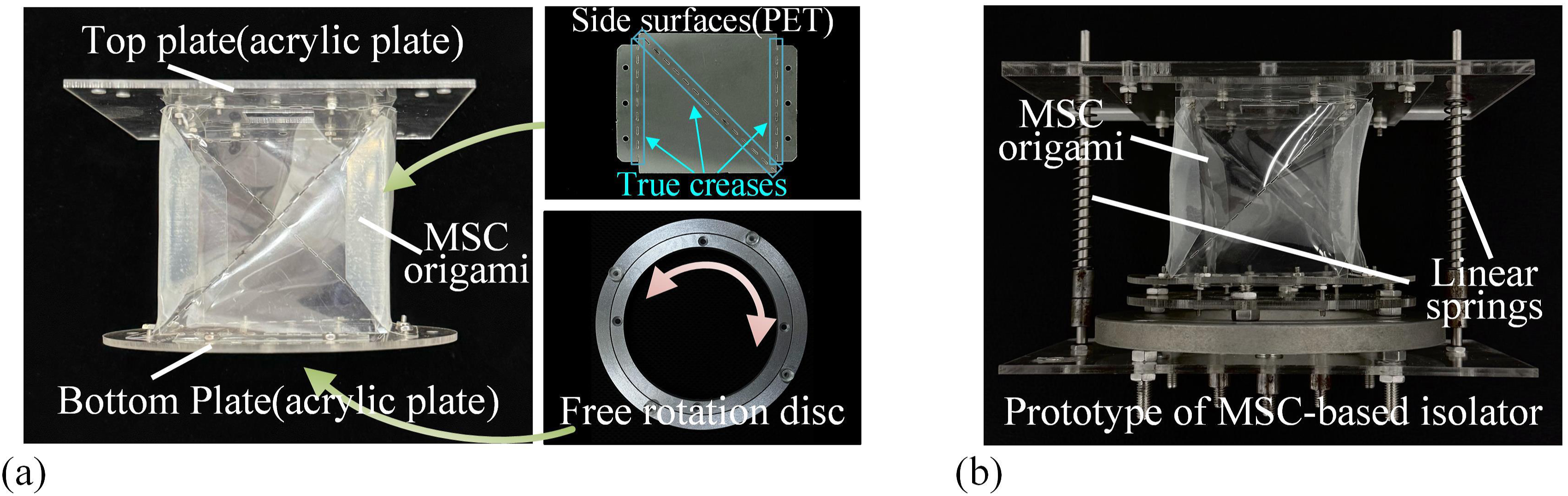
In order to obtain the desired isolator with full-frequency vibration isolation, the testing for MSC origami structure, springs and isolator is proposed. First, the force-displacement of true creases in the MSC origami structure can be obtained as Figure 10(a), where it discovers that the equivalent stiffness is linear. Thus, the force-displacement and dynamic stiffness of the whole MSC origami structure can be predicted by theoretical modeling. And then, the pre-deformation of springs can be fixed according to the required positive stiffness based on the testing shown in Figure 10. Finally, the MSC origami-based isolator has wide-range QZS property as shown in Figure 10(a) and (b). Quasi-static testing to obtain stiffness values of creases, springs and the constructed MSC-based isolator.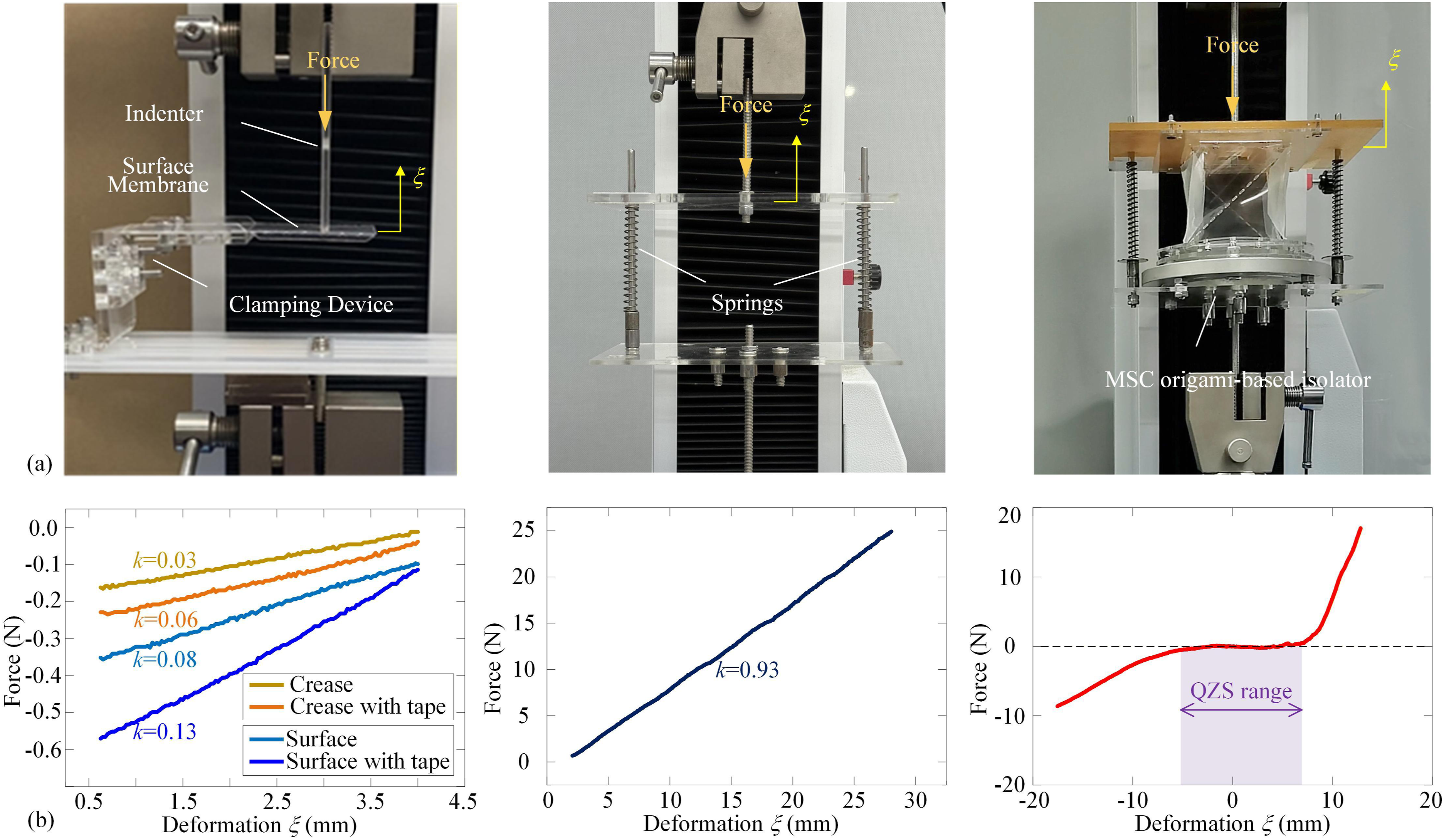
To evaluate the vibration isolation performance, low-frequency vibration experiment is conducted. The MSC origami isolation structure, equipped with a linear spring and a mass block, was mounted on a shaker. The shaking table was driven and controlled by a vibration control system, operating in a fixed-frequency mode with an excitation frequency range of 1–10 Hz with a constant amplitude fixed at ±2 mm. Retroreflective markers were attached to both the base platform and the top surface of the isolation structure to ensure vertical laser alignment and adequate signal strength. Two laser vibrometers were used to synchronously acquire vibration signals: one monitored the base input displacement, while the other measured the structural response displacement. Prior to formal testing, system calibration was performed, including unloaded pre-vibration to verify the control accuracy of the base platform and to eliminate interference from unintended degrees of freedom. The formal test started at 1 Hz with a frequency step of 0.5 Hz. At each frequency point, the excitation was maintained for 20 s, and the steady-state data from the last 10 seconds were extracted for processing Figure 11. Low-frequency vibration isolation experiment of the MSC origami-based vibration isolator.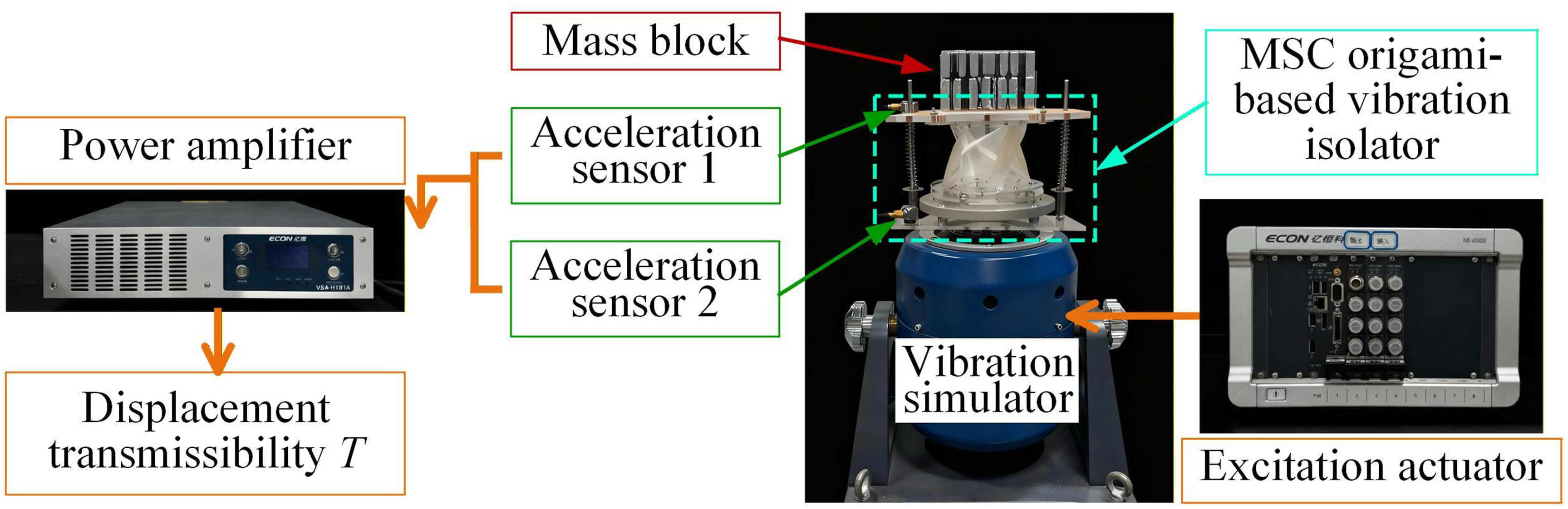
The displacement amplitudes at measurement points A and B are extracted via Fourier transform, and the displacement transmissibility was calculated as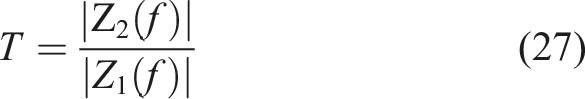
The resulting transmissibility-frequency curve is plotted to analyze the system’s vibration isolation performance, as shown in Figure 12(a). The displacement transmissibility curve illustrates a comparison between the theoretically predicted and experimentally measured transmissibility of the MSC origami isolation system. The red lines represent the transmissibility derived from the theoretical model, with its damping coefficient identified from experimental data. The curve decreases smoothly with increasing frequency, reflecting typical vibration isolation characteristics in the frequency domain and demonstrating effective isolation performance in the low-frequency region. The black lines correspond to experimental measurements, which are distributed closely around the theoretical curve, indicating good agreement between theory and experiment. Low frequency deviations may stem from damping mechanisms such as turntable resistance, guide-rod friction, material internal friction, contact friction, and air resistance. Nevertheless, the model remains effective in predicting isolation performance on a global scale, confirming the feasibility of the QZS property. Future research efforts will be dedicated to establishing a more accurate nonlinear damping model, enabling finer predictions of low frequency, large amplitude responses and thereby supporting the optimal design of isolators. The transmissibility values remain consistently below 0 dB across the entire frequency band and stabilize within a relatively low range of approximately −10 dB to −12 dB in the high-frequency region from 4 Hz to 10 Hz, demonstrating excellent low-frequency vibration isolation performance of the system. The experimental data show good overall agreement with the theoretical curve, clearly reproducing the decaying trend of transmissibility with increasing frequency. Testing was not extended below 1 Hz due to equipment limitations. These comparative results thoroughly validate the accuracy and reliability of the proposed theoretical model, while concurrently confirming the effectiveness of the MSC origami structure as a vibration isolation device for low-frequency applications. (a) Displacement transmissibility results compared from theoretical analysis and experiment for 2 mm excitation amplitude; (b) comparison with other origami-based vibration isolators.
Figure 13 displays the displacement response time-history curves under sinusoidal excitations at three distinct frequencies at amplitudes of 1 mm, 2 mm, and 5 mm. Overall, as the frequency increases, the suppression effect of the vibration isolation control on the displacement response becomes progressively more pronounced, consistent with the theoretical expectation of reduced transmissibility in higher frequency ranges for isolation systems. Furthermore, the smaller the excitation amplitude, the better the vibration isolation performance, aligning with the theoretical model. Under large amplitude excitation, the nonlinear inertial term of the system becomes significantly enhanced, potentially inducing complex nonlinear resonance behavior that may, in turn, compromise the vibration isolation effectiveness. Notably, even under low-frequency conditions, the isolation system achieves significant vibration suppression, demonstrating the MSC origami isolator’s effective vibration control capability across a broad frequency band, particularly in the low-frequency regime. As shown in Figure 12(b), within the same frequency range, the MSC origami-based vibration isolator demonstrates superior load-bearing capacity and broader frequency bandwidth compared to other reported studies, exhibiting outstanding performance characteristics. Comparison of vibration isolation effectiveness for different excitation amplitudes with 1 mm, 2 mm, and 5 mm at different frequencies.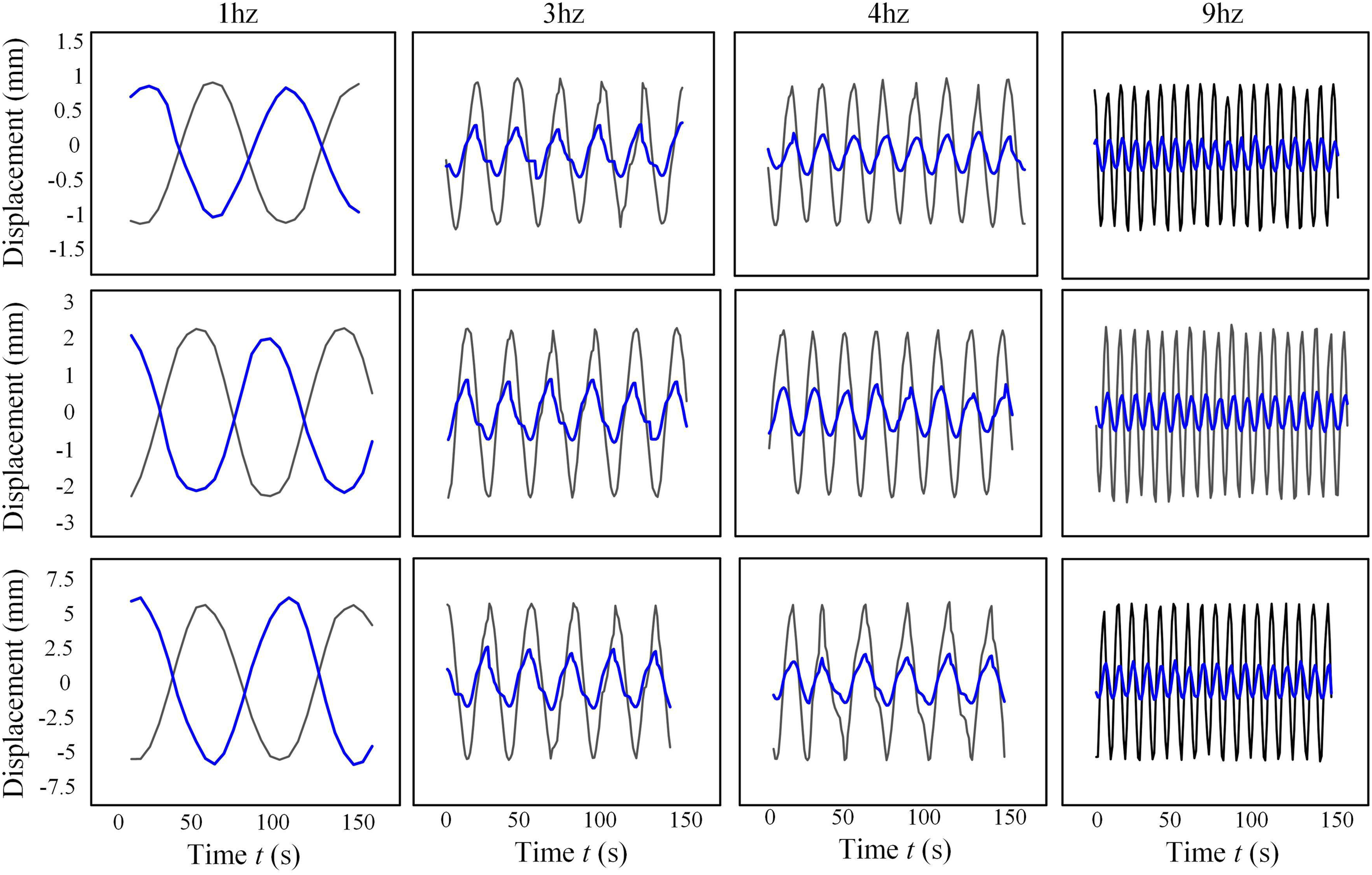
5. Conclusion
This study presents the design of a novel QZS vibration isolator based on MSC origami structure, which effectively breaks through the conventional limitation requiring the operating frequency of linear isolators to exceed √2 times the natural frequency of the system, thereby significantly enhancing full-frequency vibration isolation capability. By considering the virtual creases, this work provides new way to induce multi-stable states property, and thus, it obtains an adjustable negative stiffness structure. For appropriate structural parameters, QZS range reaches as wide as 20–25% of the deformable area rather than the previous QZS property, achieving full-frequency vibration isolation for a specific range of excitation amplitude. Furthermore, by integrating the prediction of elastic restoring forces with constant external loads, both low-frequency excitation and constant-force excitation are incorporated into the dynamic model as external excitations, thereby refining the nonlinear dynamic modeling of the system. Based on this theoretical framework, a unit cell prototype of the MSC origami structure is designed and fabricated. Systematic experiments, including material stiffness tests, tension-compression tests, and variable-stiffness characterization, are conducted. The experimental results demonstrate strong agreement with theoretical predictions, effectively validate the correctness and applicability of the theoretical model. These findings indicate that the MSC origami-based isolator holds significant potential for engineering applications in full-frequency domain, providing new perspectives for the design of high-performance low-frequency vibration isolators. This work offers valuable insights for applications in precision instrumentation, aerospace equipment, and other fields demanding advanced vibration control capabilities.
Footnotes
Funding
The authors disclosed receipt of the following financial support for the research, authorship, and/or publication of this article: The authors would like to gratefully acknowledge the support from the National Natural Science Foundation of China under grants (No. 12372022, U2441202, 12372043, 12532002) and Fundamental Research Funds for Central Universities.
Declaration of conflicting interests
The authors declared no potential conflicts of interest with respect to the research, authorship, and/or publication of this article.
Data Availability Statement
The datasets generated and analyzed during the current study are not publicly available but are available from the corresponding author on reasonable request.