






Abstract
Addressing stick-slip vibrations in drill string systems is critical in drilling operations, as these vibrations can cause costly downtime and equipment damage. A four-degrees-of-freedom (4-DOF) model captures the dynamics of long vertical drilling systems, followed by a robust tube model predictive control (MPC) strategy to account for system uncertainties. The controller is designed to handle variations in key parameters, such as drill pipe inertia—affected by pipe length—and weight on bit—affected by axial vibrations—without relying on direct bit velocity measurements. Comparative analysis with sliding mode control (SMC) demonstrates that the proposed MPC achieves substantially faster settling times and lower mean squared error (MSE). Specifically, for the top driver, the settling time is reduced by 41% and MSE by 74% compared to SMC. Relative to proportional–integral–derivative (PID), the tube MPC improves MSE by 69% and reduces settling time by 40%. In addition, the linear quadratic tracking (LQT) and linear MPC controllers were compared with the proposed method. A sensitivity analysis further evaluates the influence of parameter uncertainties, with simulation results confirming the controller’s effectiveness in suppressing stick-slip oscillations and maintaining robust performance under uncertain conditions.
1. Introduction
Vertical drilling systems are essential components in the exploration and extraction of subsurface resources, ranging from oil and gas to geothermal energy. Unlike conventional drilling methods, vertical drilling allows for the creation of deep, precise wells, directly penetrating target formations. This precision not only maximizes resource recovery but also minimizes environmental impact by reducing the surface footprint. Drilling is a critical process in accessing natural resources that power industries and fuel economies worldwide. Without efficient drilling techniques, resource extraction would be far more costly, time-consuming, and environmentally detrimental. A key factor in the efficiency of vertical drilling is the control system, which ensures that the drill bit remains on the intended path, even when encountering unpredictable subsurface conditions. Advanced control systems employ real-time data analysis and feedback mechanisms to adjust drilling parameters, such as rotational speed, weight on the drill bit, and mud flow rate. By maintaining the vertical trajectory, these systems reduce deviation, enhance well integrity, and optimize the overall drilling process.
In this article, we will explore the technical aspects of vertical drilling systems and delve into the role of modern control technologies in improving drilling precision and efficiency. By understanding these elements, we can better appreciate the engineering challenges and innovations that continue to push the boundaries of subsurface exploration.
Figure 1 presents a drill bit that consists of multiple parts, mainly a drill collar, drill pipes, a rotary table, and a drill bit. Whole drill string dynamic.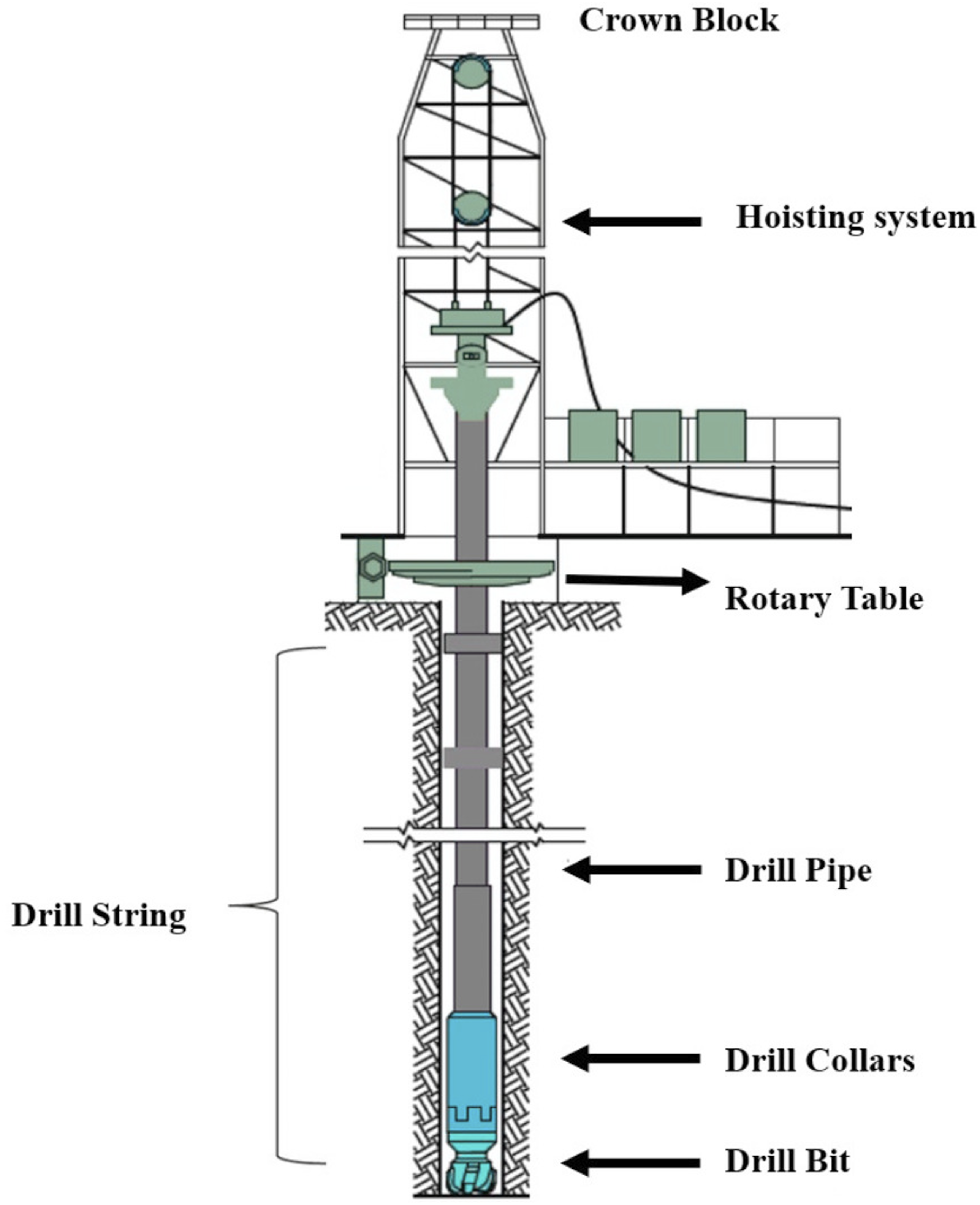
In modeling this phenomenon, several approaches are considered. Saldivar et al. (2016) introduce four model types: Lumped Parameter, Partial Differential Equation (PDE), Neutral Type model, and Coupled PDE-ODE (Ordinary Differential Equation). Each of these models has its advantages. The lumped parameter model offers simplicity in analysis and is commonly used. For instance, in Yigit and Christoforou (2006), robust pole placement is employed to stabilize the system. In Mihajlovic et al. (2004), an experimental setup is used with a discontinuous static friction model to predict vibrations, which is validated through numerical and experimental analyses. Tang et al. (2015) investigate the occurrence of stick-slip at various rotary speeds, concluding that this phenomenon occurs when the speed is below 127 RPM.
The PDE model provides high accuracy but requires complex analysis, and its precision depends heavily on boundary conditions. In Sagert et al. (2013), a backstepping control approach is proposed, while Wang et al. (2020) employ adaptive output feedback control, utilizing adaptive methods and infinite-dimensional backstepping to handle unknown disturbances and anti-damping terms. Simulations validate the controller’s effectiveness, significantly reducing torsional vibrations. Similarly, in Tashakori et al. (2021), a prediction-based control strategy is introduced to stabilize the axial-torsional dynamics of a distributed drill string system using an infinite-dimensional model and continuous pole-placement techniques based on top-side measurements.
The Neutral Type model simplifies system analysis, but its accuracy also depends on boundary conditions. Article Wu et al. (2020) were the first to use this model, applying a simple robust controller with equivalent input disturbances. The Coupled PDE-ODE model facilitates the design of control strategies but is suitable only for specific strategies.
Two additional models exist. The first is the simplified wave model, which uses two first-degree PDEs instead of one second-degree wave equation. In Aarsnes et al. (2019), this model is used with an optimal controller via extremum seeking, and in Aarsnes and Shor (2018), presented a distributed model of a drill string to investigate torsional vibrations when the bit is off bottom. It characterizes the stick-slip limit cycle caused by distributed Coulomb friction and validates the model with field data from deviated wells. The study finds a close match between recorded and modeled data, highlighting the model’s effectiveness. In Aarsnes and Van de Wouw (2018) analyzed the stability of distributed drill string systems by deriving a minimal set of parameters for their axial-torsional dynamics. It uses these parameters to create stability maps, revealing complex dynamics not evident in lumped models. The findings aid in designing control strategies to mitigate vibrations 12 The second is the finite element method using spring-damper elements, where the number of spring-dampers represents the system’s degrees of freedom. The simplest version, a 2-DOF model, is explored in Yan et al. (2023), where a PID controller is presented, and in Monteiro and Trindade (2017), where a PI controller is implemented. Various bit-rock interaction models for this method will be discussed in the modeling section. In Chen and Allgöwer (1998), an LQG controller is implemented, showing that LQG offers a smoother response compared to H ∞ control for structured disturbances. In Doghmane et al. (2022), an H ∞ controller is introduced, demonstrating better performance in rejecting unstructured disturbances. Mayne et al. (2000) propose a dual-loop controller with an outer loop for fast response and an inner loop for damping vibration. Other controllers, such as the modified integral resonant controller (MIRC), are compared with sliding mode controllers (SMC) in MacLean et al. (2021), while Aarsnes et al. (2021) compare nonlinear model predictive controller (NMPC) with ZTorque, claiming that ZTorque has better performance.
A 3-DOF model is used in Mendil et al. (2021), which compares four controllers (PI, PID, Hybrid PI, and Hybrid PID), showing stabilization within 10 seconds. A new cascade sliding mode control architecture is proposed in Ghasemi and Song (2017). A 4-DOF model is explored in Talbi et al. (2023), where an optimal hybrid fractional-order fuzzy logic controller is compared with PID, fractional-order PID, and SMC. In Huang et al. (2024), a fuzzy comprehensive evaluation method is proposed to identify bit-rock interaction, while Fouad et al. (2011) propose an SMC to reduce top-driver motor effort. Sadeghimehr et al. (2021) introduce an SMC with a Smith predictor, and Huang et al. (2018) compare the fourth-fifth order Runge-Kutta method with field data. Article Van Veggel et al. (2015) propose robust output feedback, and in Laib and Gharib (2024) proposed cascade feedforward neuro-fuzzy PID control for this system.
Some articles, such as Xie et al. (2022), do not specify the model explicitly but propose three architectures for active stick-slip vibration control. In others, like Cheng et al. (2020), more than 4-DOF models are used, with Cheng et al. (2020) employing a 20-DOF model and a gain-scheduled controller for control. The conventional controllers face several limitations: • • •
To cope with these limitations Tube MPC controller designed and, the main contributions of this article are as follows: • • • •
In this article, the spring-damper model is employed and uncertainties in inertia are considered to address unstructured disturbances. This is achieved by implementing a robust model predictive controller (MPC) that accounts for uncertainties. In the following sections, we present our model, explore the interaction between the rock and bit, and finally, propose the controller, demonstrating its performance through simulations.
2. The mathematical model
2.1. Drill string model
Figure 2 at the top is the top drive inertia, J
r
, followed by the equivalent elements for drill pipes, J
p
, drill collars, J
l
, and the bit inertia, J
b
. In this model, the torsional stiffness of the springs is represented by k
rp
, k
ph
, and k
hb
, and torsional damping by b
rp
, b
ph
, and b
hb
. The angular displacement and angular velocity of each element are denoted as θ
i
and 4-DOF drill string model.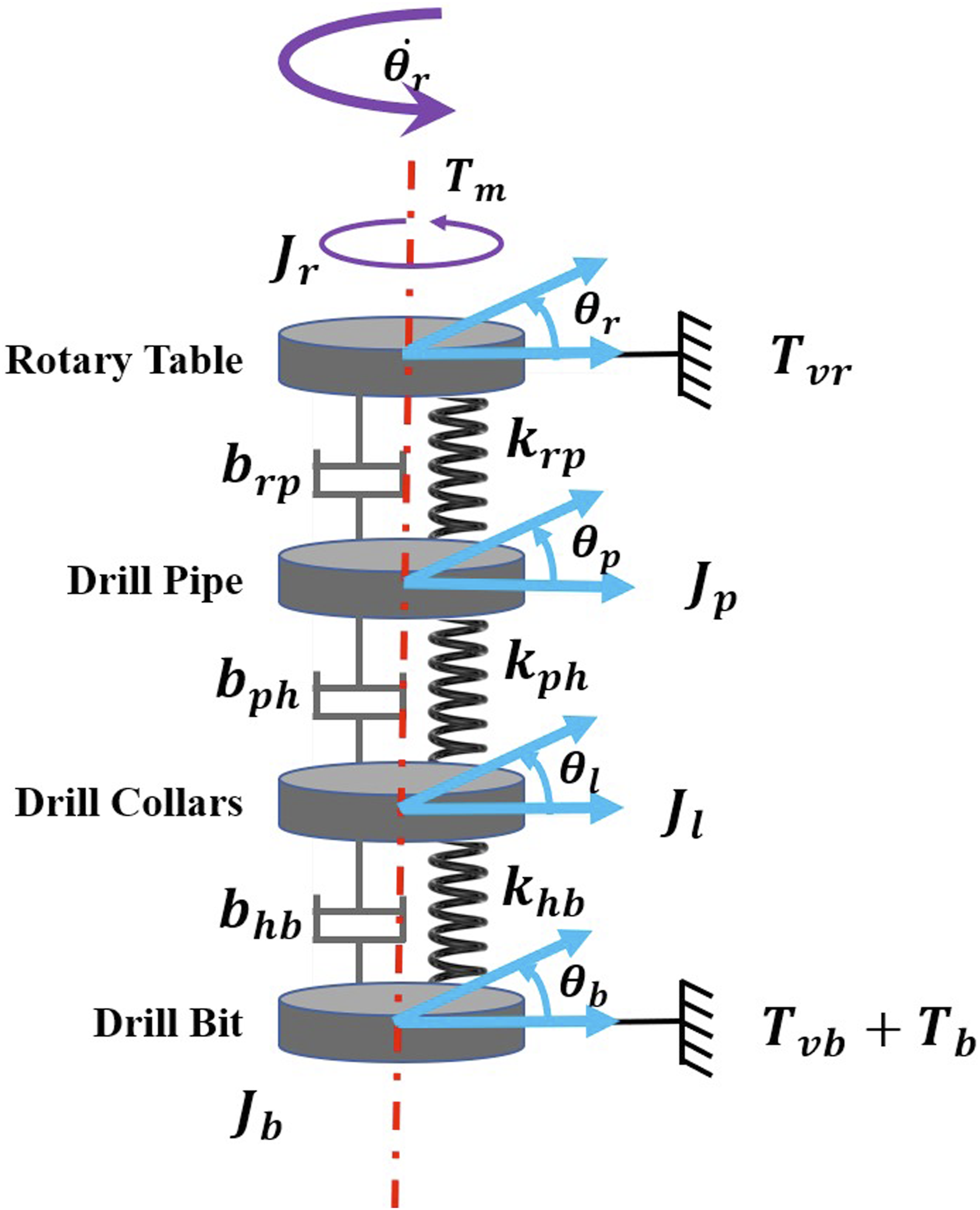
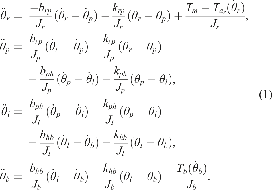
2.2. Bit-rock interaction
Models like Simscape, Karnopp’s model, and the Coulomb friction model enable realistic simulations of bit-rock interactions in drilling. Simscape modeling in MATLAB aids in optimizing bit design, predicting drilling performance, and refining control strategies, supporting risk assessment and operator training through virtual testing. Karnopp’s model introduces exponentially decaying friction, while the Coulomb model captures torque dynamics by simulating transitions between static and dynamic friction—both essential for understanding drill-bit behavior in complex drilling environments.
2.3. Simscape modeling
In some articles, such as Chen and Allgöwer (1998) and Doghmane et al. (2022), the model is implemented using Simscape, as shown in Figure 3. Simscape modeling of bit-rock interaction in MATLAB enables realistic simulations that optimize bit design, predict performance, and enhance control, improving safety, efficiency, and cost-effectiveness in drilling. Bit-rock interaction in Simscape Chen and Allgöwer (1998).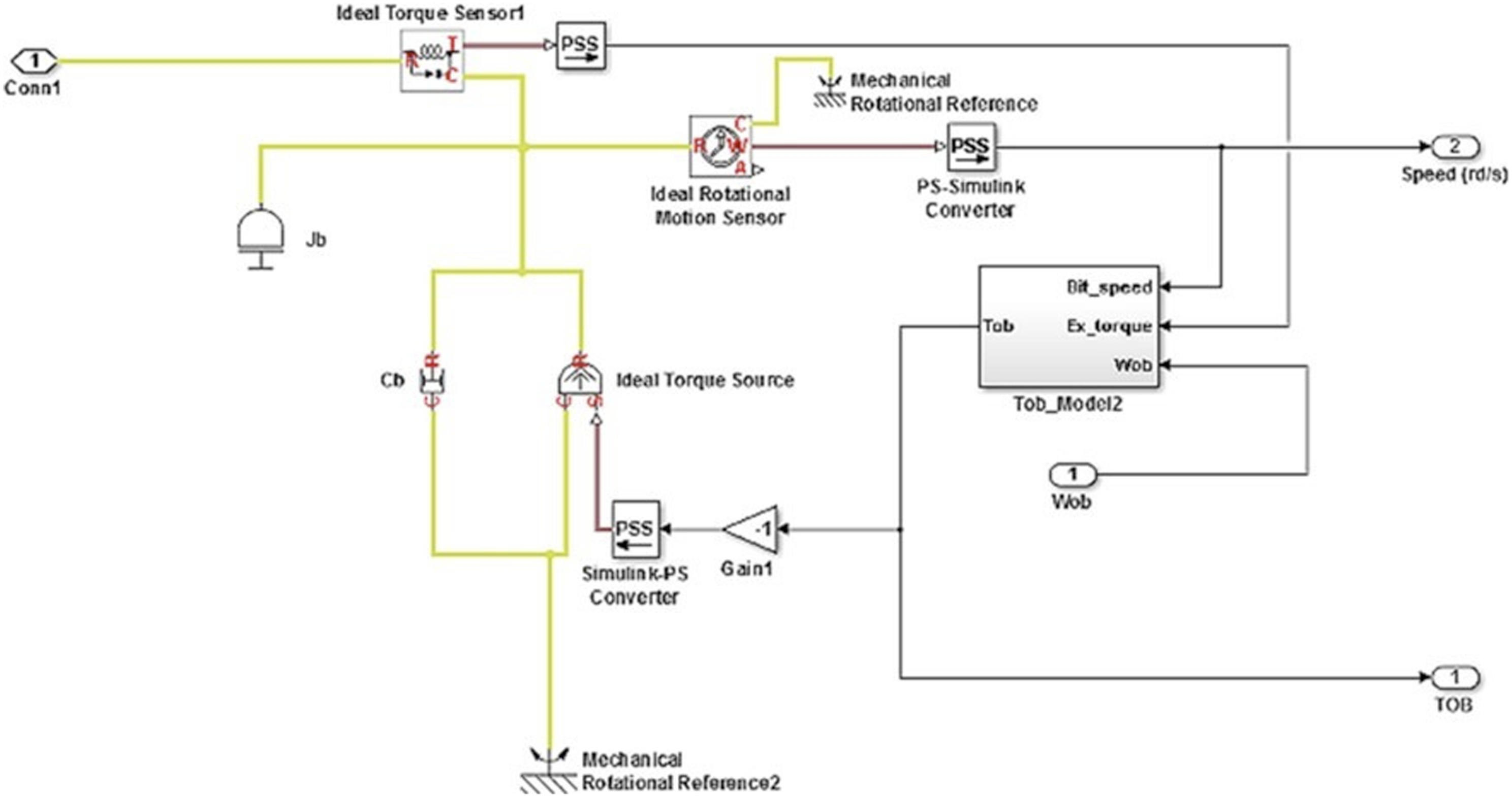
2.4. Karnopp’s model
This method includes an exponentially decaying friction term, as shown below:

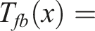

The parameters in this equation describe the forces and conditions influencing torque during bit-rock interaction in drilling. T
fb
(x) represents the frictional torque at the bit, and T
eb
(x) is the elastic torque caused by the deformation of the drill string. The rotational velocity of the bit,
Coulomb friction model: This equation characterizes the torque generated by the interaction between the drill bit and the rock using an adapted Coulomb friction model as follows:


The key variables include the rotational velocity of the bit,
2.5. Tube MPC
Tube Model Predictive Control (MPC) has emerged as a groundbreaking approach within control theory, addressing the challenges of uncertainties in dynamic systems with novel strategies. Its core principle involves wrapping the predicted system trajectories within a “tube,” offering a robust shield against disturbances and model imperfections. This tube-based strategy not only enhances resilience against external factors but also ensures a level of guaranteed performance within a restricted zone around the nominal path. More than just stabilizing the system, Tube MPC supports optimal performance in the presence of uncertainty, redefining the boundaries of modern control strategies.
As optimization methods advance, Tube MPC continues to play a leading role in precision-driven and adaptive control solutions, finding applications in industries ranging from aerospace to automotive. Its innovative framework paves the way for the next generation of control systems, merging cutting-edge theory with real-world application. The associated cost function can be expressed as:

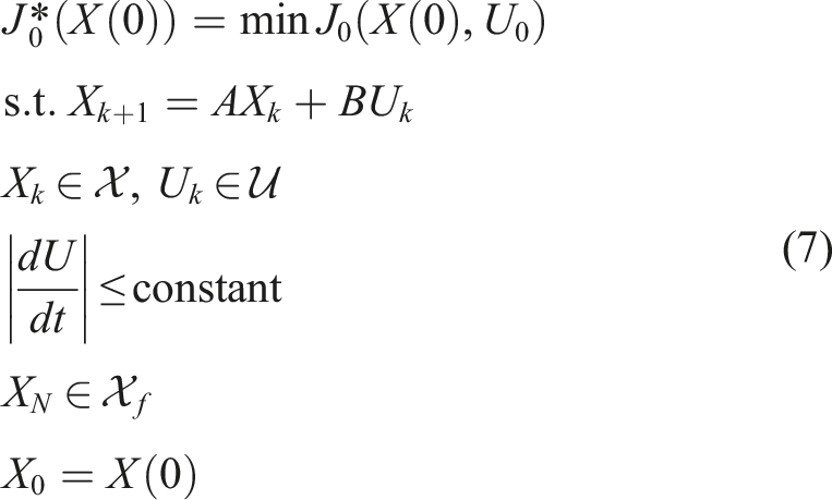
Here, N represents the control horizon, and the sets
Tube MPC offers significant advantages over LQG and SMC for control of complex and constraint-limited systems such as drilling rigs. As a robust control strategy, Tube MPC explicitly accounts for bounded disturbances and incorporates both state and input constraints directly into its optimization framework. In contrast, neither LQG nor SMC inherently supports constraint handling, which limits their applicability in safety-critical systems where operational bounds must be strictly respected. SMC, while robust to matched uncertainties, suffers from the well-known chattering phenomenon, which can induce mechanical wear and excite unmodeled dynamics in drilling equipment. Moreover, SMC focuses primarily on driving the system to its sliding surface without predictive capabilities or multi-objective optimization, resulting in suboptimal performance in applications requiring both robustness and efficiency. LQG, although optimal in the linear quadratic sense under Gaussian noise assumptions, is sensitive to modeling inaccuracies and lacks explicit mechanisms to handle physical constraints. In contrast, Tube MPC not only maintains robustness but also enables simultaneous optimization of performance objectives—such as minimizing torsional vibration, improving rate of penetration, and reducing energy consumption—while guaranteeing constraint satisfaction. Its predictive nature allows it to anticipate future disturbances and adjust control inputs proactively, resulting in smoother actuator commands and reduced mechanical stress compared to the discontinuous control actions typical of SMC. These combined features make Tube MPC a superior choice for high-value, safety-critical systems where both robustness and performance optimization are paramount.
2.6. Stability and feasibility analysis
In this section, the control policy v, using feedback gain K, is designed to keep the actual system trajectory close to the nominal trajectory, aiming to meet system constraints while tracking a reference. Key assumptions include bounded disturbances within a convex set, controllability of the system, and accessible state measurements. The system’s error dynamics—defined as the deviation between actual and nominal states—are contained within a robust positively invariant (RPI) set, which forms a “tube” around the nominal path. Stability and recursive feasibility are ensured through conditions that maintain bounded state trajectories over time. Supporting lemmas confirm recursive feasibility when the cost function is initially feasible, and stability is achieved by a local stabilizing controller within a defined terminal region. Stability of the closed-loop system is further supported by a Lyapunov inequality involving the weight matrices Q, R, and an augmented cost matrix Q*, which collectively guarantee system performance and stability.
2.6.1. Nominal plant
The nominal disturbance-free system is described:

2.6.2. Assumption 1
The dynamics of the system can be described as follows:


2.6.3. Assumption 2
Disturbance ω belongs to a closed, bounded, and connected set (convex polyhedron):

2.6.4. Assumption 3
The control policy v can be defined as follows:


2.6.5. Assumption 4
The pair (A, B) is controllable,and the state of the system is known at each sample time.
Control Input: According to assumption 3, the control input can be designed as follows:

The error of the system can be defined as:

By substituting 1 and 8 in 15, the error between the nominal and disturbed plant is given by:

If the feedback control gain K is chosen in a way that matrix (A + BK) is Hurwitz, then the evolution of the error term e
k
remains bounded. Consequently, the actual trajectory x
k
will reside in a neighborhood around the predicted trajectory
2.7. Bound maximum error
As per control theory, it becomes evident that there exists a set ɛ such that the error term e
k
remains within it indefinitely. If the set ɛ is robustly positively invariant (RPI) for the system equation (16), and the initial conditions x0 and
Controlled by equation (14) ensures that
A set ɛ is considered a robust positively invariant (RPI) set for the uncertain system equation (11) if the matrix product (A + BK) remains bounded by the matrix (A + BK)ɛ ⊕Ω ⊆ɛ.
2.8. Recursive feasibility and closed-loop stability
Ultimate Boundedness refers to a property of a closed-loop system where the trajectories of the state variables remain bounded over time, regardless of the initial conditions. This property is essential for ensuring the stability of feedback control systems. When a system is ultimately bounded, it guarantees that the state variables do not escape to unbounded regions, even if disturbances or uncertainties are present.
For conventional Tube MPC, the following lemma establishes a foundational theoretical framework to guarantee both recursive feasibility and closed-loop stability. This lemma serves as a cornerstone for understanding the robustness properties of MPC, ensuring that feasible control inputs are always available while maintaining long-term stability of the closed-loop system.

Recursive feasibility of MPC for the linear model is guaranteed if there exists a feasible solution for the cost function at k = 0.
Consider a local stabilizing controller
Furthermore, if the controller

3. Simulations and results
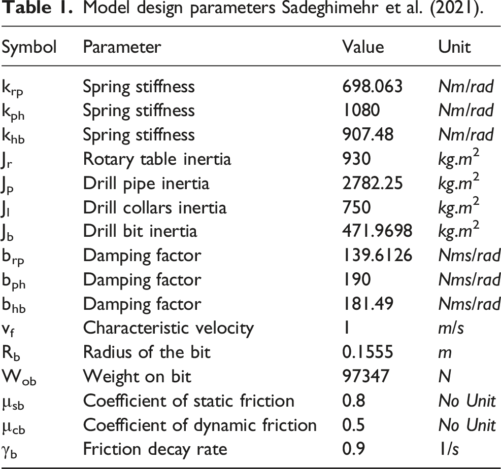
Model design parameters Sadeghimehr et al. (2021).
3.1. Assumption
• In these simulations, all states are assumed to be measurable. For a noisy system, however, a Luenberger observer or a Kalman filter can be designed using measurements of the rotary table position and velocity.
3.2. Manual control
In this control method, a constant input of 30,000 is applied to the drill-bit system. As shown in Figure 4, the system becomes stuck due to torsional vibrations, causing all velocities to converge to zero. Velocity of the top driver and drill bit under manual control with an input torque of 30,000 N⋅ m.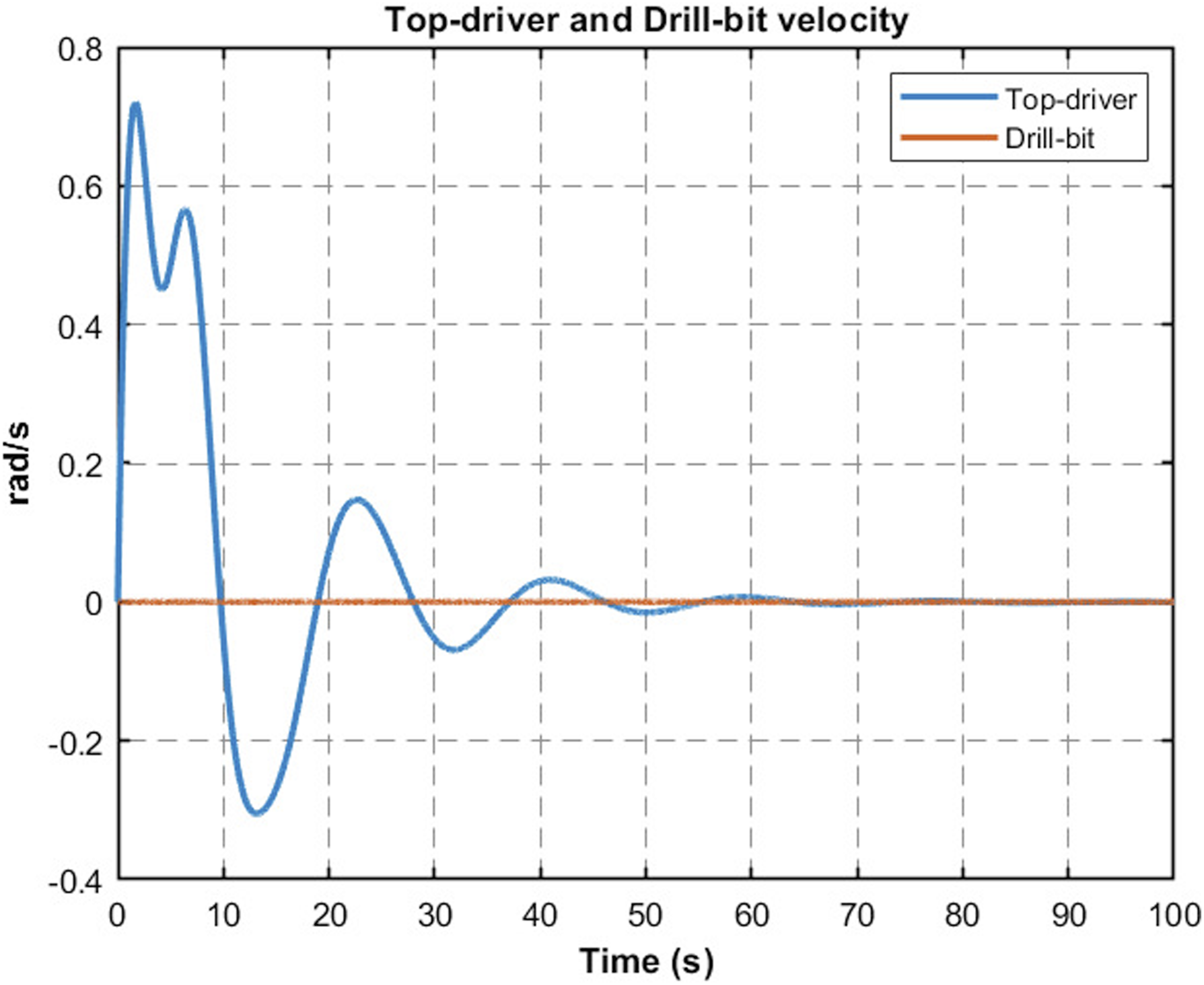
3.3. Tube MPC, SMC, and PID controllers
For designing these controllers, the following assumptions are considered: • All states are assumed to be measurable. • No measurement delay is considered. • The top driver velocity is constrained to remain non-negative during control for Tube MPC.
In this section a normal Tube MPC with the following constrains considered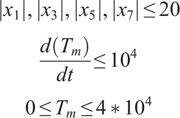
For the SMC controller, the input proposed in Sadeghimehr et al. (2021) has been used.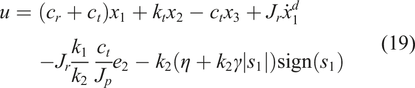
Since the controller was originally tuned for an input delay system, it did not provide a satisfactory response with the parameters used in the referenced article. Therefore, the parameters were refined to achieve a better response. The updated parameters are as follows:

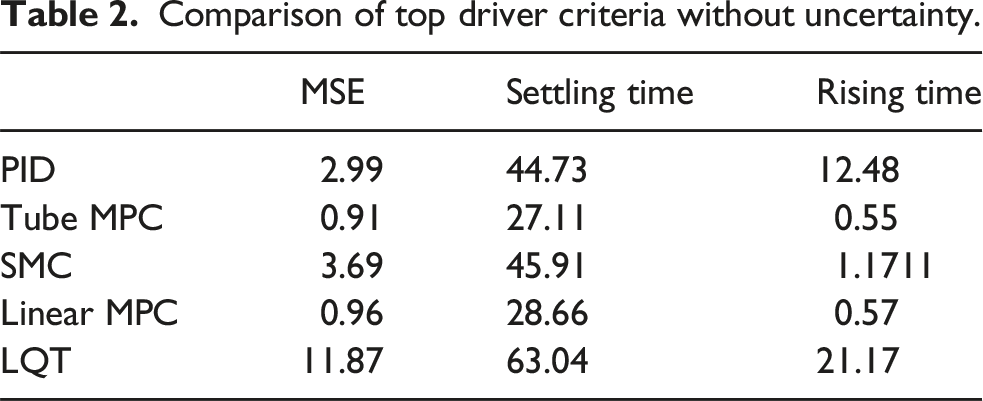
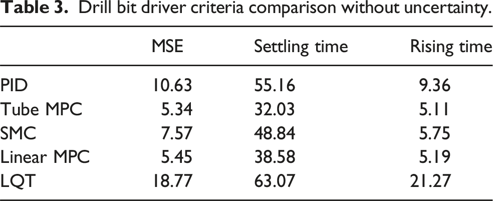
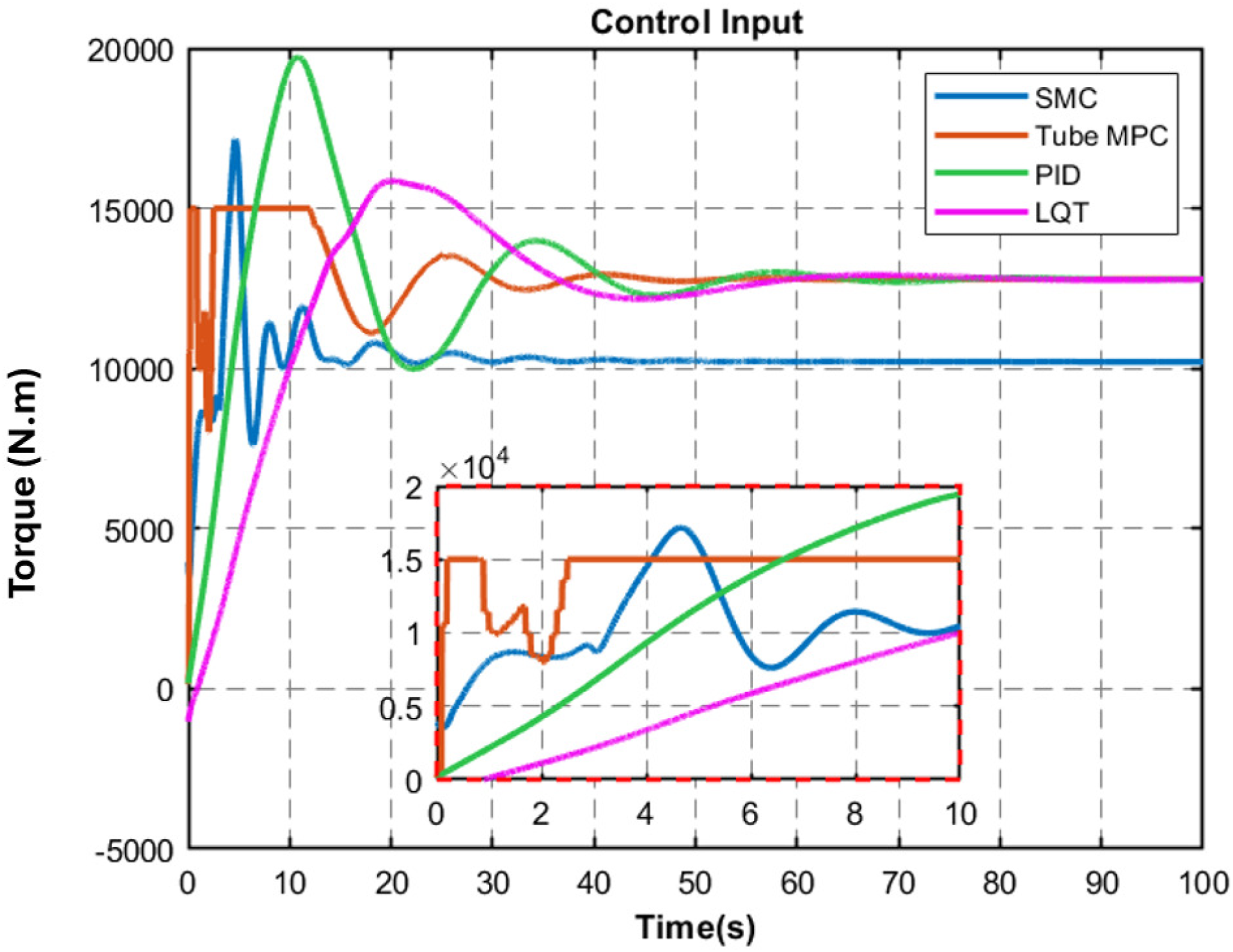
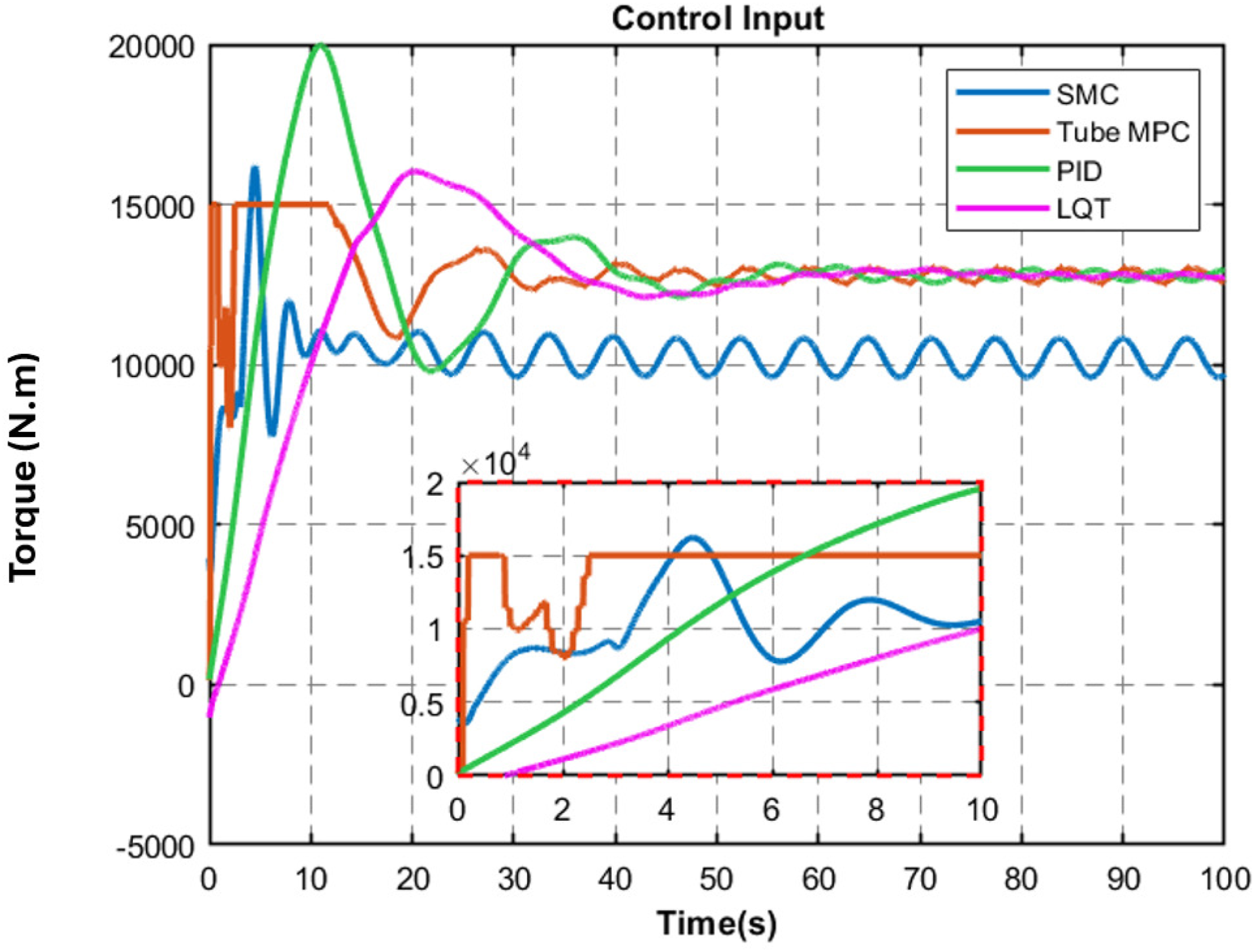
Based on the results presented in Figure 5 and summarized in Tables 2 and 3, the proposed controller demonstrates superior performance by achieving reduced MSE, shorter settling time, and faster rise time compared to alternative control strategies. Moreover, as illustrated in Figure 6, the PID and SMC controllers generate higher magnitude control inputs, indicating their inability to adhere to actuator constraints. Notably, the PID controller also exhibits pronounced overshoot in the drill bit velocity response, which is undesirable from a performance standpoint. Comparison of Tube MPC, SMC, PID, and LQT controllers without uncertainties. (a) Comparison of top driver velocity performance of controllers in the absence of system uncertainty; (b) Comparison of the Bit angular velocity performance of controllers in the absence of system uncertainty. Comparison of top driver criteria without uncertainty. Drill bit driver criteria comparison without uncertainty. Comparison of control inputs for tube MPC, SMC, PID, and LQT controllers without uncertainties.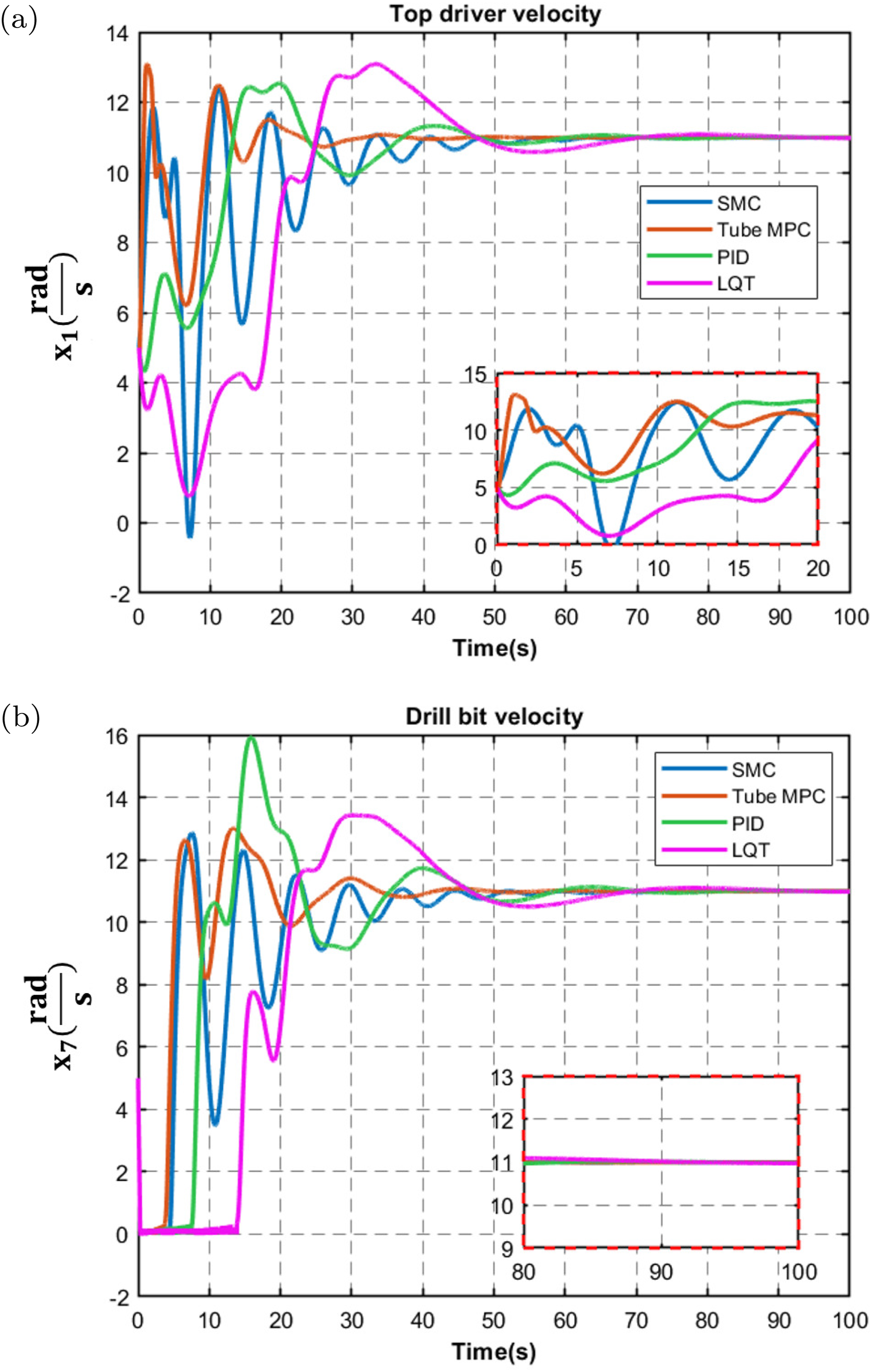
3.4. J p uncertainty
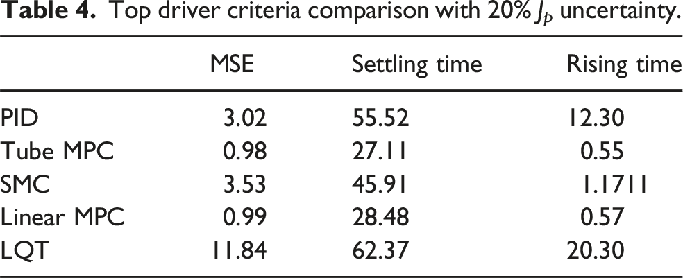
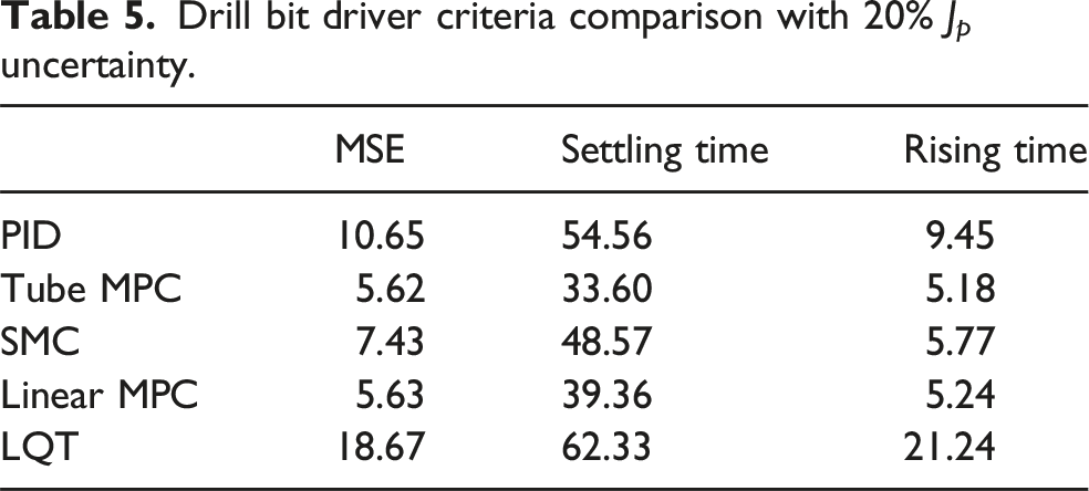
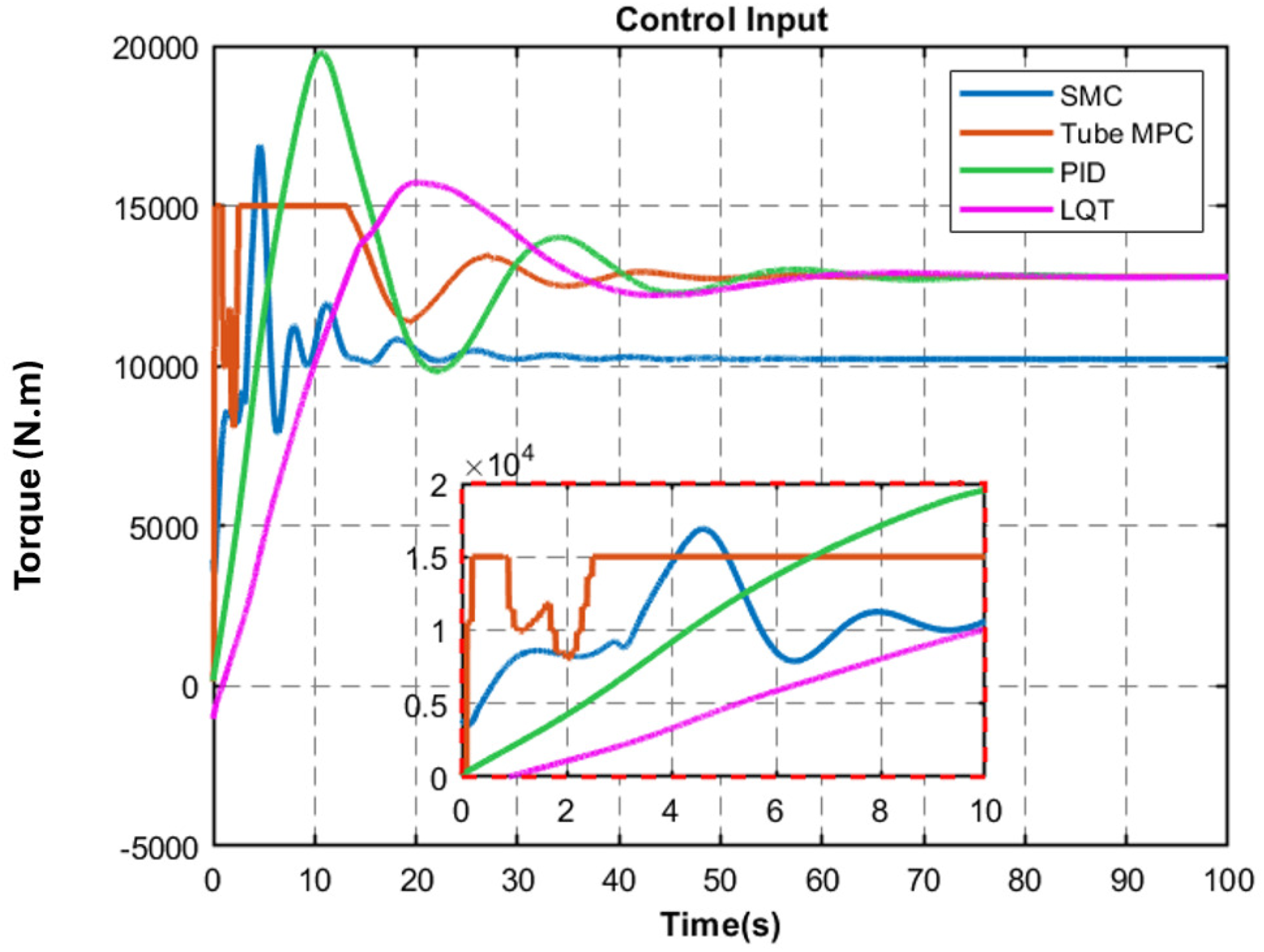
Based on Figure 7, the control performance criteria presented in Tables 4 and 5 are very close to those obtained in the nominal (uncertainty-free) case. Moreover, the proposed controller achieves a lower MSE, as well as shorter rise and settling times, compared to the other controllers. Additionally, as shown in Figure 8, similar to the previous section, the PID controller exhibits a significantly larger overshoot than the other controllers. Comparison of Tube MPC, SMC, PID, and LQT controllers with 20% uncertainty on J
p
. (a) Comparison of top driver velocity performance of controllers with 20% uncertainty on J
p
; (b) Comparison of the Bit angular velocity performance of controllers with 20% uncertainty on J
p
. Top driver criteria comparison with 20% J
p
uncertainty. Drill bit driver criteria comparison with 20% J
p
uncertainty. Comparison of Control Inputs for Tube MPC, SMC, PID, and LQT Controllers with 20% uncertainty for J
p
W
ob
uncertainty.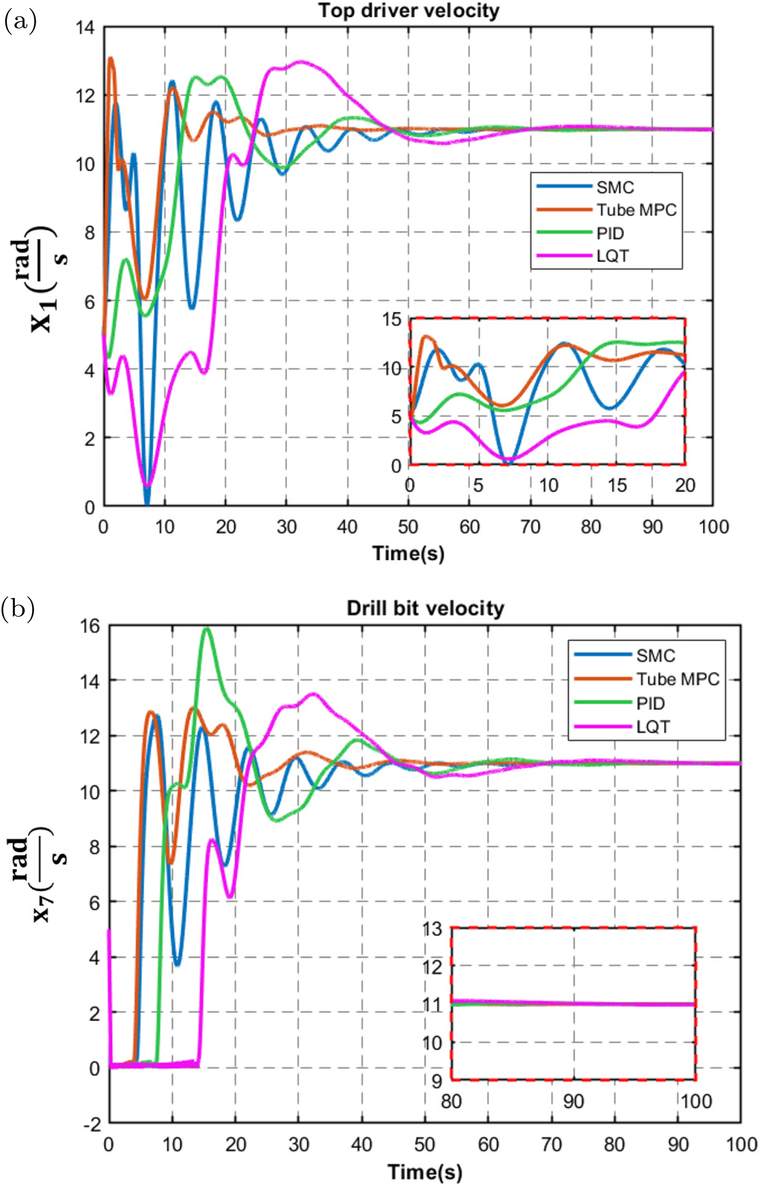
3.5. MPC parameters tuning

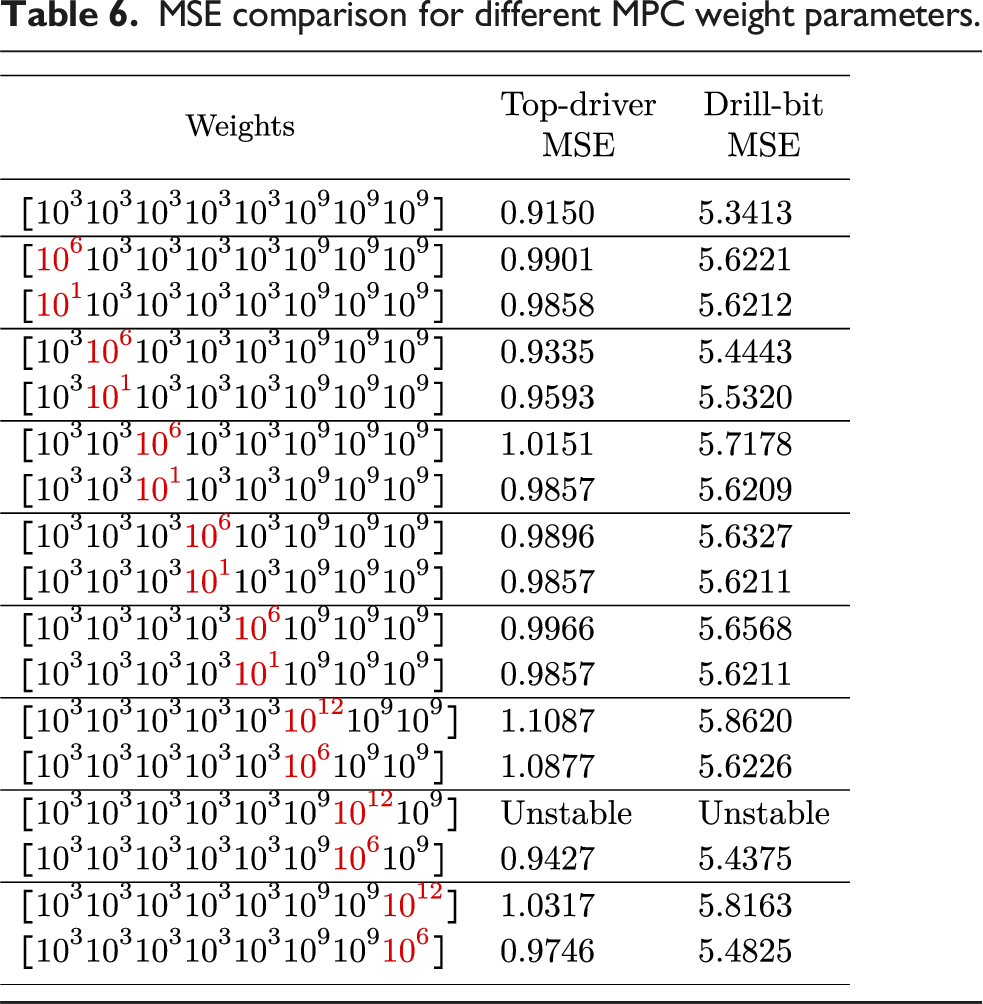
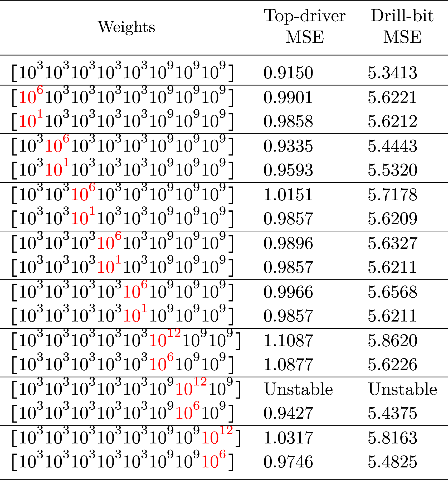
MSE comparison for different MPC weight parameters.
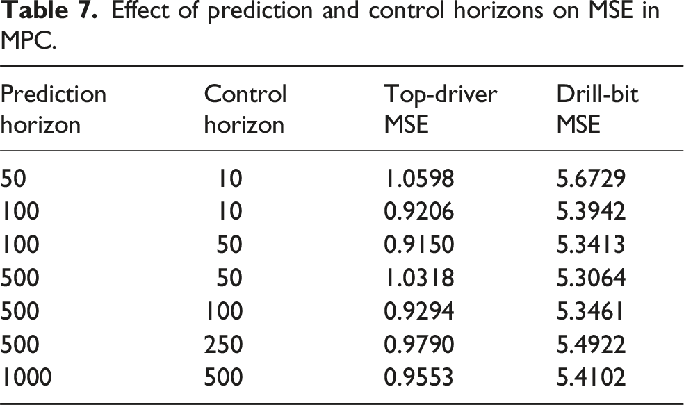
Effect of prediction and control horizons on MSE in MPC.
3.6. Wob uncertainty
Based on Figure 9, the control performance criteria in Tables 8 and 9 show that the proposed controller outperforms its counterpart in terms of MSE, rise time, and settling time. It is worth noting that, due to the presence of oscillations, the settling time cannot be precisely determined; therefore, the reported values correspond to the case without uncertainty. Regarding oscillations, although the Tube MPC produces larger oscillations at the top drive, it results in smaller oscillations at the drill bit. As shown in Figure 10, the SMC exhibits greater oscillations in the control inputs, whereas the PID controller produces a larger peak. Comparison of Tube MPC, SMC, PID, and LQT controllers with 5% uncertainty on W
ob
. (a) Comparison of top driver velocity performance of controllers with 5% uncertainty on W
ob
; (b) Comparison of the Bit angular velocity performance of controllers with 5% uncertainty on W
ob
. Comparison of top driver criteria with 5% W
ob
uncertainty. Comparison of drill bit criteria with 5% W
ob
uncertainty. Comparison of control inputs for Tube MPC, SMC, PID, and LQT controllers with 5% uncertainty for W
ob
.


3.7. LQT controller and tuning
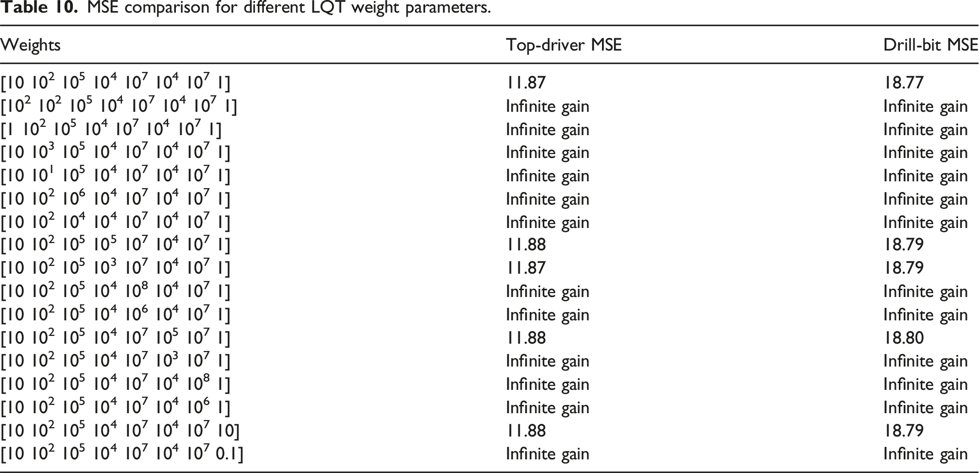
For the LQT controller, the augmented system shown in equation (21) was employed. The weight of the integrator was set to 109. Increasing this weight leads to unbounded controller gains, while decreasing it results in a significant increase in the MSE, reaching values of approximately 40.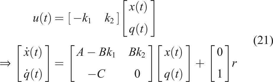



MSE comparison for different LQT weight parameters.
3.8. PID controller and tuning
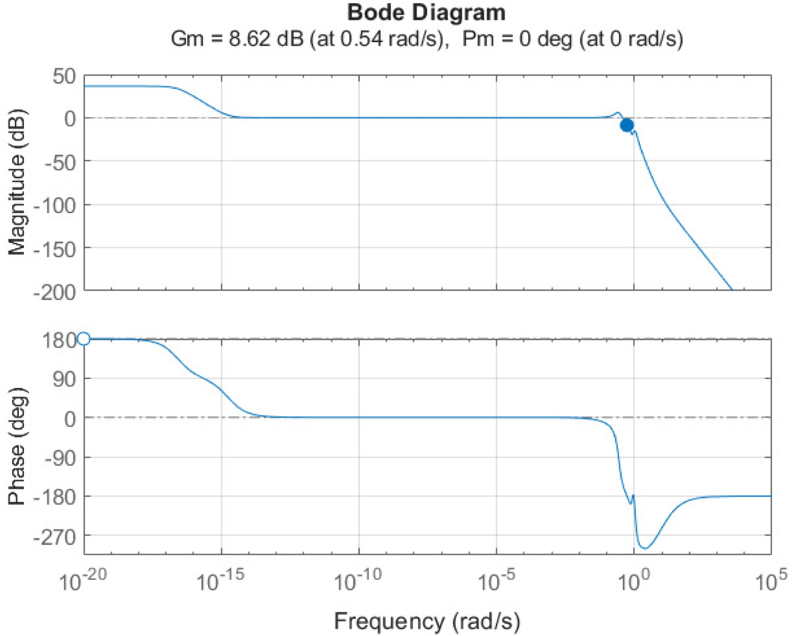
For the PID controller, the general form given in equation (23), which includes a high-pass filter on the derivative term as an implementation capability, has been considered. The corresponding coefficients are presented in equation (20). The Bode diagram of the closed-loop system is shown in Figure 11. Although the phase margin (PM) is relatively small, it’s because to get better rise time and faster performance, as illustrated in Figure 6. Further reduction of the PM could result in unstable system, which is undesirable for system performance. Bode diagram of the closed-loop system with gain and phase margins for stability analysis.
3.9. Unstructured time delays
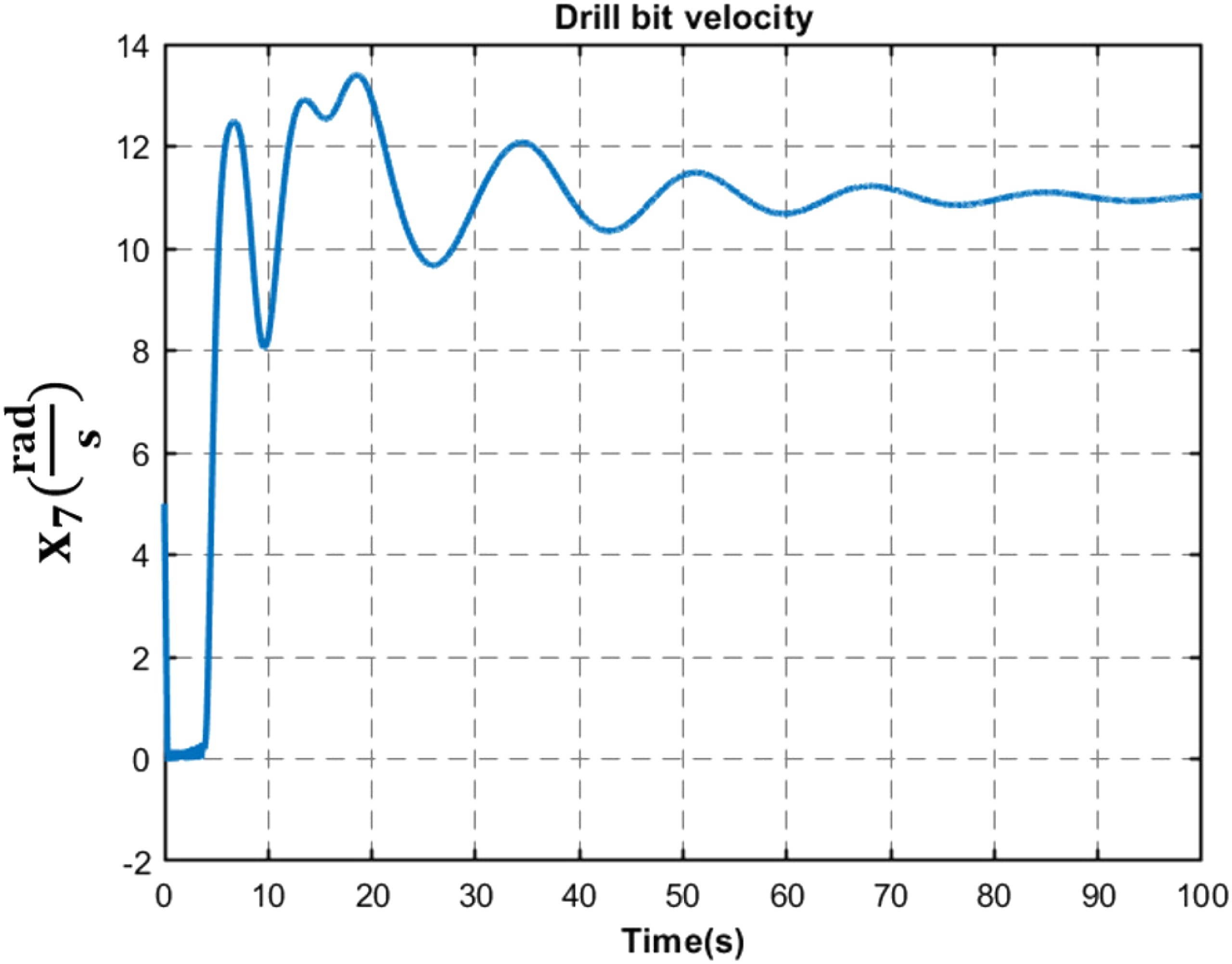
The Tube MPC controller exhibits inherent robustness against unstructured time delays. According to Shen et al. (2013), the worst-case delay in transmitting downhole data to the surface is approximately 5 ms. To demonstrate this robustness, Figure 12 presents the drill-bit velocity response when a 1-s delay is imposed on both drill collar and drill-bit measurements. Furthermore, Figure 13 illustrates the controller’s performance under multiple heterogeneous delays, where we assume 0.3 s for drill pipe data, 0.6 s for drill collar data, and 0.9 s for drill-bit data. These scenarios highlight the controller’s capability to maintain acceptable performance despite significant operational delays. Drill-bit velocity response under a fixed 1-s measurement delay. Drill-bit velocity response under heterogeneous variable delays.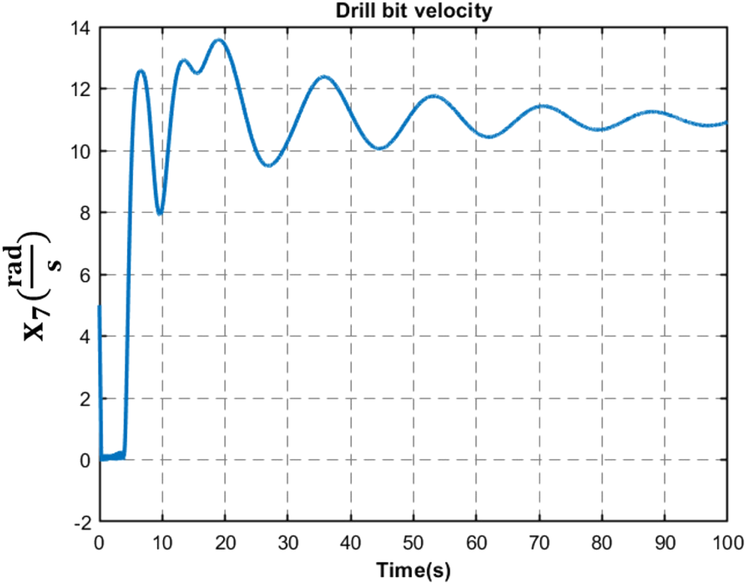
4. Conclusions
In this article, a four-degrees-of-freedom model is developed, and a robust tube MPC strategy is proposed to mitigate stick-slip oscillations in the drill string system. This approach effectively manages system uncertainties, such as variations in drill pipe inertia—impacted by pipe length—and changes in weight on the bit due to axial vibrations. Simulation results highlight the controller’s robustness, demonstrating its capacity to stabilize the system under these uncertain conditions. The proposed controller contributes to preventing stick-slip by actively limiting the rotary table torque, thereby avoiding the development of excessive differences in rotational speed or angular position along the drill string. By constraining these discrepancies, the controller effectively suppresses the onset of stick-slip dynamics. Compared to an SMC, the proposed controller achieves faster stabilization, reducing settling time by 41% at the top driver and 25% at the drill bit, with MSE reductions of 74% and 28%, respectively. The tube MPC also lowers control input peaks and reduces oscillations by 50% in the top driver and 35% in the drill bit under uncertainty. In comparison with a PID controller, the proposed controller achieves, in the top driver, a 69% improvement in MSE, a 40% reduction in settling time, and a 96% improvement in rise time; in the drill bit, it achieves a 50% lower MSE, a 42% faster settling time, and a 45% faster rise time. Furthermore, while the PID controller achieves 56% lower oscillations at the top driver, the tube MPC achieves 24% lower oscillations at the drill bit. Due to the very poor performance of the LQT controller, its results were not compared with those of the proposed method. Future research could focus on addressing periodic disturbances—commonly encountered in systems with rotating components such as motors—and on exploring explicit MPC approaches and validate the proposed control schemes through a co-simulation platform or laboratory implementation.
Footnotes

Funding
The authors received no financial support for the research, authorship, and/or publication of this article.
Declaration of conflicting interests
The authors declared no potential conflicts of interest with respect to the research, authorship, and/or publication of this article.