
Abstract
With the development of modern society, the advent of wearable exoskeleton devices has provided people with better experience and security in work and in life. However, since traditional rigid driving joints inherently lack impact cushioning capabilities, the impact force acts directly on the motors and human body, resulting in poor safety. Furthermore, especially for healthy wearers, since their motor function is intact and they are capable of independently engaging in various types of movements, the complexity and diversity of gait activities will also increase the uncertainty in control. To address the above issues, this paper proposes a compliant hip joint design for lower limb exoskeleton robots. This design employs a radial series elastic actuator (SEA) configuration, featuring an intuitive mechanical structure, convenient maintainability, and adjustable stiffness. Compared with traditional rigid driving joints, the SEA-based hip joint designed in this paper provides impact absorption and vibration cushioning capabilities, thereby enhancing the safety of human–robot interaction and improving control precision. Then an extended state observer-based sliding mode controller is designed to achieve precise trajectory tracking, where the extended state observer is used to mitigate external disturbances and modeling errors. The simulation results show that the proposed extended state observer-based sliding mode controller can achieve precise position control in the presence of vibrational and impact disturbances.
Keywords
1. Introduction
Lower limb exoskeletons constitute wearable mechatronic systems that synergistically integrate mechanical structures, biomimetic actuation, intelligent control architectures, and multimodal sensing modalities. These wearable devices have gained substantial research attention across diverse application domains, encompassing military augmentation, clinical therapeutics, and neurorehabilitation (Tan and Wang, 2013). The current technological landscape features several commercially deployed platforms, notably Raytheon’s tactical load-carriage system (Yuan et al., 2016), the XOS full-body powered exoskeleton (Murray et al., 2015), and medical rehabilitation exoskeletons including the ReWalk and HAL (Cha et al., 2014). These systems function through real-time acquisition of lower extremity kinematic parameters, enabling trajectory tracking and motion assistance for activities of daily living. Research indicates that exoskeleton robots can significantly reduce metabolic cost, cardiorespiratory burden, and musculoskeletal loading during ambulation, stooping, and load-bearing activities. Additionally, some advanced systems incorporating proactive balance control strategies can generate corrective joint moments in response to detected postural perturbations, thus enabling rapid dynamic stabilization and effective fall prevention.
To improve the level of human–robot interaction in exoskeleton robot systems and to cope with the dynamic changes and uncertainties in human–robot collaborative motion, the development of exoskeleton robot systems with compliant joint transmission systems is currently the mainstream approach. In addition to linear actuators and pneumatic muscles, series elastic actuators (SEAs) are another major implementation method for compliant joint transmission systems in exoskeleton robots.
In an SEA architecture, elastic elements are serially interposed between the power source and the load endpoint, thus giving the entire device a flexible output. Compared to traditional actuators, SEA-based driving joints have advantages such as high force controllability and accuracy, low output impedance, reversible drive, and shock resistance. Zhao et al. (2024b) proposed a four-parallel spring-based mechanism in the SEA. The experiments showed that the designed SEA could enhance the motion adaptation and landing buffer of the bioinspired robotic ankle. Carney et al. (2021) designed a moment-coupled cantilever-beam reaction-force SEA for untethered and powered bionic knee and ankle prostheses. The SEA was verified with the walking experiments on level ground and varied terrain. Dong et al. (2020) designed an SEA with a geared five-bar spring mechanism. The experiments showed that the SEA-based ankle-foot prosthesis could effectively imitate the function of human ankle and reduce energy consumption. Wang et al. (2024) proposed a novel variable transmission SEA, where an SEA-coupled variable transmission ratio adjusting mechanism was designed to meet torque-speed requirements in different exoskeleton-assisted locomotion modes. The feasibility of the proposed hip exoskeleton and the designed singular perturbation controller was verified by experiments. Liao et al. (2024) designed a flexible and portable back-support exoskeleton with a cable-driven SEA system. A torsion spring–support beam mechanism was designed in the SEA to prevent high cable force demand and resultant lumbar compression. Ding et al. (2024) designed a differential SEA, where precise force control was achieved with the deflection feedback of the SEA’s spring. The experiments showed that the SEA-based back-support exoskeleton could reduce the back muscles’ fatigue level during lifting. To reduce the mechanical impedance and acoustic noise, Qian et al. (2023) designed a nonlinear SEA which was coupled with a quasi-direct drive motor. Then a cascade proportional-integral (PI) controller was designed to assess the precision and robust of the designed SEA. Song et al. (2023) designed a crank-slider SEA for a knee exoskeleton. Then the precise force control of the designed exoskeleton was realized with an adaptive neuro-fuzzy sliding controller. Kang et al. (2023) designed an autonomous SEA-based hip exoskeleton and combined the SEA with a user interface to realize the efficient transfer of hip-joint torque during dynamic movement. Zhong et al. (2022) designed an SEA-based cable-driven lower limb exoskeleton. The experiments verified the efficacy of the prototype and gait-phase-based strategy in improving the symmetry of the temporal walking gait. Al-Dahiree et al. (2022) designed a compact, lightweight energy storage device with a rotary SEA. The experiments demonstrated that the designed lumbar support exoskeleton could effectively reduce wearers’ fatigue level while they were doing such tasks as carrying and lifting. Zhang et al. (2022) designed a two-motor variable speed transmission, which could adjust the torque-velocity relation in real time, for an SEA. The experiments showed that the SEA-based hip exoskeleton performed well in such task as sitting-to-standing, walking and climbing stairs. De Gaitani et al. (2022) designed a compact SEA based on a torsion spring for a rehabilitation lower limb exoskeleton. The experiments verified that the proposed SEA could effectively reduce the energy consumption and increase bandwidth. Aguirre-Ollinger and Yu (2021) designed a SEA, which could provide two stiffness levels according to the commanded force, for a rehabilitation lower limb exoskeleton. The experiments showed that the proposed switching force-tracking control strategy was effective for stroke survivors to correct their asymmetric gaits. In order to realize the optimal control of an SEA-driven exoskeleton, Li et al. (2021) proposed a generalized predictive control method. The experiments showed that the proposed method was almost model-free in comparison to the conventional model predictive control methods. Zhao et al. (2024a) proposed a backstepping control method integrating feedback linearization and extended state observer (ESO) for the hydraulic driven lower limb exoskeleton robot to achieve effective decoupling and high-precision trajectory tracking by transforming the coupled nonlinear system into canonical form and reconstructing states, with effectiveness validated through comparative experiments.
The inherent complexity of lower limb exoskeleton architectures, which is characterized by nonlinear dynamics and coupled input-output relationships, is further compounded by the integration of SEA-actuated joints, thereby substantially increasing the difficulty of modeling. Consequently, such hybrid systems exhibit heightened vulnerability to environmental perturbations and parametric uncertainties. Conventional proportional-integral-derivative (PID) methods exhibit inherent limitations, including suboptimal transient response characteristics and inadequate attenuation of system-induced oscillations. Consequently, such linear feedback strategies prove insufficient for high-precision trajectory tracking in lower limb exoskeleton systems (Zeng et al., 2020). Therefore, advanced control strategies must be adopted to ensure asymptotic stability in the presence of modeling errors and exogenous disturbances. Existing research have explored adaptive control (Kayacan et al., 2021), impedance control (Zhang et al., 2020), robust control (Salcido et al., 2023), computed torque control and so on. Although satisfactory outcomes have been attained with the above methods, these control methods suffer from inherent constraints. Specifically, computed torque control demands precise mathematical modeling, thereby compromising applicability in scenarios with significant unmodeled dynamics. Robust control requires that system uncertainties conform to describable bounded sets. Otherwise, the system will inevitably diverge or lose stability guarantees. Besides, Jin and Guo (2023) proposed an ESO-MPC integrated control strategy for lower limb rehabilitation exoskeletons subject to patient variability and system uncertainties, employing an extended state observer to estimate and compensate for lumped disturbances (including human interference, unmeasured states and nonlinearities) within a decoupled MPC framework, achieving significant trajectory tracking improvements (over 34% enhancement over conventional methods) validated through virtual experiments. Zhan et al. (2024) proposed a multilevel control strategy for lower limb exoskeletons that integrated LSTM-based intention recognition, variable admittance control, and fixed-time convergent control to achieve high-precision trajectory tracking and wearable comfort optimization across three training modes—passive, active, and passive-to-active—verified through both simulations and experiments. Kou et al. (2024) presented a multimodal human-exoskeleton cooperative control method integrating CPGs-based gait planning and admittance modulation to enable smooth switching among active, passive, and assist-as-needed modes, with an adaptive RBFNN backstepping controller ensuring tracking stability under model uncertainties, validated through experimental studies. Hasan and Alam (2025) presented the design of a 4-DOF lower limb exoskeleton with anatomically aligned joint axes, developed a subject-specific Lagrangian dynamics model, and proposed an adaptive sliding mode controller with boundary layer for chattering suppression and robust trajectory tracking, validated through simulations for neurorehabilitation applications.
In response to the pressing demand for robust performance under system uncertainties and external disturbances, sliding mode control has undergone extensive theoretical development and emerged as a dominant methodology in nonlinear system regulation. Extensive research in this area has produced significant advances. Esmaili and Haron (2015) proposed a saturation-based nonlinear switching function to eliminate chattering during the reaching phase and to ensure global robustness of the sliding mode control system. This method, however, merely guaranteed convergence to a boundary layer around the sliding surface rather than ensuring exact convergence to the sliding surface itself (Si et al., 2018). A fundamental limitation inherent to sliding mode control (SMC) architectures is the generation of control-induced chattering phenomena. To address this limitation, hybrid frameworks combining sliding mode control with nonlinear disturbance observers have been increasingly pursued, offering an effective compromise between robust performance and control smoothness (Baek et al., 2016). Chen et al. (2017) proposed a sliding mode feedback architecture enhanced by adaptive fuzzy-SMC synthesis to mitigate tracking errors. Nevertheless, the associated rule complexity introduced excessive parametric tuning requirements and significant computational cost. Zou et al. (2018) proposed a disturbance observer for manipulators and designed the controller using a sliding mode inversion approach. Although this method enabled satisfactory disturbance estimation and improved tracking performance, the design process was considerably complex. Rsetam et al. (2019) proposed a cascaded extended state observer (CESO)-based sliding-mode control method for underactuated flexible joint robots, which simplified the model via coordinate transformation and flatness approach, utilized CESO to attenuate noise and estimate disturbances for reducing chattering and switching gains, thereby achieving robust control for high-order systems validated through simulations and experiments. Zhao et al. (2021a) proposed a state observer for real-time external disturbance estimation, where chattering was mitigated via an adaptive sliding mode control mechanism. Zhao et al. (2021b) proposed a sliding mode control integrated with extended state observer (ESO) for an electrically actuated ankle exoskeleton, utilizing ESO to estimate and compensate for disturbances from modeling uncertainties and irregular human ankle motion, thereby reducing switching gains and chattering while ensuring robust high-precision torque tracking, with effectiveness validated through experimental studies. Rsetam et al. (2021) proposed a terminal sliding mode control method with cascaded finite-time sliding mode observer for flexible joint robots, which transformed the dynamics into canonical form to achieve finite-time estimation of states and lumped disturbances for noise attenuation and peaking reduction, ensured finite-time convergence and total robustness, and verified the effectiveness through real-time comparative experiments. Rsetam et al. (2024b) proposed a novel adaptive active disturbance rejection control strategy comprising an adaptive extended state observer and an adaptive state error feedback controller for uncertain nonlinear steer-by-wire systems with communication delays, achieving precise angular steering position tracking through dynamic lumped disturbance estimation and variable gain regulation, with its superiority demonstrated via comparative simulations against classical ADRC. Rsetam et al. (2024a) proposed a robust fast finite-time composite controller (FFTCC) based on a scaling finite-time extended state observer (SFTESO) for steer-by-wire systems with communication delays and disturbances, achieving rapid estimation of generalized disturbances and finite-time stabilization, with its superior tracking performance and robustness validated through multi-scenario comparative simulations. Centeno-Barreda et al. (2024) presented an adjustable lower limb exoskeleton with series elastic actuators (SEAs) and an extension mechanism for gait rehabilitation, proposing a nonsingular terminal sliding mode control with adaptive parameter adjustment to address trajectory tracking under uncertain dynamics and external disturbances, with effectiveness validated through simulations and experiments. Rsetam et al. (2025) proposed a generalized proportional-integral observer (GPIO)-based continuous sliding mode control (CSMC) strategy for uncertain SISO networked control systems with input/output time delays and matched/unmatched disturbances, employing Pade approximation for delay compensation and a novel disturbance-embedded sliding manifold to achieve robust output tracking, with effectiveness verified through simulations and experiments on Quanser’s servo module.
Numerous studies have integrated SEAs into exoskeletons’ driving joints to address the inherent lack of impact cushioning capabilities in traditional rigid actuation. However, rotary SEAs currently prevalent in exoskeleton applications predominantly employ elastic elements with irregular topological structures, suffering from manufacturing complexity, high cost, and non-adjustable stiffness. Motivated by these limitations, this paper proposes a SEA-based hip joint for lower limb exoskeleton robot to meet the need for safe and compliant human–robot interaction. Meanwhile, leveraging the inherent robustness of sliding mode control, an SMC-based controller is developed to mitigate dynamic modeling uncertainties and external disturbances. The main contributions of this research can be summarized as follows: • A radial SEA with symmetric tangential coil springs is designed for the hip joint of lower limb exoskeleton robots. With the advantages of intuitive mechanical structure, convenient maintainability and adjustable stiffness, the proposed SEA-based hip joint can achieve impact absorption, vibration cushioning, and enhanced human–robot interaction safety and control precision. • An extended state observer-based sliding mode controller, where dynamic modeling uncertainties and potential external disturbances are lumped into composite disturbance signals and fed back to the sliding mode controller, is employed to validate the dynamic modeling and structural design of the proposed SEA-based hip joint, particularly its impact absorption and vibration cushioning capabilities.
The remainder of this manuscript is organized as follows. Section 2 describes the mechanical design and dynamic modeling of the SEA-based hip joint. Section 3 develops the extended state observer design along with stability proof. Section 4 devises the extended state observer-based sliding mode controller, validates its stability, and presents simulation results with discussion. Section 5 concludes the paper.
2. Design of an SEA-based hip joint
2.1. Structural design and working principle
Traditional robotic driving joints primarily utilize a rigid design approach, where the driving joints consisting of motors and reducers. Due to the absence of elastic elements in this kind of design, the joint lacks compliance. When interacting with the environment, external impacts can cause joint damage. Therefore, flexible joints are incorporated into robotic arms to protect movement.
To ensure that the joint not only achieves precise motion control but also exhibits excellent compliance, this paper incorporates an SEA within the hip joint to provide flexibility. The key difference between our design and a traditional rigid hip joint lies in the inclusion of an elastic element within the SEA, which transmits power, resists impact, and provides torque feedback.
To ensure the suitability of the designed SEA for our lower limb exoskeleton prototype, the SEA must meet the following requirements: (1) The SEA should provide bidirectional transmission. (2) The SEA should be compact, lightweight, easy to install, and not interfere with the exoskeleton’s movement. (3) The SEA should be compatible with the selected MUA060S motor.
Currently, the elastic elements of SEAs can be primarily categorized into two types: combined and torsion springs. Combined springs primarily utilize linear springs for their elasticity. Their advantages include a simple design, easy control of torque transmission through the spring, and a strictly symmetrical structure, enabling multiple bidirectional torsional transmission. However, their disadvantage is their bulkiness. Torsion springs are typically monolithic, with relatively small radial and axial dimensions. They often utilize specialized elastomers, resulting in low overall mass. However, their asymmetric structure can easily lead to asymmetric response over time. Due to their complex design, their design and processing costs are relatively high compared to combined springs. The hip joint designed in this paper requires multiple bidirectional rotational transmission, and the forces acting on the lower limb are significant. Therefore, the SEA designed in this paper utilizes a combined SEA.
In this paper, the primary transmission method is spring compression, so the stiffness of the entire SEA module depends on the stiffness of the spring. Given that the three selected springs are identical and evenly distributed in the SEA module, each spring is subjected to the same force. As shown in Figure 1, the concept is to apply the motor input torque to a sweeping arm, which in turn compresses a spring. When the sweeper moves at a small angle, the spring can be approximated as a linear motion, so the torque can be transmitted regardless of the forward or reverse rotation of the motor. The working principle diagram of the SEA.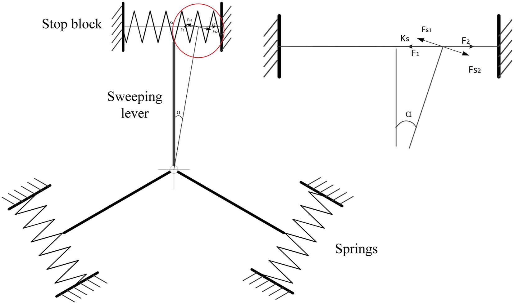
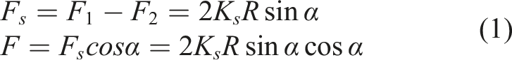
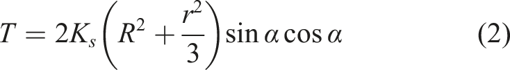
From the SEA structural design diagram, we can see that the relationship between the torque output F
s
of the entire SEA and the torque F exerted by the spring element on the barrier arm is as follows:
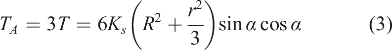
As shown in Figure 1, the SEA contains three groups of springs, corresponding to three groups of sweep arms. Equation (2) represents the torque generated by one group of springs on the sweep arm. Therefore, the torque T
A
generated by all the spring groups in the entire SEA can be expressed as equation (3).
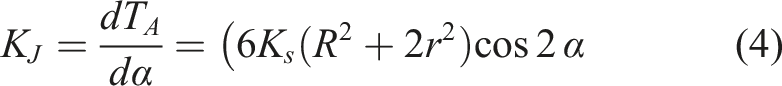
Since the spring stiffness is known, the relationship between the SEA’s transmission stiffness K
J
and the spring stiffness K
s
can be derived from equation (4) to calculate the SEA transmission stiffness. This article assumes that all structural flexibility originates from the flexible joint component itself, ignoring rod deformation and other driving stiffness. Therefore, equation (4) can be used to express the stiffness relationship between the flexible joint as a whole and the spring assembly.
The 3D model and assembly drawing of the SEA-based hip joint is shown in Figure 2. Figure 2(b) shows the following components from left to right: 1–Motor, 2–Spring front shell, 3–Spring rotation stop, 4–Wire spring, 5–Rotation shaft, 6–Spring fixing rear shell, 7–Connecting plate, 8–Leg connector. The central shaft serves as the input through the center hole and is connected via rolling bearings. In the model, the central shaft is connected to the motor, and the stopper is fixed to the disc. The motor torque is transmitted to the central shaft, and the buffered torque is transmitted to the motor housing via a compression spring. The thickened housing is connected to the load, driving the load to rotate, thus achieving power input and flexible output. Since the designed SEA needs to be used in a lower limb exoskeleton robot, it needs to be as lightweight as possible. To reduce the overall weight of the SEA, all components except the wire spring are made of lightweight aluminum alloy, while the wire spring is made of structural steel with higher density and rigidity. 3D model and assembly drawing of the SEA-based hip joint.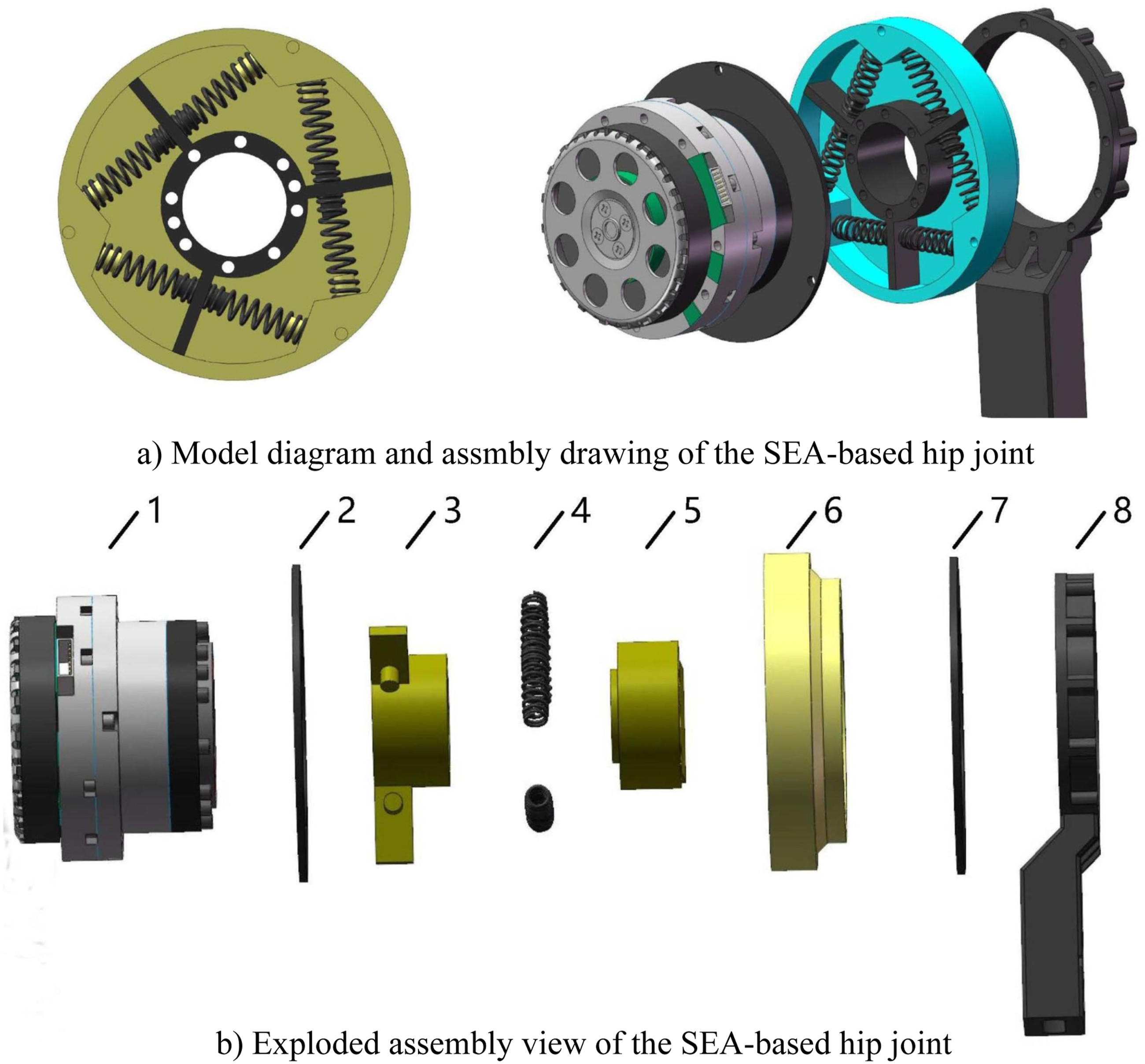
According to the working principle of a rotary SEA, when the servo motor receives the control command, it will transmit the output torque to the outer ring of the elastic element and then transmit the torque from the inner ring of the elastic element to the transmission shaft through the deformation of the elastic element. Finally, the torque is transmitted to the output load through the transmission shaft to realize the torque transmission of the SEA. The Hall sensor of the servo motor is used to obtain the angle value of the motor, that is, the angle value of the outer ring of the elastic element. The absolute encoder is used to obtain the angle value of the transmission shaft, that is, the angle value of the inner ring of the elastic element. The angular displacement between the outer and inner rings corresponds to the elastic deformation of the flexible element, which can be measured and converted to determine the SEA’s output torque.
Research indicates that the peak hip joint torque for healthy human is approximately 56 Nm. This paper uses ANSYS to analyze the deformation of the SEA’s linear spring when the maximum torque is 56 Nm to verify the design’s rationality. As depicted in Figure 3, the linear spring undergoes maximum deformation at full compression without causing any structural interference. Thus, the SEA’s structural design shown in Figure 2 can fully satisfy the operational demands of hip joints in lower limb exoskeleton systems. The maximum deformation diagram for the SEA’s spring.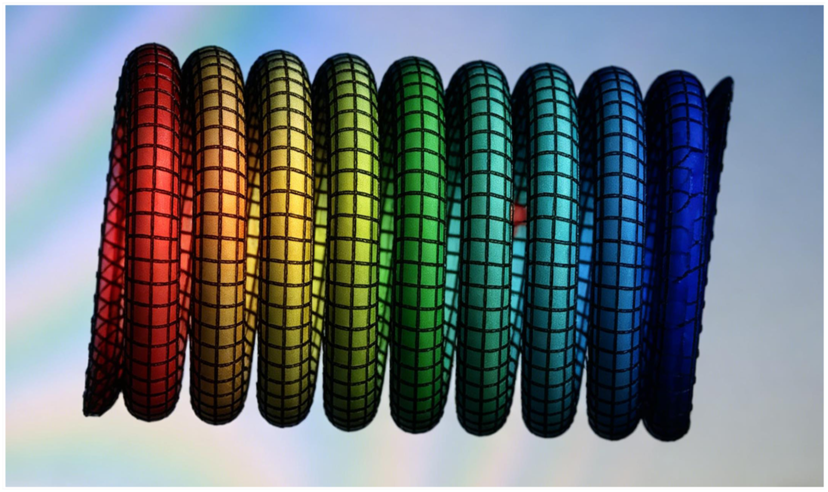
2.2. Dynamic modeling of the SEA-based hip joint
• Assumption 1: The motor shaft is coaxial with the flexible joint shaft. Role: Ensures the simplified dynamic model captures the primary motion transmission without misalignment effects. • Assumption 2: The flexibility of the flexible joint comes solely from the wire spring. Role: Allows the stiffness characteristics to be determined by the spring properties alone, ignoring structural deformations of other components. • Assumption 3: The servo motor is considered as an ideal torque input source. Role: Simplifies the motor dynamics to focus on the SEA-load interaction, excluding motor electrical dynamics and friction nonlinearities. • Assumption 4: The load end of the SEA is fixed when analyzing the system stability and deriving the transfer function. Role: Enables the derivation of the system transfer function of the SEA-driven joint for stability analysis.
Figure 4 presents the force-deformation characteristics of the linear spring versus SEA rotation angle derived from ANSYS analysis. By performing linear fitting on the stiffness characteristics curve in Figure 4, the torque output model of the single-wire spring is y = 5x. The stiffness characteristic curve of the rotary SEA.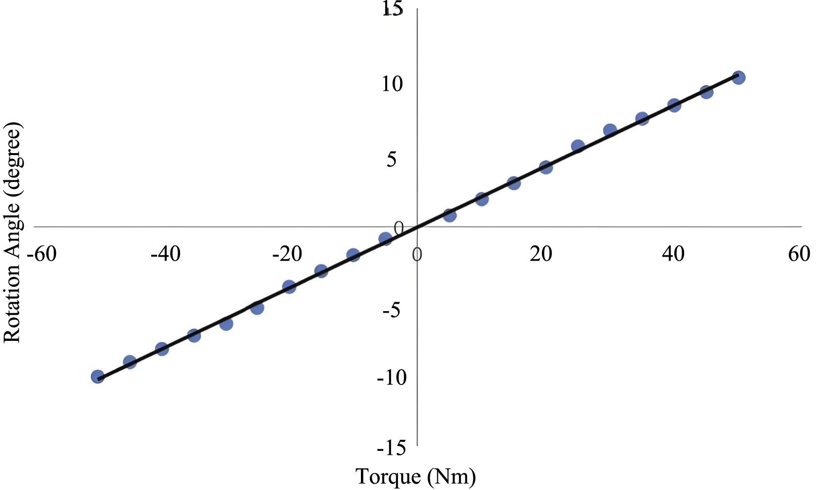
Since the performance and control effect of the SEA drive joint are mainly related to the dynamic model of the SEA and the load end, the motor and reducer are integrated into a module (i.e., the motor module) to facilitate dynamic modeling.
Figure 5 presents the simplified model of the rotary SEA. τm is the driving force/torque of the electric motor, K is the stiffness coefficient of the spring, qm is motor rotation angle position, qh is load location, and τh is the output torque for SEA. When a driving voltage is applied to the motor, the driving force generated by the motor τm acts on the drive system Jm, producing acceleration and causing the motor to rotate. The output torque is then transmitted through the spring to drive the load. The model of the SEA-based hip joint.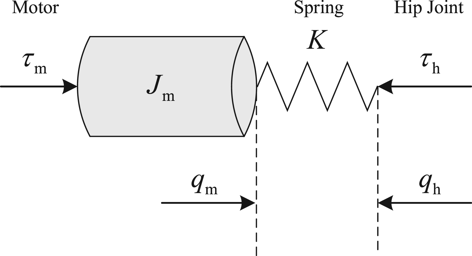
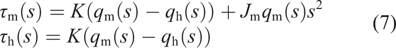
From Figure 5, we can see that:

According to Hooke’s Law:

From the Laplace transform of equations (5) and (6), we can obtain:
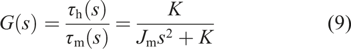
From equations (6) and (7), we can obtain:
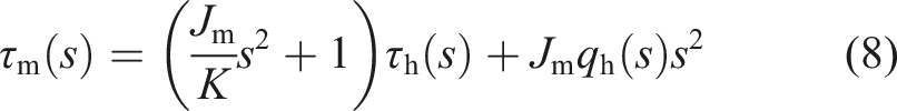
To analyze the system stability of the SEA-driven joint, according to the assumption that the load end of the SEA is fixed in Esmaili and Haron (2015), the system transfer function of the SEA-driven joint is defined as:
The Bode diagram corresponding to a spring stiffness coefficient of 5 N/mm, measured using MATLAB, is shown in Figure 6. The curve finally coincides with −180°, indicating that the designed SEA drive joint is in a critical stable state of the system. The Bode diagram of spring stiffness.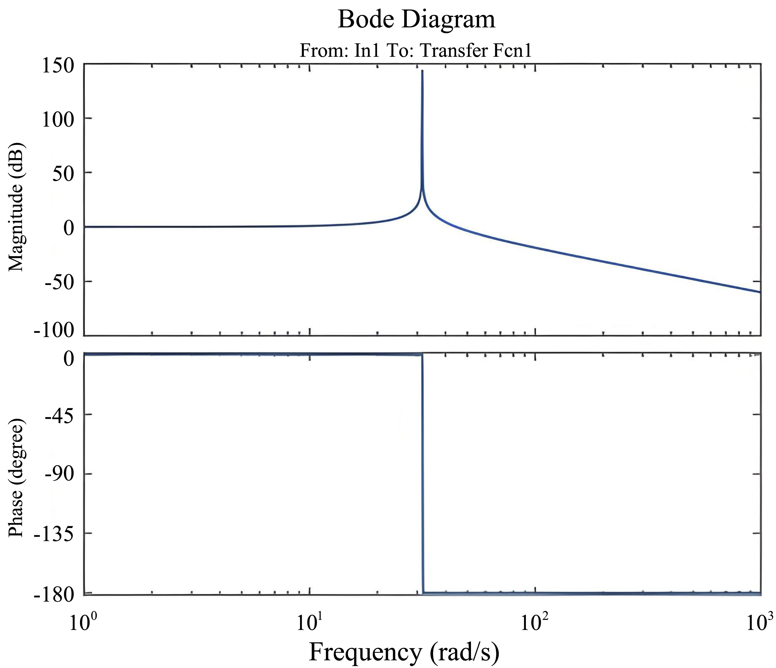
3. Design and stability proof of the extended state observer
3.1. Design of the extended state observer
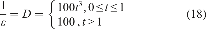
• Assumption 1: The lumped disturbance λ(t) and its derivative are bounded, that is, |λ(t)| ≤ D and Role: Guarantees the convergence of the extended state observer estimation error and ensures the stability of the observer dynamics. • Assumption 2: The coefficients α1, α2, α3 are chosen such that the polynomial s3 + α1s2 + α2s + α3 satisfies the Hurwitz condition. Role: Ensures the stability of the observer error dynamics and enables the convergence of state estimation. • Assumption 3: The observer gain parameter ɛ is sufficiently small to achieve fast convergence, while the time-varying design 1/ɛ = D mitigates the peaking phenomenon. Role: Balances the trade-off between convergence speed and transient performance in the high-gain observer.
For ease of design, the designed SEA drive joint is considered as a second-order system with external disturbances.
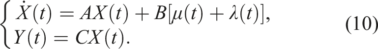
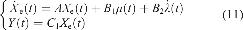
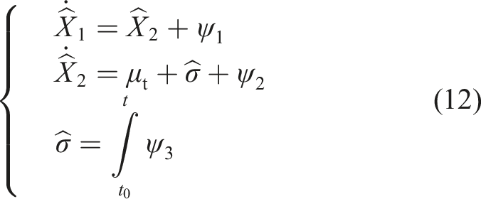
Treating perturbation λ(t) as an extended state, we can obtain the following extended system:
Define:
Utilizing the system representation in equation (11), the extended state observer is constructed as follows (Han (2009)):
3.2. Stability proof of the extended state observer
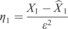
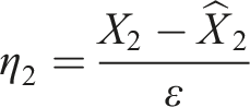
Define:
Set
Because:

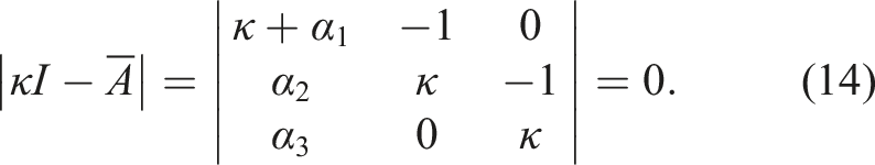
The characteristic equation of the matrix is:
Then

P is a positive definite matrix, and satisfies that for any given positive definite symmetric matrix Q, there exists
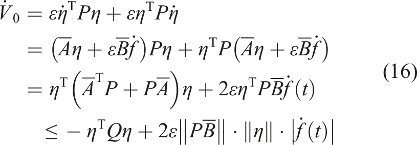
From
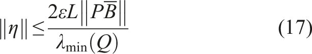
The convergence condition reveals that the observation error η converges at a rate governed by parameter ɛ. According to singular perturbation theory, smaller value of ɛ yields faster convergence. The observation error asymptotically approaching zero as ɛ → 0.
However, the extended state observer operates as a high-gain system. Thus, a significant mismatch between the observer and system initial conditions induces peaking phenomena for sufficiently small ɛ, which will degrade transient performance. To mitigate this effect, ɛ is designed as follows:
The designed extended state observer was simulated and verified using MATLAB. Assuming the uncertain disturbance follows a sinusoidal profile, Figure 7 demonstrates the disturbance estimation performance of the proposed extended state observer. Disturbance tracking of the extended state observer.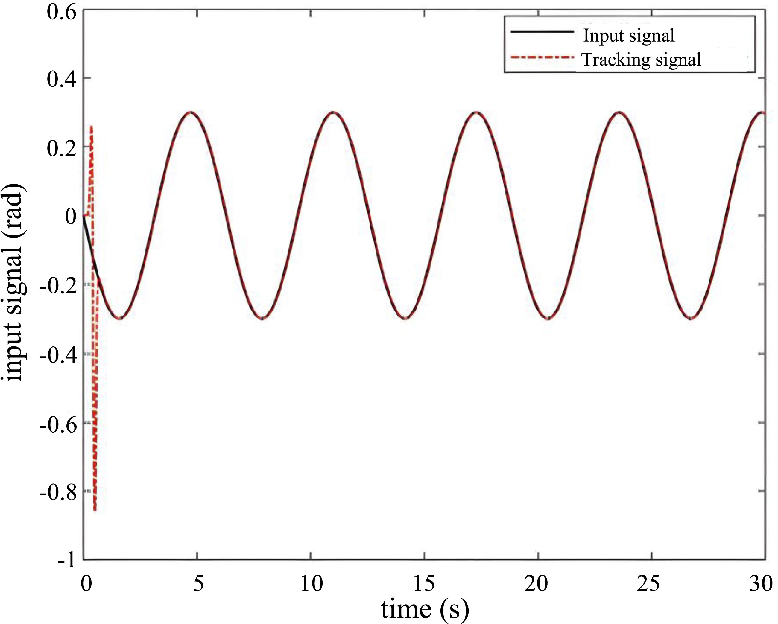
The tracking result in Figure 7 demonstrates that the proposed extended state observer can effectively track uncertain disturbances with favorable dynamic performance. Utilizing this capability, an observer-based sliding mode controller is subsequently developed to feed back the uncertain errors in the modeling of the SEA-driven system to the sliding mode controller for control, thereby achieving accurate position tracking of the hip joint compliant transmission system.
4. ESO-based sliding mode control
4.1. Design of the ESO-based sliding mode controller
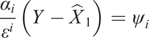
• Assumption 1: The system states are measurable or observable, and the output Y(t) is available for feedback control. Role: Ensures the feasibility of the proposed observer-based controller using estimated states. • Assumption 2: The control gain kg > 1/2 to guarantee the negative definiteness of the Lyapunov function derivative. Role: Ensures the asymptotic stability of the sliding mode control system and the convergence of the sliding surface. • Assumption 3: The estimated disturbance Role: Validates the separation principle between the observer and controller design, ensuring the closed-loop stability under composite disturbances. • Assumption 4: The desired trajectory Role: Guarantees the boundedness of the tracking error dynamics and the feasibility of the feedforward compensation term in the control law.
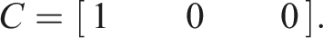
Figure 8 presents the control architecture of the observer-based sliding mode controller, where τm is the motor torque, τh is the control output torque, θm is the control input angle, and θh is the output angle. The control block diagram of the ESO-based sliding mode controller.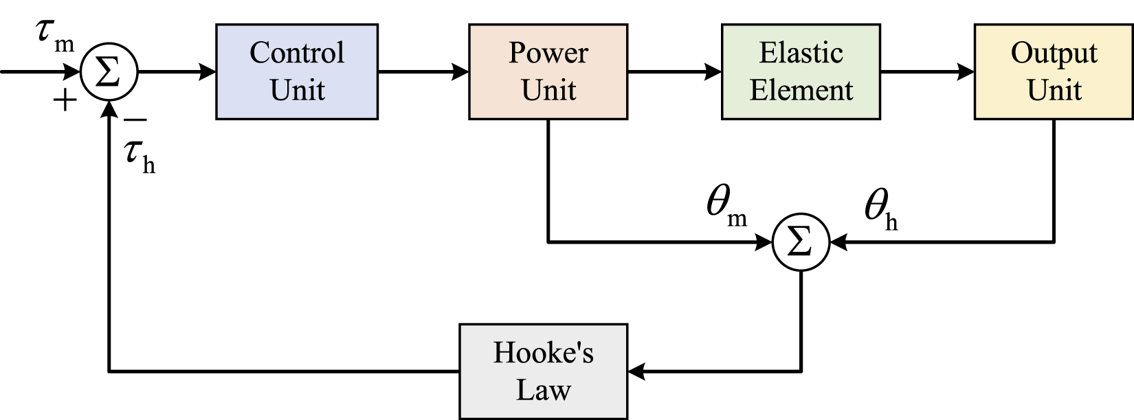
Define the system’s error variable as:

For the controlled object model:

The switching function is designed as follows:

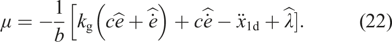
Design the ESO-based sliding mode controller as follows:
4.2. Stability proof of the ESO-based sliding mode controller
The Lyapunov function for the sliding mode control is defined as:
Then
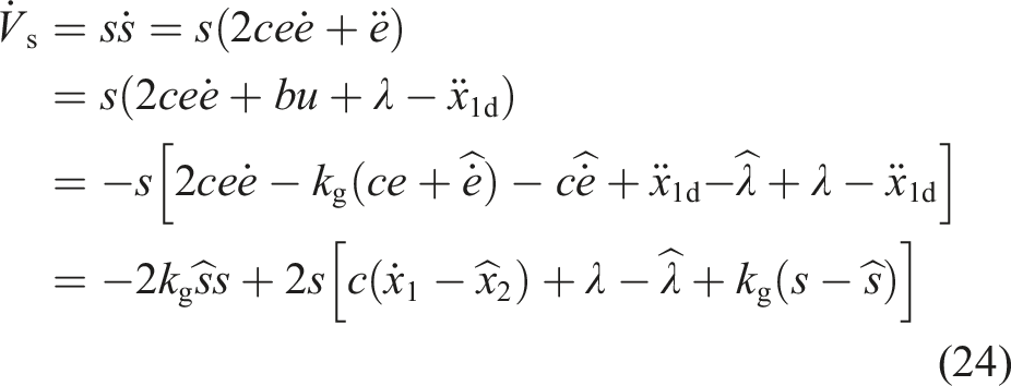
Define

Then

Since Γ depends on the observation errors of each state of the extended state observer, let Δmax ≥Γ, then:
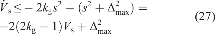
For
Define α = 2kg − 1,
Take kg >
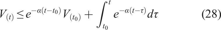
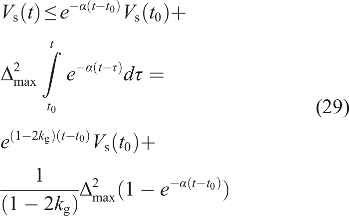
Given that V
s
(t) ≥ 0, the convergence rate is governed by the control gain and observer parameter ϵ. For sufficiently large gains and sufficiently small ϵ,
4.3. Results and analysis
The proposed ESO-based sliding mode control strategy is performed on a laptop with an Intel Core i7-8750H processor (6 cores, 2.2-4.1 GHz), 32 GB DDR4 RAM, and an NVIDIA GeForce GTX 1080 graphics card (8 GB GDDR5X). The system ran MATLAB R2016a/Simulink (MathWorks, USA) under Windows 10 Pro 64-bit operating system. To emulate the periodic motion of the hip joint in a lower limb exoskeleton, a sinusoidal trajectory is commanded as the reference input. The position tracking performance of the ESO-based sliding mode controller is illustrated in Figure 9. Position tracking of the ESO-based sliding mode controller.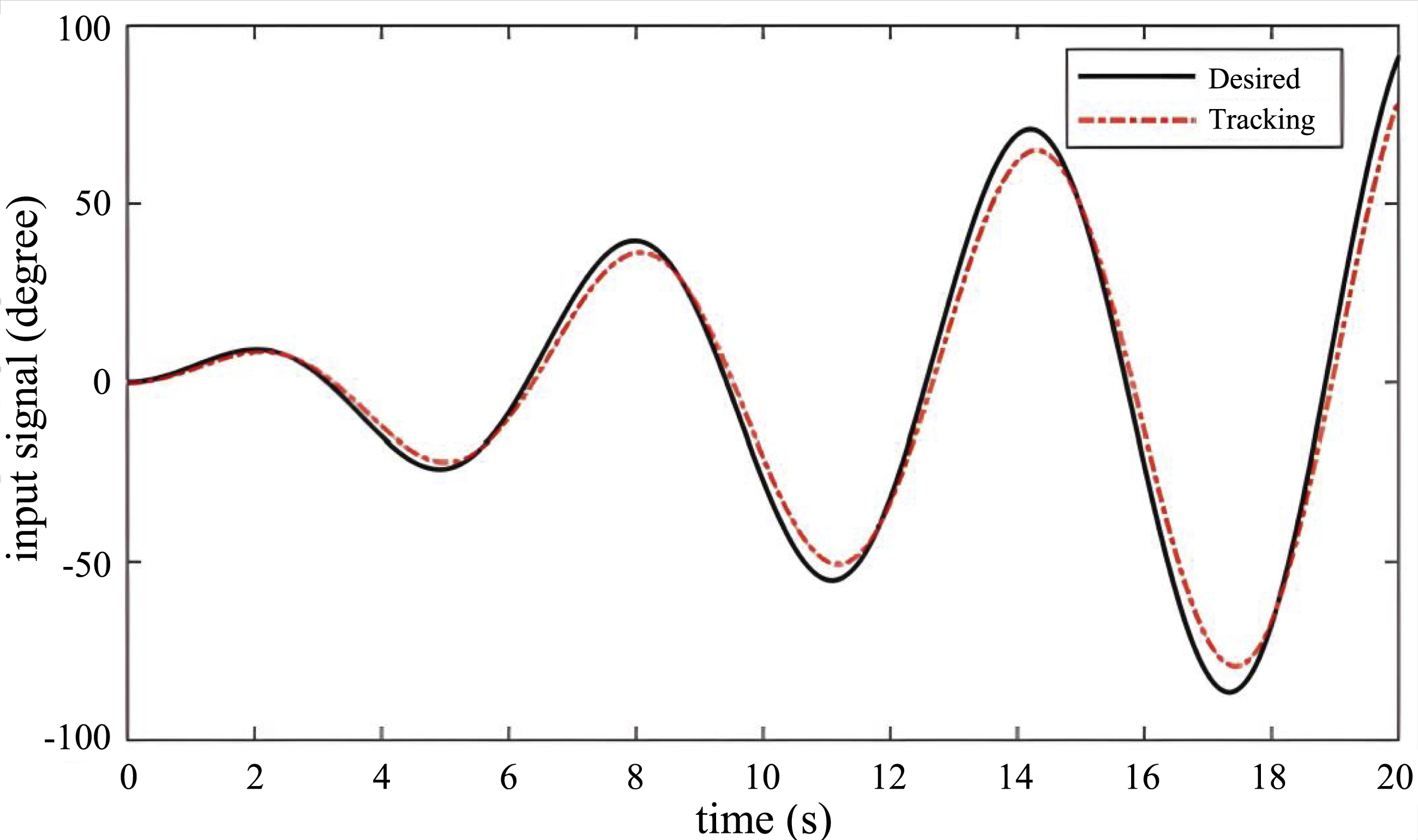
Human–robot collaborative locomotion will introduce vibrations and unmodeled disturbances. To assess controller robustness under realistic operating conditions, stochastic noise and peak signals are added to the reference trajectory to simulate the vibrations and external impacts. The corresponding position tracking performance under vibrational and impact disturbances is illustrated in Figures 10 and 11, respectively. Position tracking in the presence of vibration. Position tracking in the presence of external impact.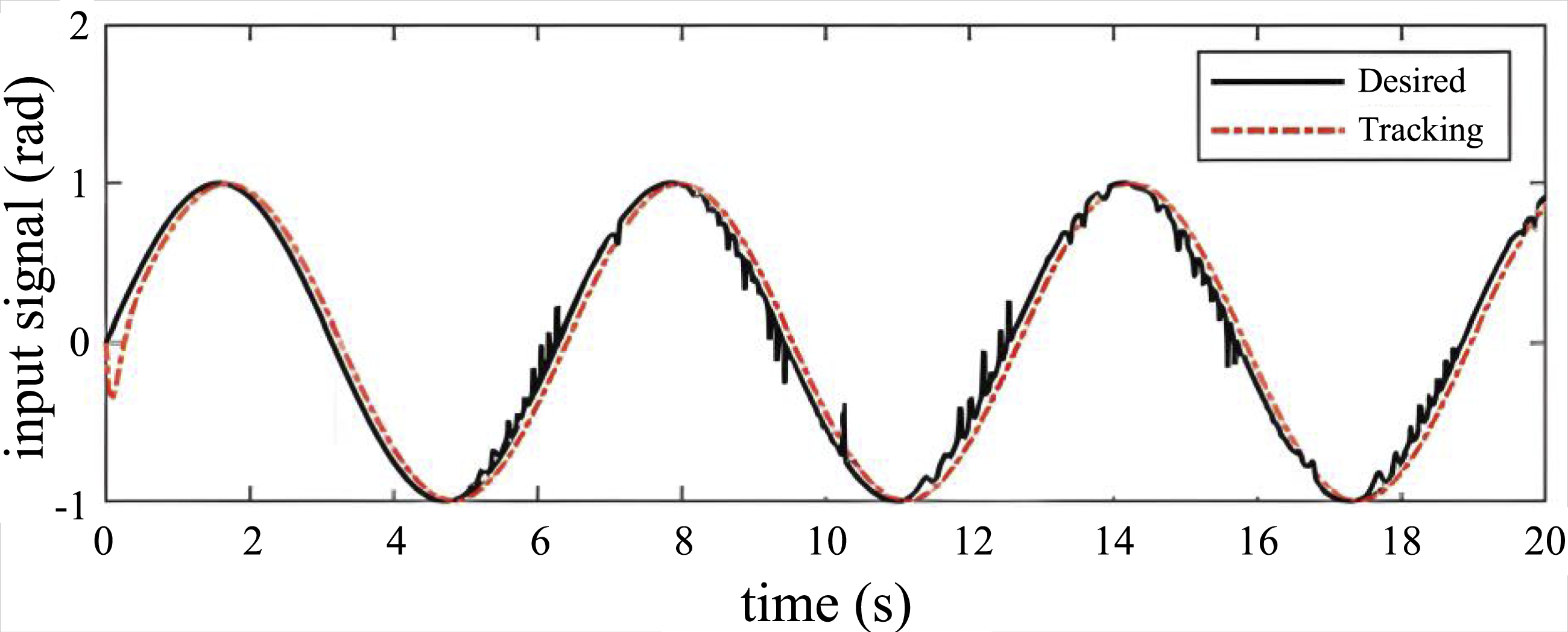
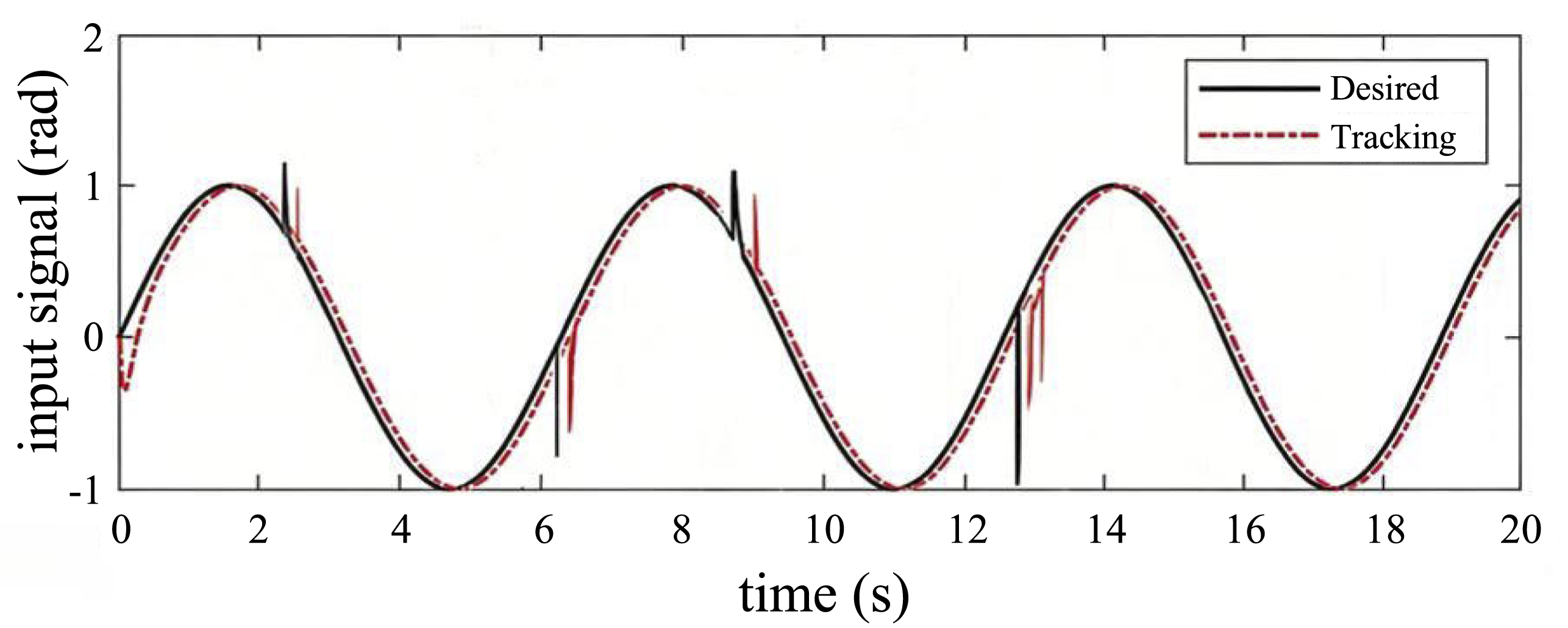
As shown in Figures 9–11, the extended state observer-based sliding mode controller exhibits excellent tracking performance and robustness under three typical reference signals. As illustrated in Figure 9, under disturbance-free conditions, the actual tracking trajectory (red dashed line) is highly consistent with the desired trajectory (black solid line). The controller achieves a minimal steady-state tracking error (peak error <0.1 rad), with negligible phase lag and high amplitude tracking accuracy. In terms of anti-disturbance performance, the vibration disturbance test in Figure 10 further verifies the robustness of the controller. Under continuous high-frequency vibrational noise interference, the tracking signal exhibits slight fluctuations but still closely follows the desired trajectory as a whole, with the steady-state tracking error maintained within a small range. The impact disturbance test in Figure 11 demonstrates that when the system is subjected to external impacts at 2.5 s, 6.5 s, and 12.5 s, the maximum tracking deviation is approximately 0.2–0.3 rad, and the system can quickly recover to the desired trajectory within 0.5–1s, reflecting favorable transient disturbance rejection capability. The analysis of Figures 9–11 demonstrates that the proposed control strategy maintains satisfactory tracking accuracy despite persistent vibrational disturbances. When there is a large external impact, the controller can quickly respond to external disturbances and continue to achieve accurate position tracking.
5. Conclusion
To enable user-friendly human–robot interaction and cooperative locomotion, this paper presents the design and control of an SEA-based hip joint in lower limb exoskeletons. The structural validity of the proposed SEA is verified through stress-strain analysis. Subsequently, the dynamic model is established by fitting the SEA stiffness characteristics. Based on this model, an ESO-based sliding mode controller is designed with proven stability guarantees. Simulation results demonstrate that the proposed control strategy is capable of achieving precise position control in the presence of modeling errors and uncertain disturbances.
This work can be applied not only to other compliant joints of exoskeleton robots (such as the knee joints and ankle joints) but also to a broader range of human–robot interaction systems. However, the research still has several limitations that need to be addressed. First, this work mainly focuses on the mechanical design of the SEA-based hip joint, while the design of the extended state observer and sliding mode control has not been optimized in combination with the structural characteristics of the proposed SEA mechanism. Second, the robustness analysis under extreme disturbances and the evaluation of control energy consumption remain to be further investigated. In future research, we will address the aforementioned limitations by optimizing both the mechanical structure of the SEA and the control algorithm parameters. Moreover, we will conduct multi-scenario human–robot collaborative experiments to systematically explore key issues such as computational complexity, real-time implementation feasibility, control energy consumption, performance boundaries, as well as wearing comfort and assistance effectiveness evaluation.
Footnotes
Funding
The authors disclosed receipt of the following financial support for the research, authorship, and/or publication of this article: This work is funded by the Tianjin Science and Technology Planning Project under Grant 21YFFCYS00130.
Declaration of conflicting interests
The authors declare no potential conflicts of interest with respect to the research, authorship and publication of this article.