






Abstract
This study investigates the free vibration behavior of cylindrical panels and shells of revolution integrated with piezoelectric patches. Based on the first-order shear deformation theory and Hamilton’s principle, the mechanical equations of the shell and panel are formulated. The governing electromechanical equations are derived using the constitutive relations of piezoelectric materials and Maxwell’s equations. To model the host system with piezoelectric material as both a complete shell and a panel, and to represent the piezoelectric material as a patch, the two-dimensional Generalized Differential Quadrature (2D–GDQ) method is employed. Utilizing of the 2D–GDQ approach is essential for accurately capturing variations in both the axial and circumferential directions, which cannot be achieved with a one-dimensional formulation. The natural frequencies of the shell and panel with piezoelectric patches are computed under various electrical and mechanical boundary conditions. The accuracy of proposed model and numerical approach is validated through comparisons with published results and finite element simulations conducted in Abaqus software. Furthermore, the study examines the influence of key geometric parameters—including the radius and length of the host panel, as well as the thicknesses of the piezoelectric patch and the host shell—on the natural frequencies.
Keywords
1. Introduction
Shells of revolution, such as cylindrical, conical, and spherical shells, are extensively used in various engineering applications, including aerospace, mechanical, and civil industries. Due to their high strength-to-weight ratio, these structures are highly regarded for their ability to sustain significant loads while maintaining a low weight. Among these, cylindrical shells are particularly favored in industrial applications owing to their unique geometric characteristics. In recent decades, the integration of piezoelectric materials has gained considerable traction, especially in fields like energy harvesting and active vibration control. The combination of piezoelectric materials with structural elements such as shells offers promising opportunities to develop multifunctional systems capable of both structural performance and energy conversion.
The equations of motion of cylindrical shells have been derived based on various shell theories, each characterized by distinct assumptions. The foundational contributions to shell theory trace back to the works of Love (1888) and Flügge (2013). Over time, numerous variants of shell theories have been proposed, some simplifying Flügge’s original equations by neglecting certain terms. Extensive research has been conducted over the years to refine these models and enhance their applicability (Sanders, 1960; Holmes, 1989; Carrera, 1991, 1999; Bhimaraddi, 1984). Furthermore, various solution methods have been developed to solve the governing equations of shells, ranging from energy-based approaches such as the Galerkin and Rayleigh-Ritz methods (Li et al., 2022; Pang et al., 2023; Zhou et al., 2024; Weiwei et al., 2024; Xu et al., 2025), to exact analytical solutions explored in studies of Li et al. (2018); Forsberg (1969); Khalifa (2011); Goldman (1974).
In recent years, the increasing global demand for sustainable and renewable energy sources has propelled research efforts in energy harvesting technologies. Among the various techniques, piezoelectric energy harvesting has emerged as a highly effective solution due to its direct conversion of ambient mechanical vibrations into usable electrical energy. This feature is particularly valuable in environments where traditional power sources are impractical or where long-term, maintenance-free operation is desired. Structural components such as beams, plates, and shells frequently encounter dynamic loads and environmental vibrations in diverse engineering applications, including aerospace structures, bridges, and mechanical systems. By embedding piezoelectric materials into these structural elements, it becomes feasible to capture mechanical vibrations and transform them into electrical power, thereby transforming passive structures into active energy-harvesting devices. Numerous studies have investigated the implementation of piezoelectric materials on beams, plates, and shells to optimize energy extraction efficiency. These studies typically focus on developing coupled electromechanical models to accurately describe the interaction between mechanical deformation and piezoelectric response. Optimization of factors such as material properties, boundary conditions, and excitation frequencies plays a crucial role in enhancing energy harvesting performance.
In 1997, for the first time, Umeda et al. (1997) explored the fundamental concepts of a generator that converted mechanical energy into electrical energy using a piezoelectric vibrator and a steel ball. They examined the effects of various piezoelectric vibrator characteristics and proposed an equivalent electrical circuit to simulate the power generation mechanism. Their findings revealed that maximum frequencies corresponded to the resonant vibration modes, and the calculated output voltage waveforms closely matched experimental measurements. The study concluded that increasing the electromechanical coupling coefficient and reducing the dielectric constant led to improved efficiency. Smits and Choi (1991) derived the fundamental equations for a unimorph piezoelectric actuator mounted on a cantilever beam. They analyzed the electromechanical behavior of the beam under various boundary conditions, considering both applied moment at the free end and distributed force along the beam. In a subsequent study Smits et al. (1991) extended their work to a beam with two bonded piezoelectric layers under similar boundary and loading conditions. Qing et al. (2006) introduced a semi-analytical method for static and dynamic analysis of a plate with multiple piezoelectric patches. Their model incorporated shear stresses and inertial moments within the plate equations. In the realm of advanced composite plates, research has been conducted to investigate the free vibration and vibro-acoustic responses of two types of piezoelectric functionally graded carbon nanotube-reinforced composite (FG-CNTRC) plates. The dynamic equations were derived using third-order shear deformation theory and Hamilton’s principle. Employing Navier’s method, the vibration frequencies and structural-acoustic responses of simply supported plates under concentrated harmonic excitation were obtained, with theoretical results validated against finite element simulations. The study compared the two configurations and discussed the influence of parameter variations on the dynamic and acoustic behavior (Li et al., 2025). Furthermore, the free vibration and dynamic response of bidirectional functionally graded (2D-FGM) plates integrated with piezoelectric layers and subjected to a moving mass have been analyzed. A finite element model based on a four-variable refined plate theory (HSDT4) was developed, and the Newmark method was employed to compute transient responses. The effects of parameters such as moving mass velocity and weight, along with electrical and mechanical boundary conditions, were comprehensively examined (Tran et al., 2023). In a complementary methodological approach, a Spectral-Tchebychev (S-T) dynamic model was proposed to analyze the free and random vibration characteristics of plates with bonded piezoelectric patches under random excitation. Utilizing a multi-partition strategy and first-order shear deformation theory (FSDT), the governing equations were derived for sub-plates, with boundary and coupling conditions handled via an artificial spring technique. Random excitation was introduced using the pseudo-excitation method (PEM). The model’s accuracy was verified against finite element results and existing data, and the influence of key parameters—such as patch position, size, and type—on the vibrational response was systematically investigated Gao et al. (2023).
Sheng and Wang (2009), employing the first-order shear deformation theory (FSDT) and Maxwell’s equations, formulated the electromechanical equations for a cylindrical shell subjected to external moving excitations. They utilized a hybrid approach combining modal analysis and integral methods to accurately capture the relationship between displacement and electric potential. Alibeigloo and Kani (2010) applied three-dimensional elasticity theory and combined the differential quadrature method (DQM) with state-space techniques to study the free vibrations of a multilayered cylindrical shell with a piezoelectric layer. They developed a general solution using Fourier series expansions for simply supported boundary conditions, validated their results against established references, and examined the influence of various parameters such as boundary conditions, radius-to-thickness ratio, length-to-radius ratio, and piezoelectric layer thickness on the natural frequencies. Another work provided a rigorous three-dimensional elasticity solution for the static and free vibration behavior of functionally graded carbon nanotube-reinforced cylindrical panels embedded in piezoelectric layers, focusing on the influence of the material gradient index and CNT distribution (Asadinia et al., 2025). Further, Bodaghi and Shakeri (2012) investigated the free and excited vibration of a simply supported functionally graded material (FGM) cylindrical panel covered with a piezoelectric layer. They subjected the panel to time-dependent impact forces and derived the dynamic response using FSDT and Maxwell’s equations. This study also considered open-circuit and short-circuit electrical boundary conditions and examined their influence on system behavior, employing Fourier series and Laplace transform techniques for the solution. Sayyaadi and Farsangi (2014) derived the dynamic equations of a thick doubly curved shell with a piezoelectric layer using third-order shear deformation theory. By applying simply supported boundary conditions and eliminating spatial derivatives, they achieved an analytical solution for the panel’s dynamic response, evaluating the effect of the piezoelectric layer. Building upon these foundations, recent investigations have further explored piezoelectric-integrated structures with advanced geometries and materials. For doubly curved shells, one study analyzed the free vibration of composite micro-panels with piezoelectric layers using a modified Sander’s shell theory and the Chebyshev–Ritz method, examining the effects of graphene platelet distribution and applied voltage (Wang et al., 2025). Arefi et al. (2016) conducted vibrational analysis of a cylindrical FGM shell integrated with two piezoelectric layers acting as sensor and actuator. Utilizing FSDT, von Kármán assumptions, and Hamilton’s principle, they formulated the nonlinear governing equations, discretized them via Navier’s method, and performed numerical analysis to explore the effects of geometrical and material parameters. The Generalized Differential Quadrature (GDQ) method is an efficient numerical technique for solving partial differential equations, first introduced by Shu Shu (2012) in 1997. Its high accuracy and ability to handle complex boundary conditions and geometries have made it a popular choice for analyzing advanced structures, including composite plates and shells and functionally graded beams with defects or reinforcements. Recent studies have effectively demonstrated its capabilities in this domain. For instance, the GDQ method has been applied to analyze composite plates with through-width delaminations using semi-layerwise modeling, successfully capturing stress fields and energy release rates at the delamination front (Szekrenyes, 2021, 2022). The method has also been extended to study the free vibration of bi-directional functionally graded (2D-FGM) beams, where it accurately determines natural frequencies and coupled mode shapes by transforming the governing differential equations into an algebraic eigenvalue problem (Huang et al., 2024). Furthermore, GDQ has been employed to predict the buckling loads and free vibration frequencies of cenosphere-reinforced syntactic foam beams under various boundary conditions and loading types, showing excellent agreement with both theoretical and experimental results (Duryodhana et al., 2023). These studies collectively validate GDQ as a robust and versatile tool for the static, buckling, and dynamic analysis of complex composite and functionally graded structures. Regarding the application of this method to the vibration of piezoelectric shells, several studies have also been conducted. Azaripour and Baghani (2019) applied the 1D-GDQ method to analyze the free vibrations of a circular FGM plate with a piezoelectric layer. Their formulation integrated FSDT and Maxwell’s equations, considering various mechanical and electrical boundary conditions. They systematically studied the influence of boundary conditions, plate and piezoelectric layer thicknesses, and plate radius on the system’s natural frequencies. Khorshidi et al. (2020) examined the free vibrations of a doubly curved panel with two piezoelectric layers on its upper and lower surfaces. They employed FSDT, incorporated FGMs and carbon nanotubes, and subjected the panel to thermal environments. Using the 1D-GDQ method, they solved the governing differential equations and demonstrated that natural frequencies decrease under elevated temperatures and short-circuit conditions. In the realm of aeroelasticity, research has addressed the supersonic flutter of cylindrical sandwich shells with reinforced honeycomb cores and piezoelectric face sheets, employing a semi-analytical approach to reveal that core stiffening does not always enhance flutter stability (Givi et al., 2025). Furthermore, studies have demonstrated the active control of structural dynamics through piezoelectric elements. One approach numerically and experimentally showed how piezoelectric-induced prestress can tune the natural frequencies of plates and shallow shells (Kamenskikh et al., 2024), while another investigated using shunted piezoelectric circuits attached to cylindrical shells for passive flutter suppression and enhanced vibration damping (Bochkarev and Lekomtsev, 2024).
While the majority of the aforementioned studies have focused on beams and plates, the complex nature of shell structures and the associated challenges in solving their electromechanical equations have resulted in fewer investigations on piezoelectric cylindrical shells. Moreover, most studies have modeled complete shells, whereas in practical industrial applications, cylindrical panels are frequently used. Additionally, piezoelectric materials are often modeled as continuous layers on the host structures, which is not economically viable. Instead, using piezoelectric patches is more cost-effective and practical. According to these research gaps, the present study focuses on the free vibration analysis of cylindrical shells and panels with bonded piezoelectric patches under both open-circuit and short-circuit electrical conditions. To achieve higher accuracy and account for moderately thick shells and panels, FSDT is adopted, and Hamilton’s principle is employed to derive the governing equations. By coupling the constitutive relations of piezoelectric materials and Maxwell’s equations with mechanical governing equations of the cylindrical shell, the electromechanical equations of cylindrical shells with piezoelectric patches are formulated. Subsequently, the 2–Dimensional Generalized Differential Quadrature method (2D–GDQ) is utilized to discrete equations of motion. Then, the effective parameters on natural frequencies of propose structures will be studied.
2. Mathematical modeling
2.1. Governing equations of motion
Cylindrical panels embedded with piezoelectric patch are defined by vital parameters in Figure 1. Cylindrical and piezoelectric patch are defined by cylindrical coordinate system (x, θ, z). Thickness and length of cylindrical panel and piezoelectric patch are h, L and h
p
, L
p
, respectively. In this study, a cylindrical panel radius of R
c
is considered for sector angle θ ranging from zero to θ
c
and patch angle spanning from θ1 to θ2. Considering θ
c
= 2π, the cylindrical panel will be changed into the cylindrical shell. Schematic of a cylindrical panel embedded with piezoelectric patch respective coordinate system.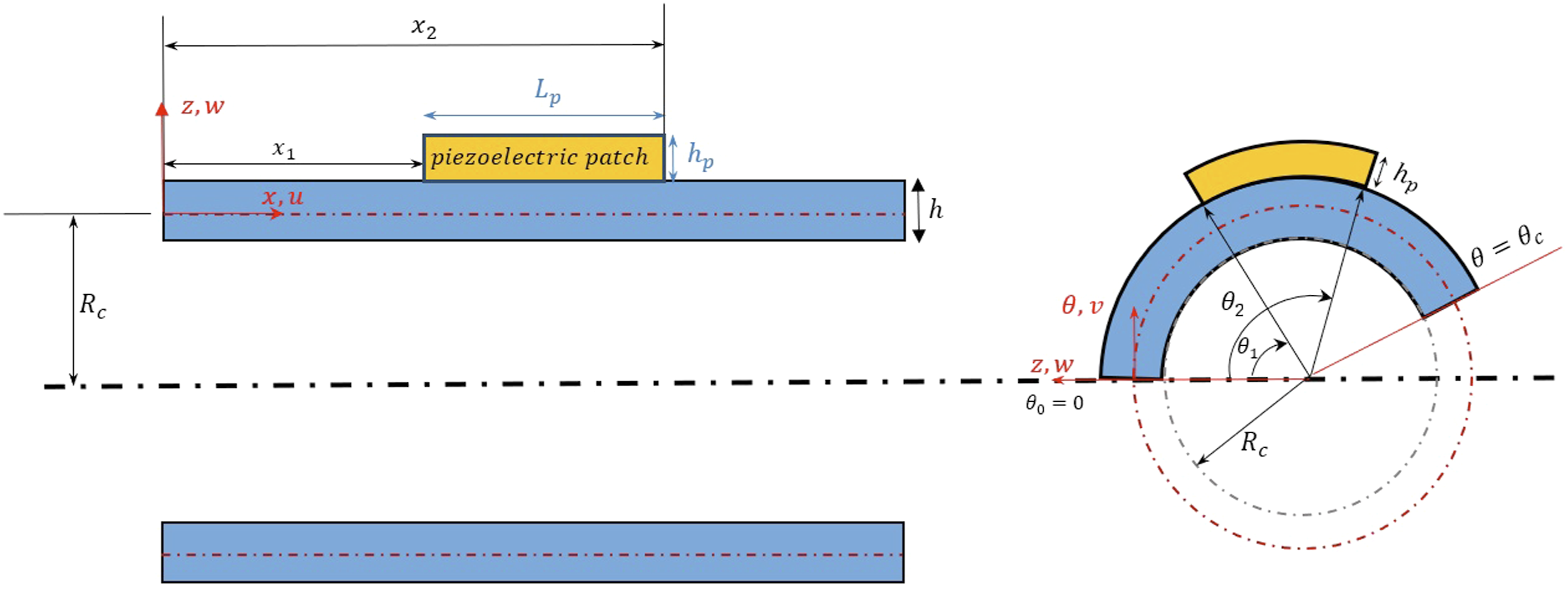
As the piezoelectric patch is always connected to the panel, the relations of the strain and displacement function of the panel also hold for the patch. Based on FSDT, the displacement function field of panel and patch are defined as follows (Reddy, 2006),

The strain relations for an arbitrary point on panel and patch are also formulated as,
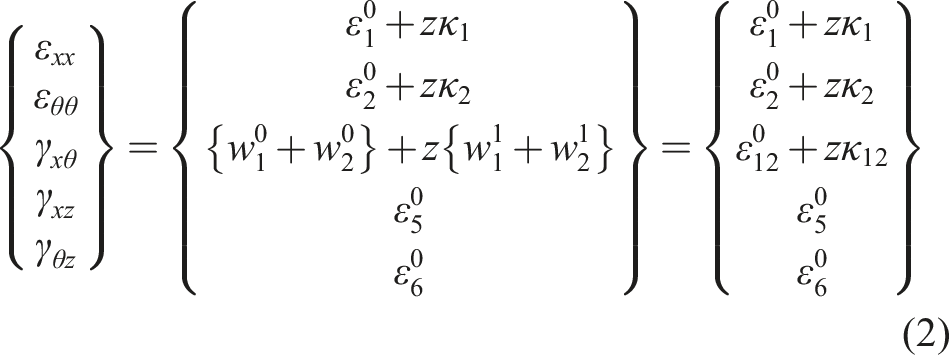
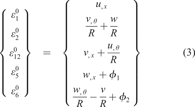
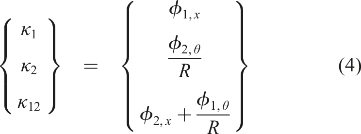
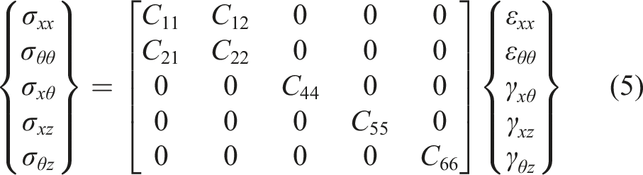
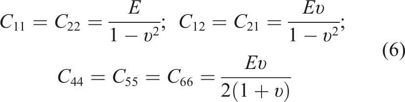
In this study, the cylindrical panel is considered as an isotropic panel. Therefore, the constitutive relations between stress and strain can be expressed as follows,


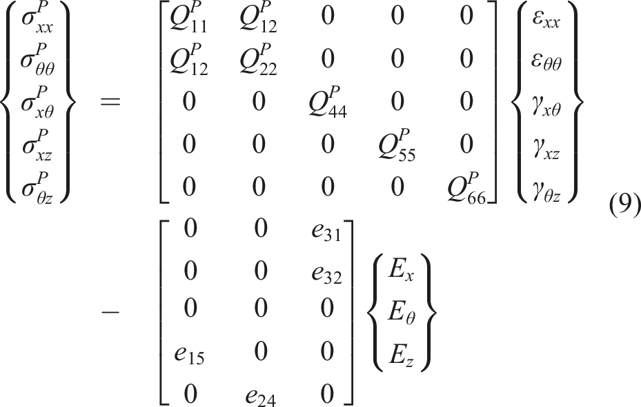
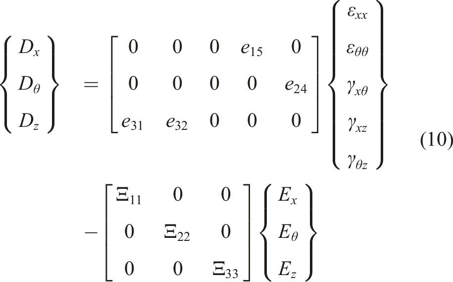






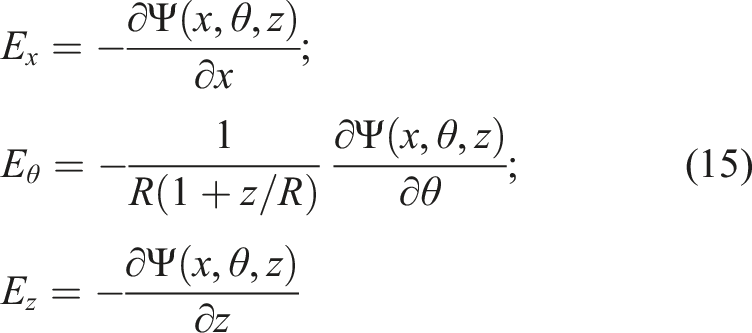
According to the piezoelectric constitutive equations, the electric field generated in the piezoelectric patch directly affects on the stresses. Furthermore, by knowing the electric potential generated within the piezoelectric material, the field in the piezoelectric patch can be calculated utilizing equations equations (14) and (15). In these equations, the function Ψ(x, θ, z) represents the electric potential, which can be determined based on the piezoelectric boundary conditions.

The piezoelectric patch is considered as a sensor, where the electric potential is generated due to elastic deformations caused by vibrations. The shell has no electric potential, also the bottom layer of the piezoelectric patch is connected to the panel/shell. Therefore, the bottom surface of piezoelectric patch must follow the same condition based on the compatibility requirement. Thus, the bottom layer of the piezoelectric patch must have zero electric potential, which known as grounding.
Furthermore, the top layer of piezoelectric condition are divided into two phases, namely, zero and non-zero potential. If both of top and bottom layer’s conditions are assumed ground condition, it will be represented as short-circuit condition. If the top layer will be fully isolated, the electrical displacement and voltage have zero and non-zero value, respectively. This condition will be represented open-circuit. The relations of short and open-circuit are defined as the following, for Short-circuit:


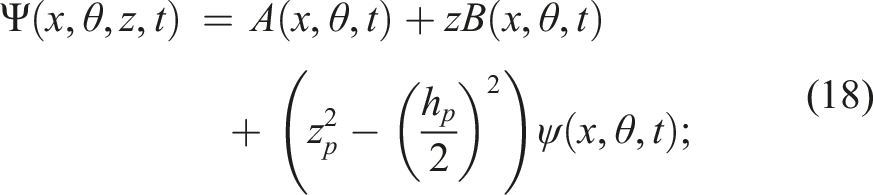
Assuming the electric potential function as follows Bodaghi and Shakeri (2012); Khorshidi et al. (2020),

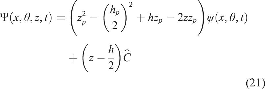
The electric potential function of the patch can be calculated by applying the boundary conditions from equation (17) into equation (18) as follows, for Short-circuit:


The resultant forces and moments in the cylindrical panel and shell are defined as follows,
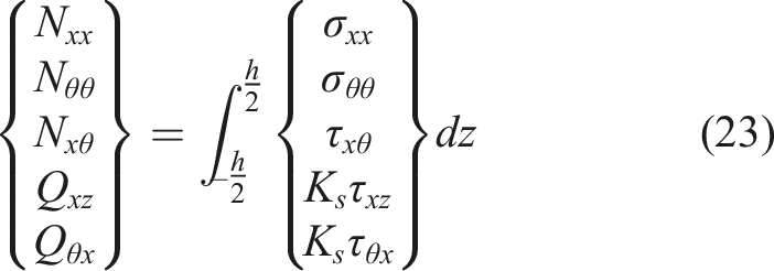
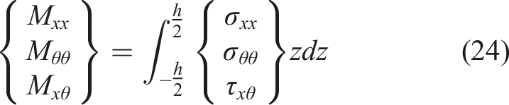
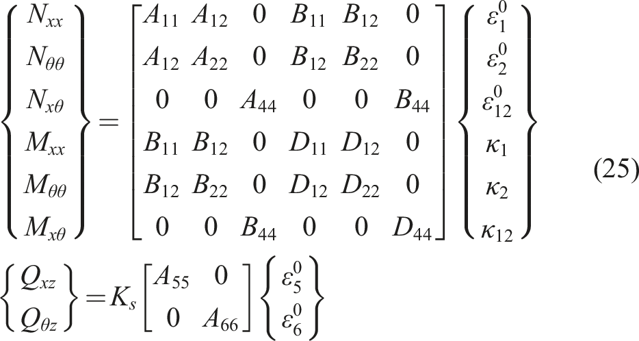
In the above equation, κ
s
is the shear correction factor, which is taken as 5/6. By substituting the stress values into the resultant forces and moments equations, they will be defined as follows,
By substituting Equation Equation (9) into Equations (23) and (24), the resultant forces and moments in the piezoelectric patch will be as follows,
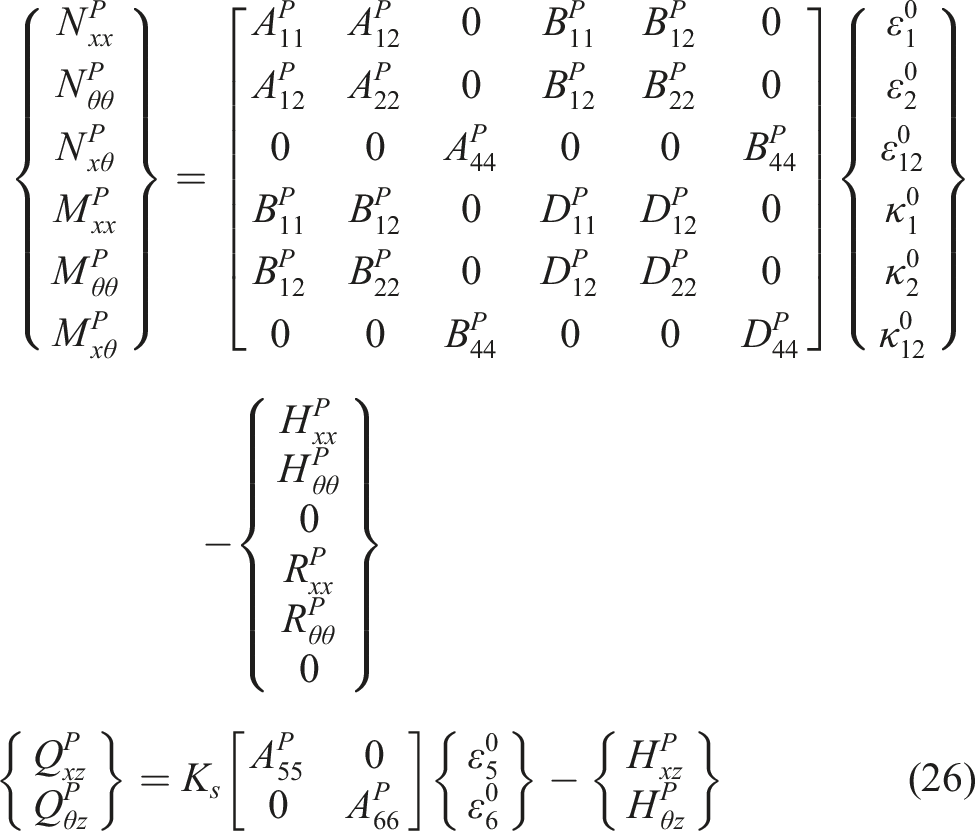




The matrix components of Equations (25) and (26) are obtained by integrating the stiffness matrices over the thickness direction as follows,


Moreover, the governing equations are derived using Hamilton’s principle, which is formulated as follows,

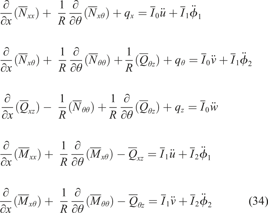
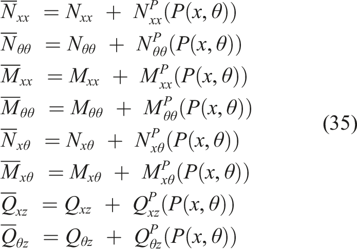
The
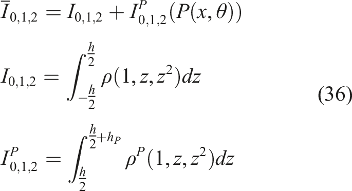
The superscript p in Equations (35) and (36) represents the piezoelectric portion. Additionally, the function P (x, θ) is defined as,

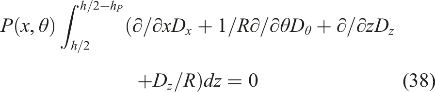
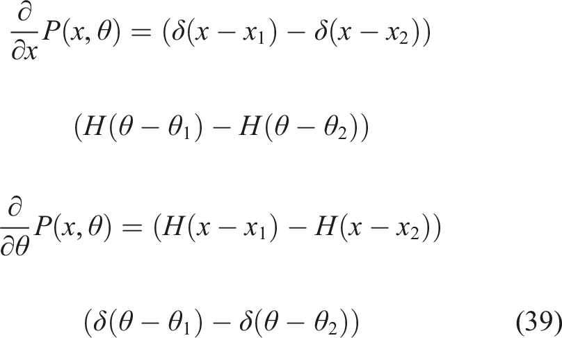
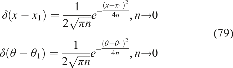
Therefore, in regions without piezoelectric material, the system consists of five coupled mechanical equations, while in regions with piezoelectric patches, it includes six coupled electromechanical equations, which must be solved simultaneously. It is important to note that the derivative of the Heaviside function with respect to the x and θ directions appears in the above equations, which corresponds to the Dirac delta function δ, defined as follows,
If the cylindrical panel is defined in the θ direction from 0 to 2π radians and the edges at 0 and 2π are joined, the cylindrical panel becomes a cylindrical shell. To ensure these two edges align, a compatibility condition must be applied at this boundary. The compatibility conditions are also applied to the piezoelectric patch. Specifically, if the piezoelectric patch is considered as a ring with edges at 0 and 2π, in addition to the mechanical compatibility conditions, electrical compatibility conditions must also be enforced between these two edges. Section. 2.2 will be represented the equations of boundary and compatibility condition.
2.2. Boundary and compatibility condition
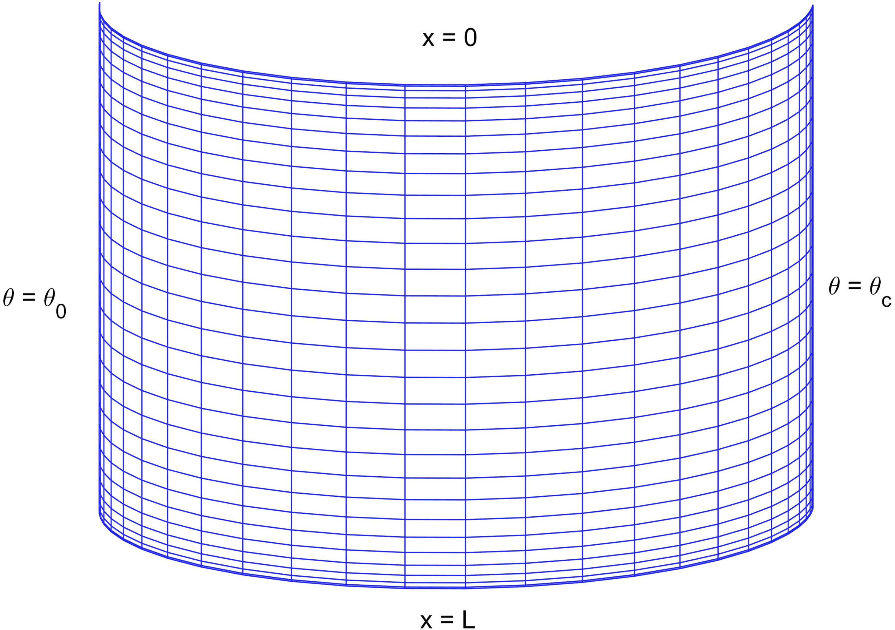
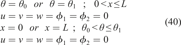
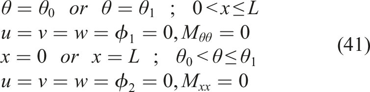
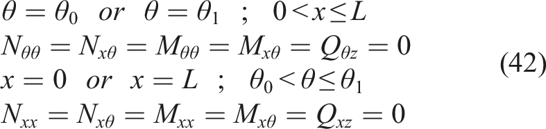
If the host structure with the piezoelectric patch is considered as a panel, it will have four edges, which has shown in Figure 2. Each of these four edges can be subjected to one of three mechanical boundary conditions: clamped (C), simply supported (S), or free (F). The mathematical expressions for these boundary conditions at each edge are defined as follows, 1. Clamp boundary condition 2. Simply support boundary condition 3. Free boundary condition Boundary conditions of cylindrical panels.
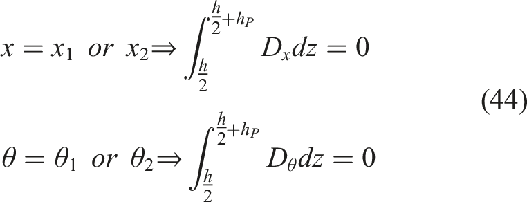
For the piezoelectric patch attached to the panel, the four edges can be subjected to electrical boundary conditions of either grounding or insulation. The mathematical expressions for these conditions are expressed as follows, 1. Ground condition 2. Insulation boundary condition

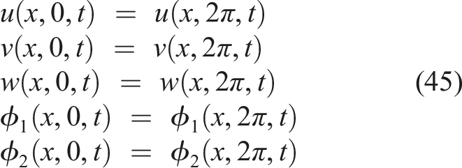
If the edges at θ = 0 and θ = 2π of the cylindrical panel are joined, transforming the panel into a complete cylindrical shell, compatibility conditions must be applied at these two edges instead of boundary conditions. These compatibility conditions are divided into two categories: displacement-based mechanical conditions and force-based mechanical conditions, which are defined as follows,
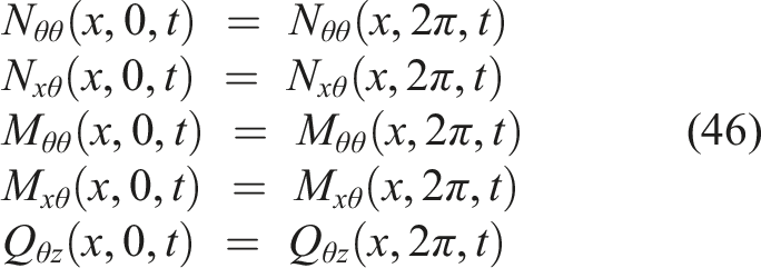
Additionally, if the patch is considered as a ring, after applying the mechanical compatibility conditions, the electrical compatibility conditions must also be imposed on the sixth equation of the system (Maxwell’s equation). Due to the alignment of the edges at θ = 0 and θ = 2π, the electric potential and electric displacements at this boundary must also be equal, just as the forces and displacements were equal at this interface.


3. Solution approach
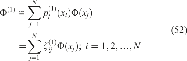
The partial differential equations and the boundary conditions as well as compatibility conditions will be discretized using the 2D–GDQ method. Therefore, the PDEs are transformed into a linear algebraic system of equations. Shu Shu (1991) developed the GDQ method to improve the Differential Quadrature (DQ) technique for calculating the weighting coefficients. DQ method is a technique which transforms the partial differential system of equations into the linear algebraic system of equations. According to this method, the partial derivative of a smooth function with respect to a variable is approximated by a weighted sum of function values at all discrete points in that direction. The weighting coefficients depend on the grid points, which is written with arbitrary grid distribution, and the derivative order. Shu Shu (2012) improved the DQ method based on analysis of linear vector space and high-order polynomial approximation. It is well known that a smooth function Φ(x) in the closed interval [a, b] can be accurately approximated by a high-order polynomial. Thus, if Φ(x) is the solution of a PDE, then it can be approximated by a polynomial which can be written as Motazedian et al. (2024),





The GDQ method can also be employed for bi variate functions such as Φ(x, y). Approximating the function of Φ(x, y) with respect to x and y to a polynomial allows us to calculate the n-order derivatives with respect to x and the m-order derivatives with respect to y of the function Φ(x, y) as follows,


The partial derivative with respect to both x and y is defined by equation (57).
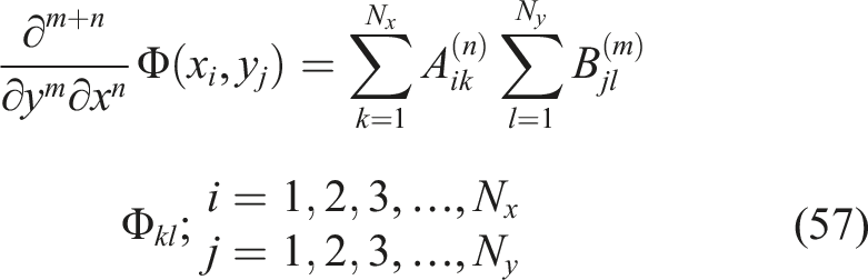
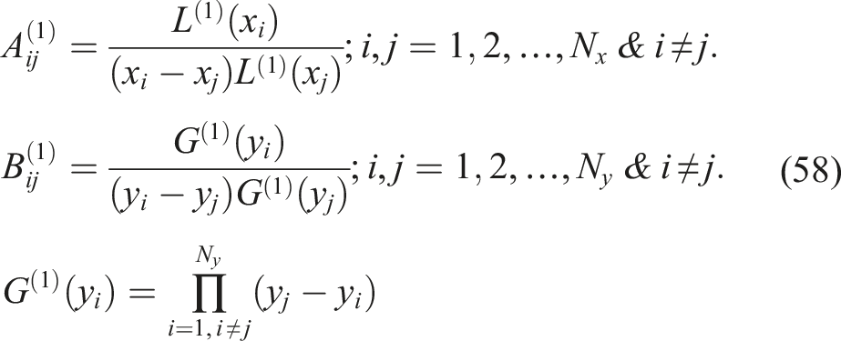
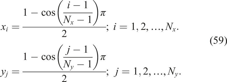
N
x
and N
y
are the number of grid points in the x and y domains, respectively. When i equals j the weighting coefficients matrix can be obtained as follows,
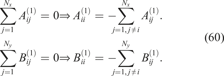
In addition, weighting coefficient matrix of the n
th
-order and m
th
-order derivative of the function


4. Numerical solution
After deriving the Navier equations of motion for the panels or shells, the 2D–GDQ method is employed to discretize the partial differential equations. During this process, internal and boundary points on the grid are distinguished, and the appropriate boundary and compatibility conditions are applied. Consequently, the simplified equations can be expressed as follows,



The ψ is the electric potential (voltage) of the piezoelectric patch. The equation (65) represents Maxwell’s equation. Separating the boundary and internal points of the grid Equations (63) and (65) is reformulated as follows,
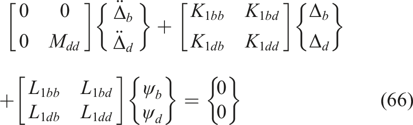
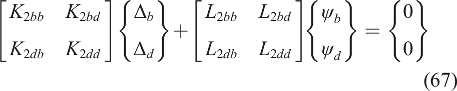
If the piezoelectric patch is located at the boundary, it interacts with the boundary nodes, causing the L
1bb
, L
1bd
, and L
1db
terms in equation (66) and the L
2bb
, L
2bd
, L
2db
, K
2bb
, K
2bd
, and K
2db
terms in equation (67) to be nonzero. Otherwise, if the piezoelectric patch isn’t located at the boundary, values of terms will be zero. In the following, the equation (67) can be rewritten as follows,
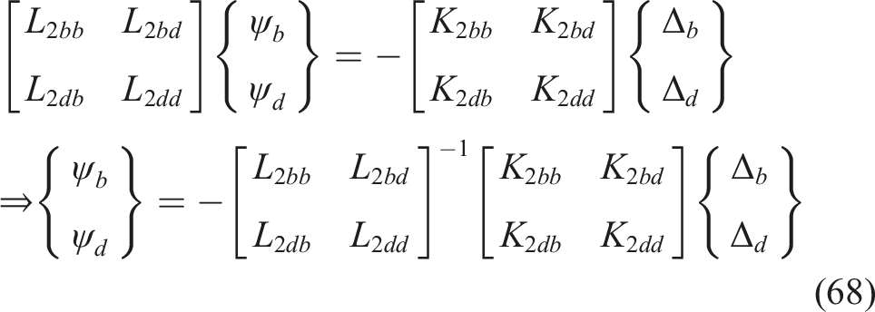
Therefore, equation (68) substitutes into equation (66) as follows,
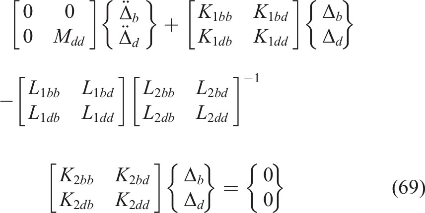
The equation (69) may be defined as follows,
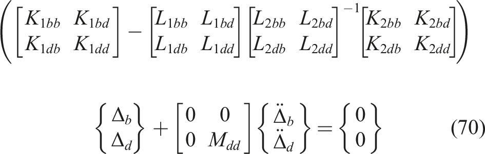

The equation (71) may be simplified as follows,


Substituting Δ
b
from equation (72) into equation (73) as,



In this study, the free vibration of shells will be investigated. Therefore, the displacement functions may be defined as follows,
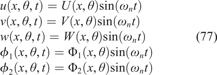
Substituting equation (77) into equation (72), the natural frequencies will be obtained as follows,

Due to the Chebyshev–Gauss–Lobatto point distribution and the non-uniform spacing between nodes, MATLAB software is unable to accurately detect the location of the patch using the Dirac delta function, rendering the implementation of the 2D–GDQ method impractical. Consequently, an approximation of the Dirac delta function must be used Eftekhari (2016). Various functions have been proposed for this purpose, with the approximation adopted in this study given by Equation (79). In practice, wherever the Dirac delta function appears in the equations, it is replaced by the approximation in Equation (79).
5. Results and discussions
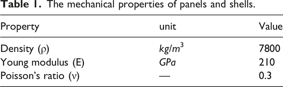
The mechanical properties of panels and shells.
The mechanical properties of piezoelectric of PZT–4.
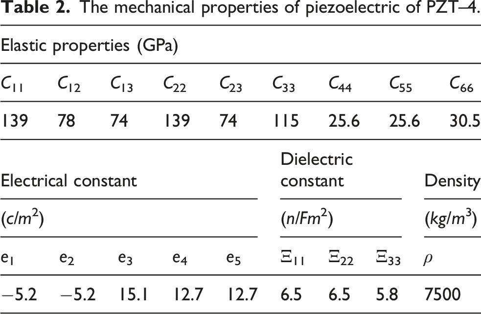
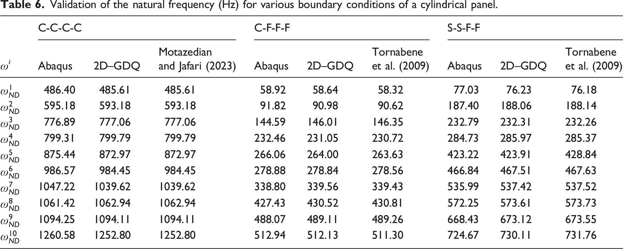
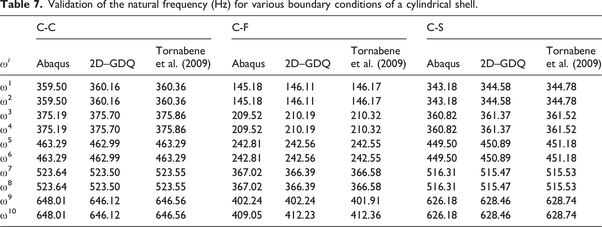
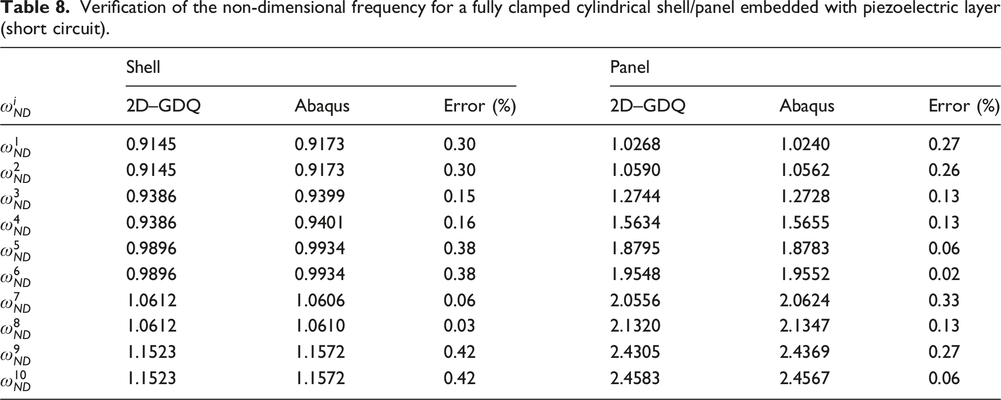
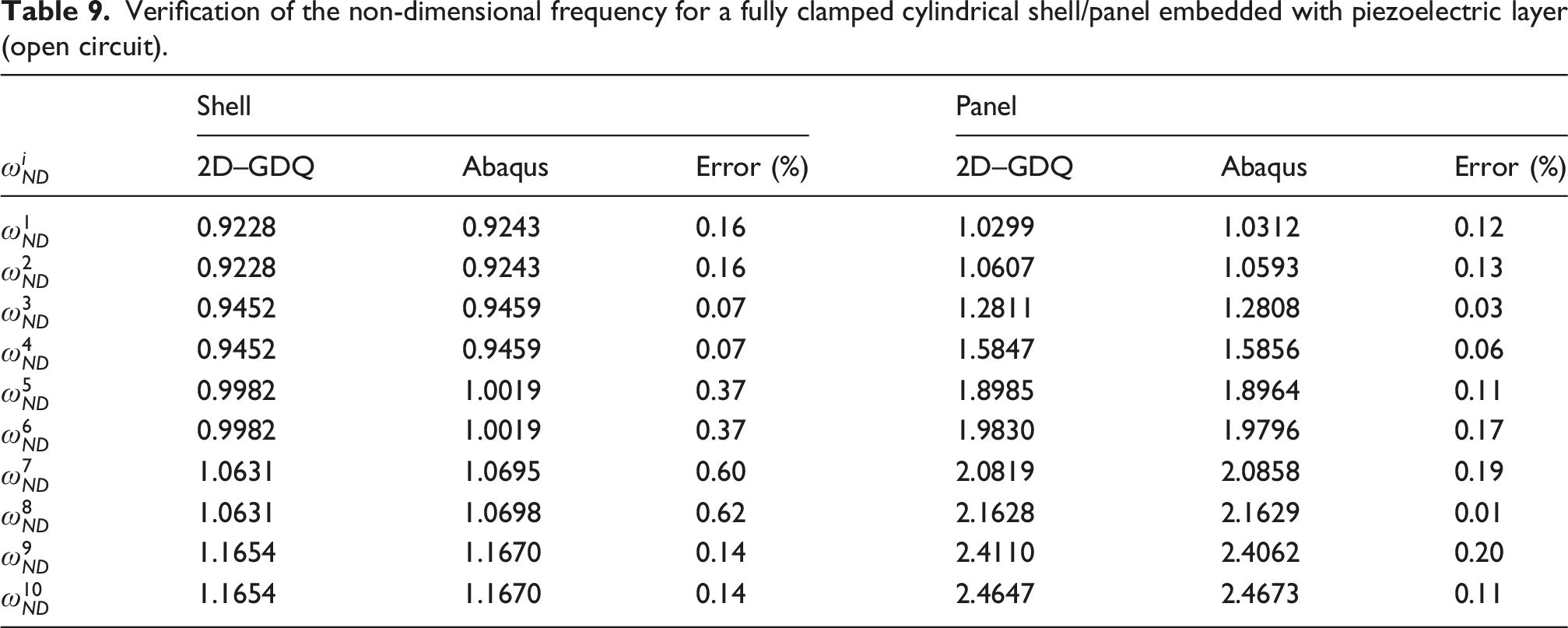
In order to verify the results, the finite element software Abaqus is also utilized. The piezoelectric patch is modeled as a solid part, with the piezoelectric element type specified as C3D20RE, a 20-node element applied to the piezoelectric patch. The model was analyzed using a 3D stress formulation with C3D20 R elements. The term “3D stress element” refers to a three-dimensional continuum element. Also, The C3D20 R is a 20-node quadratic brick solid element with reduced integration. Tie constraint is employed to model the connection between the panel and the piezoelectric patch. Finally, the natural frequencies of the system are extracted using the frequency solver from the Linear Perturbation module. Mesh convergence studies were conducted for all dimensions and geometries analyzed in Abaqus, and the reported frequencies are independent of the mesh size and number.
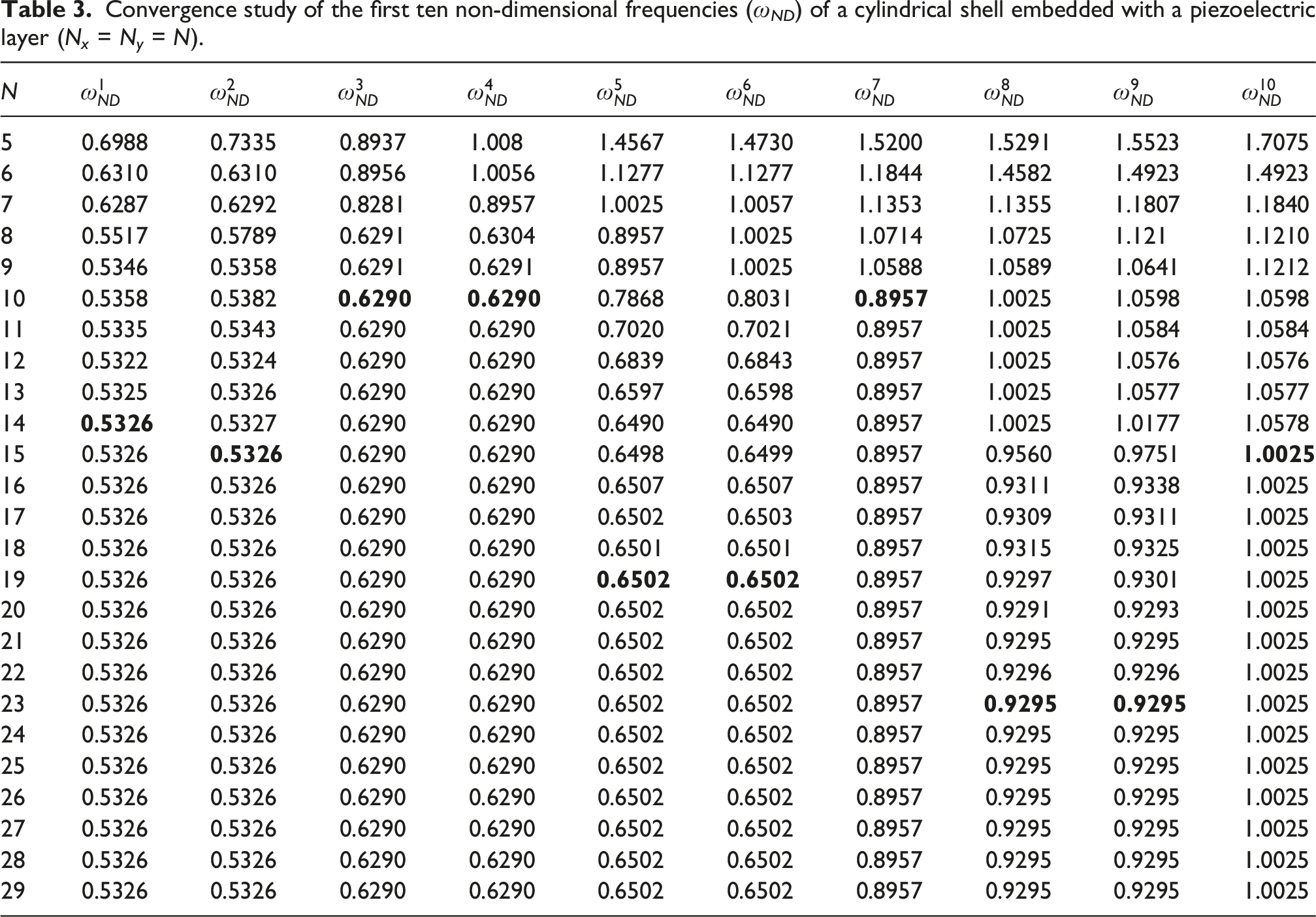
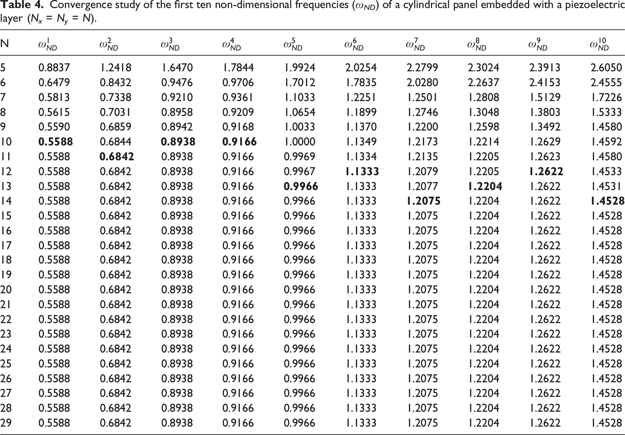
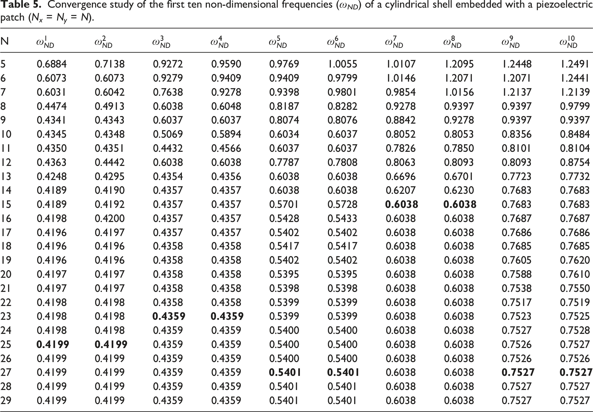
5.1. Convergence

Convergence study of the first ten non-dimensional frequencies (ω ND ) of a cylindrical shell embedded with a piezoelectric layer (N x = N y = N).
Convergence study of the first ten non-dimensional frequencies (ω ND ) of a cylindrical panel embedded with a piezoelectric layer (N x = N y = N).
Convergence study of the first ten non-dimensional frequencies (ω ND ) of a cylindrical shell embedded with a piezoelectric patch (N x = N y = N).
5.2. Verification
Validation of the natural frequency (Hz) for various boundary conditions of a cylindrical panel.
Validation of the natural frequency (Hz) for various boundary conditions of a cylindrical shell.
Verification of the non-dimensional frequency for a fully clamped cylindrical shell/panel embedded with piezoelectric layer (short circuit).
Verification of the non-dimensional frequency for a fully clamped cylindrical shell/panel embedded with piezoelectric layer (open circuit).
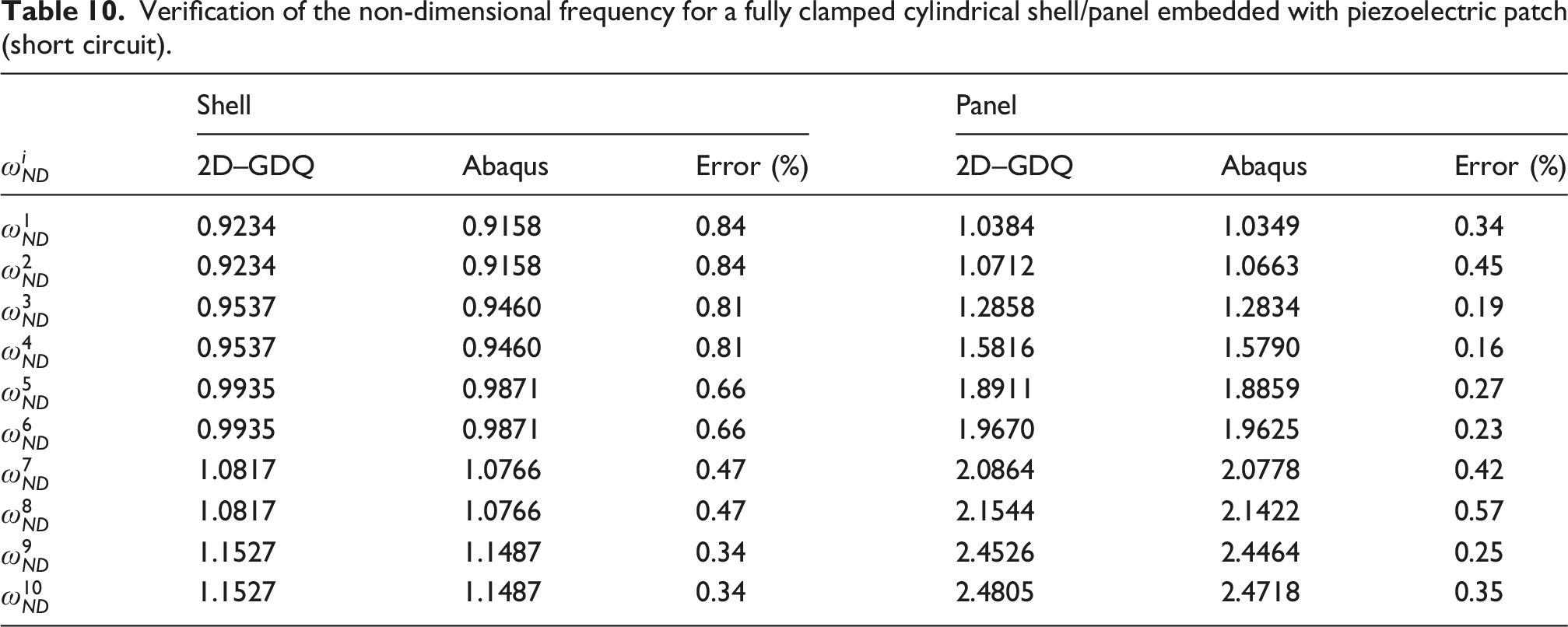
Verification of the non-dimensional frequency for a fully clamped cylindrical shell/panel embedded with piezoelectric patch (short circuit).
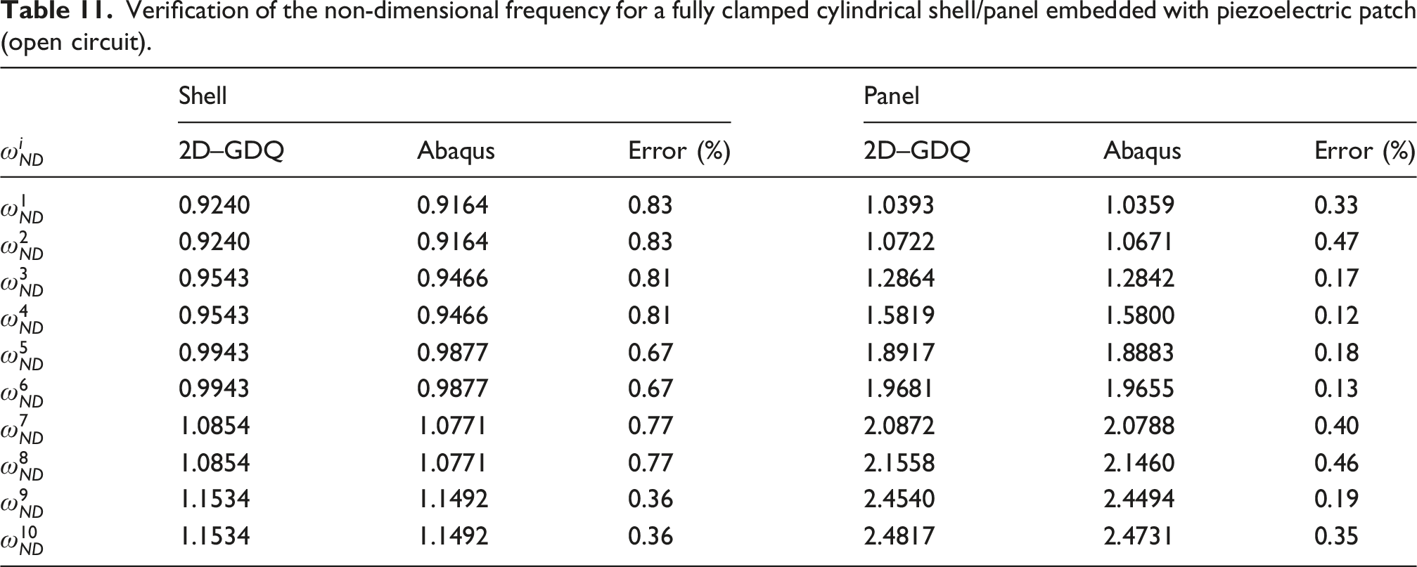
Verification of the non-dimensional frequency for a fully clamped cylindrical shell/panel embedded with piezoelectric patch (open circuit).
5.3. Parametric studies
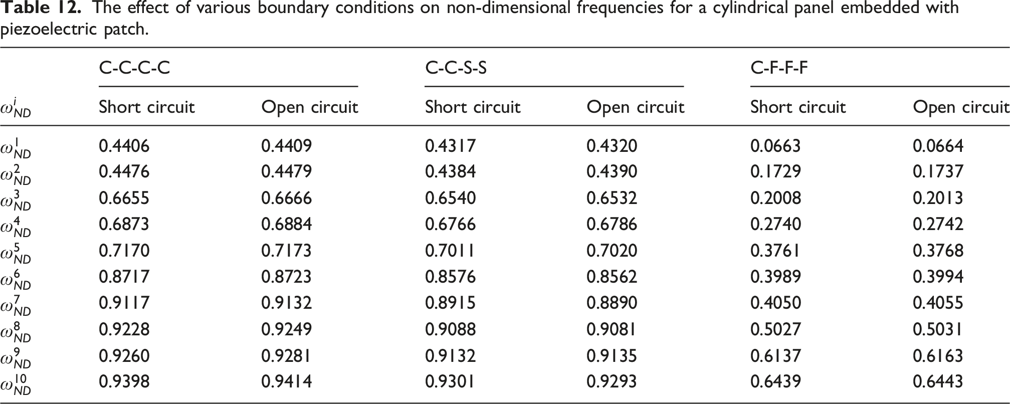
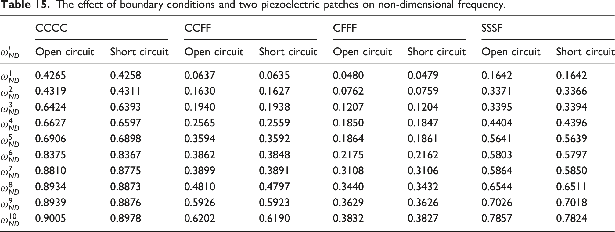
The effect of various boundary conditions on non-dimensional frequencies for a cylindrical panel embedded with piezoelectric patch.
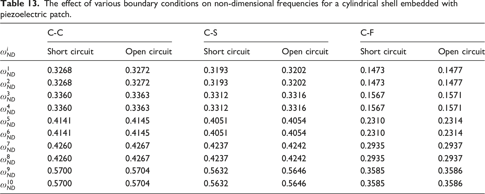
The effect of various boundary conditions on non-dimensional frequencies for a cylindrical shell embedded with piezoelectric patch.
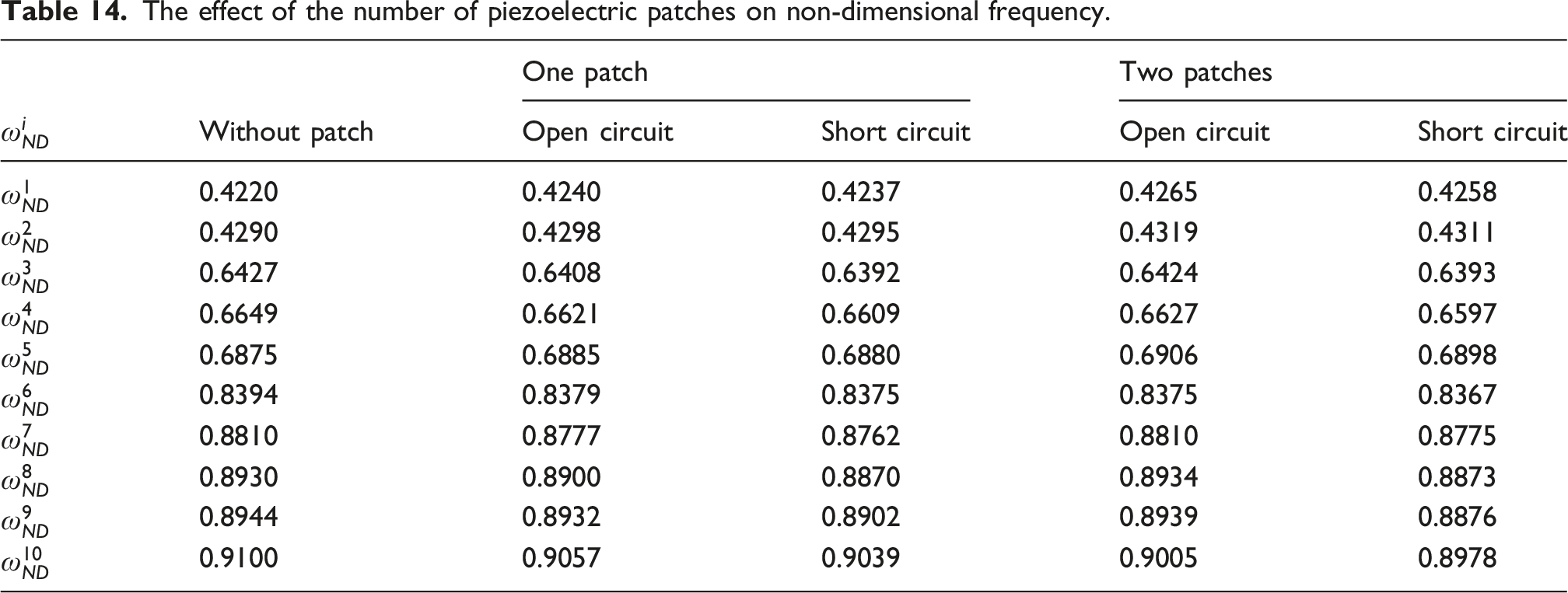
The effect of the number of piezoelectric patches on non-dimensional frequency.
The effect of boundary conditions and two piezoelectric patches on non-dimensional frequency.
In addition, effective geometry parameters of piezoelectric patch on natural frequencies of cylindrical shell are investigated. Figure 3 indicates the variations thickness of piezoelectric patch. An increase in the thickness of the piezoelectric patch generally results in a decrease in the system’s natural frequency. This behavior suggests that the thickness predominantly influences the mass matrix, therefore increasing the value of inertia and leading to a reduction in natural frequency. The effect of h
p
/h on non-dimensional frequencies of cylindrical panel embedded with piezoelectric patch.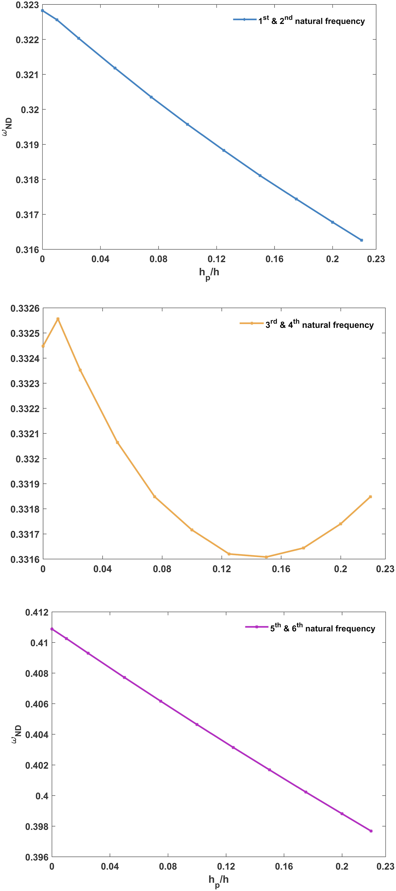
Furthermore, the variation of the natural frequency with an increase in the length of the piezoelectric patch is shown in Figure 4. Based on the results, the value of natural frequencies initially increasing and subsequently decreasing. The determination of the system’s natural frequency involves the interplay between the mass and stiffness matrices. The relative influence of the patch length on these matrices dictates the observed behavior, where the frequency trend can shift from increasing to decreasing depending on the dominant effect. The effect of L
p
/L on non-dimensional frequencies of cylindrical panel embedded with piezoelectric patch.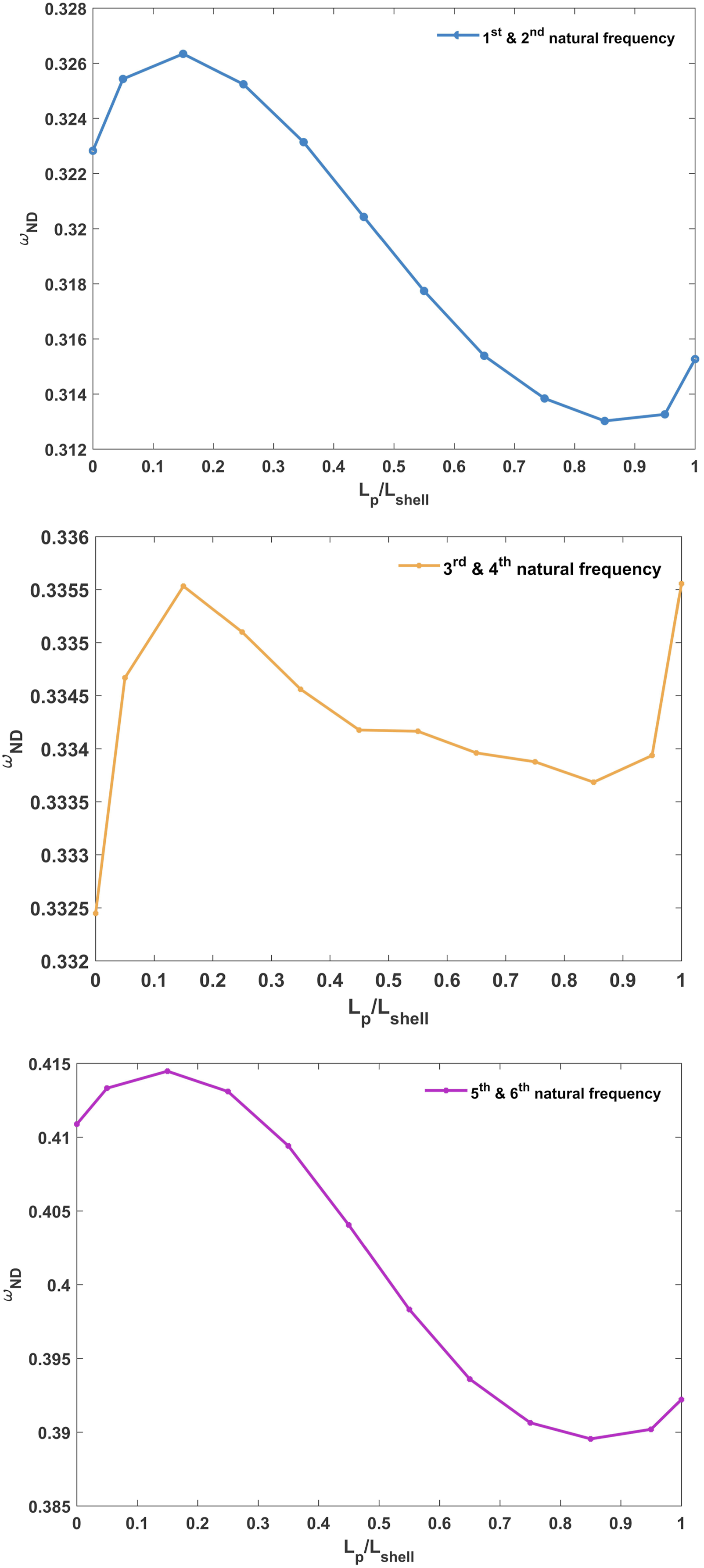
The effect of θ of the piezoelectric patch can also be observed in Figure 5, where an increase in θ results in a decrease in the natural frequency. This suggests that an increase in θ raises the system’s inertia, which consequently leads to a reduction in the natural frequency. The effect of θ
p
/360° on non–dimensional frequencies of cylindrical panel embedded with piezoelectric patch.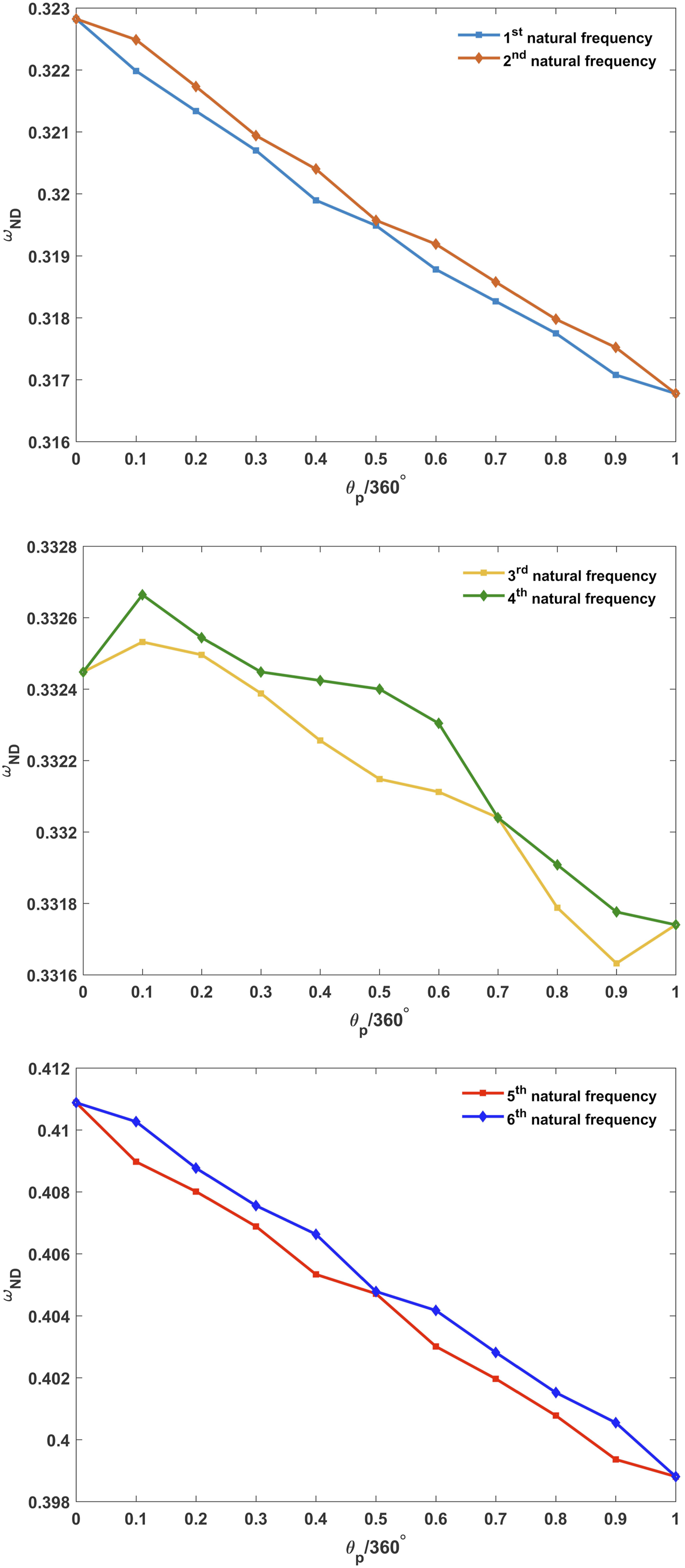
6. Conclusion
In this study, the free vibration of cylindrical shell/panel embedded with piezoelectric patch is investigated. The equations of motion of cylindrical shell are derived by utilizing the FSDT and Hamilton’s principle. Also, Maxwell equations are considered to model the piezoelectric patch. The 2D–GDQ method is employed to discretize the PDEs into ODEs. In addition, the Harmonic response is considered to solve eigenvalue problem to obtain the natural frequencies. The effect of various parameters on dynamic behavior of cylindrical shell/panel embedded with piezoelectric patch are studied, which vital results are provided as follows, • According to the results, changing the geometry of piezoelectric material from patch to layer can be affected on the number of grid points for converging the natural frequencies. The geometry of cylindrical shell or panel is also effective on convergence of grid points. • The boundary conditions of cylindrical shell, which embedded with piezoelectric material, can be effected on value of natural frequencies. The fully clamped boundary condition and open-circuit condition have the highest value of natural frequencies. • An increase in the value of θ in the piezoelectric patch generally leads to an increase in the system’s inertia, which consequently results in a decrease in the natural frequency. • Increasing the thickness of the piezoelectric patch can also generally lead to an increase in the system’s inertia, which consequently results in a decrease in the system’s natural frequency. • The natural frequency of the system initially increases and then decreases with an increase in the length of the piezoelectric patch. • An increasing the number of piezoelectric patches from one to two leads to increase the value of natural frequency.
Footnotes

Funding
The authors received no financial support for the research, authorship, and/or publication of this article.
Declaration of conflicting interests
The authors declared no potential conflicts of interest with respect to the research, authorship, and/or publication of this article.