
Abstract
Load swing suppression remains a critical challenge in underactuated crane systems, especially when arbitrary initial oscillations and strict sway constraints are involved. This paper proposes an enhanced zero vibration constraint command shaping (EZVCCS) method to address this problem. The method explicitly incorporates swing constraints into the shaping process, enabling precise trajectory planning while ensuring terminal state satisfaction. A systematic investigation examines the effects of maneuvering time, velocity constraints, input step number, and sway constraints on system performance. The EZVCCS method supports arbitrary initial and terminal conditions, unlike the traditional ones. This allows maneuvers that are flexible point-to-point even in cases where the sway requirement is stringent. Moreover, it unifies and extends existing command shaping strategies: with a small input step number, it reproduces the acceleration characteristics of zero-vibration (ZV) and zero-vibration-derivative (ZVD) shapers, while delivering improved suppression of initial sway and guaranteed terminal-state accuracy under the imposed constraints. With larger step numbers, the piecewise-constant command attains finer shaping resolution and can closely approximate the closed-form command shaping (CFCS) method, while the embedded constraints enable stricter sway regulation. Overall, the EZVCCS method offers a unified solution that balances sway suppression and computational efficiency, demonstrating strong potential for practical crane applications.
Keywords
1. Introduction
In industrial applications, crane motions from zero or non-zero initial states to a zero final state have been extensively investigated (Abdel-Rahman et al., 2003; Ramli et al., 2017; Singhose, 2009; Tayefi and Geng, 2018). However, many practical tasks require transitions from arbitrary initial states to non-zero final states, which have received far less attention. Most existing studies are constrained to the traditional assumption of motion from an initial zero state to a final zero state, thereby limiting their applicability to more general operational scenarios. To broaden the scope of engineering applications, especially in tasks involving precise positioning and load posture adjustment, it is crucial to develop motion control strategies that can handle arbitrary initial and final states, thereby improving the versatility and performance of crane systems.
A wide range of control methods for overhead cranes have been proposed in the literature. These approaches, whether open-loop or closed-loop, can generally be classified into three categories based on the initial and final states of the load swing: (i) zero initial to zero final state, (ii) arbitrary initial to zero final state, and (iii) arbitrary initial to arbitrary final state. To date, the majority of research has focused on the zero initial state to zero terminal state scenario. In the open-loop control method, input shaping has attracted extensive attention due to its advantages of no sensors and easy implementation. Representative studies include the adaptive unit-amplitude shaper (Maghsoudi et al., 2019), the fixed output response method (Alfares and Alhazza, 2024), and output-based command shaping (Abdullahi et al., 2017), which improve adaptability to time-varying lifting processes through online parameter adjustment, system transformation, and output feedback, respectively. Related multi-step command-shaping strategies have been reported for suspended liquid-container transport to suppress multimodal sloshing while improving robustness to parameter variations (Alshaya and Alghanim, 2020; Alshaya and Alshayji, 2022; Alshaya et al., 2025). These studies further motivate the use of multi-step shaping concepts in suspended-load systems beyond conventional payload swing control. In the closed-loop control method, various strategies have been introduced to improve anti-disturbance capability and robustness. Examples include neural networks (Ramli et al., 2018; Wang et al., 2024; Yang et al., 2019; Zhang et al., 2024a), sliding mode control (Guo et al., 2023; Nguyen et al., 2024; Suksabai and Chuckpaiwong, 2023; Zhang et al., 2024b; Zheng and Xu, 2025), adaptive algorithms (Abdullahi et al., 2018; Ouyang et al., 2021; Sun and Ouyang, 2022; Yao et al., 2024b; Yao and Hu, 2024), active disturbance rejection control (Huang et al., 2025a), and dynamic output feedback (Cao et al., 2025), all of which effectively mitigate the challenges of parameter variation, external disturbances, and input constraints. Additionally, methods targeting complex scenarios, such as PD sliding mode control for double-pendulum dynamics (Li et al., 2025) and multi-axis S-curve trajectory generation (Kudara et al., 2025), have significantly improved trajectory tracking accuracy and operational safety.
In practical cargo transport, the load is not always directly beneath the trolley, leading to frequent non-zero initial states. Compared with the well-studied zero initial state to zero final state motion, research on non-zero initial to zero final state transitions is more critical but relatively scarce. Existing work can be broadly divided into open-loop trajectory planning and closed-loop feedback control. In open-loop control, generalized zero vibration with non-zero initial conditions shaper (Huang et al., 2024; Mohammed et al., 2021) and multi-objective optimization methods (Mohammed et al., 2023) have been proposed to handle arbitrary initial states and large swing angles. Other approaches, such as trajectory generation based on dynamic programming (Jebellat and Sharf, 2024) and state-separation strategies (Uchida et al., 2024), have enabled precise path tracking and vibration suppression under complex conditions. In closed-loop control, error-tracking schemes (Zhang et al., 2017), neural-network-based adaptive shaping (Ramli et al., 2020), fuzzy adaptive nonlinear control (Miao et al., 2022), sliding mode control optimized by improved honey badger algorithm (Wang et al., 2023), and PID neural network control (Syazwin et al., 2024) have been developed to address uncertainties and external disturbances, showing strong robustness under non-zero initial conditions.
Despite these advances, research addressing maneuvers from arbitrary initial to arbitrary terminal states remains extremely limited. To the best of our knowledge, the closed-form command shaping (CFCS) method is the only existing approach that explicitly addresses such scenarios (Alhazza et al., 2022; Huang et al., 2025b). By analytically deriving shaper parameters, the CFCS method can suppress vibrations under non-zero initial states and enforce predetermined non-zero terminal states. While its effectiveness has been demonstrated through numerical simulations and experimental studies, the method lacks the rigor of maximum velocity constraints and the requirement to satisfy maximum swing constraints.
To comprehensively address the demands of practical operations, this paper proposes an enhanced zero-vibration constrained command shaping method (EZVCCS) for anti-sway control under arbitrary initial and terminal states. The proposed scheme systematically investigates the effects of maneuvering time, velocity constraints, and input step number on sway behavior, both with and without maximum swing constraints. The method is experimentally validated on a crane test platform and compared with the zero vibration (ZV), zero vibration constraint (ZVD), and CFCS methods. The results show that it has excellent sway suppression performance under various conditions. The main advantages of this method are summarized as follows: (1) Constraint-embedded multi-step command shaping via convex quadratic program (QP). We formulate the command-shaping design as a convex quadratic program in which swing-related requirements and motion limits are expressed explicitly as linear equalities/inequalities. This provides a systematic way to generate feasible multi-step acceleration commands and to verify constraint satisfaction within the adopted model over the maneuver horizon. (2) Systematic treatment of arbitrary initial and terminal states. The proposed framework explicitly incorporates nonzero initial conditions and prescribed terminal requirements within a single optimization-based shaping procedure. By adjusting the number of input steps, the command parameterization can be flexibly refined, enabling point-to-point maneuvers under explicit constraints in scenarios where classical rest-to-rest shapers are not directly applicable. (3) Unified and broadly applicable framework. With a small number of steps, the synthesized command preserves the characteristic multi-pulse structure of classical ZV/ZVD-type shapers, while explicitly accommodating non-zero initial conditions and prescribed terminal requirements. As the step number increases, the piecewise-constant command progressively approximates continuous-waveform shaping strategies (e.g., the CFCS method) with finer temporal resolution. This step-scalable formulation offers a practical trade-off between shaping fidelity and implementation complexity, and supports constrained trajectory planning across a wide range of crane operating conditions.
The remainder of this paper is structured as follows. Section 2 introduces the crane system model. Section 3 details the design of the proposed controller. Section 4 presents the numerical simulations and experimental validations. Finally, Section 5 summarizes the main conclusions and outlines directions for future research.
2. System modeling
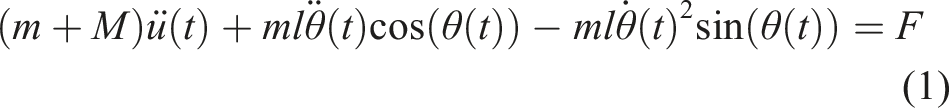
In this study, a simplified overhead crane system is modeled as a single-pendulum model, as illustrated in Figure 1. The motion is confined to the xy-plane, where the control input is defined as the trolley acceleration and the payload moves along the x-direction. By applying the Euler–Lagrange formulation, the governing equations of motion for the pendulum-type overhead crane can be expressed as (Lei et al., 2023; Mojallizadeh et al., 2023; Yao et al., 2024a) Schematic diagram of a simple pendulum model of the overhead crane.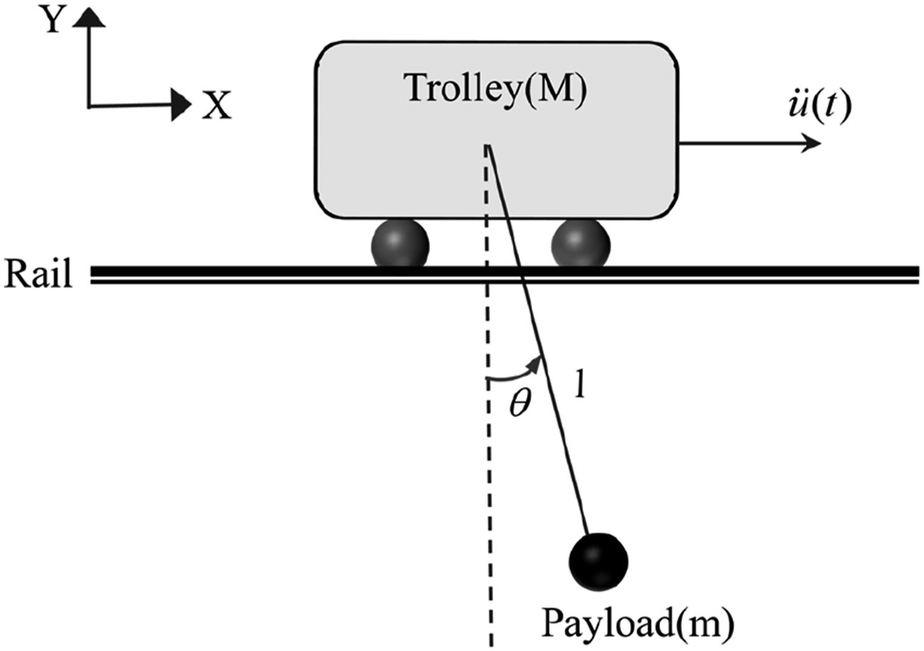

Equation (2) can be simplified as
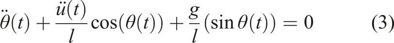
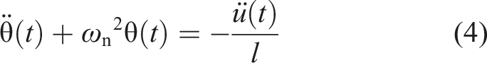
Since that the payload oscillation remains within a small-angle range during the maneuver,
To facilitate the derivation and design of the proposed EZVCCS method, while explicitly addressing challenges associated with non-zero initial conditions and state constraints, the following assumptions are introduced.
Assumption 1
(i) The payload swing is restricted to planar motion and remains within a bounded small-angle regime, that is, (ii) The cable length is known and remains constant during a point-to-point maneuver. Moreover, the initial swing state is assumed to be measurable before generating the shaping command. (iii) The trolley acceleration
These assumptions are widely adopted in the literature on open-loop trajectory planning for crane systems (Abdullahi et al., 2017; Alfares and Alhazza, 2024; Alhazza et al., 2022; Maghsoudi et al., 2019; Majeed et al., 2025; Uchida et al., 2024). The first assumption is reasonable since the proposed controller is explicitly designed to enforce the constraint
3. Controller design and main results
In this section, the EZVCCS method is developed to regulate trolley motion and suppress payload oscillations, ensuring that the crane system state is precisely characterized and effectively controlled. Based on the load swing angle and angular velocity, as well as the trolley displacement and velocity, an extended state vector

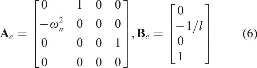
To construct the command shaping input, the trolley acceleration

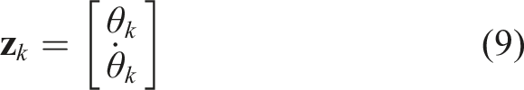
Define the state of swing and swing velocity as
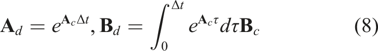
Based on the superposition principle of linear time-invariant systems, the analytical solution of the system state at time k can be obtained by superimposing the free response due to the initial conditions and the forced responses resulting from all past control inputs. The corresponding expression is given as follows
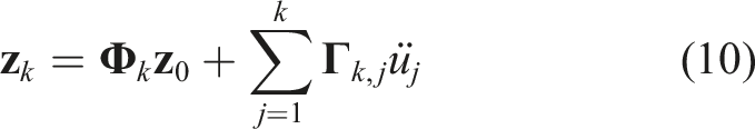
Given the initial conditions
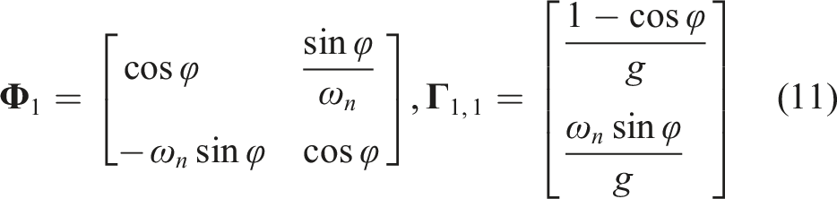
The recursive formula for

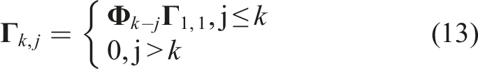
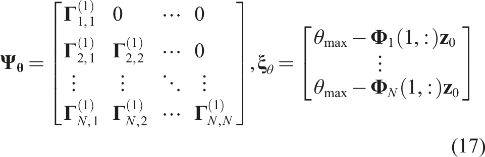
The inequality constraints governing the system operation can be expressed as
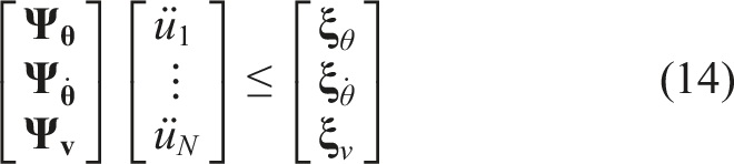

The swing of payload is constrained by

Similarly, the velocity of swing is bounded as

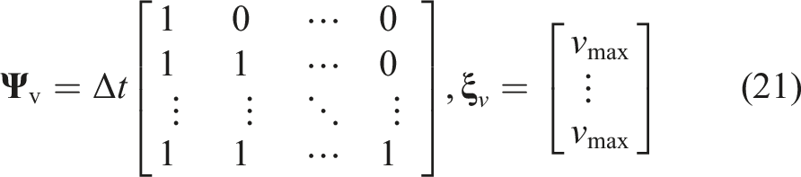
The constant-velocity constraint is introduced to explicitly enforce the operational bound on trolley speed and to improve feasibility under practical motion limits. It prevents overly aggressive acceleration profiles that may satisfy terminal conditions but violate speed limits. The velocity constraint of the trolley is given by

The terminal trolley displacement can be expressed as
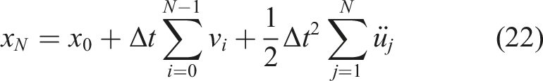
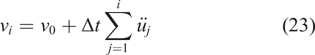
Substituting equation (23) into equation (22) and collecting terms with respect to each
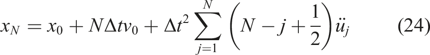
Accordingly, we define the displacement-row coefficient as
The constraint set is convex because it is an intersection of linear inequality constraints.

The intersection of linear inequalities forms a convex set, and hence the constraint set is convex.
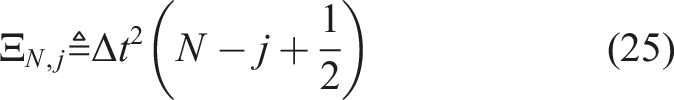
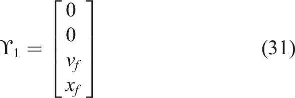
At the end of operation, the system must satisfy the following terminal conditions
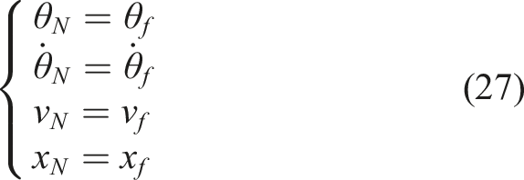
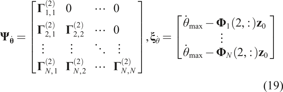
The corresponding constraint matrix of the system can be written as
Let

Based on the system dynamics, the operation process can be divided into three stages: acceleration, cruise, and deceleration. The specific constraints for each stage are summarized as follows.
When

When

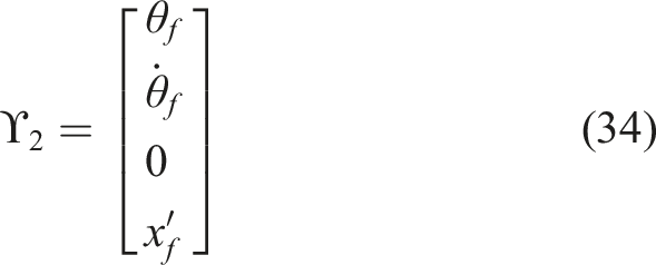
With the state transition expressed as

When
To solve the problem, convex optimization techniques are employed. The QP problem can be written in the standard form as
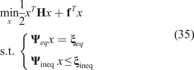
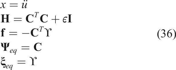
Here
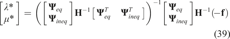
For a given QP, the optimal solution must satisfy the Karush–Kuhn–Tucker (KKT) conditions
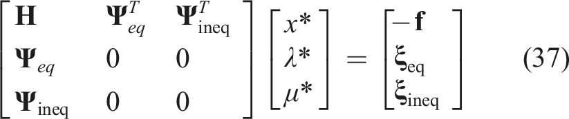
By solving the inverse of the block matrix, we obtain

Thus, the input acceleration signal satisfying the swing suppression constraints can be systematically determined under different operating phases, thereby enabling the design of an effective anti-sway control strategy for overhead cranes. Furthermore, the proposed framework can be readily adapted to fully exploit the maximum input capabilities of the driving motors. By explicitly incorporating an acceleration bound into the inequality constraints in equation (15) and iteratively minimizing the maneuver time, the optimization solver inherently drives the command to the actuator’s physical limits, thereby achieving fast, time-optimal maneuvers.
4. Simulation and experimental results discussion
This section evaluates the effectiveness of the proposed EZVCCS method via numerical simulations and experiments. In the simulations, continuous-time system responses were generated using the ode45 solver in MATLAB R2023b. The optimized acceleration command was implemented as a zero-order-hold (ZOH) input with a sampling interval
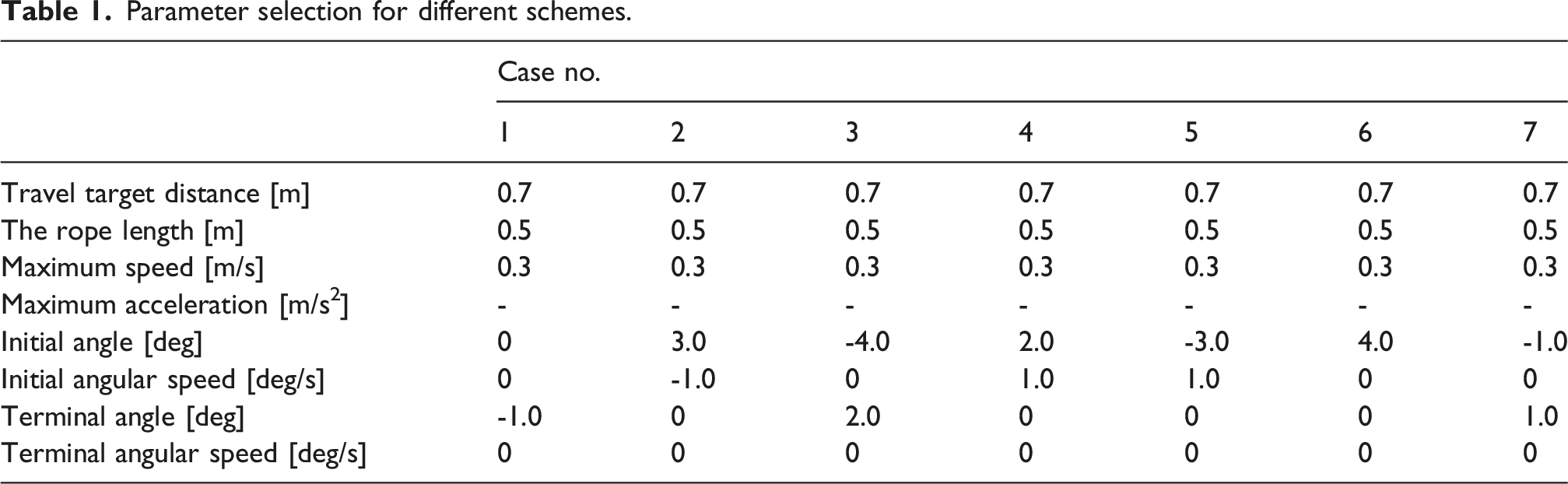
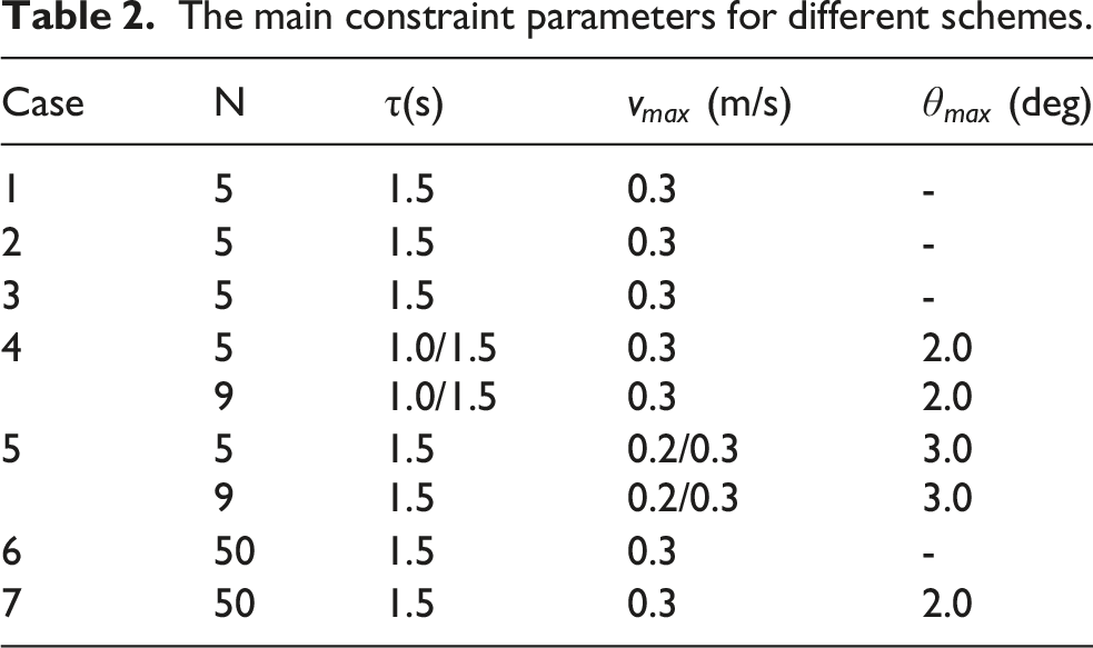
To further demonstrate the generality of the method, additional cases with non-zero initial swing velocity are also investigated. The experimental studies are performed on a scaled-down overhead crane test platform, as illustrated in Figure 2. The parameter sets in Tables 1–2 were selected to match the physical limits and typical operating range of the laboratory crane platform, while covering representative combinations of initial/terminal swing states, velocity bounds, maneuver times, and swing constraints. Overhead crane experimental test platform. Parameter selection for different schemes. The main constraint parameters for different schemes.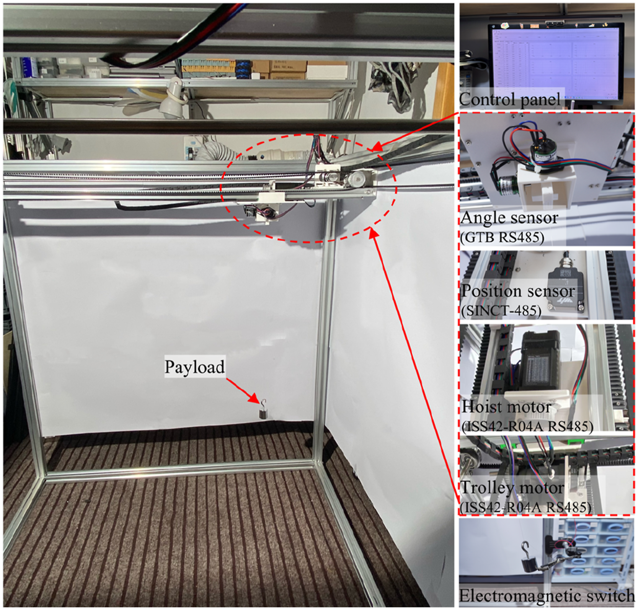
From the modeling perspective, payload swing is primarily induced by the trolley acceleration input, which highlights the critical role of acceleration control. As shown in the controller design and analysis presented in Section 3, the acceleration input is determined by several key factors, including the maneuver time, velocity constraints, number of input steps, and the swing constraint. To clarify their influence on the swing response, two groups of studies were conducted: (1) Unconstrained case: the effects of maneuver time, velocity constraints, and number of input steps are examined individually without imposing swing constraints. (2) Constrained case: the combined influence of maneuver time, velocity constraints, and number of input steps is analyzed under the swing angle constraint.
The selected parameters for these analyses are provided in Table 2. The subsequent subsections present detailed simulation and experimental results for these two cases, followed by a comparative discussion.
4.1. Study without swing constraints
Under nominal operating conditions, maximum swing constraints may not be strictly required. In such cases, the swing constraint can be omitted from the optimization problem. We investigated swing responses under different initial and terminal conditions, with varying maneuver times, velocity constraints, and numbers of input steps. For instance, an initial swing of −1 degree with zero initial swing velocity was selected, while both the terminal swing and swing velocity were set to zero. The maneuver time was varied from 0.5s to 3.0s in increments of 0.25s. The maximum trolley velocity was varied between 0.1 m/s and 0.4 m/s in increments of 0.05 m/s. Due to the combined effects of the swing, velocity, and displacement constraints, the number of input steps must be at least 3. Therefore, values between 3 and 10 were tested with a step size of 1. The total displacement was set to 0.7 m. For certain combinations of maneuver time and speed limit, the acceleration-deceleration phases require a travel distance greater than the target 0.7 m, making the constraints infeasible. Such parameter sets were therefore classified as infeasible and excluded from the summary. All feasible cases were solved and the maximum payload swing was recorded, as summarized in Figure 3. The system of solutions for maximum swing without constraints.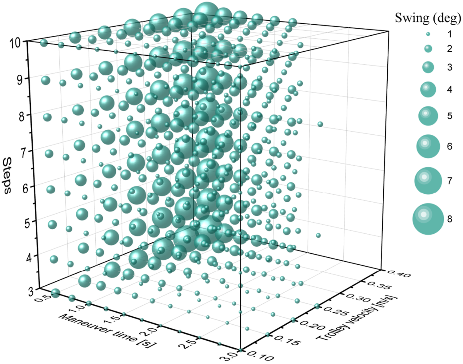
In the absence of swing constraints, three key points were made: (1) Effect of velocity: for a fixed maneuver time, the swing increases with increasing maximum velocity. This is because rapid acceleration to higher velocities results in larger acceleration inputs, thereby exciting larger swings. (2) Effect of maneuver time: for a fixed velocity, increasing the maneuver time reduces the swing, as longer maneuvers distribute acceleration over time and lower the excitation. (3) Effect of input steps: the number of input steps has little influence on the maximum swing. Without swing constraints, optimization primarily enforces the terminal state rather than the transient swing. Increasing the number of steps improves the degrees of freedom and terminal accuracy but does not significantly reduce peak swing.
Considering both operational efficiency and command effort, a maneuver time of 1.5 s and a maximum trolley velocity of 0.3 m/s were selected, together with a moderate number of input steps to balance performance and computational complexity. Simulation and experimental studies were then conducted for Cases 1–3 in Table 1. For benchmarking, the results are compared with the classical ZV and ZVD input shapers because they represent widely used open-loop command-shaping baselines under the same information structure. In addition, ZV and ZVD provide a clear reference for interpreting how constraint embedding and terminal-state enforcement affect the acceleration/velocity profiles and the resulting sway response. The comparative outcomes are reported in Figures.4–6. The results of simulation and experiment for case 1. (a) trolley acceleration; (b) trolley velocity; (c) payload swing; (d) trolley displacement. The results of simulation for case 2. (a) trolley acceleration; (b) trolley velocity; (c) payload swing; (d) trolley displacement. The results of simulation and experiment for case 3. (a) trolley acceleration; (b) trolley velocity; (c) payload swing; (d) trolley displacement.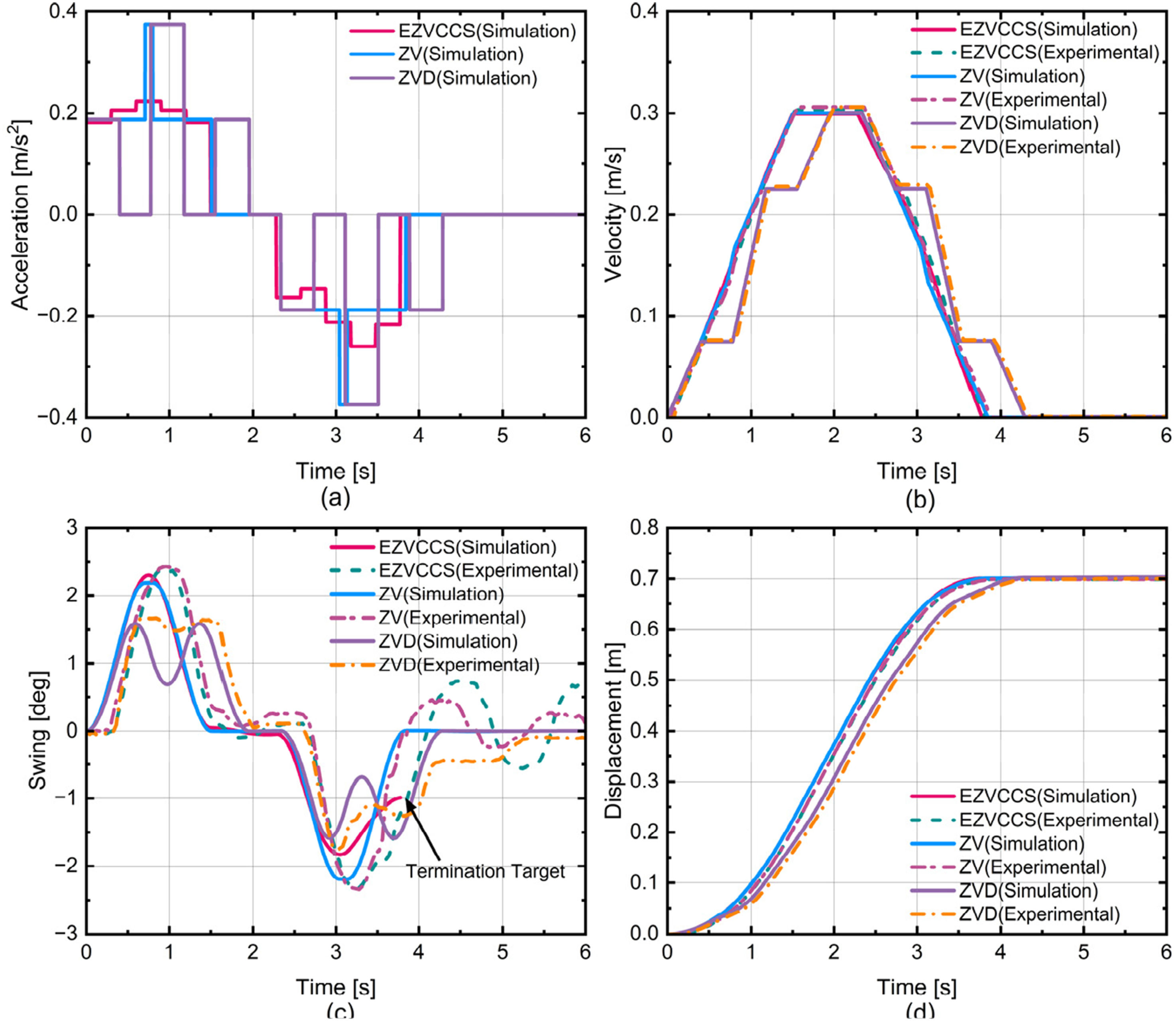
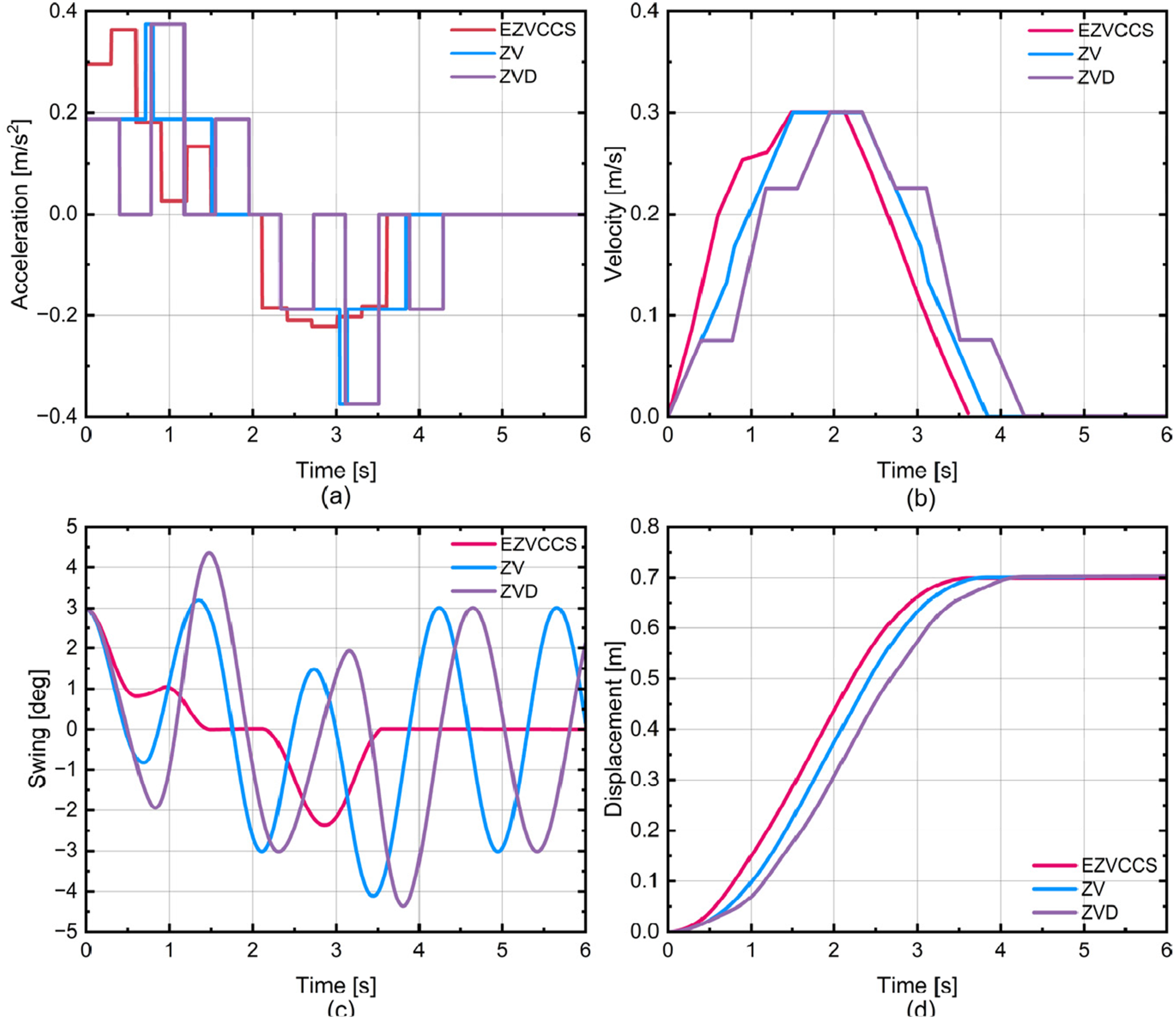
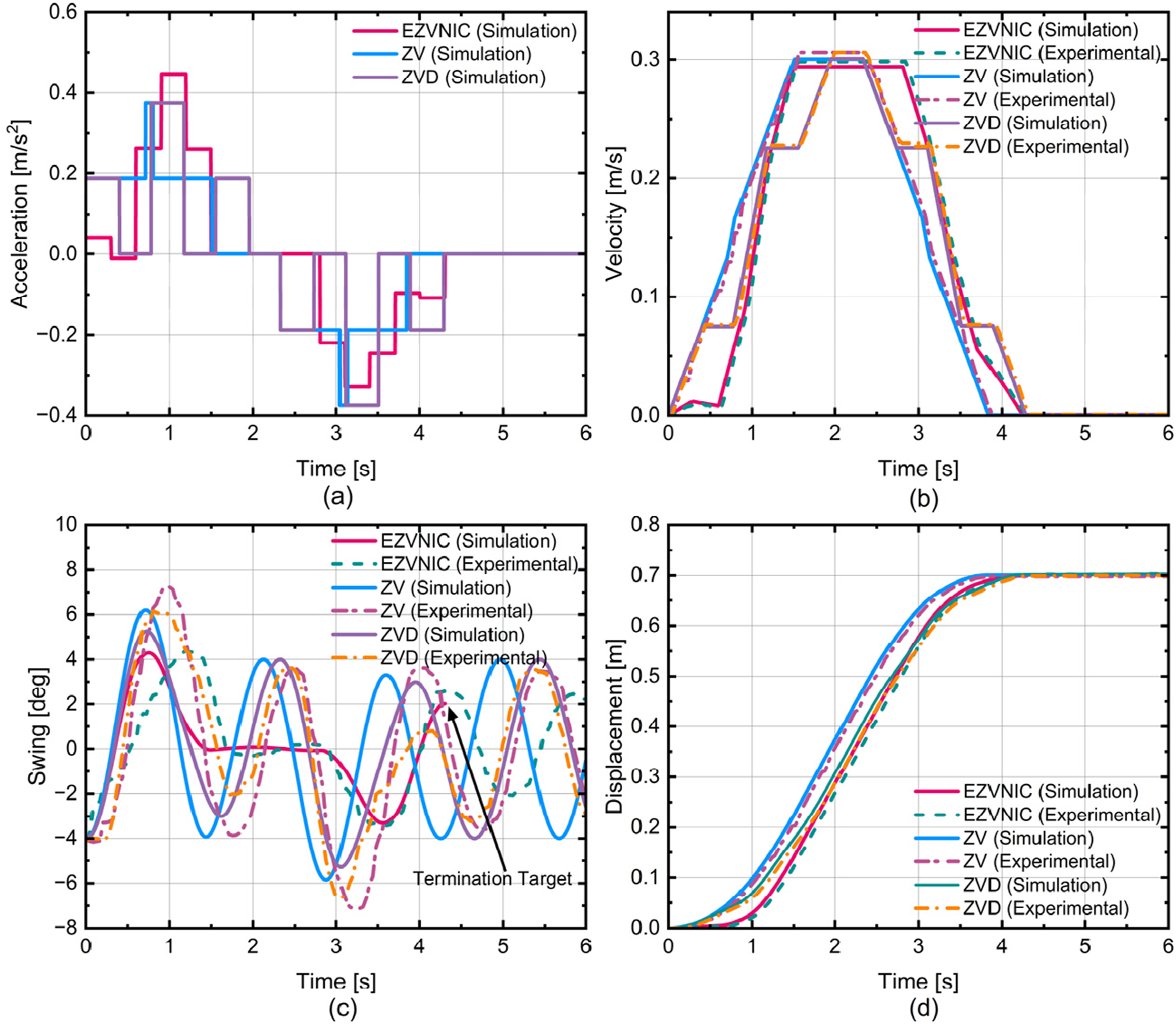
Figure 4 compares the swing suppression performance of the proposed method against the ZV and ZVD methods in the absence of initial swing. As shown in Figure 4(a), the method proposed in this paper requires lower acceleration input. The maximum trolley velocity reaches 0.3 m/s, as illustrated in Figure 4(b), where the velocity profiles of the proposed method and the ZV method are nearly identical. Because ZV and ZVD are designed to reduce residual vibration without explicitly enforcing terminal-state constraints, both methods keep the swing within a relatively small range but do not guarantee the desired final swing state. The ZVD shaper yields slightly smaller peak swing than the proposed method, primarily due to its longer maneuver duration. However, even with this extended maneuver time, bimodal oscillations are still observed, as depicted in Figure 4(c). In contrast, the proposed method explicitly enforces. The terminal-state requirements and therefore achieves the desired final condition. All three methods reach the target position accurately, as shown in Figure 4(d).
Figure 5 demonstrates the effect of a positive initial swing. As reproducing this condition experimentally is challenging, only simulation results are reported. As shown in Figure 5(c), neither ZV nor ZVD attenuates the initial oscillation, leading to sustained swing throughout the maneuver. By comparison, the proposed method confines the swing to within 3 degrees relative to the initial amplitude and drives it to the prescribed terminal state. Throughout the maneuver, the trolley velocity remains within the 0.3 m/s limit (Figure 5(b)), and the target displacement is achieved with high accuracy (Figure 5(d)).
Case 3 considers a negative initial swing, for which both simulation and experimental results are provided. As shown in Figure 6(c), the ZV and ZVD shapers again fail to handle the nonzero initial condition, resulting in persistent oscillations. The proposed method, however, maintains the swing within a smaller range and satisfies the terminal-state requirements. The experimental response agrees well with the simulation, with small deviations attributable to unmodeled friction and mechanical backlash. These discrepancies remain within an acceptable range for the testbed.
4.2. Study with swing constraints
In safety or confined operating environments, explicit limits on the maximum swing angle must be enforced, which substantially increases the difficulty of the shaping problem. To examine how maneuver time, velocity limits, and input step number affect feasibility and performance under such constraints, we solved the optimization problem over a range of scenarios with the different initial state while imposing explicit swing limits. The maximum allowable swing was varied from 2 degrees to 7 degrees in 1-degree increments. Because the additional swing constraint reduces the feasible set, the step number was selected no smaller than 4, and values from 4 to 11 were evaluated. For a given maneuver time and velocity limit, feasible solutions may exist for multiple swing limits. When visualized in a three-dimensional parameter space, these solutions can overlap and obscure the effect of the swing constraint. To improve readability, a small step-offset was applied to overlapping data points in the plot. The resulting solution distribution is shown in Figure 7. The system of solutions for maximum swing with constraints.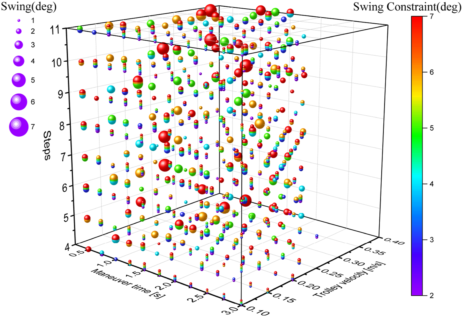
Figure 7 indicates that, once swing constraints are enforced, the input step number becomes a critical factor. For fixed maneuver time, speed limit, and swing bound, increasing the step number generally provides additional degrees of freedom that enable tighter sway regulation and can recover feasibility when no solution exists at lower step numbers. This behavior is expected: under strict constraints, a low-step command has limited decision variables and may be unable to satisfy multiple competing requirements simultaneously, whereas increasing the step number expands the feasible set and allows more precise shaping over the maneuver.
Nevertheless, larger step numbers increase computational complexity and do not guarantee improved performance in every case. As suggested by Figure 7, step numbers between five and nine provide a favorable balance between performance and complexity. To further illustrate this trade-off, Cases 4 and 5 were simulated using step numbers of five and 9, respectively.
Figure 8 presents Case 4 under a maximum speed of 0.3 m/s and a swing limit of 2 degrees. Because the initial swing is positive, the acceleration command initially counteracts the sway and drives the system toward the zero-swing state while respecting the constraint. Here we focus on the deceleration phase, where the swing is typically most sensitive to command design. For a maneuver time of 1s, both 5-step and 9-step designs confine the swing to within 2 degrees, showing comparable performance; thus, increasing the step number does not necessarily improve results in this scenario. Extending the maneuver time to 1.5s under the same constraints further reduces the swing. Overall, compared to an unconstrained design, enforcing swing limitations can improve safety by limiting peak swing, but the reduction in swing amplitude is not significant enough in these cases. The results of simulation for case 4. (a) trolley acceleration; (b) trolley velocity; (c) payload swing; (d) trolley displacement.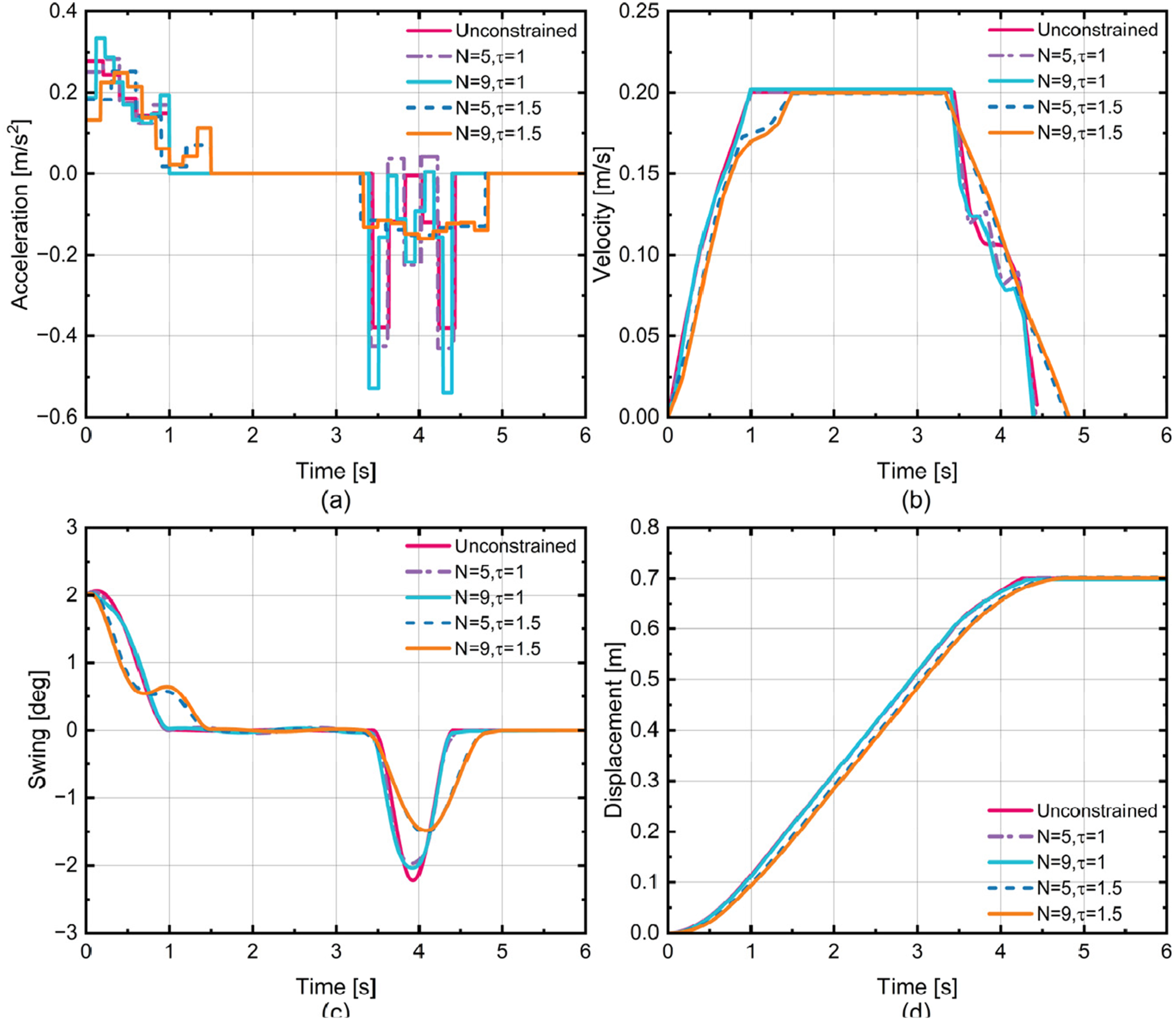
As illustrated in Figure 9, Case 5 evaluates a swing constraint of 3 degrees under maneuvering times of 1.5s, with maximum velocity limits of 0.2 m/s and 0.3 m/s. At 0.3 m/s with five steps, a double-peak swing response is observed. Increasing the step number to nine mitigates this phenomenon and confines the swing more effectively within the 3-degree limit. Under the velocity constraint of 0.2 m/s, the swing during deceleration is further reduced. This means that the minimum maximum velocity is beneficial in reducing swing, whereas a larger velocity constraint may be preferable when higher efficiency is prioritized and larger swing tolerance is acceptable. The results of simulation for case 5. (a) trolley acceleration. (b) trolley velocity. (c) payload swing; (d) trolley displacement.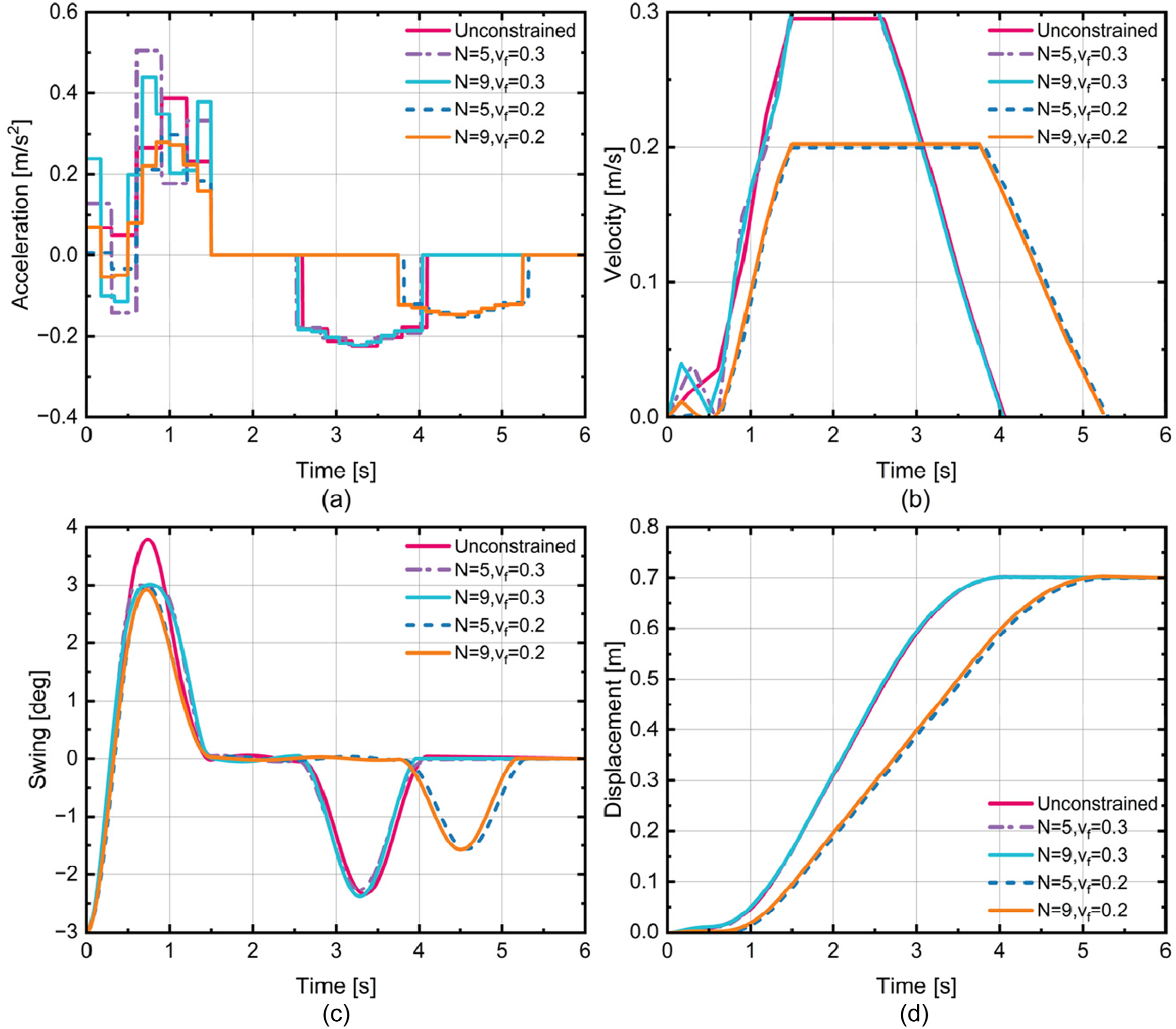
The study further reveals that, as the number of input steps N increases, the ZOH acceleration curve can approximate the continuous command with increasingly higher resolution. Therefore, as long as the reference command is sufficiently regular, when The results of simulation and experiment for case 6. (a) trolley acceleration; (b) trolley velocity; (c) payload swing; (d) trolley displacement.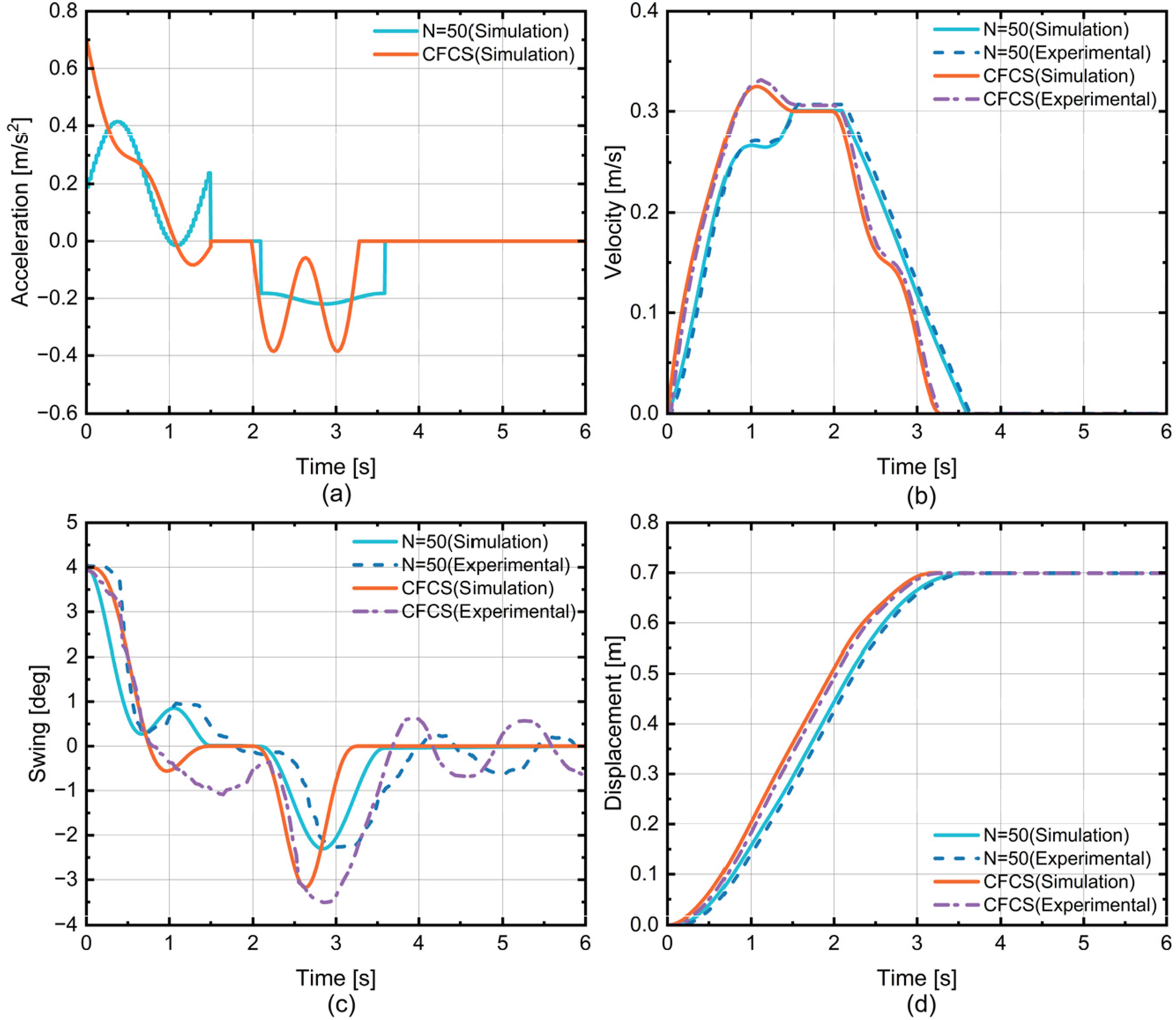
Case 7 further investigates swing suppression under constrained conditions. An input step number of 50 was selected, and both simulations and experiments were conducted with a maximum swing constraint of 2 degrees. As shown in Figure 11(a), both methods require comparable acceleration when the initial swing is small. However, Figure 11(c) indicates that the CFCS method produces a larger swing, whereas the proposed method successfully confines the swing within 2 degrees. Experimental results closely match the simulations, further validating the proposed approach. The results of simulation and experiment for case 7.v(a) trolley acceleration; (b) trolley velocity; (c) payload swing; (d) trolley displacement.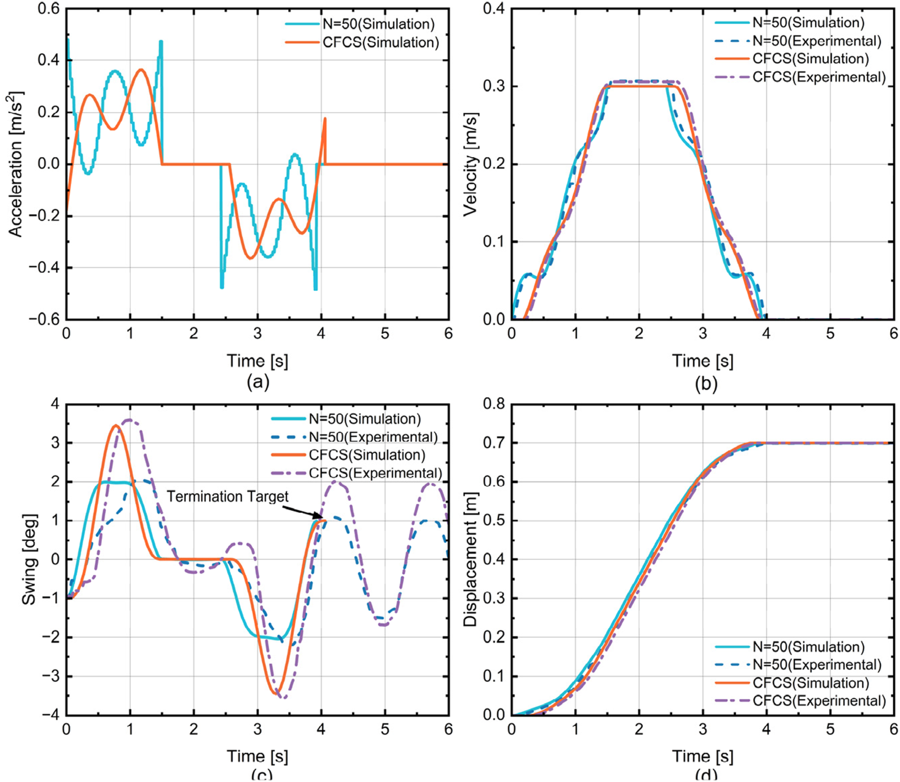
In summary, Figures 10 and 11 show that, as the step number increases, the acceleration profiles generated by the proposed method exhibit trends similar to those of the CFCS method. Despite this similarity, the proposed method provides more reliable constraint-compliant behavior and achieves smaller sway responses in the tested cases, particularly under explicit swing and velocity limits. Based on the simulation and experimental results, choosing a moderate step number (typically 5-9). Offers a practical compromise between sway reduction and implementation complexity. When stricter sway limits are required, increasing the step number can enlarge the feasible design space and further improve constraint satisfaction, although the resulting increase in computational cost should be taken into account in practical applications.
It is important to note that the remaining discrepancies between simulations and experiments are mainly attributed to unmodeled effects such as trolley friction, mechanical backlash, actuator bandwidth limits, and measurement noise. Since the EZVCCS method is a feedforward planning method based on an idealized dominant-mode model, these effects may introduce small deviations in peak swing and transient response; nevertheless, the experiments confirm consistent constraint satisfaction and terminal accuracy under the tested conditions.
5. Conclusion
This paper presents an EZVCCS framework for suppressing load sway in overhead cranes under arbitrary initial and prescribed terminal conditions. Extensive analyses under different constraint settings show that, with a small number of input steps, the proposed method maintains profiles comparable to classical ZV/ZVD shapers while providing improved mitigation of initial sway and guaranteeing satisfaction of terminal-state requirements within the imposed limits. As the input step number increases, the proposed method attains finer temporal resolution and can closely approximate the CFCS method; at the same time, the embedded swing constraints enable stricter regulation of the sway response. These results highlight the unified and scalable nature of the EZVCCS framework and its suitability for a broad range of point-to-point crane maneuvers.
Comprehensive simulations and experiments validate the effectiveness of the proposed approach. Nevertheless, this study focuses on feedforward trajectory planning for arbitrary initial and prescribed terminal conditions, and does not explicitly model unknown disturbances or parametric uncertainties. Future work will incorporate systematic sensitivity evaluations, disturbance modeling, and closed-loop compensation to further enhance robustness. In addition, while the present work adopts a single-pendulum crane model, extending the EZVCCS framework to multi-cable configurations and higher-order crane dynamics remains an important direction for future research.
Footnotes
Funding
The authors disclosed receipt of the following financial support for the research, authorship, and/or publication of this article: This work was supported by the National Key Research and Development Program of China (2018YFB1308301), the Transformation Program of Scientific & Technological Achievements of Jiangsu Province (BA2022057) and the Major Scientific and Technological Achievement Transformation Project of Suzhou City (SZCG202505).
Declaration of conflicting interests
The authors declared no potential conflicts of interest with respect to the research, authorship, and/or publication of this article.
Data Availability Statement
No data was used for the research described in the article.