
Abstract
The seawater hydraulic variable ballast system (SHVBS) is utilized for dynamically adjusting the buoyancy of submersibles, in which the balance valve acts as a critical component. However, vibration-induced dynamic instability of the valve severely restricts the high-precision operational performance of submersibles. To address the challenge of predicting the three-dimensional motion and collisions of the balance valve poppet and to investigate its vibration characteristics, this study employs a combined approach of three-dimensional CFD simulation and experimental analysis. Results demonstrate that the vibrational energy of the balance valve primarily originates from radial impacts between the poppet and the push rod. The impact frequency of the poppet increases with rising backpressure, and restricting the radial motion of the poppet can effectively improve the vibration characteristics of the balance valve under various working conditions. The findings of this study offer valuable insights for improving the vibration performance of similar types of valves.
Keywords
1. Introduction
As a critical component of SHVBS, the balance valve directly influences the outlet pressure of the seawater pump, the load on the motor, and the energy loss, all of which are determined by its dynamic behavior (Wang et al., 2022). During operation, unstable phenomena such as poppet self-excited oscillation, cavitation, and pressure fluctuations from seawater pumps frequently occur, which can deteriorate the working environment of submersibles (Wu et al., 2017). Vibration in the balance valve remains a key challenge in SHVBS that requires resolution. As early as 1973, Green (1973) identified several factors contributing to valve instability: interactions between the poppet and other components, transition from laminar to turbulent flow during opening and closing, negative restoring force, hysteresis in fluid forces, and fluctuating supply pressure. Chen et al. (2018) found that squeal noise in two-stage electro-hydraulic servovalves was caused by resonance between pressure pulsations from the power supply and the natural frequency of the armature assembly. Yi et al. (2016) demonstrated that squeal noise in poppet valves results from resonance between the acoustic natural frequency of the valve chamber and the excitation frequency induced by shear layer instability. Hős et al. (2014, 2015) combined a gas dynamics model with a single-degree-of-freedom structural model to explain flutter instability in pressure relief valves. Bazsó and Hős (2013) observed that in spring-loaded valves, the vibration frequency of the valve remains constant across a wide range of flow rates and set pressures, consistently matching the eigenfrequency of the outlet pipeline. In summary, the vibration frequency exhibited by valves during operation is generally associated with multiple excitation mechanisms, including the self-excited oscillation of the poppet, vortex shedding, system pressure pulsations, natural structural frequencies of the valve, acoustic resonance of the valve chamber, and eigenfrequency of the outlet pipeline.
The vibration mechanisms within spring-loaded valves, particularly the axial vibration behavior of the poppet, have been extensively studied in the academic community. EI Bouzidi et al. (2018a, 2018b) investigated the effects of valve spring stiffness, pipeline length, and initial spring compression on the stability of spring-loaded valves. Subsequently, an analytical framework was proposed to describe the fluid–acoustic–structure coupling in spring-loaded valves operating under subcritical conditions, thereby avoiding choking phenomena at the contraction section. Min et al. (2014, 2020) examined the axial vibration of a plunger valve using fluid–structure interaction simulations, and later employed visualization experiments to study the types of unstable vibration and the flow-field characteristics near the valve orifice, identifying the driving factors behind unstable vibrations. Liu et al. (2026) combined a CFD model with experimental methods to reveal the influence of inlet pressure, outlet pressure, and spring preload on the vibration characteristics of a conical valve. Keszthelyi et al. (2025) simulated a safety valve connected to a discharge pipeline via one-dimensional modeling and demonstrated the effect of increasing the length of the outlet pipeline. Bazsó (2016) developed a mathematical model of a pipeline–valve system to investigate the nonlinear dynamics of valve systems and proposed a design methodology to prevent static instability in valves.
However, investigations focusing solely on the axial motion of the poppet are insufficient to fully elucidate the vibration mechanisms of the valve. It is essential to integrate the study of its radial motion for a comprehensive understanding. Maeda (1970a, 1970b) conducted in-depth research on the lateral stability of the valve body and derived expressions for the lateral forces acting on the poppet. Wei et al. (2022) developed a CFD model to simulate the lateral vibration of the valve disc in a cryogenic flap control valve, investigating various valve openings and pressure differential conditions to explore the vibration mechanisms of the valve disc. Ji et al. (2018) studied the dynamic characteristics of simultaneous axial and lateral vibrations in a poppet valve and discussed the interaction mechanisms between these two types of vibration. Liu et al. (2024) proposed a novel theoretical model for analyzing vibrational characteristics in both axial and lateral directions, predicting the displacement of the valve disc and the flow response of the valve. Li et al. (2025) investigated the nonlinear characteristics of the spatial vibration of a conical valve core, concluding that the intensity and chaotic nature of the vibration increase with the pressure differential. A spring-loaded valve typically comprises a poppet, a valve body, and a pre-compressed spring. A key structural distinction between the balance valve and the spring-loaded valve lies in the separation of the push rod from the poppet. In the balance valve, the poppet is not directly actuated by the spring, resulting in fewer kinematic constraints during operation and more complex dynamic behavior. Research on the vibration characteristics of balance valves remains relatively limited. Most existing studies on the three-dimensional motion of the poppet rely on high-speed imaging through transparent valve bodies made of polymethyl methacrylate (PMMA) to capture vibrational trajectories. Furthermore, numerical simulations of poppet motion have predominantly focused on one-dimensional analyses, considering either axial or radial displacement in isolation, while neglecting the coupling effects between axial and radial motions as well as the collisions occurring during operation. Therefore, to more accurately represent the actual operating state of the poppet and to reveal the coupling mechanisms between its axial and radial motions as well as collision effects, it is essential to develop a three-dimensional coupled model that comprehensively accounts for multi-degree-of-freedom motion and collisions.
Only by understanding the vibration mechanism of the poppet can theoretically support and experimental basis be provided for the further optimization design and fault diagnosis of the balance valve. While structural parameters such as the geometric asymmetry of the valve outlet are fundamental causes of instability, backpressure serves as the primary operational variable in SHVBS due to continuous changes in diving depth. This operational factor directly governs the rate of change of fluid momentum, which dominates the self-excited vibration characteristics under working conditions. Therefore this study employed a three-dimensional CFD model to investigate the motion state of the poppet, combined with experimental approaches to identify the primary source of vibration in the balance valve and examine the influence of backpressure on its vibration characteristics. By measuring the vibration frequency of the poppet under different backpressure conditions and validating the simulated impact frequency and motion patterns through controlled experiments, the accuracy of the simulation model was effectively demonstrated. Furthermore, it was demonstrated that restricting the radial motion of the flap serves as an effective strategy for vibration suppression.
2. Working principle of balance valve
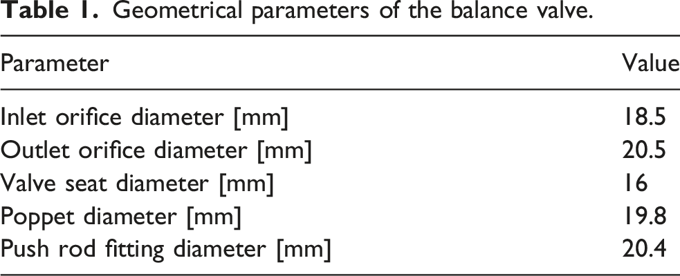
The balancing valve consists of a poppet, push rod, valve seat, valve body, plug, spring, and other components. To ensure self-centering of the poppet and reduce machining accuracy requirements, the poppet and push rod are designed as two separate parts. The valve body is made of stainless steel (316L), the push rod is made of polyetheretherketone (PEEK), the ball is made of ceramic (Si3N4), and the valve seat is made of stainless steel (316L) and polyamide (PA66). When the SHVBS is in drainage mode, the pressure in the balance cavity is essentially the same as the pressure in the water tank, and the outlet of the balancing valve is subjected to ambient seawater pressure. Under these conditions, the balancing valve functions similarly to a check valve. When the SHVBS is in injection mode, the pressure in the balance cavity is essentially the same as the ambient seawater pressure, and the outlet of the balancing valve is subjected to the water tank pressure. In this case, the balancing valve effectively prevents seawater from entering the water tank directly through the seawater pump, thereby avoiding loss of control of the submersible. In this study, the balance valve was experimentally investigated in the discharge mode, and its working principle is illustrated in Figure 1. Due to the low spring stiffness, when the outlet pressure of the balancing valve Working principle of the balance valve in discharge mode. Geometrical parameters of the balance valve.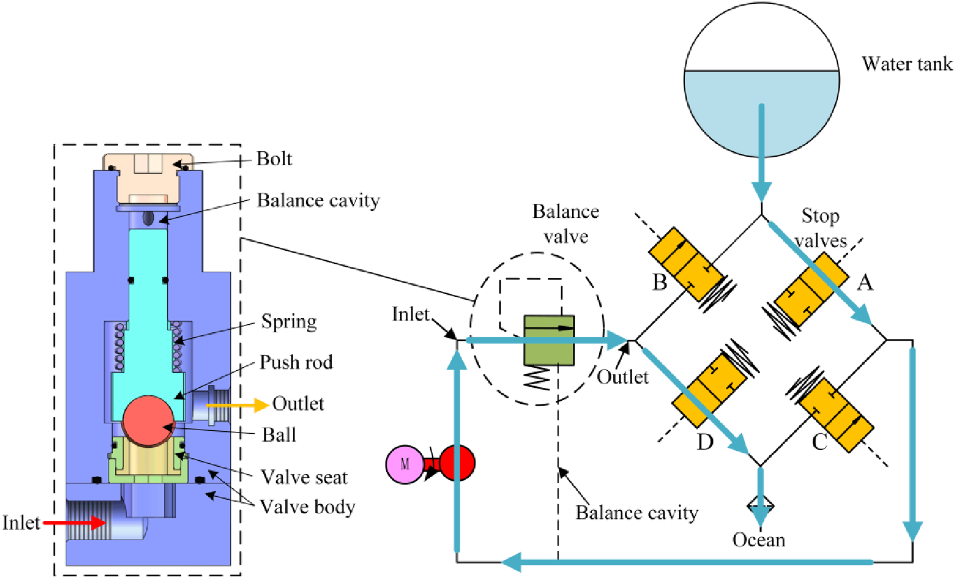
The three-dimensional motion of the poppet comprises axial motion and radial motion. The axial motion is governed by the following differential equation: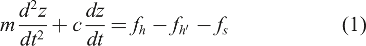
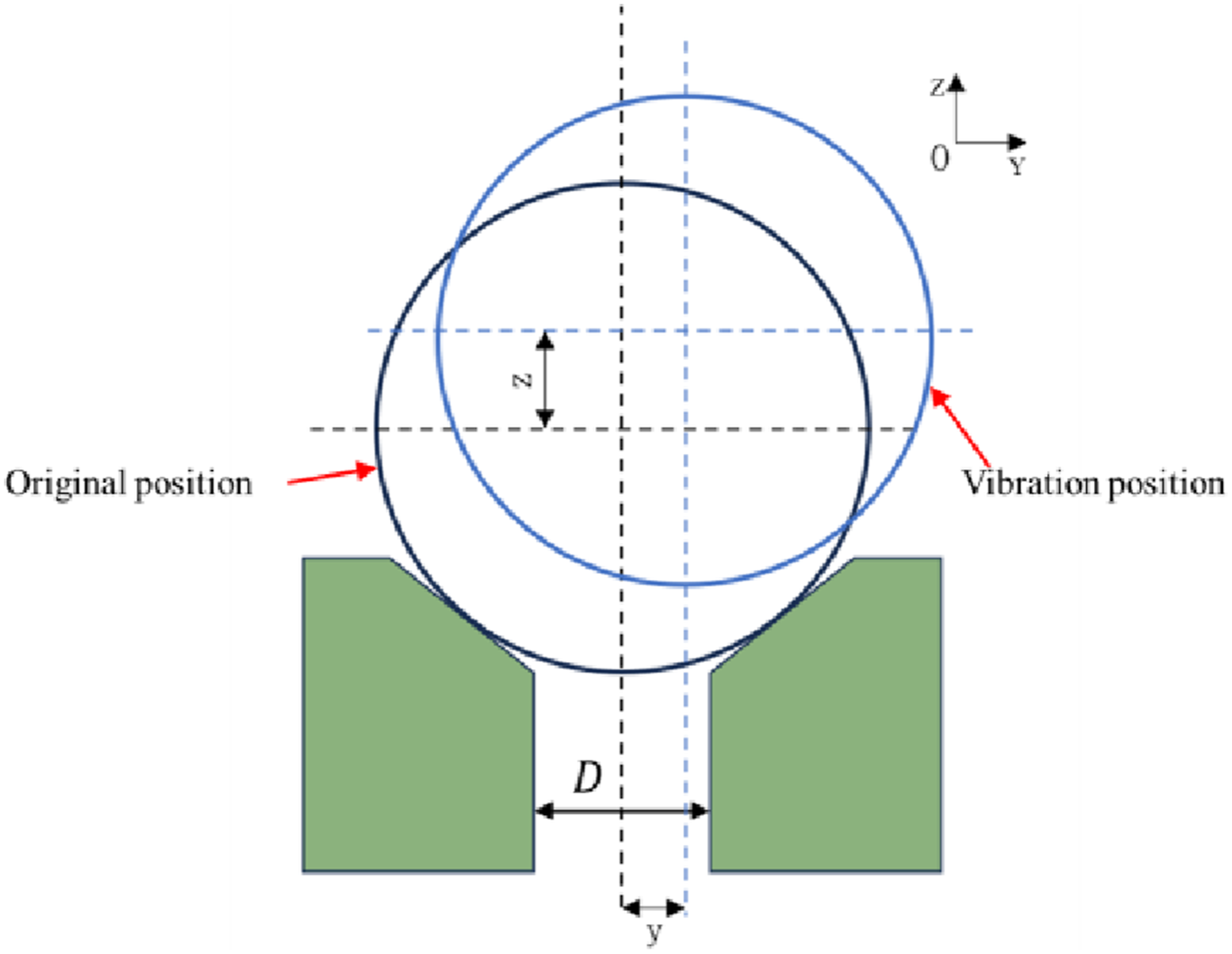
In the radial direction, the poppet is subjected to two main forces: a positive damping force generated by fluid squeeze between the poppet and valve seat, and a negative damping force resulting from the rate of change of fluid momentum. A schematic diagram of its motion is illustrated in Figure 2. The radial motion can be described by the following equation: Schematic diagram of poppet movement.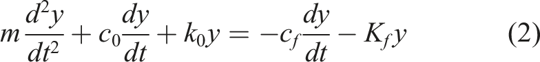
3. Simulation analysis
3.1. Flow-field simulation theory
A full 3D deformable mesh model of the valve was established in ANSYS-FLUENT, simulating the transient flow of an incompressible, viscous, single-phase Newtonian fluid (water) governed by the unsteady RANS equations.
Continuity equation: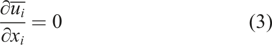
Momentum equation: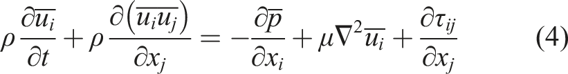
Where the Reynolds Stress Tensor in the momentum equation has been modeled using an Eddy Viscosity Model, according to: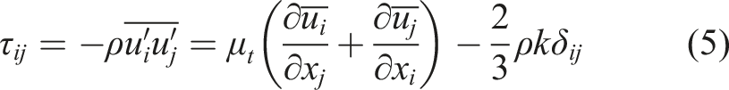
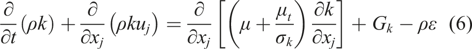
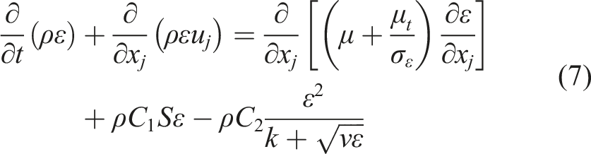
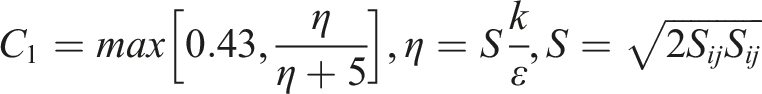
In the above equations, 
3.2. Computational mesh
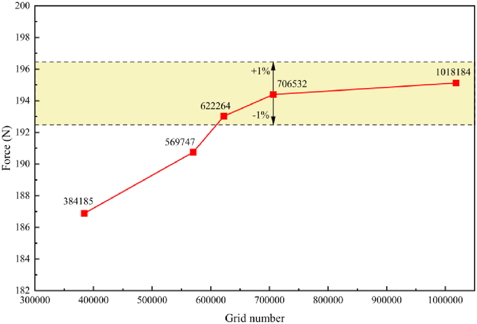
A three-dimensional flow-field model was developed in ANSYS and discretized using an unstructured mesh. To enhance computational accuracy, local mesh refinement was applied to the poppet, push rod, and valve seat. The inlet and outlet pipes were extended to lengths determined based on the diameters of both the inlet and outlet to minimize the influence of boundary conditions on the numerical solution. The resulting mesh is illustrated in Figure 3. Grid independence was verified with the initial poppet opening and a backpressure of 5 MPa as reference conditions, by examining the z-direction force on the poppet surface. Figure 4 shows the force values under different mesh sizes (ranging from 3,384,185 to 1,018,184 nodes). The results indicate that when the number of grid nodes exceeds 706,532, the relative change in the surface force is less than 1%. Therefore, a total of 706,532 nodes were selected for the final computational model. Meshing of the fluid domain. Mesh independence check for different grid numbers.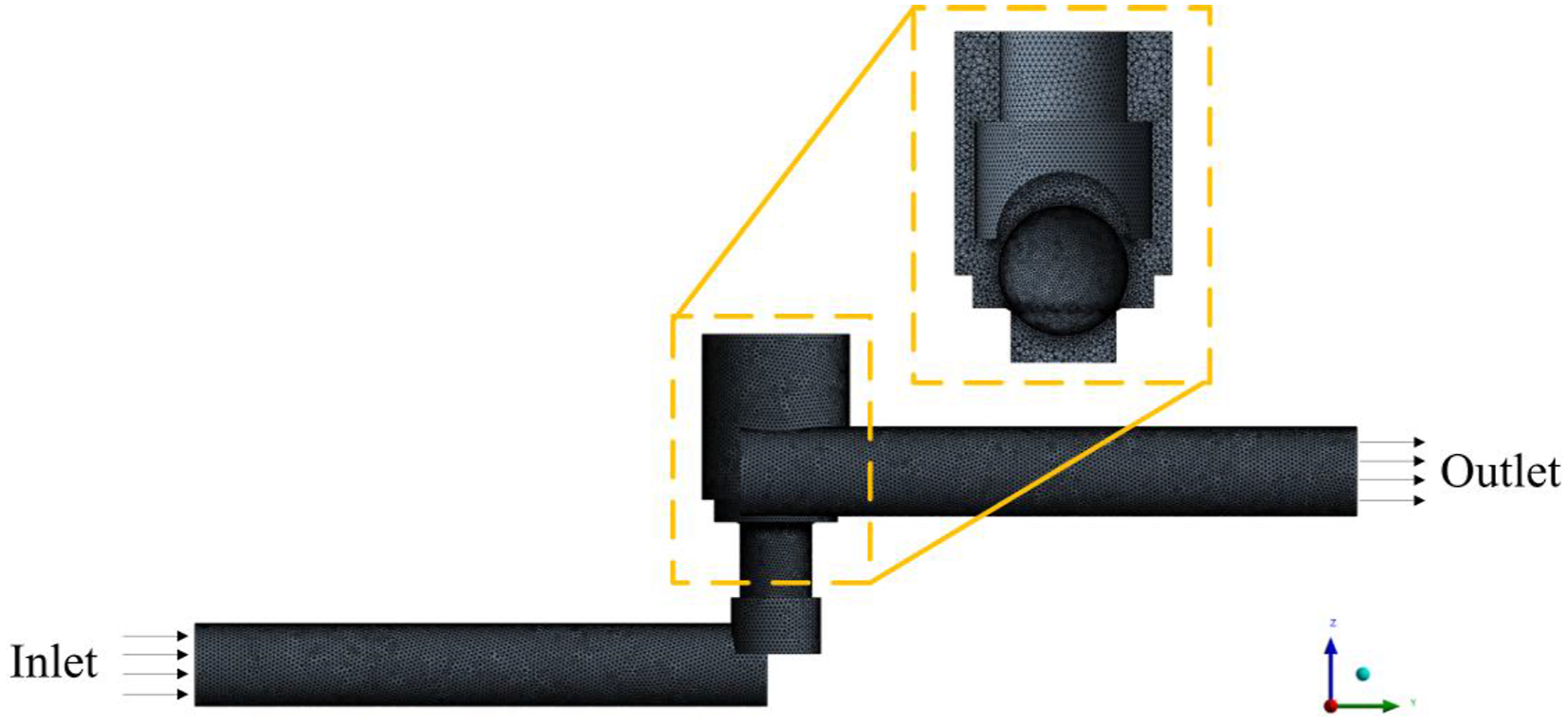
3.3. Collision settings
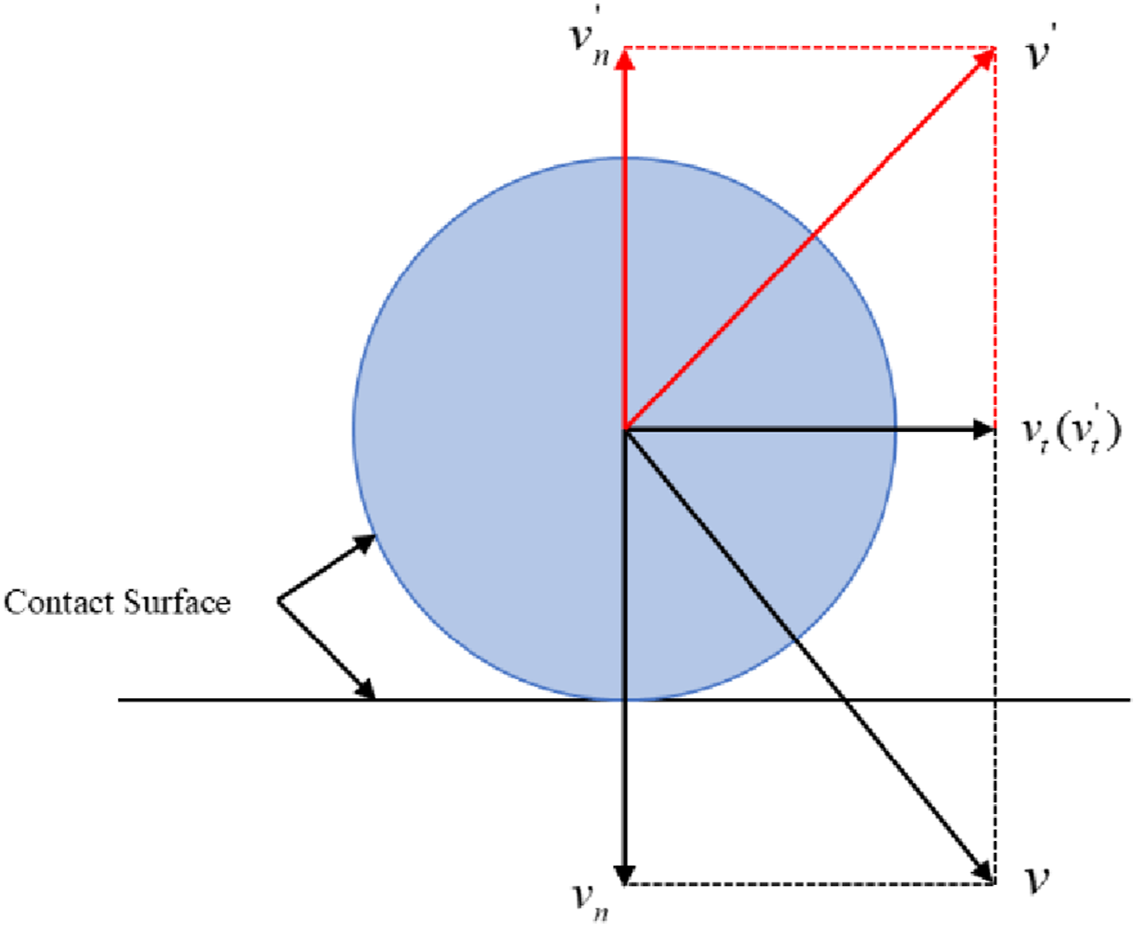
In the present simulation, the collision between the poppet and push rod is simplified as a specular reflection via a user-defined function (UDF). During impact, the velocity of the poppet is resolved into two components: one normal (perpendicular) and one tangential (parallel) to the contact surface. Under the assumption of negligible friction between the poppet and push rod, collision dynamics principles dictate that the normal velocity follows the restitution coefficient relation ( Schematic diagram of specular reflection impact.
The coefficient of restitution during normal contact/impact between an elastic sphere and an elastic–fully plastic substrate primarily depends on the initial relative contact velocity and material properties, as given by the following expression (Ma et al., 2024):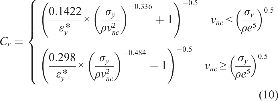
3.4. Solution strategy
The push rod surface was defined as a stationary zone, while the poppet surface was set as a dynamic mesh zone with six degrees of freedom (6DOF) enabled. A user-defined function (UDF) was implemented to perform contact detection by continuously monitoring the distance between the poppet and the valve seat or push rod at the end of each time step. When this distance is less than or equal to the preset value, a collision is considered to have occurred. The restitution coefficient is then calculated based on the component of the poppet velocity along the contact normal, which is subsequently used to determine the rebound velocity of the poppet. The boundary conditions at the poppet inlet and outlet were specified as velocity inlet and pressure outlet, respectively, with the inlet flow velocity set to Simulation workflow.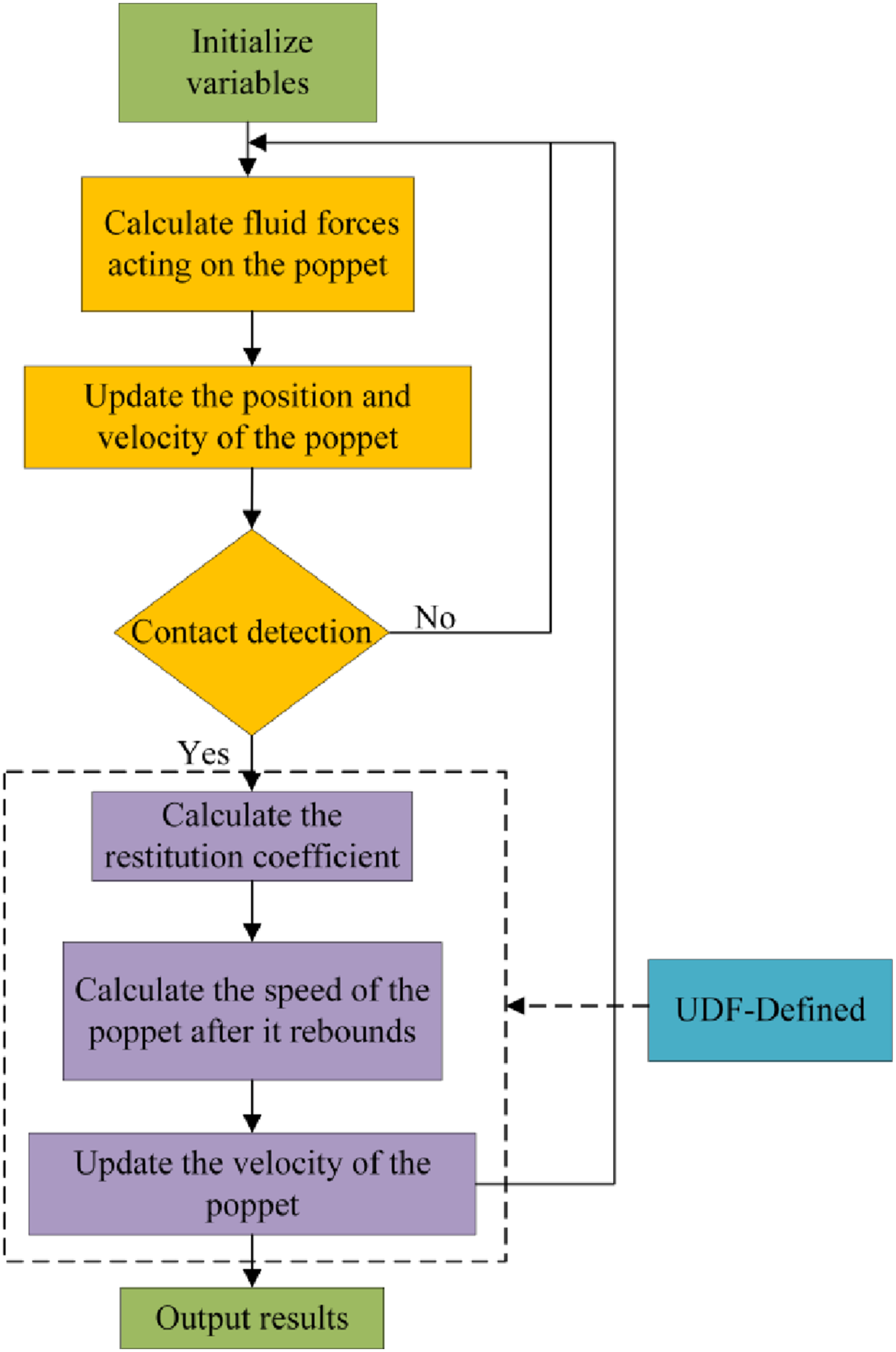
3.5. Simulation results
To identify the flow mechanisms responsible for radial instability in the balance valve, we analyzed the pressure distribution and streamline patterns under a backpressure of 5 MPa, as shown in Figure 7. The analysis reveals the formation of a wall-directed vortex near the push rod during the valve opening process. This vortex structure, combined with the geometric asymmetry of the valve outlet, generates an unbalanced hydraulic force that drives the poppet to move preferentially along the outlet direction, thereby inducing radial instability. These results demonstrate that the radial instability of the poppet originates fundamentally from the structural configuration of the valve body. Initial opening flow patterns and pressure distribution in the balance valve.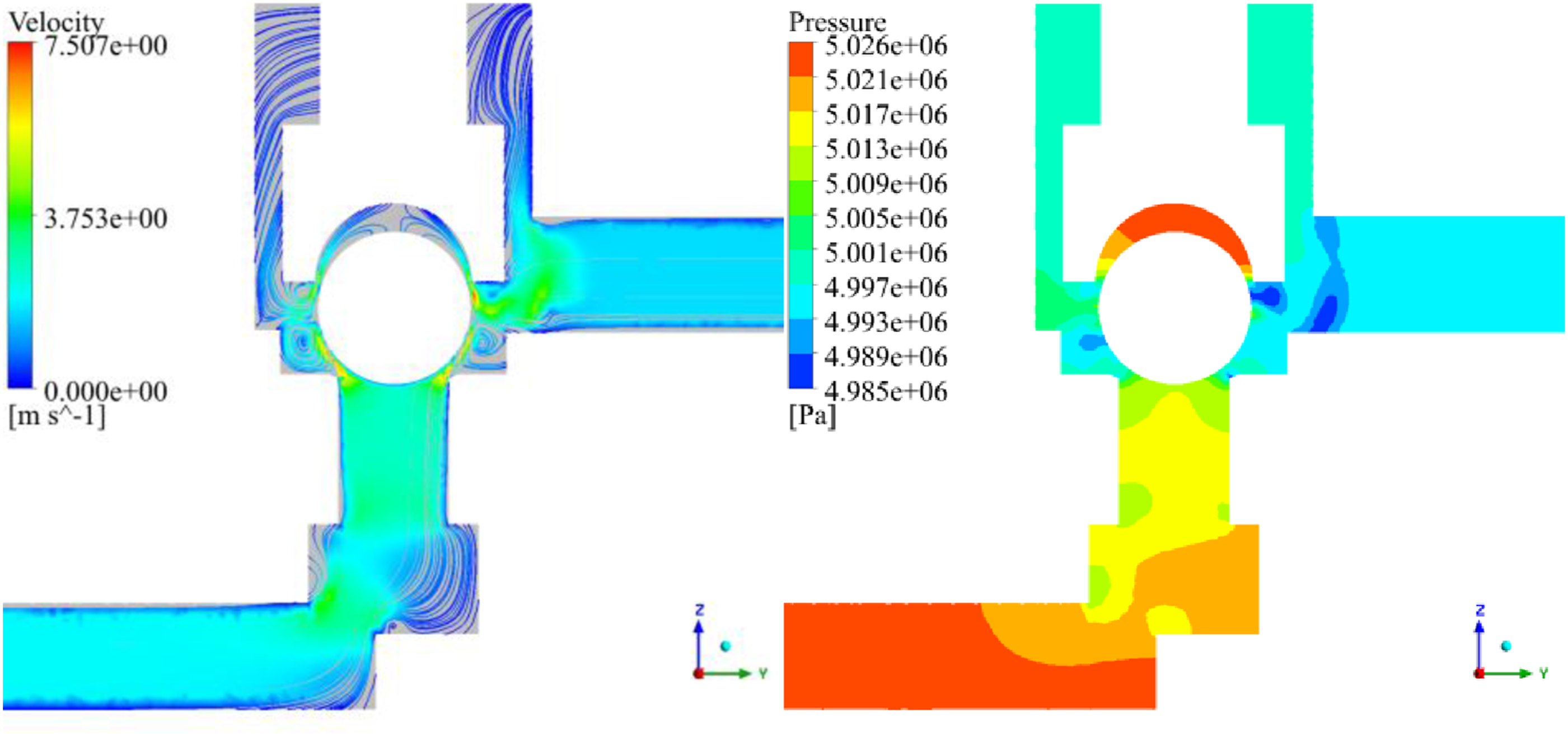
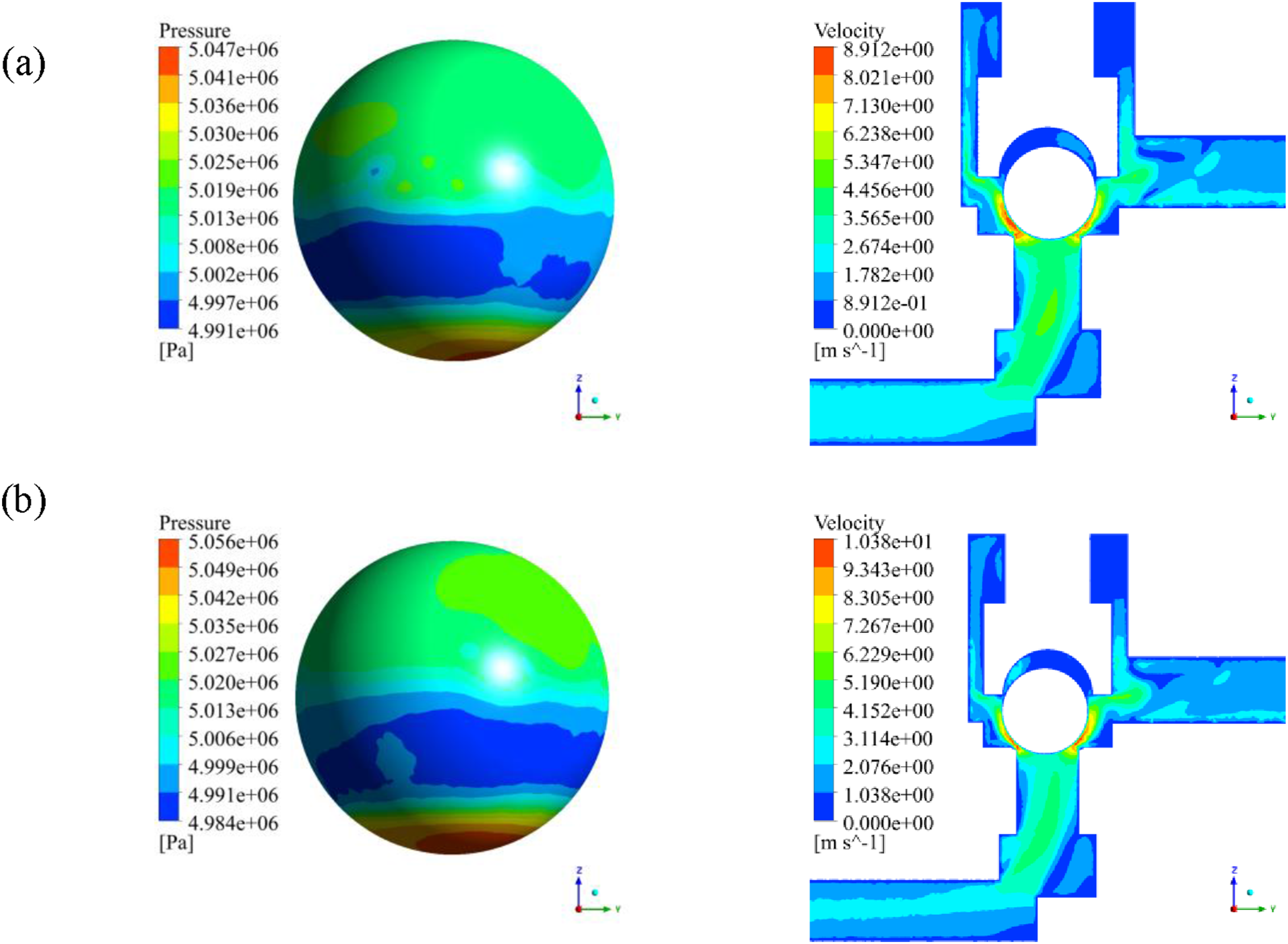
The motion characteristics of the poppet were evaluated by tracking its center-of-mass coordinates during Spatial trajectory of the poppet center of mass. Pressure distribution and flow-field streamlines on the poppet surface during collision: (a)T = 0.0889 s; (b) T = 0.0940 s.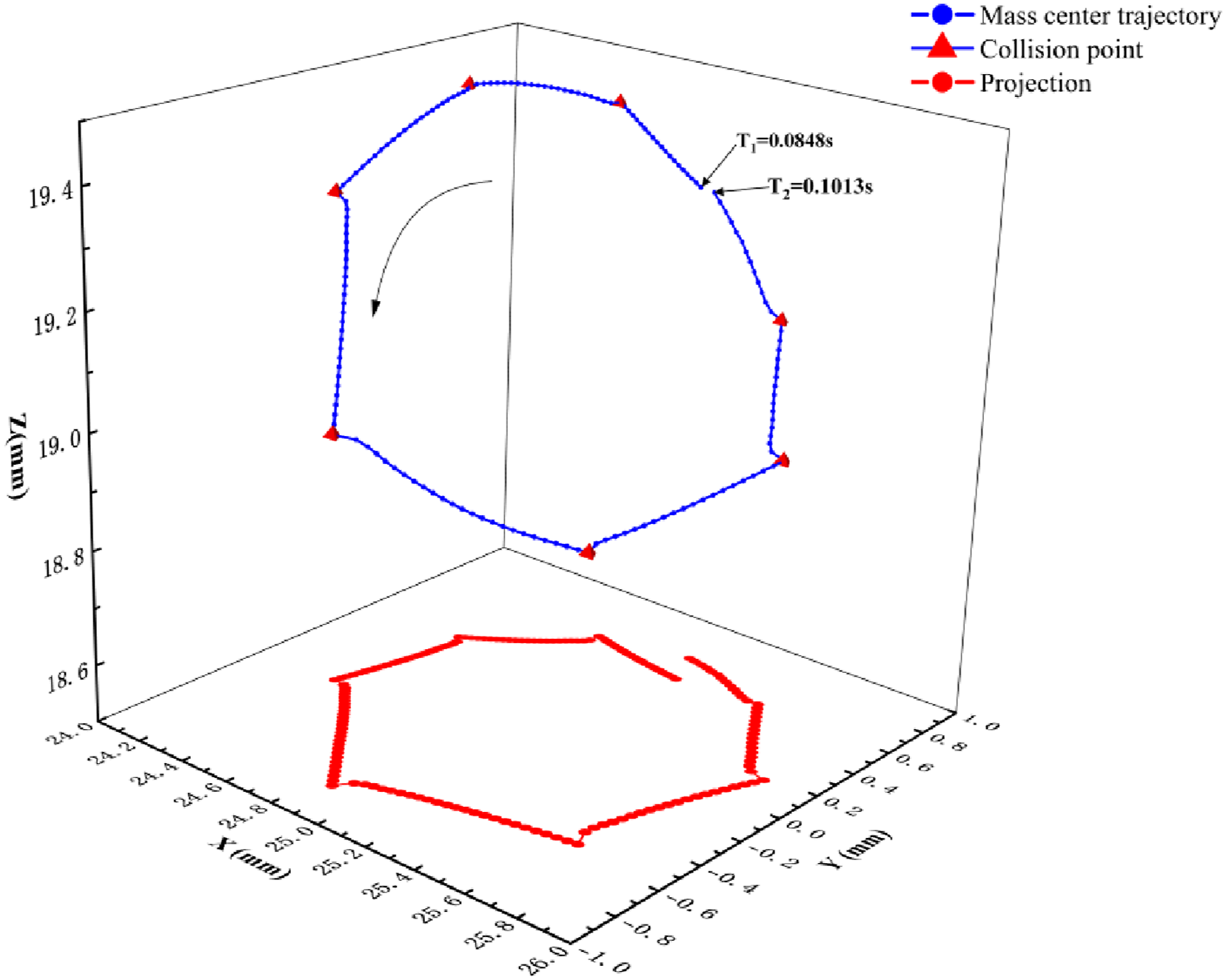
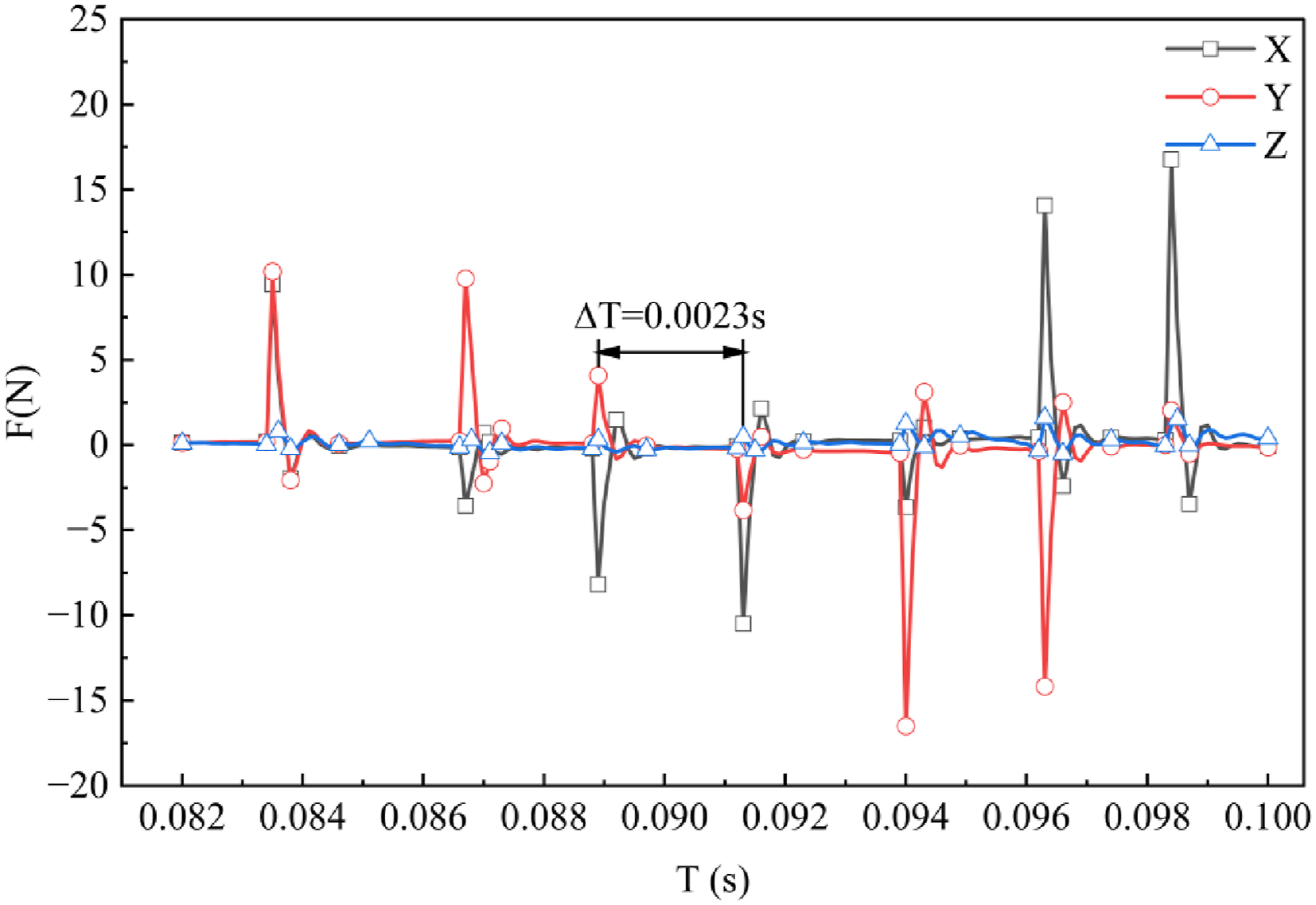
To characterize the hydrodynamic forces exerted on the balance valve poppet during impact, the synchronized variations along all three spatial directions (x, y, z) are plotted in Figure 10. The results indicate that the surface forces acting on the balance valve poppet exhibit distinct periodic variations over time along all three spatial directions (x, y, z), with fully synchronized fluctuation periods observed across these directions. The variation of the axial hydrodynamic force (z-direction) is significantly smoother than that of the radial components, as the axial force is primarily governed by the global pressure drop across the valve and is subject to an integral smoothing effect. Conversely, the radial forces (x and y directions) respond sharply to local gap variations and intense pressure gradients at the limit positions, resulting in distinct impulsive peaks. The surface forces continuously change as the gap between the poppet and the valve seat varies. This gap reaches its minimum when the poppet collides with the push rod. Therefore, the time instances corresponding to the extreme values of the surface forces in Figure 10 can be identified as the collision moments between the poppet and the push rod. The impact frequency between the poppet and the push rod matches the variation frequency of the surface forces. The simulation results indicate that the impact frequency between the poppet and the push rod increases significantly with rising backpressure in the balance valve. Under a backpressure of 5 MPa in the balance valve, the time interval between successive impacts is approximately Hydraulic pressure distribution on the poppet surface.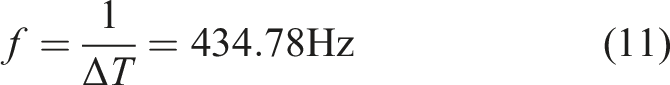
4. Vibration characterization experiments
4.1. Experimental setup
Figure 11 presents a schematic overview of the vibration testing system for the balance valve, designed to investigate its vibrational characteristics under operational conditions. The test setup comprises a radial piston pump, the test valve, a throttle valve, and other auxiliary components. The electric motor operates at 500 r/min, with a pump displacement of 62 mL/min. The throttle valve is employed to simulate the outlet load of the balance valve. For the acquisition of vibration signals, a BK4535 B accelerometer (frequency range: 10 Hz–10 kHz) was fixed to the balance valve body. The sensor acquires tri-axial vibration data (x, y, z), which are transmitted via a data acquisition card to a computer for processing. The overall vibration level was determined based on one-third octave band analysis. Schematic of the vibration testing setup for the balance valve.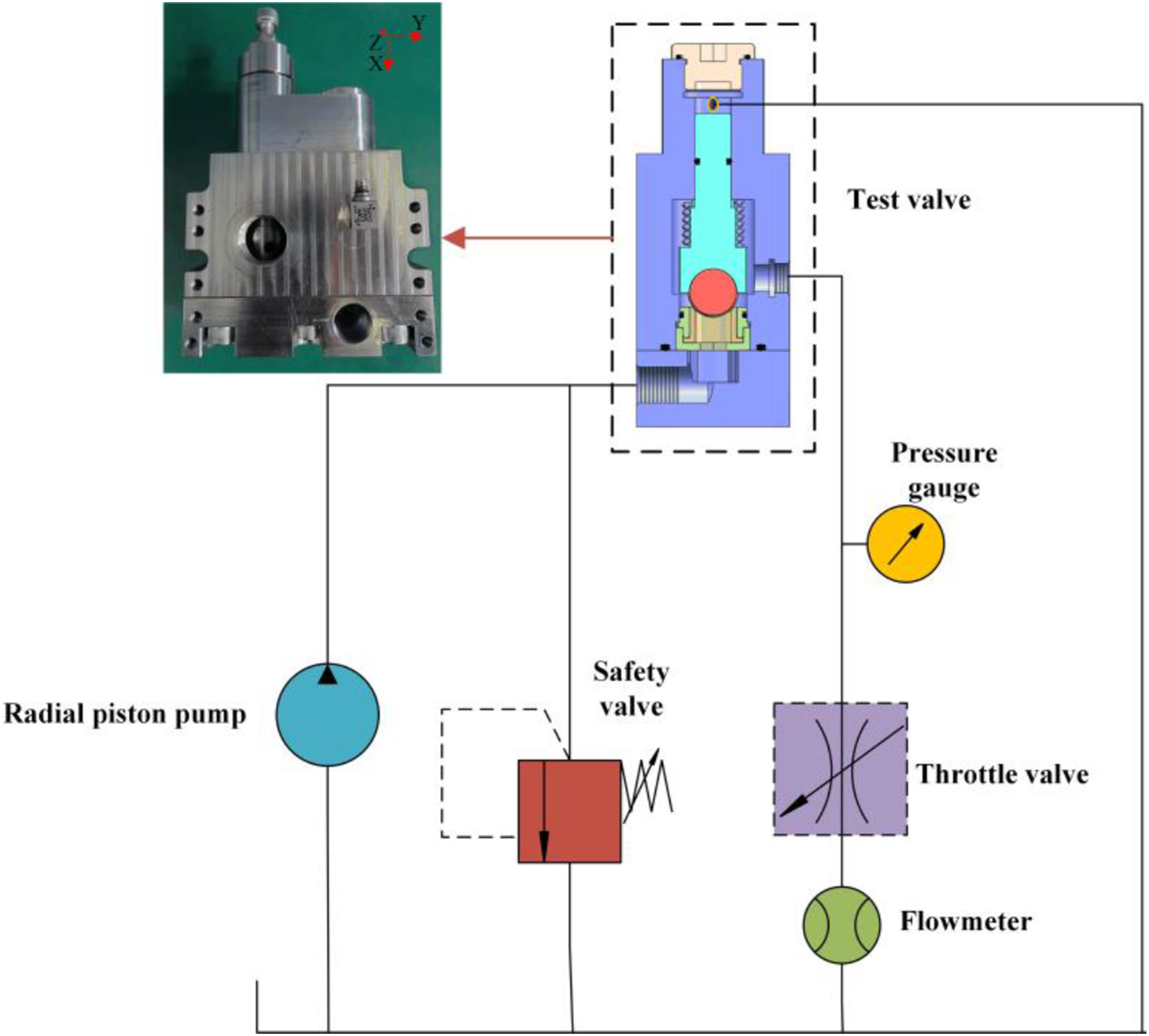
4.2. Experimental result
The vibration spectra of the balance valve in the x-, y-, and z-directions were obtained through accelerometer measurements under 5 MPa backpressure, as presented in Figure 12. The peak vibration frequency is observed at 424.4 Hz, which deviates by only 2.4% from the simulated impact frequency, and remains consistent across all three measurement directions. The substantial amplitude observed in the experimental z-direction aligns with the simulated radial hydrodynamic excitation (y-direction) due to the orientation of the accelerometer during measurement. This consistency between the simulated excitation source and the experimental structural response further validates the accuracy of the dynamic model. During operation of the balance valve, the low-frequency components of the vibration spectrum are predominantly governed by the flow pulsation frequency generated by the piston pump. The mid-frequency characteristics are mainly composed of the impact frequency between the poppet and push rod along with their harmonic components, while the high-frequency energy is primarily attributed to flow disturbances induced by cavitation effects. Due to the rigid constraint of the push rod, it forms a high-stiffness subsystem together with the valve body. In this dynamic model, the impact between the poppet and this subsystem is characterized by a high coefficient of restitution. The spring fails to effectively store energy, resulting in the peak impact energy being transmitted efficiently in the form of stress waves to the valve structure, with relatively limited energy dissipation. Thus, the dominant frequency component in the vibration spectrum corresponds to the impact frequency between the poppet and the push rod, which aligns well with the poppet motion excitation and the stiffness characteristics of the system. Vibration acceleration spectrum of the balance valve at 5 MPa back pressure.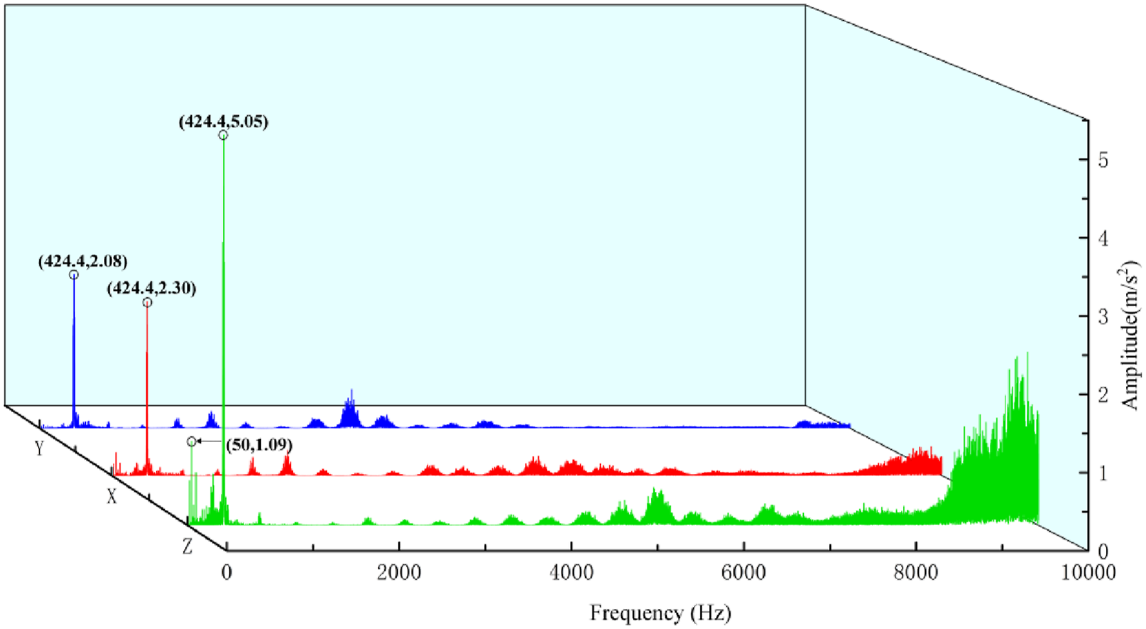
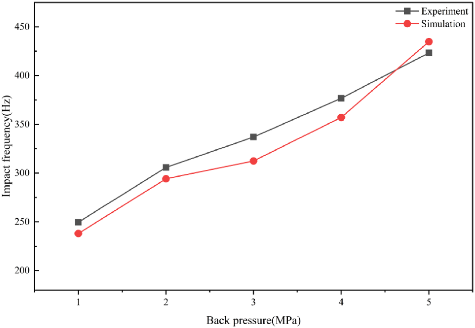
To investigate the vibration characteristics of the balance valve under varying backpressures, the relationship between the peak vibration frequency and backpressure was analyzed by comparing experimental and simulation results, as shown in Figure 13. As the backpressure was gradually increased from 1 MPa to 5 MPa by adjusting the throttle valve, the peak vibration frequency rose from 249.7 Hz to 424.4 Hz, closely matching the impact frequencies predicted by the simulation throughout the pressure variation. This close correspondence demonstrates the model’s capability for accurate prediction of the dominant vibration characteristics. The pressure pulsation frequency of the piston pump is Effect of backpressure on balance valve vibration.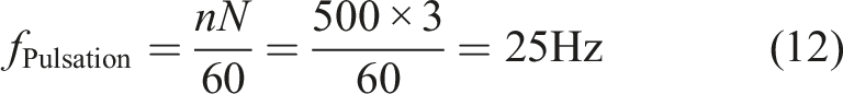
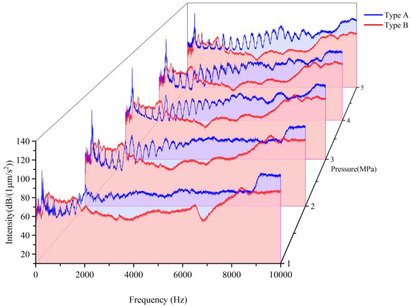
Analysis of the poppet trajectory in Figure 8 suggests that restricting its radial motion may be considered as a viable strategy for vibration suppression. Experimental measurements were conducted to compare the vibration characteristics of two balance valve configurations, Type A and Type B, under a backpressure of 5 MPa, as shown in Figure 14. Structurally, the Type B balance valve push rod provides a smaller contact distance with the poppet at identical lift positions compared to the Type A design ( Push rods for the two balance valve configurations: (a) Type A balance valve; (b) Type B balance valve. Acceleration signal spectra of the two balance valves under 5 MPa backpressure.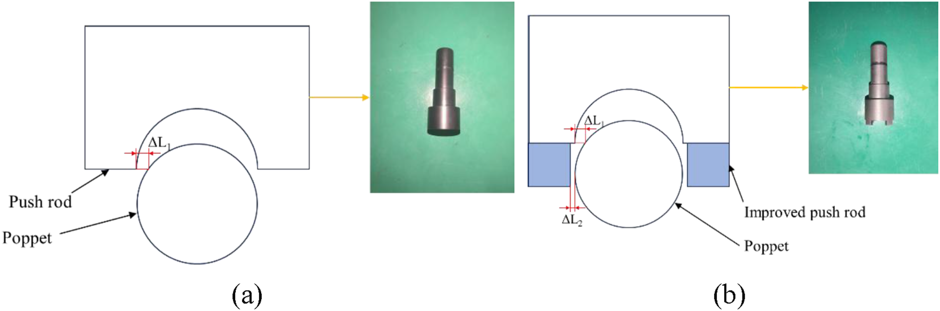
5. Conclusion
This study establishes a three-dimensional CFD model to simulate the three-dimensional motion of the poppet in a balance valve, aiming to investigate the causes of vibration and noise during operation. The validity of the simulation was verified experimentally, and the vibration characteristics of the balance valve were analyzed. The main conclusions are summarized as follows: (1) The vibration of the balance valve primarily originates from the self-excited oscillation of the poppet. During the opening process of the balance valve, flow passage asymmetry at the outlet leads to eccentric motion of the poppet. The resulting unbalanced surface forces induce radial oscillations, and the vibration energy is efficiently transmitted through the rigid push rod–valve body system to the valve structure, significantly influencing the overall system. (2) The peak vibration frequencies of the balance valve under various operating conditions closely match the simulated impact frequencies of the poppet. The consistency of the peak frequencies across the x-, y-, and z-directions also aligns with the simulated surface forces on the poppet, which validates the simulation accuracy to a certain extent. (3) Increasing the backpressure amplifies the oscillation amplitude of the poppet, leading to a significant rise in the peak vibration frequency. Restricting the radial motion of the poppet effectively reduces valve vibration, with the vibration intensity in the outlet direction being reduced by up to 19.95 dB under identical conditions. This finding provides a valuable strategy for vibration suppression in valves of similar types.
Footnotes
Funding
The authors disclosed receipt of the following financial support for the research, authorship, and/or publication of this article: This work was supported by the National Natural Science Foundation of China (No. 52235001) and the Natural Science Foundation of Hubei Province of China (2023AFA031). The authors wish to gratefully acknowledge these supports.
Declaration of conflicting interests
The authors declared no potential conflicts of interest with respect to the research, authorship, and/or publication of this article.