
Abstract
To improve the braking pressure tracking performance of the electro-hydraulic braking (EHB) system, this paper proposes a high-precision brake pressure control strategy. Considering the effects of nonlinear friction and external disturbances on pressure control, a master cylinder pressure dynamic model is established, and a hierarchical control architecture is constructed, consisting of an upper-level pressure servo loop and a lower-level motor current loop. An improved PINN–LuGre friction model is introduced to enhance the accuracy of nonlinear friction characterization, while an improved linear extended state observer (ILESO) is employed to estimate and compensate for external disturbances in real time. Based on this, the upper-level pressure servo loop adopts an improved super-twisting sliding mode control (ISTSMC) scheme to achieve robust pressure tracking, and the lower-level motor current loop achieves precise actuation based on feedforward decoupling. Hardware-in-the-loop (HiL) experimental results show that the proposed strategy improves pressure tracking accuracy under ramp and step conditions. For low- and high-frequency sinusoidal conditions, the RMS error is significantly reduced, validating its effectiveness.
Keywords
1. Introduction
With the rapid advancement of the automotive industry toward intelligent and energy-efficient technologies, modern vehicles place higher demands on the responsiveness and control precision of braking systems (Jiang et al., 2024; Sun et al., 2025). As a core component of brake-by-wire technology, the EHB system has emerged as a key development direction for intelligent vehicle braking systems due to their fast response, high controllability, and ease of integration with advanced driver assistance systems (ADAS). However, as the underlying execution layer of the EHB system, brake pressure control is susceptible to nonlinear friction and external disturbances, making achieving accurate tracking of the desired pressure under complex operating conditions a key technical challenge in current research (Liang et al., 2025).
Existing studies on brake pressure control for the EHB system have primarily employed proportional–integral–derivative (PID) control, fuzzy control, or their combinations. For example, Han W et al. (Han et al., 2023) proposed a pressure control method combining a PI observer with speed-feedback correction and adaptive friction compensation to improve brake pressure tracking performance. Compared with conventional actuator-based approaches, this strategy achieved more than a 10% improvement in tracking accuracy. Zhou ZG et al. (Zhou et al., 2022) considered the hysteresis characteristics of the EHB system, established a dynamic response model, and designed a dynamic fuzzy controller to regulate wheel cylinder pressure. The results showed that the steady-state pressure error under this strategy did not exceed 2.3%. In addition, Yang Y et al. (Yang et al., 2020) combined PID and fuzzy control to propose a novel hybrid pressure control method, achieving precise brake pressure regulation with performance superior to that of PID or fuzzy control alone. These approaches are relatively simple in structure and easy to implement in engineering practice. However, most of these studies rely on empirical rules or simplified models and typically neglect the effects of nonlinear friction and external disturbances when modeling EHB systems. In practice, nonlinear friction and external disturbances are ubiquitous and often cause steady-state pressure errors, particularly during rapid pressure transients, thereby limiting the braking performance of the EHB system under complex operating conditions.
To address the nonlinear friction effects and external disturbances in hydraulic systems, most studies have begun to focus on improving friction modeling and disturbance compensation methods (Han et al., 2019). Specifically (El-bakkouri et al., 2024), employed a position-dependent Coulomb–viscous friction model to characterize the system’s frictional characteristics Zhao et al. (2024) combined the LuGre friction model with a pressure control method, achieving higher control accuracy. Based on this, Cao et al. (2024) further introduced an improved active disturbance rejection control (IADRC) strategy to enable precise regulation of braking pressure. In addition, Ji et al. (2022) developed a novel asymmetric continuous friction model and combined it with an extended state observer (ESO) to effectively suppress the impact of nonlinear friction and external disturbances on brake pressure tracking performance. Although these methods improve system control performance, the classical friction models introduced are often sensitive to parameter variations and exhibit limited generalization, which may still limit the actual control effectiveness under complex operating conditions.
In addition, sliding mode control (SMC) has been widely used in EHB brake pressure control due to its strong robustness against model uncertainties (Lv et al., 2017; Yang et al., 2012; Zhao et al., 2015). However, conventional SMC often suffers from chattering in practical applications, and its control accuracy is difficult to maintain under model uncertainties and rapid pressure variations, which may degrade overall system performance. Therefore, it is necessary to develop an improved sliding mode control method that preserves robustness while effectively suppressing chattering, thereby enhancing dynamic pressure tracking performance under complex operating conditions.
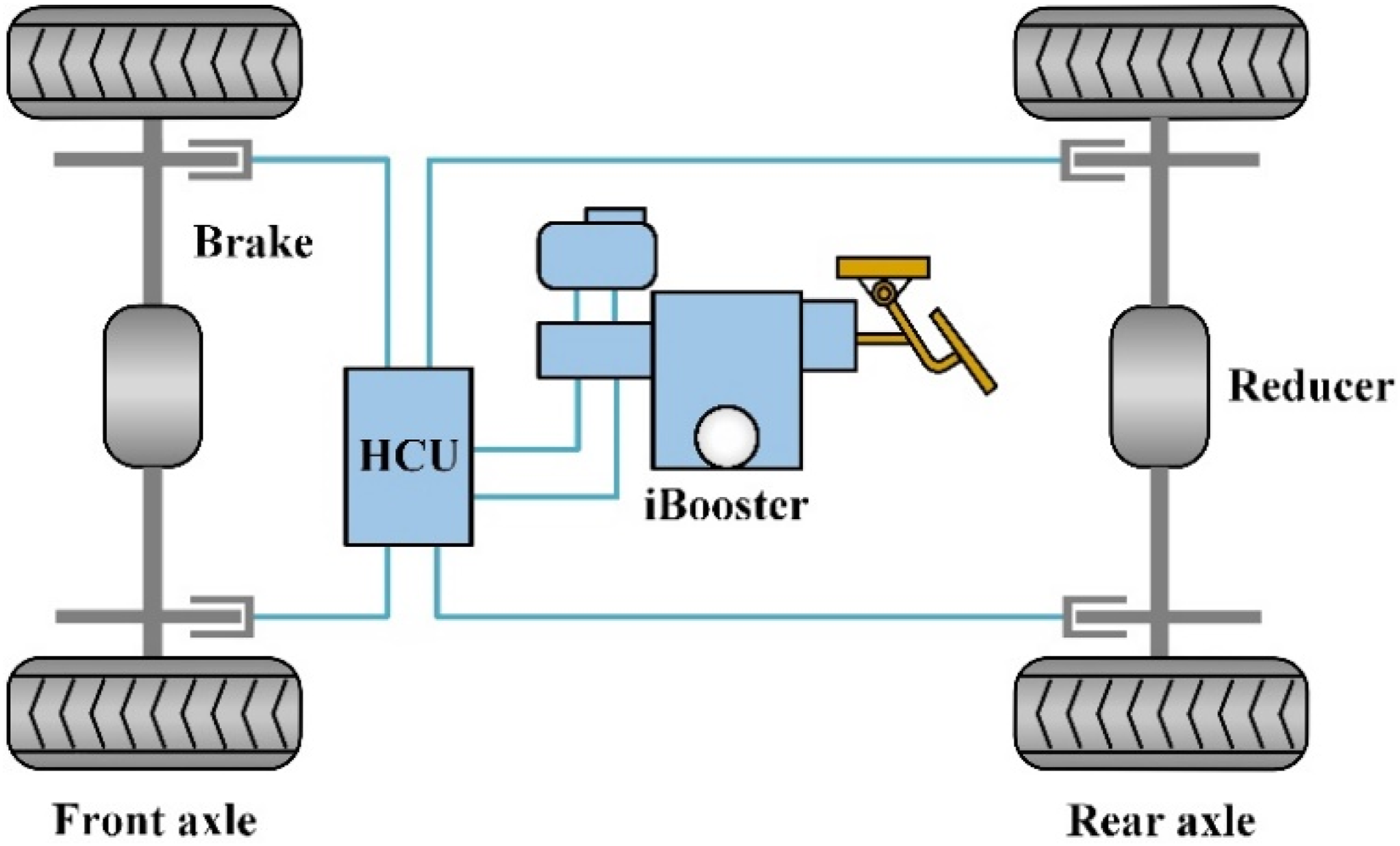
To address the aforementioned issues, this paper develops a high-precision hierarchical control architecture for master cylinder pressure control in the EHB system, as shown in Figure 1. By improving the characterization of nonlinear friction, enhancing external disturbance compensation, and suppressing chattering in SMC, the proposed method achieves high-accuracy tracking of the master cylinder pressure under complex operating conditions. The main contributions of this paper are summarized as follows: (1) A master cylinder pressure dynamic model is established considering nonlinear friction and external disturbances, and a hierarchical control architecture consisting of an upper-level pressure servo loop and a lower-level motor current loop is constructed, decoupling pressure control from motor drive control. (2) To address the limited accuracy of conventional friction modeling, an improved PINN–LuGre friction model is introduced to better capture the system’s nonlinear friction characteristics. On this basis, an ILESO is further incorporated to enable real-time estimation and compensation of external disturbances. (3) Based on the disturbance compensation provided by the ILESO and the nonlinear friction modeling achieved by the PINN–LuGre model, the ISTSMC is employed as the core controller in the upper-level pressure servo loop, while the lower-level motor current loop applies feedforward decoupling control for precise actuation, thereby enabling accurate tracking of the target master cylinder pressure under complex operating conditions. Schematic of the EHB system.
The remainder of this paper is organized as follows. The master cylinder pressure dynamic model is established. The hierarchical control architecture for target pressure tracking is then presented, followed by HiL experimental validation. Finally, the main conclusions are summarized.
2. EHB system modeling
2.1. Motor modeling
To establish the dynamic model of the driving motor in the EHB system, a surface-mounted permanent magnet synchronous motor (PMSM) is employed as the actuation unit. For simplicity, the PMSM is assumed to be ideal, while the effects of magnetic saturation, eddy currents, and hysteresis losses are neglected. Under these assumptions, the voltage equations in the d–q reference frame can be expressed as
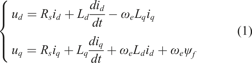
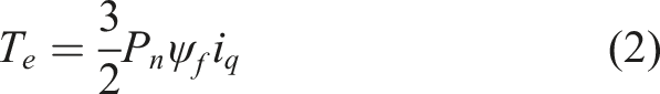
The electromagnetic torque is governed by the q-axis current and can be regulated by adjusting this current, as expressed by
2.2. Mechanical system modeling
Considering that the mechanical part of the EHB system mainly consists of the motor and the reduction mechanism (planetary gear set and ball screw), the torque output of the PMSM is transmitted and amplified through the reduction mechanism during operation. The rotational motion is then converted into linear motion via the ball screw, thereby generating an axial force to drive the movement of the master cylinder piston. Accordingly, the rotational dynamics model of the motor–reduction mechanism and the linear displacement dynamics model of the master cylinder piston can be expressed as follows
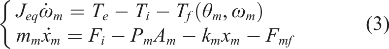
Based on this, the rotational dynamics model of the motor–reduction mechanism can be further expressed as
It should be noted that the magnitude of the master cylinder return spring force is much smaller than that of the system hydraulic pressure and friction forces, and is therefore omitted in equation (5). Moreover,
2.3. Hydraulic system modeling
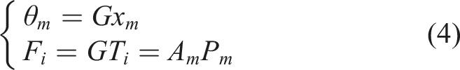
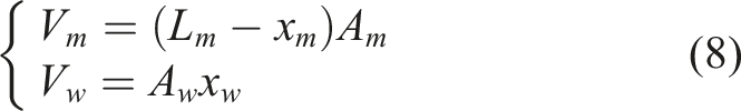
The hydraulic transmission principle of the EHB system is illustrated in Figure 2. During braking, the piston in the brake master cylinder is driven by the motor to pressurize the brake fluid, thereby generating braking pressure. This pressure is transmitted through the brake lines and solenoid valves to the wheel cylinders, where it actuates the pistons to clamp the brake discs and generate the braking force. The flow equations of the master cylinder and wheel cylinders can be expressed as follows Hydraulic schematic of the EHB system.
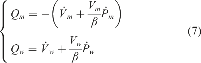
The specific expressions of
The total pressure drop of the EHB system is
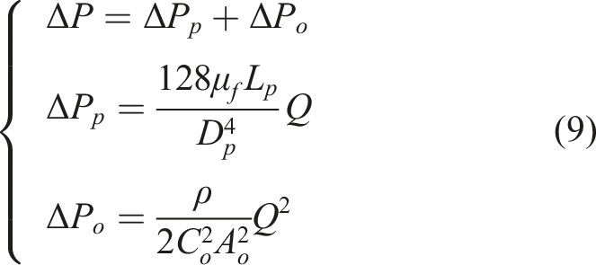
The total pressure drop

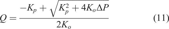
The brake system flow can be derived from equation (10) as
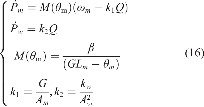
Combining equations (7)–(11), the dynamic pressure model of the brake system can be obtained as
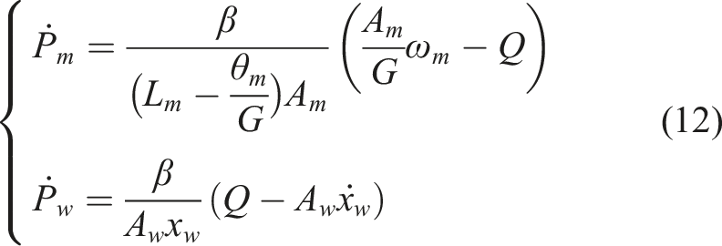
The wheel cylinder clamping process can be expressed as
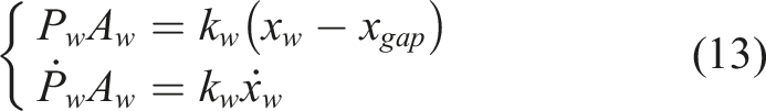
The rate of change of the wheel cylinder pressure is derived from Equations (12) and (13) as
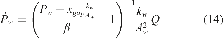
Since
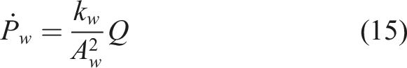
Rearranging equation (12) gives
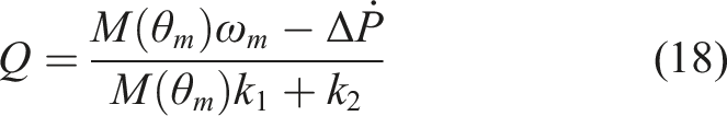
Consequently, the rate of change of the pressure difference in the brake system can be expressed as

The brake system flow can be derived from equation (17) as
Substituting equation (18) into equation (14), the rate of change of the master cylinder pressure is obtained
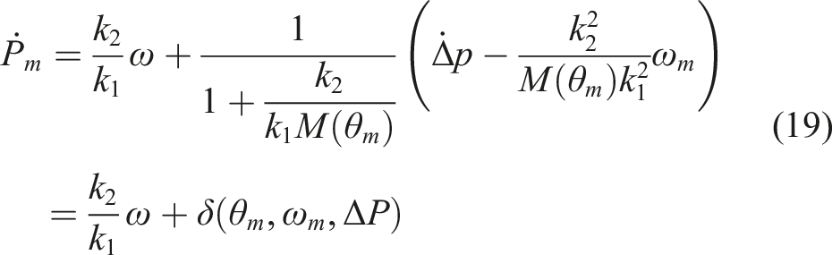
The second term in equation (19) can be regarded as a bounded disturbance
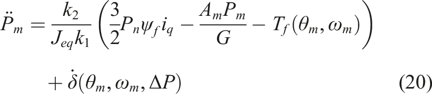
Differentiating equation (19) and combining it with Equations (2) and (5), the dynamic model of the master cylinder pressure can be obtained. This model is used as the control model for the upper-level pressure servo loop and characterizes the relationship between the master cylinder pressure, the electromagnetic torque, the system’s equivalent friction torque, and external disturbances, as follows
3. Hierarchical control architecture design
The system adopts a hierarchical control architecture, as illustrated in Figure 3. The upper layer is a pressure servo loop, where the error between the desired braking pressure Hierarchical control architecture of the EHB braking system.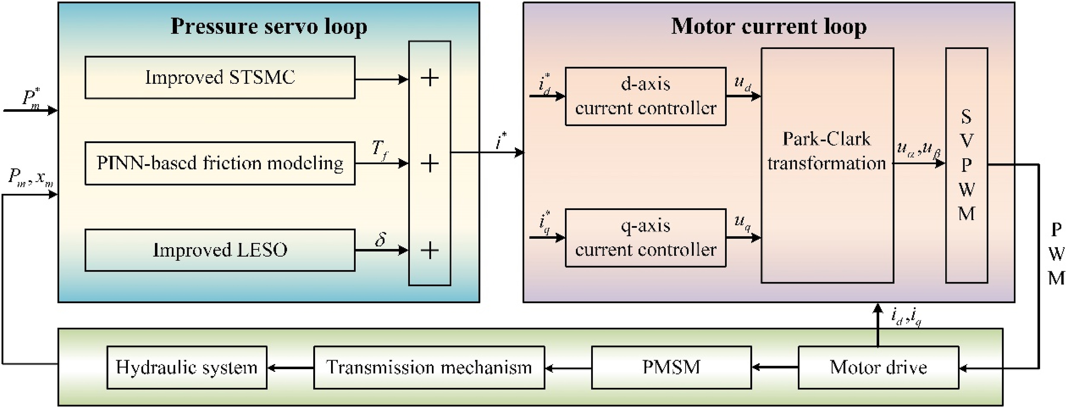
The lower layer is the motor current control loop. Based on the error between the reference current
3.1. Pressure servo loop
Within the above hierarchical control framework, the upper-level pressure servo loop aims to ensure accurate tracking of the desired braking pressure by the master cylinder. Accordingly, an improved super-twisting sliding mode control strategy is developed based on the established master cylinder pressure dynamic model.
To address the influence of nonlinear friction arising from the motor, reduction mechanism, and master cylinder piston on pressure regulation accuracy, the improved PINN-based LuGre friction model shown in Figure 4 is incorporated into the pressure control design, allowing the friction characteristics of the system to be explicitly considered. Meanwhile, an improved linear extended state observer is employed to estimate and compensate for external disturbances that are difficult to model accurately, thereby further enhancing the tracking performance of the pressure servo control. Improved PINN-based LuGre friction model.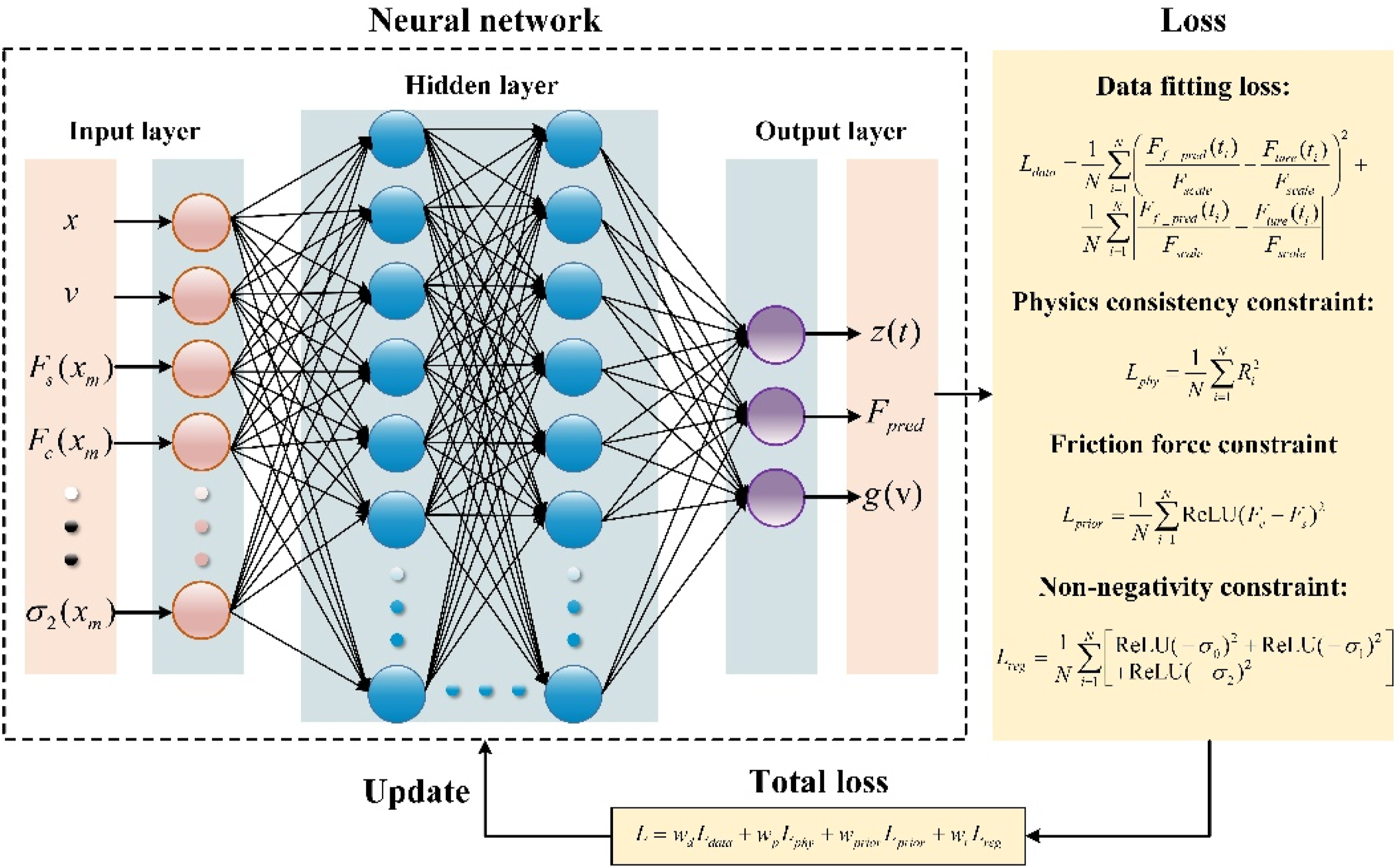
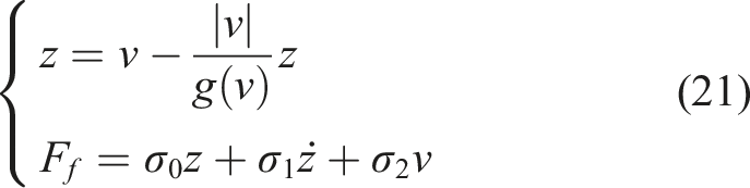
For the modeling of the system equivalent friction torque
In the LuGre friction model,

An improved PINN-LuGre friction model is developed in this study. The model takes the servo cylinder displacement
3.1.1. PINN-based modeling of the internal friction state
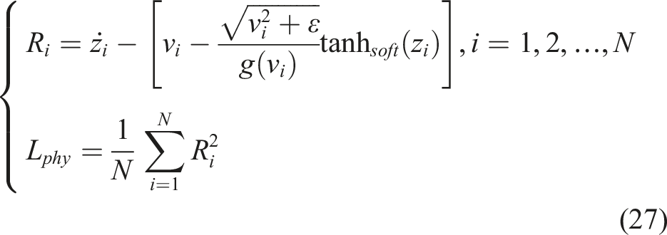
The internal friction state

3.1.2. Improved LuGre elastic term
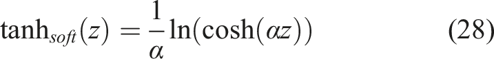
To improve numerical stability and prevent divergence of the elastic term of the friction force

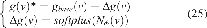
3.1.3. PINN-based adaptive correction of the Stribeck function
To compensate for the data-driven deviations of the LuGre model, a neural network
In addition, the PINN friction model must balance data-fitting accuracy with physical consistency constraints to enhance generalization and interpretability. The implementation is as follows
3.1.3. Physical consistency constraint
The internal friction state
3.1.4. Friction force constrain
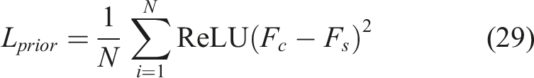
To ensure that the static friction exceeds the Coulomb friction, a prior constraint on the friction force is introduced

3.1.5. Non-negativity constraint on parameters
The friction parameters must be non-negative to ensure the physical realizability of the model, expressed as follows
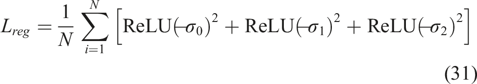

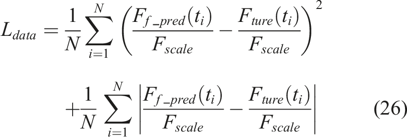
Figure 5 presents the friction torque fitting results of the PINN model. In Figure 5(a), the friction torque predicted by the PINN model is compared with simulation results under different pressure conditions, showing high fitting accuracy across the 1–4 MPa range. As shown in Figure 5(b), the maximum RMS of the pressure tracking error is only 1.19%, further validating the effectiveness of the proposed PINN friction model and its high modeling accuracy. PINN-based friction model under different pressures and corresponding errors.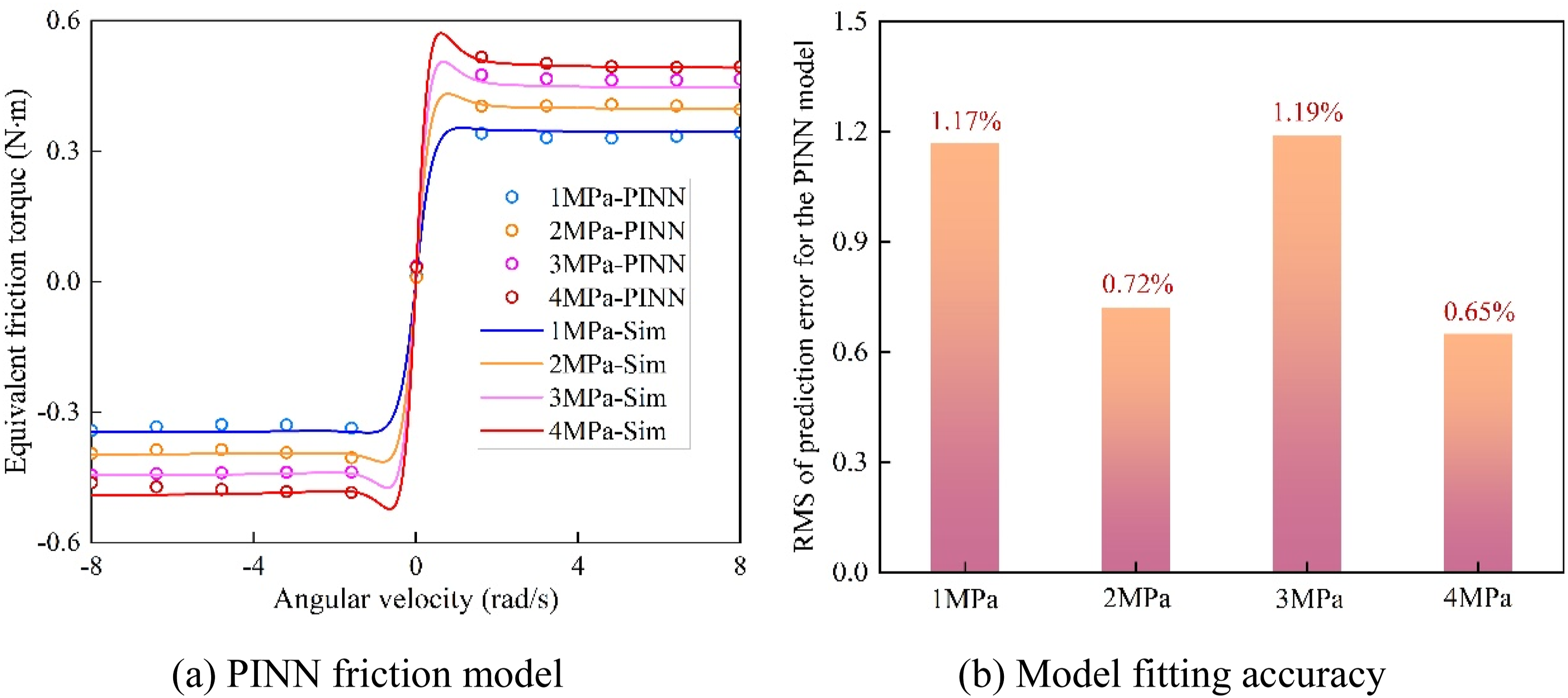
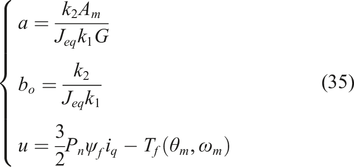
3.1.6. Improved linear extended state observer
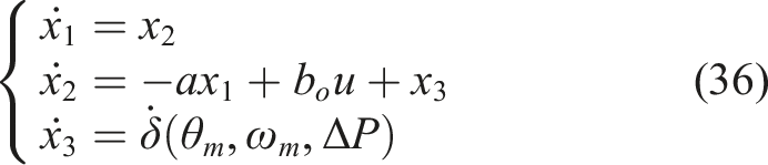
External disturbances are estimated and compensated online using an improved linear extended state observer. Compared with the conventional ESO, it exhibits clear advantages in response speed and estimation accuracy, thereby more effectively mitigating the impact of disturbances on the pressure servo control performance. Based on the upper-level pressure servo control model described in equation (20), the master cylinder pressure
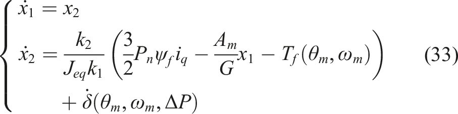
Equation (33) can be further simplified as
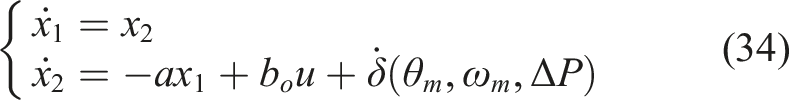
Assume that
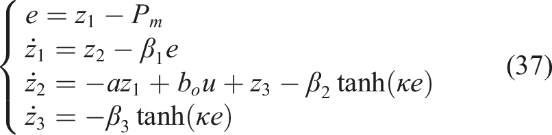
Therefore, an improved LESO is constructed as follows
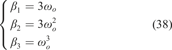
Furthermore, the stability of the improved LESO is analyzed, and the following assumptions are made: (1) (2)
The state observation error is defined as

According to the system characteristics, the following relationship can be obtained

Differentiating equation (40) and substituting it into

Since

By introducing the extended state, the system can be rewritten in a second-order form. Let
The Lyapunov function is chosen as follows
Differentiating equation (44) and substituting it into equation (43) yields
Based on equation (45), a composite Lyapunov function is constructed
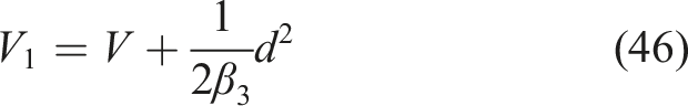
Differentiate

Using Young’s inequality
From the analysis of equation (48), it can be seen that when
3.1.7. Improved super-twisting sliding mode control design
To achieve fast convergence of the pressure tracking error while suppressing the inherent chattering problem of conventional sliding mode control, an improved super-twisting sliding mode controller is designed based on the compensated friction term and the disturbance estimation provided by the ILESO, and is applied to the closed-loop control of the upper-level pressure servo loop. The proposed control strategy effectively leverages the robustness of SMC against parameter uncertainties and external disturbances, as well as its fast dynamic response, to enable the master cylinder pressure
The pressure tracking error is defined as

The conventional super-twisting sliding mode control law can be expressed as
The conventional STSMC algorithm uses a sign function, which produces abrupt changes during switching. This can cause high-frequency chattering and discontinuous control, which may degrade system stability (Yuan et al., 2023). To address this issue, an ISTSMC algorithm is proposed, defined as follows
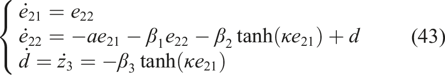
To prove the stability of the ISTSMC, the following nonlinear function is defined

A new state variable is introduced as follows
Differentiating equation (53) and substituting equation (51) yields
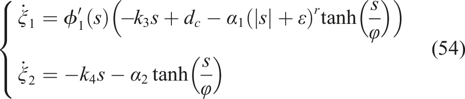
The system can be further expressed as
To prove that
Since

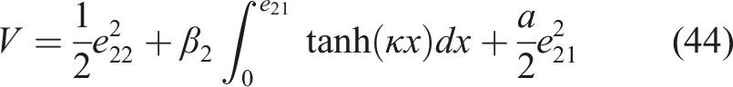
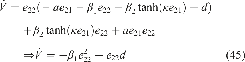
The Lyapunov function is designed as follows

Differentiating equation (57) yields
Since

According to Lyapunov’s theorem, the system satisfies the conditions for asymptotic stability and is therefore asymptotically stable.
3.2. Motor current loop
The motor current loop serves as the inner control layer of the system, primarily responsible for tracking the target current commands generated by the upper pressure servo loop, thereby enabling precise motor actuation and rapid pressure buildup in the EHB braking system. For the PMSM, a vector control strategy is adopted for current regulation, and the corresponding control framework is illustrated in Figure 6. Block diagram of the motor current loop control architecture.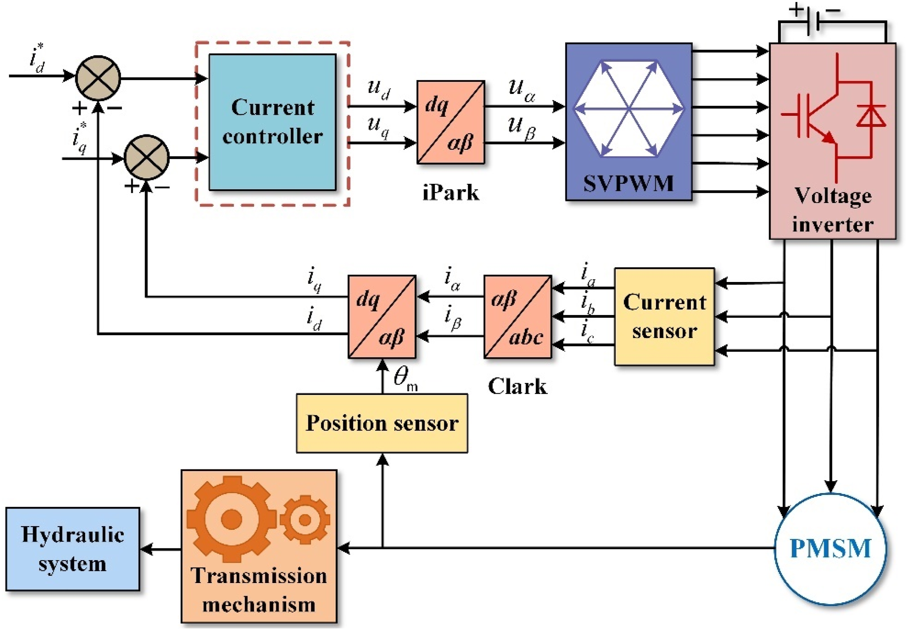
During operation, the three-phase stator currents
Considering the structural characteristics of the surface-mounted permanent magnet synchronous motor (SPMSM) employed in the EHB braking system, the vector control strategy fully exploits the permanent-magnet flux to achieve decoupled control of electromagnetic torque and flux linkage, thereby enhancing the system’s dynamic response and operating efficiency. For PMSM current regulation, an
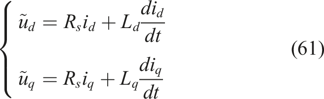
Before designing the current controller, the PMSM voltage equations in equation (1) need to be decoupled, as shown in Figure 7. As indicated in equation (1), in the Block diagram of the decoupled control for electromagnetic coupling.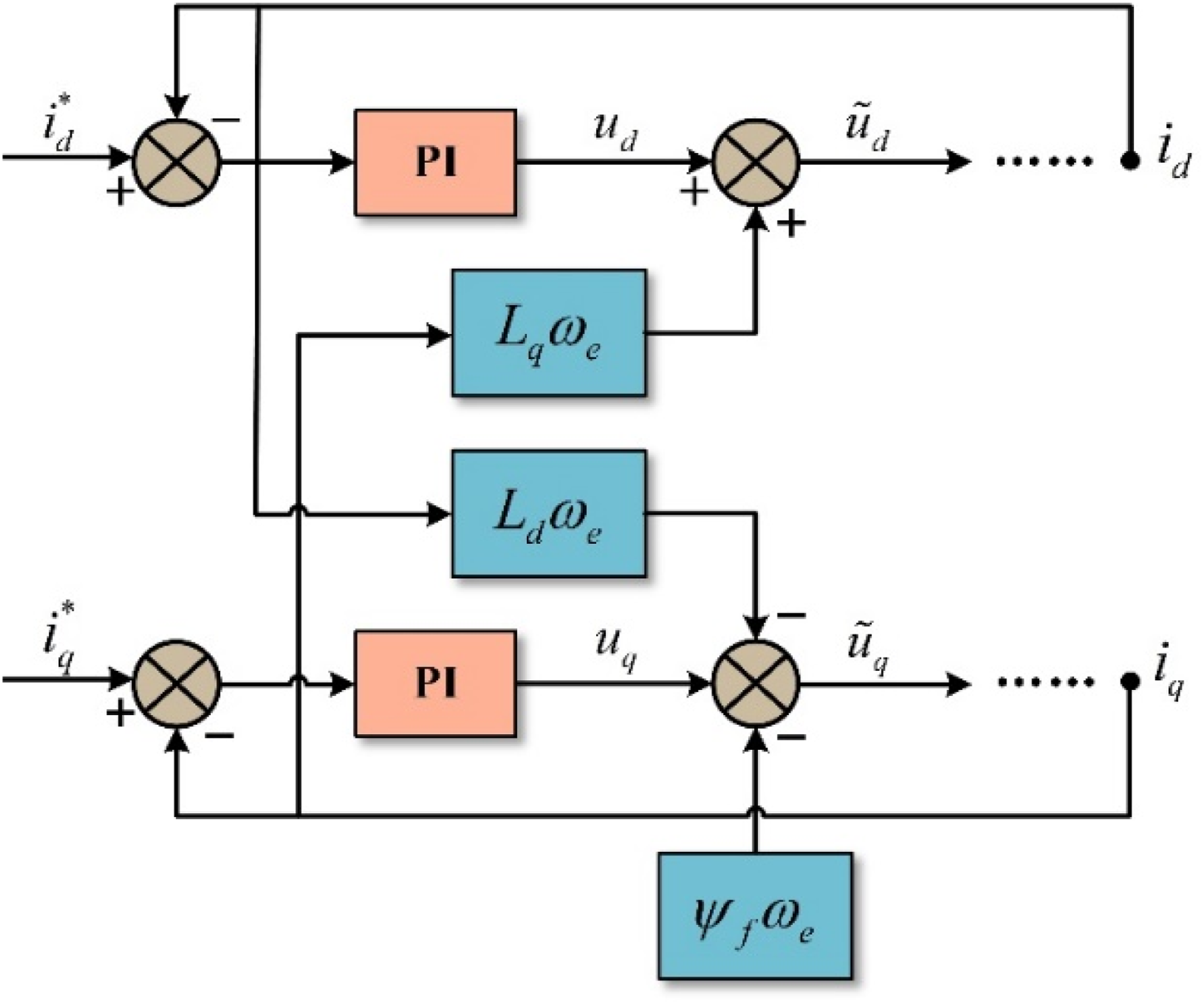
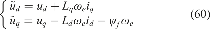
Therefore, the decoupled
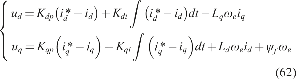
Based on this analysis, separate PID controllers are designed for the
4. Experimental validation and analysis
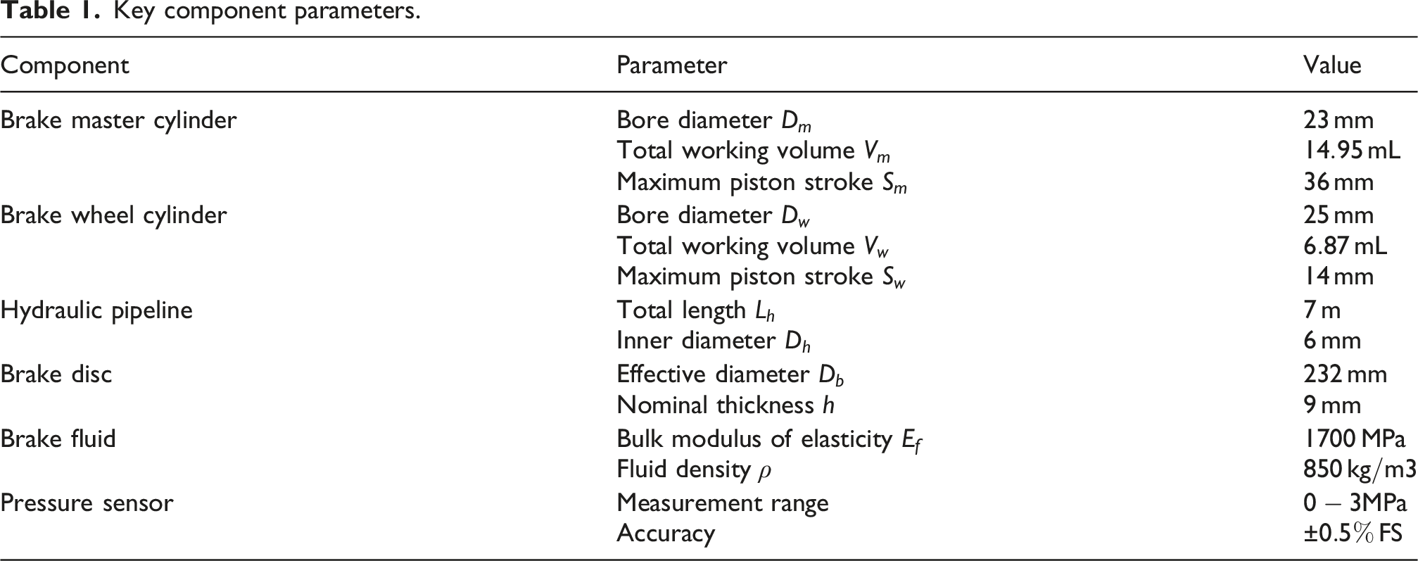
To validate the effectiveness of the proposed brake pressure control strategy in actual braking scenarios, ramp, step, and low- and high-frequency sinusoidal profiles were designed with a target pressure of 3 MPa, and corresponding master cylinder pressure HiL tests were conducted, as shown in Figure 8. Figure 8(a) illustrates the architecture of the HiL platform. The platform consists of a host computer and brake system hardware, with the iBooster brake actuator and hydraulic control unit (HCU) as its core components. Through the coordinated operation of the brake pedal, master cylinder, wheel cylinders, hydraulic lines, calipers, brake discs, and pressure sensors, the platform achieves the complete functionality from driver command to vehicle braking, and the parameters of each component are listed in Table 1. Executing the brake pressure control model on the host computer enables precise regulation of the master cylinder pressure. Test data were collected using the SCALEXIO AutoBox, as shown in Figure 8(b), at a sampling rate of 200 Hz, enabling real-time recording and synchronous acquisition of CAN bus and analog signals. HiL tests. Key component parameters.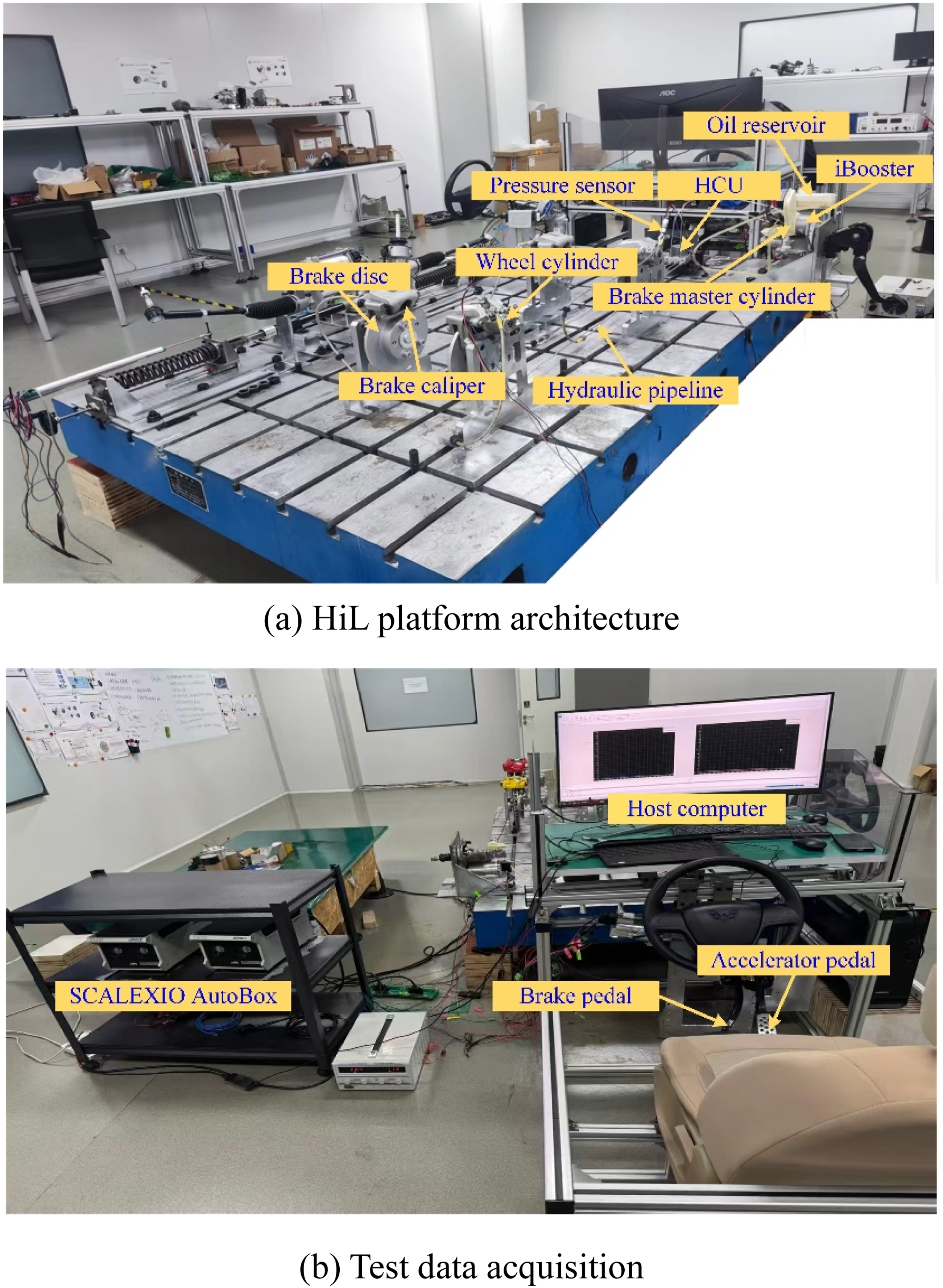
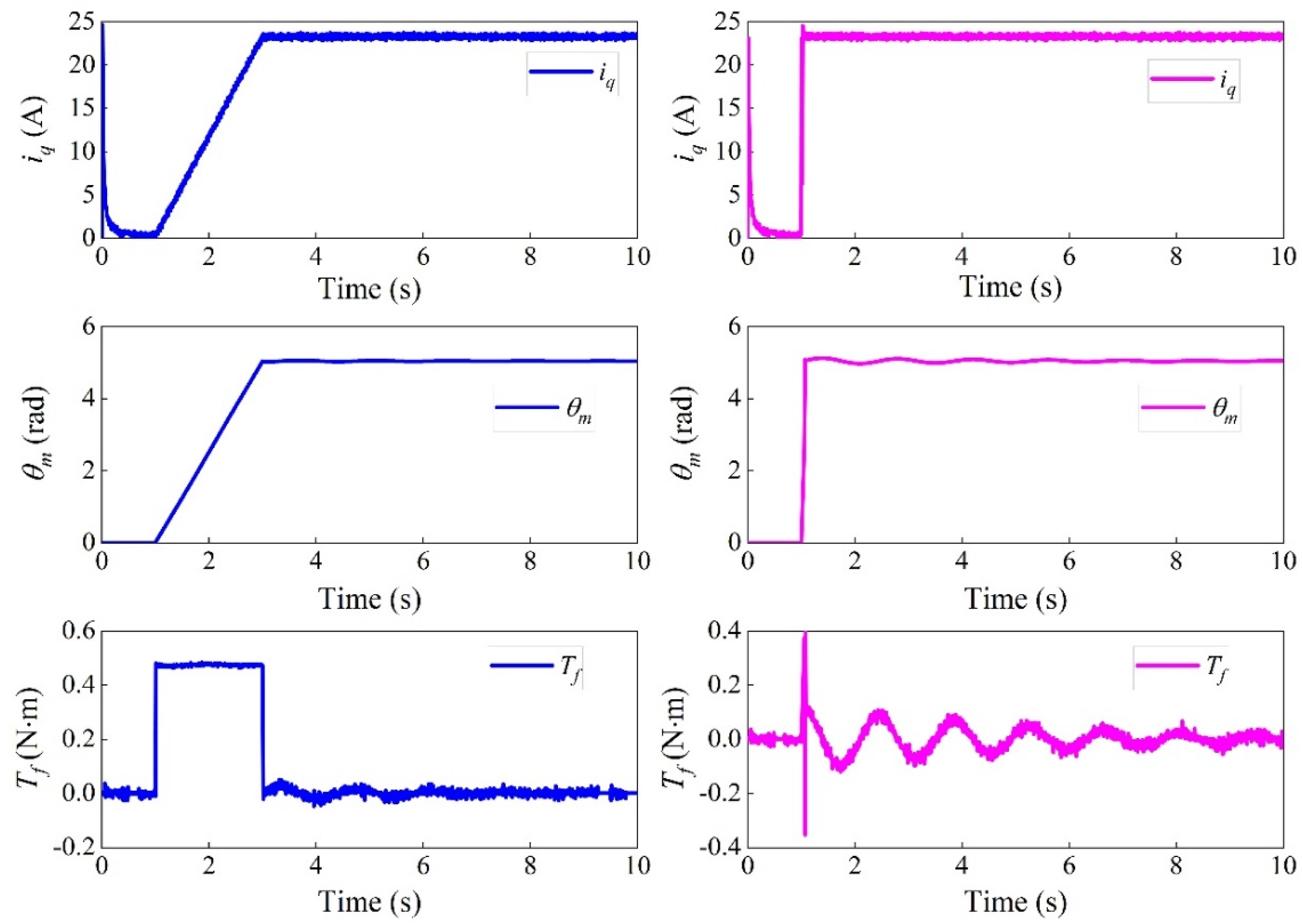
Figures 9 and 10 present the test results from the HiL platform. As shown in Figure 9, whether under the ramp input in Figure 9(a) or the step input in Figure 9(b), the proposed brake pressure control strategy achieves precise tracking of the 3 MPa target pressure. As illustrated in Figure 9(b), the maximum pressure tracking error does not exceed 0.05 MPa, satisfying the accuracy requirements for brake pressure control and thereby validating the correctness and feasibility of the proposed control strategy. Brake pressure test results under ramp and step inputs. Key state variable responses under ramp and step inputs.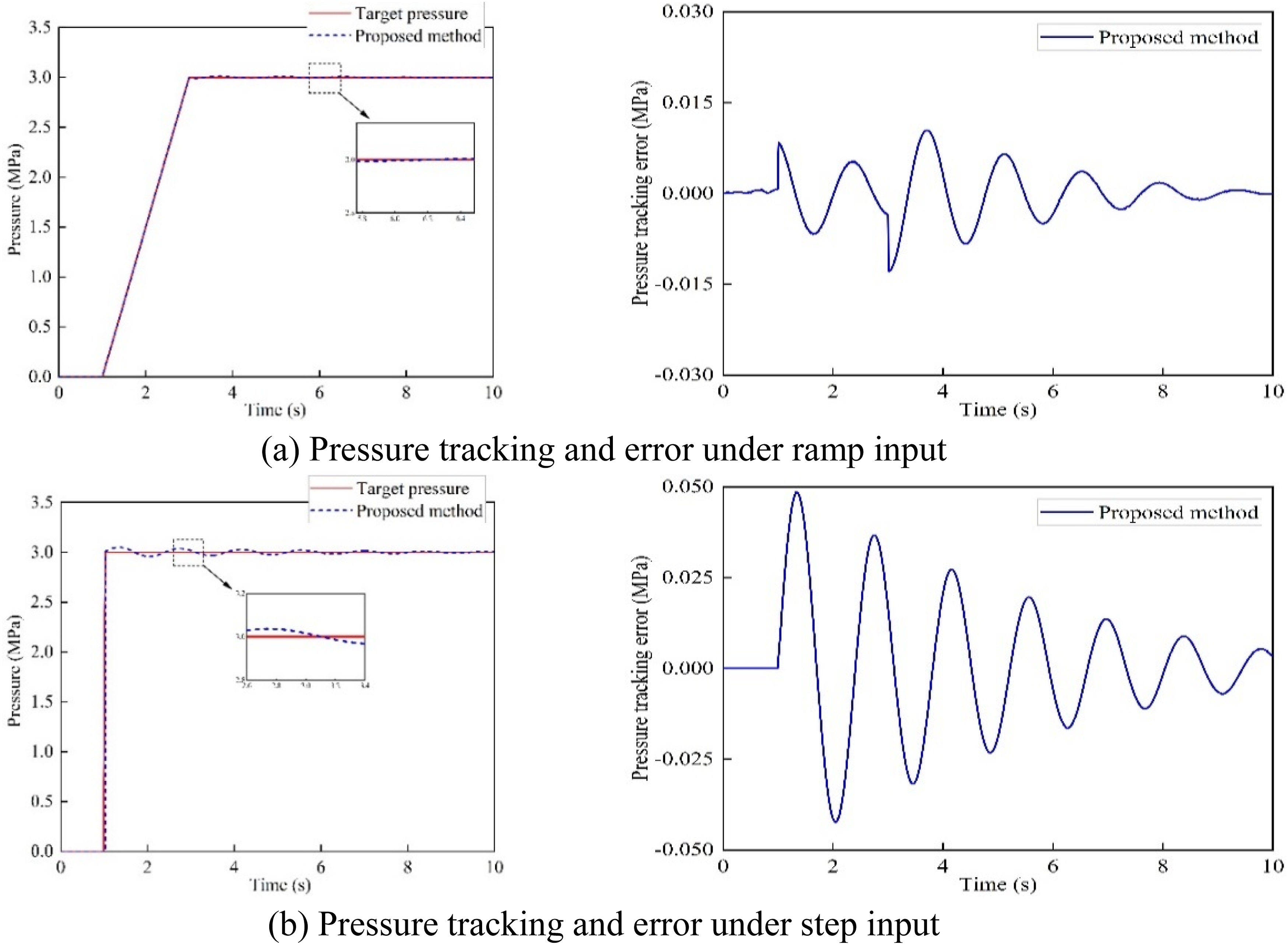
As shown in Figure 11, the braking pressure control performance of the proposed strategy is illustrated under ramp and step operating conditions without the PINN–LuGre model and the ILESO. From Figures 11(a) and (b), when the PINN–LuGre model is not used to characterize the system’s nonlinear friction, the brake pressure exhibits pronounced fluctuations. In addition, when the ILESO is not used for real-time disturbance estimation and compensation, the system cannot accurately track the target brake pressure. These results confirm the effectiveness of the proposed hierarchical control architecture. Influence of PINN–LuGre and ILESO on pressure control performance.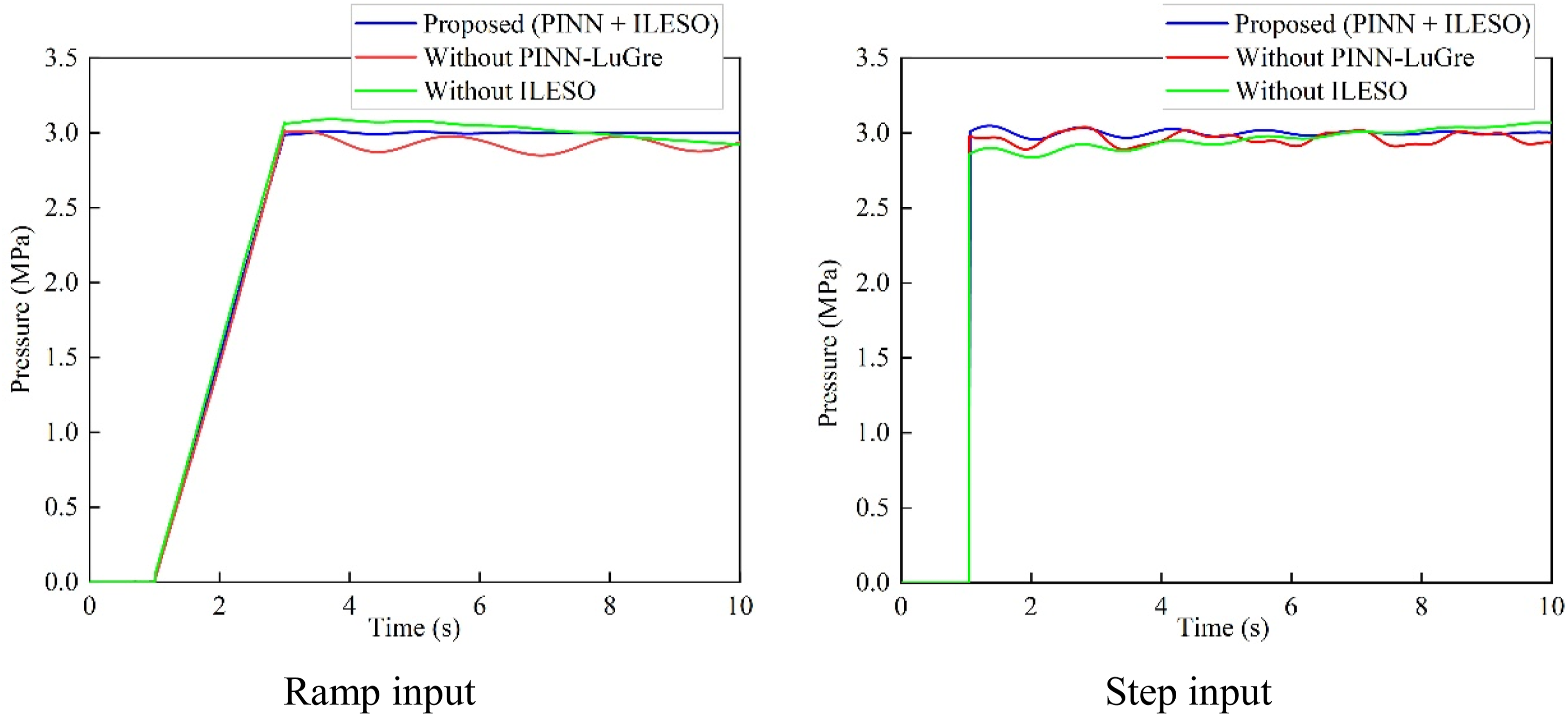
To further validate the proposed control strategy’s performance under complex operating conditions and varying reference inputs, tests are conducted under low- and high-frequency sinusoidal conditions, as shown in Figure 12. The specific formulations of the conventional SMC and STSMC controllers are given in (Ayinalem and Kassie, 2025). The zoomed-in sections of the pressure tracking curves clearly indicate that the proposed brake pressure control strategy maintains high tracking accuracy. Furthermore, the pressure error curves in Figure 12 show that, compared with conventional SMC and STSMC control, the proposed strategy produces smaller error fluctuations and can accurately track both low- and high-frequency sinusoidal pressure profiles. These results confirm the superior control performance of the proposed strategy. Brake pressure test results under low- and high-frequency sinusoidal inputs.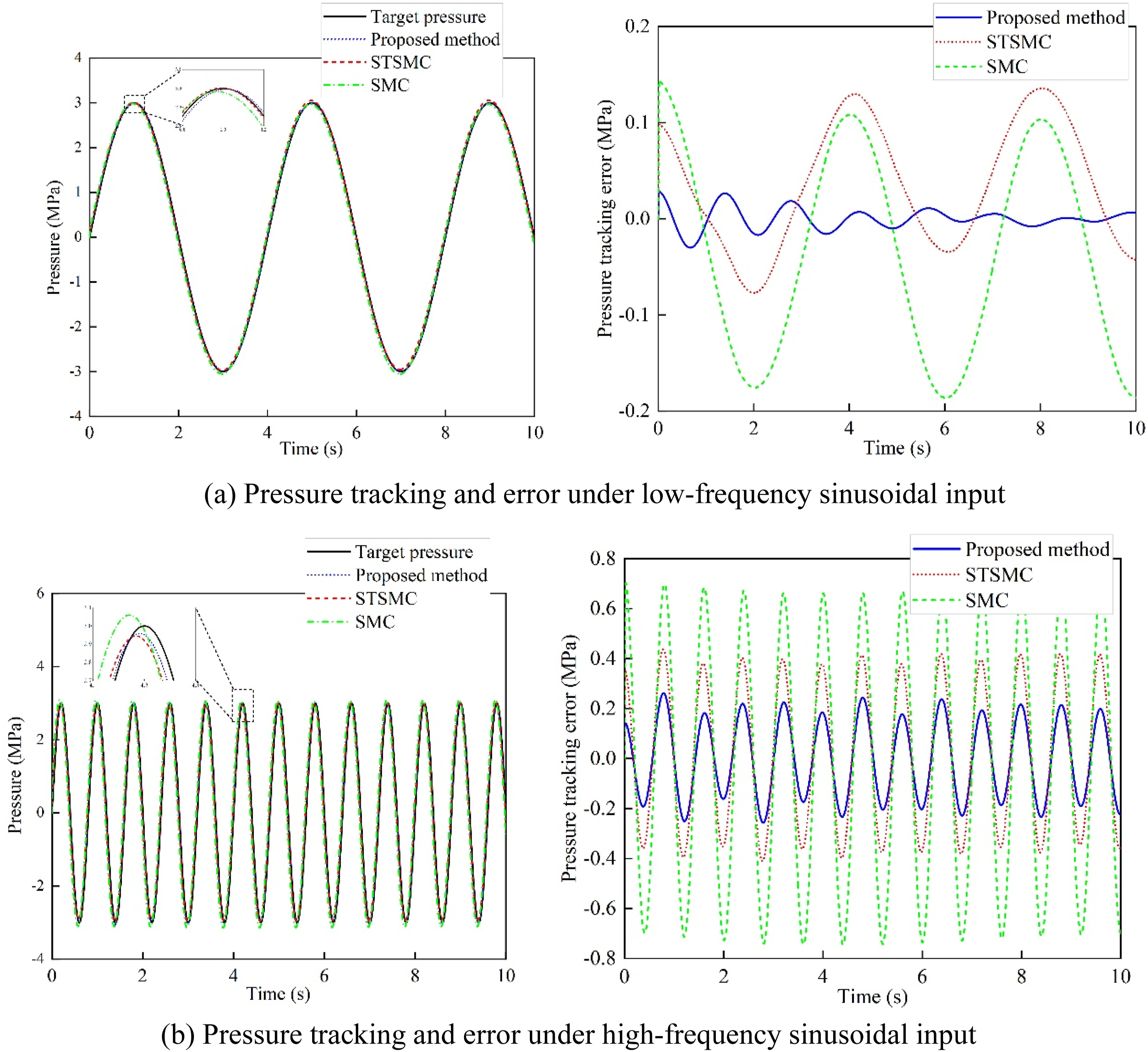
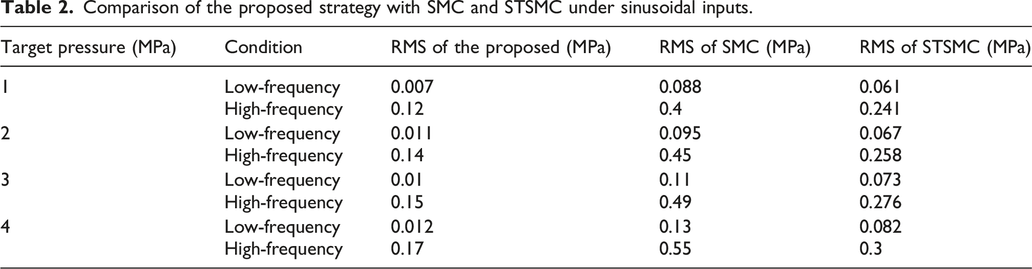
Comparison of the proposed strategy with SMC and STSMC under sinusoidal inputs.
5. Conclusion
As the fundamental actuation loop of the EHB system, precise brake pressure control plays a critical role in determining the dynamic performance of the braking system. Therefore, a hierarchical control architecture is developed to achieve accurate tracking of the target pressure under complex operating conditions. The upper-level pressure servo loop enhances the system’s capability in characterizing nonlinear friction through an improved PINN–LuGre friction model and incorporates an ILESO for real-time estimation and compensation of external disturbances. On this basis, an ISTSMC is introduced to achieve robust pressure tracking control. The lower-level motor current loop employs feedforward decoupling control to ensure accurate current tracking, thereby providing high-precision actuation support for the upper-level pressure control. This hierarchical control architecture enables high-precision and stable brake pressure tracking under complex nonlinear and disturbed conditions. HiL tests validate the effectiveness of the proposed pressure control strategy. Compared with conventional SMC and STSMC methods, the proposed strategy achieves higher tracking accuracy with reduced error fluctuations. Under step inputs, the maximum pressure error remains below 0.05 MPa, while under low- and high-frequency sinusoidal inputs, the RMS errors are 0.01 MPa and 0.15 MPa, respectively. Relative to the SMC method, the errors are reduced by approximately 90.9% and 69.4%, respectively, while reductions of about 86.3% and 45.7% are obtained compared with the STSMC method. These results further validate that the proposed strategy enables stable and high-precision pressure tracking across different operating conditions.
This study achieves high-precision and stable brake pressure tracking, providing a novel solution for pressure control in EHB systems under complex operating conditions and offering a valuable reference for future related research. However, the present work relies on a reduced-order EHB model for controller design and real-time implementation, and thus does not explicitly capture some high-order nonlinearities, coupling effects, and temperature- or wear-dependent friction variations. In addition, real-vehicle experimental validation has not yet been performed. Future work will focus on extending the framework to more complex dynamics and validating it in real vehicle experiments.
Footnotes
Funding
The authors disclosed receipt of the following financial support for the research, authorship, and/or publication of this article: This work was supported by the National Key R&D Program of China (No. 2023YFB2504500), the National Natural Science Foundation of China (Nos. 52472410 and 52502526), and the Natural Science Foundation of Jiangsu Province (No. BK20250841).
Declaration of conflicting interests
The authors declared no potential conflicts of interest with respect to the research, authorship, and/or publication of this article.