Abstract
The time-varying contact stiffness at the spindle-holder-tool joint in a magnetic levitation milling spindle significantly affects system dynamics during high-speed machining. To address this issue, a dynamic model of the rotor system is developed by integrating Timoshenko beam theory, rotor dynamics, and joint contact theory. The joint interface is modeled using distributed spring-damping elements, and the influence of centrifugal expansion on contact stiffness degradation is analyzed. The model incorporates the effects of magnetic bearing support stiffness, gyroscopic moments, and milling force excitation. The dynamic response is obtained using time-domain numerical integration. Results indicate that increasing rotational speed reduces joint contact stiffness, alters mode shapes, and amplifies tool tip vibration amplitudes, thereby diminishing the system’s vibration resistance and increasing the risk of instability. This study provides a theoretical foundation for improving the stability and dynamic performance of high-speed magnetic levitation spindles.
Keywords
1. Introduction
Magnetic levitation milling spindles are increasingly employed in ultra-precision machining, such as aerospace manufacturing, due to their contact-free support, lubrication-free, and high rotational speed capabilities. The dynamic behavior of the spindle system directly influences machining accuracy and operational stability. Among various factors, the connection performance of the spindle-holder-tool joint plays a critical role in determining the overall dynamic characteristics (Ertürk et al., 2007a, 2007b; Salahshoor and Ahmadian, 2009). During high-speed machining, the joint interface is susceptible to stiffness degradation and dynamic instability (Gagnol et al., 2011). It has been reported that 25-50% of the total tool tip deformation originates from joint interfaces (Shamine and Shin, 2000). Therefore, accurate modeling of the joint’s dynamic characteristics and investigation of its vibration response are essential for improving machining stability and precision.
Considerable research has been devoted to the dynamic modeling and parameter identification of spindle-holder-tool systems. Experimental techniques, particularly impact hammer testing, are widely used to identify dynamic parameters due to their simplicity and efficiency (Iglesias et al., 2022). In milling dynamics modeling, this approach is frequently applied to determine modal parameters such as stiffness, damping, and modal mass at the tool tip (Li et al., 2020). For modeling contact stiffness at the spindle-holder interface, Namazi et al. (2007) proposed a Timoshenko beam-based method using uniformly distributed translational and rotational springs to quantify radial and rotational stiffness and identified spring parameters by minimizing errors in spindle assembly experiments. Xu et al. (2014) incorporated clamping and centrifugal forces into their model and identified axial and radial joint stiffness experimentally. Similarly, considering flexible deformation effects, Zhao et al. (2024) investigated the contact characteristics of mechanical transmission systems, highlighting the significant influence of structural compliance on interface stiffness. In addition, frequency response function (FRF) identification methods have been widely used to analyze the dynamic behavior of spindle interfaces. For instance, Özşahin et al. (2009) used tool tip FRF to evaluate the influence of spindle-holder interface stiffness on vibration amplitude. Du et al. (2015) proposed an ultrasonic method to examine the effects of nominal contact area, contact pressure distribution, and interface stiffness on tool tip vibration.
In addition to experimental approaches, analytical models have been developed to predict joint dynamics (Sakamoto et al., 2012). Ertürk et al. (2006) presented an analytical algorithm based on Timoshenko beam theory, calculating point interface contact stiffness through electro-nano coupling and structural modification. Zhao et al. (2013) developed a dynamic model of the spindle rotor system considering contact at tool-jacket, jacket-holder, and holder-spindle interfaces. Using Euler-Bernoulli beam theory, Luo et al. (2022) segmented the spindle-holder system into three substructures and applied the transfer matrix method together with multi-point response coupling to predict the end FRF. Kiran (2022) treated the holder-tool joint as a flexible component and proposed a frequency response coupling analysis accounting for all translational and rotational mechanical characteristics. Liu et al. (2019) and Cui and Su (2020) developed analytical models of contact stiffness at the holder-tool interface using fractal and multi-scale contact theories and integrated them with finite element models to predict chatter stability. Miao et al. (2023) employed a distributed nonlinear spring-damper model to describe the contact behavior at spindle-holder-tool joints, deriving a stiffness matrix dependent on vibration displacement via fractal theory and the slicing method. Furthermore, nonlinear dynamic behavior and vibration characteristics of mechanical systems under complex operating conditions have been extensively studied, demonstrating that contact nonlinearity plays a crucial role in system dynamic response (Zhao et al., 2025a). In addition, related studies on contact modeling and system reliability provide further insights into the coupling between interface stiffness and overall dynamic performance (Zhao et al., 2023, 2025b).
Although existing studies have provided valuable insights into spindle dynamics, several critical issues remain insufficiently addressed, particularly for magnetic levitation milling spindles.
First, most previous research has focused on conventional spindle systems supported by rolling bearings, whose boundary conditions and support characteristics differ significantly from those of magnetic levitation systems. The absence of mechanical contact in magnetic bearings leads to fundamentally different dynamic behaviors, which are not adequately captured by existing models.
Second, the evolution mechanism of joint contact stiffness under high-speed operating conditions has not been clearly quantified. In particular, limited theoretical work has been conducted on the stiffness variation of the spindle-holder-tool joint under the combined effects of centrifugal forces and drawbar preload variation. As a result, the mechanism of stiffness degradation at high rotational speeds remains unclear.
Third, the relationship between joint stiffness variation and system dynamic response, especially under varying rotational speeds, has not been systematically investigated. This limitation restricts the accurate prediction of vibration characteristics and the effective optimization of system performance.
These issues make it difficult to accurately predict the dynamic behavior of magnetic levitation spindle systems under high-speed operating conditions. To address these issues, this study develops a comprehensive dynamic model of a magnetic levitation milling spindle system that incorporates the variable stiffness characteristics of the spindle-holder-tool joint. The main contributions of this work are summarized as follows: (1) A coupled dynamic model of a magnetic levitation spindle system considering the spindle-holder-tool joint characteristics is established. (2) The stiffness variation of the joint induced by centrifugal effects is systematically analyzed based on elastic theory. (3) The influence of joint stiffness variation on the dynamic response of the system is quantitatively evaluated under different rotational speeds.
The results of this study provide a theoretical basis for the design optimization and stability improvement of high-speed magnetic levitation milling spindles.
2. Dynamic model of magnetic levitation milling electric spindle
Figure 1(a) illustrates the structure of the magnetic levitation milling spindle. The main components include the spindle, front and rear radial magnetic bearings, motor rotor, holder, collet (jacket), lock nut, and cutter. The inner conical surface of the spindle and the outer conical surface of the holder are held together by the drawbar pulling force. The holder and collet are fixed onto the holder via the lock nut. The motor supplies driving torque to the spindle, while the radial magnetic bearings provide electromagnetic support to achieve stable suspension. Spindle-holder-tool system.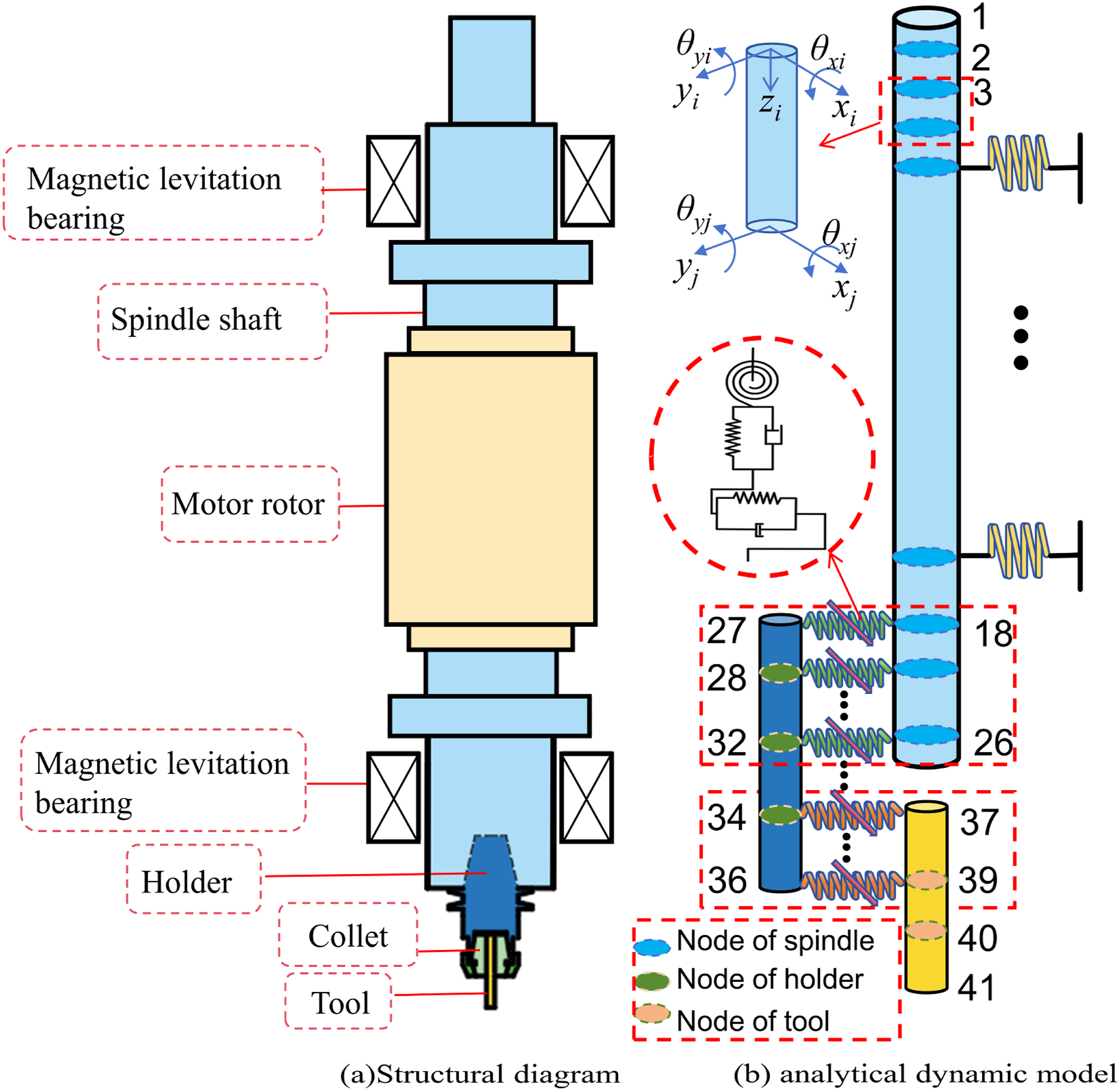
To analyze the contact characteristics of the joint, the finite element method is used to discretize the spindle-holder-tool system into interconnected “mass-spring-damping” elements, as shown in Figure 1(b).
In Figure 1(b), in order to quantify the elastic deformation of the joint under milling loads, the tapered joint is divided into stepped shaft segments, and the straight-shank end mill is simplified as a uniform circular cross-section beam element. Axial displacements caused by radial deformations are neglected. The system is ultimately represented by 2-node, 8-degree-of-freedom Timoshenko beam elements, each node having translational degrees of freedom along the x- and y-axes and rotational degrees of freedom about the x- and y-axes. The spindle-holder and holder-tool joints are modeled using distributed nonlinear spring-damper elements, while the magnetic bearing support is introduced with equivalent electromagnetic stiffness. The spindle-magnetic bearing interface is modeled using a 4-DOF nonlinear stiffness formulation.
2.1. Dynamic model of the spindle-holder taper joint
When the spindle and the holder are combined, they are subject to the pulling force of the drawbar. Therefore, when it rotates, there are mechanical characteristics such as contact surface positive pressure, torsional moment, and conical surface friction force between its joint surfaces. When modeling, based on the finite element method, each conical unit is first simplified into a Timoshenko beam with an equivalent diameter of its median diameter, and then based on the force characteristics of each beam element node, it is simplified into a spring-damping model, as shown in Figure 2. Distributed spring-damping model of the spindle-holder joint.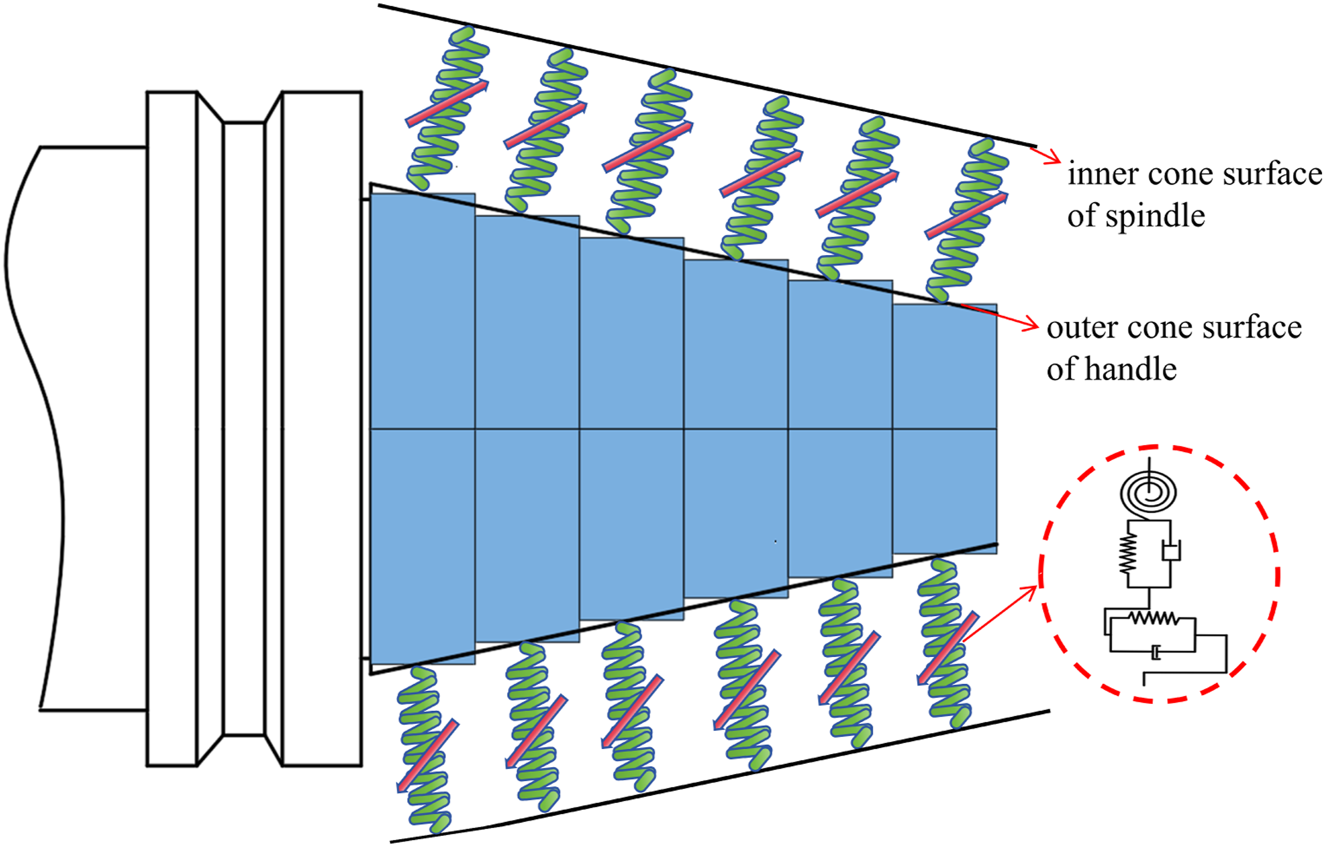
According to Figure 2, when analyzing the stress characteristics of each Timoshenko beam unit node on the conical surface of the spindle-tool holder joint, if the nodes on the spindle are represented by and the nodes on the holder are represented by, then the radial force, axial force, torque, friction, etc., experienced by each node are represented by springs, torsion springs, and damping in turn. The equivalent physical model is shown in Figure 3. Distributed spring-damping node coupling model.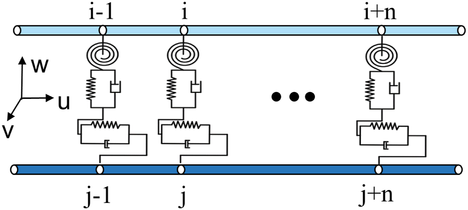
However, during the operation of the magnetic levitation electric spindle, the spindle-holder joint will produce corresponding displacements under the action of force and torque, which is reflected in Figure 3 as corresponding elastic deformation, which in turn triggers the mutual coupling of forces and moments between each node.
In order to describe the coupling relationship between the force and torque of each joint surface during rotation, when the
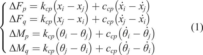
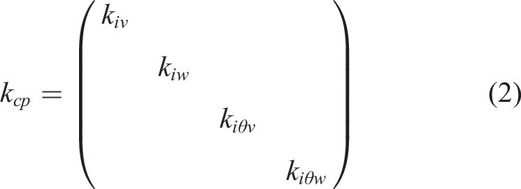
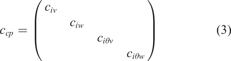
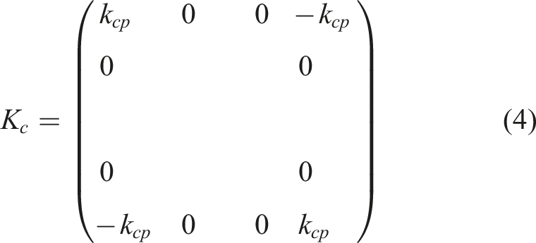
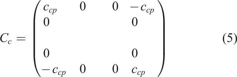
The overall stiffness matrix and overall damping matrix of the spindle-holder joint can be expressed as:
2.1.1. Static contact stiffness model of spindle-holder joint
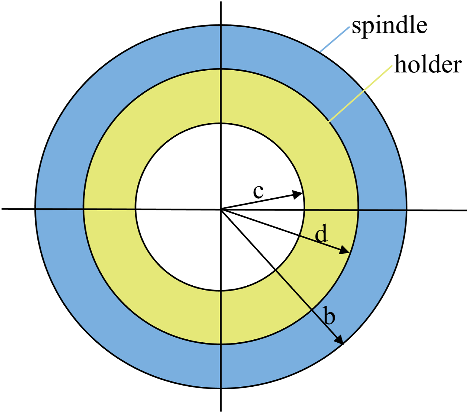
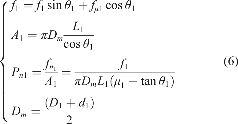
As shown in Figure 4, under static conditions, the pretightening force Stress analysis diagram of the spindle-tool holder joint.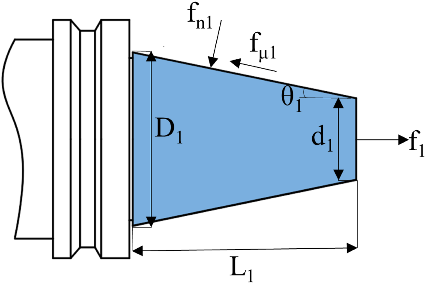
Assuming that the conical contact pressure between the spindle and the holder is uniformly distributed along the axial direction, then according to the conical contact mechanics theory, the contact pressure per unit area
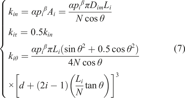
According to the relationship between the contact pressure and contact stiffness of the joint in the literature (Zhao et al., 2013), and using the finite element method to discretize the joint surface into
2.1.2. Dynamic stiffness model of spindle-holder joint
When the spindle is stationary, the spindle-holder joint surface produces an interference fit under the tension of the broach rod, forming an initial interference amount
When the spindle rotates at high speed, due to the hollow conical structure of the spindle joint and the solid conical structure of the tool holder, the deformation difference between the spindle and the tool holder at any contact position will cause the axial distribution of the interference at the joint to change. This results in a centrifugal expansion effect as shown in Figure 5. Simplified diagram of the centrifugal expansion of the spindle-holder joint.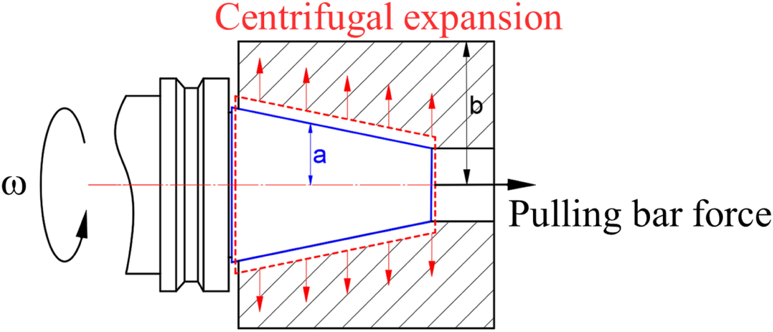
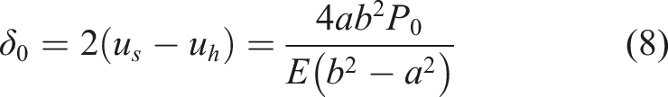
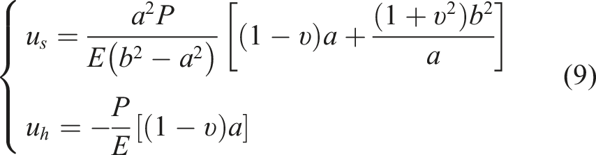
According to the elastic deformation theory (Xu and Liu, 1995), the deformation expression of the spindle-holder joint at any contact point on the tapered surface shown in Figure 5 is:
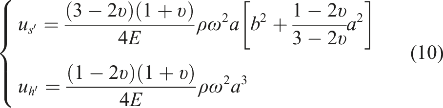
Furthermore, according to formula (10), the expression for the radial gap
The dynamic contact pressure
From this, the expression of the contact pressure
From equation (13), the variable stiffness model of the spindle-holder joint can be obtained by integrating the pressure of each shaft segment unit and bringing it into equation (7).
2.2. Construction of dynamic model of holder-tool joint
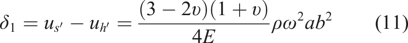
The holder-tool joint is structurally composed of a tool holder, a collet, a lock nut, and a tool. Torque is applied through the lock nut, and the tool is assembled to the tool holder through an elastic jacket. In order to describe the contact relationship between the tool holder and the tool, a distributed spring-damping model is used to replace the jacket to simulate the contact characteristics between the tool holder and the tool, as shown in Figure 6. Distributed spring-damping model of tool holder-tool joint.
Assuming a uniform distribution of pressure at the contact interface among the tool, tool holder, jacket, and preload nut joint, where the tool diameter is denoted as Stress analysis diagram of holder-tool joint.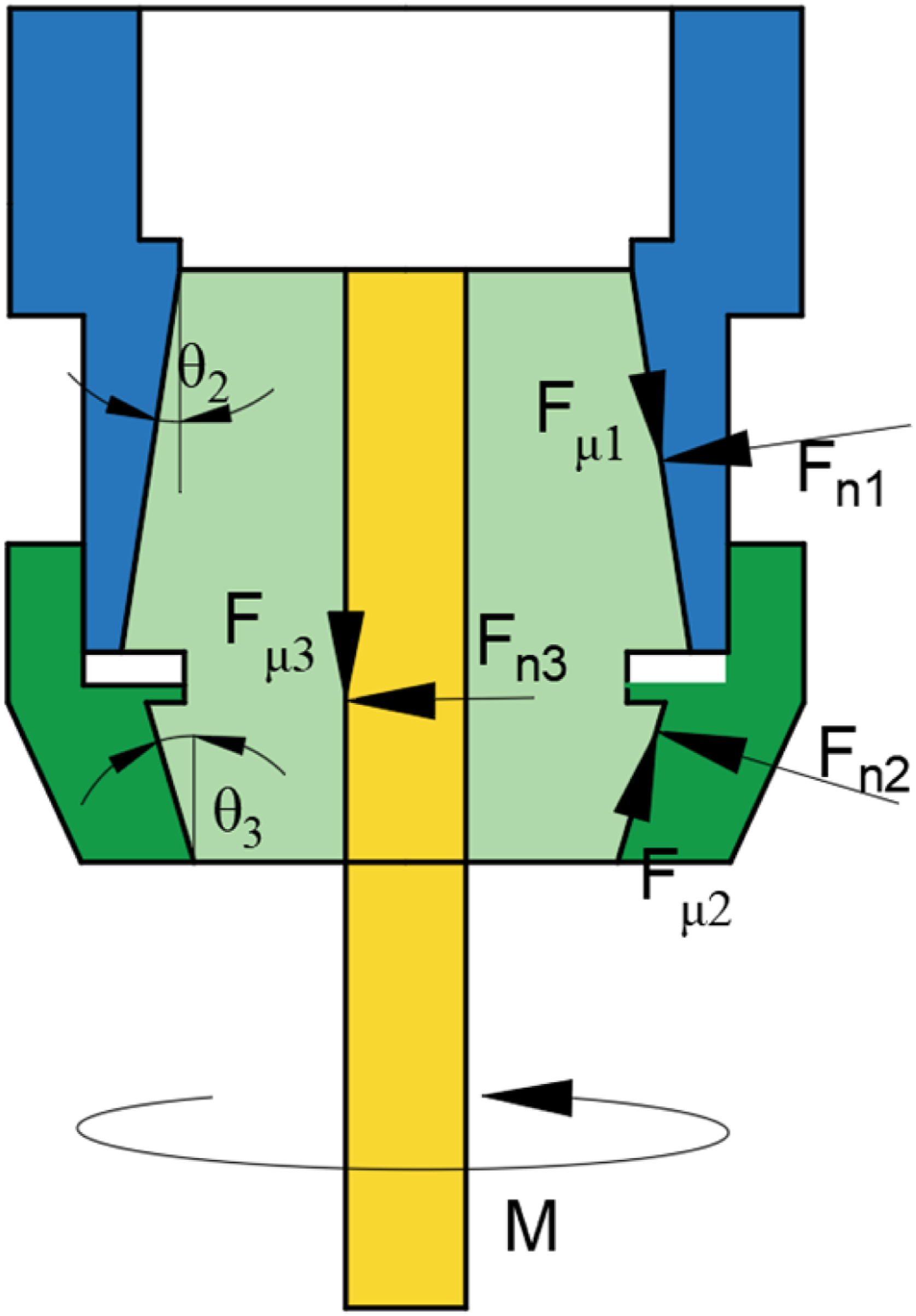
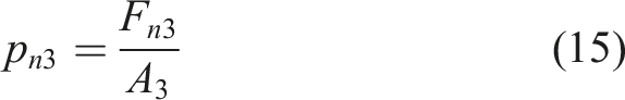
The expressions of each concentration force in Figure 7 are as follows:
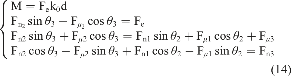
By solving equation (14), the positive pressure
2.3. Electromagnetic stiffness model of active magnetic bearing
This paper uses the equivalent magnetic circuit analysis method to model the electromagnetic force of the active magnetic bearing, and divides the radial magnetic bearing into four parts: stator yoke, magnetic pole, air gap, and rotor yoke, as shown in Figure 8: Structural diagram of active magnetic bearing.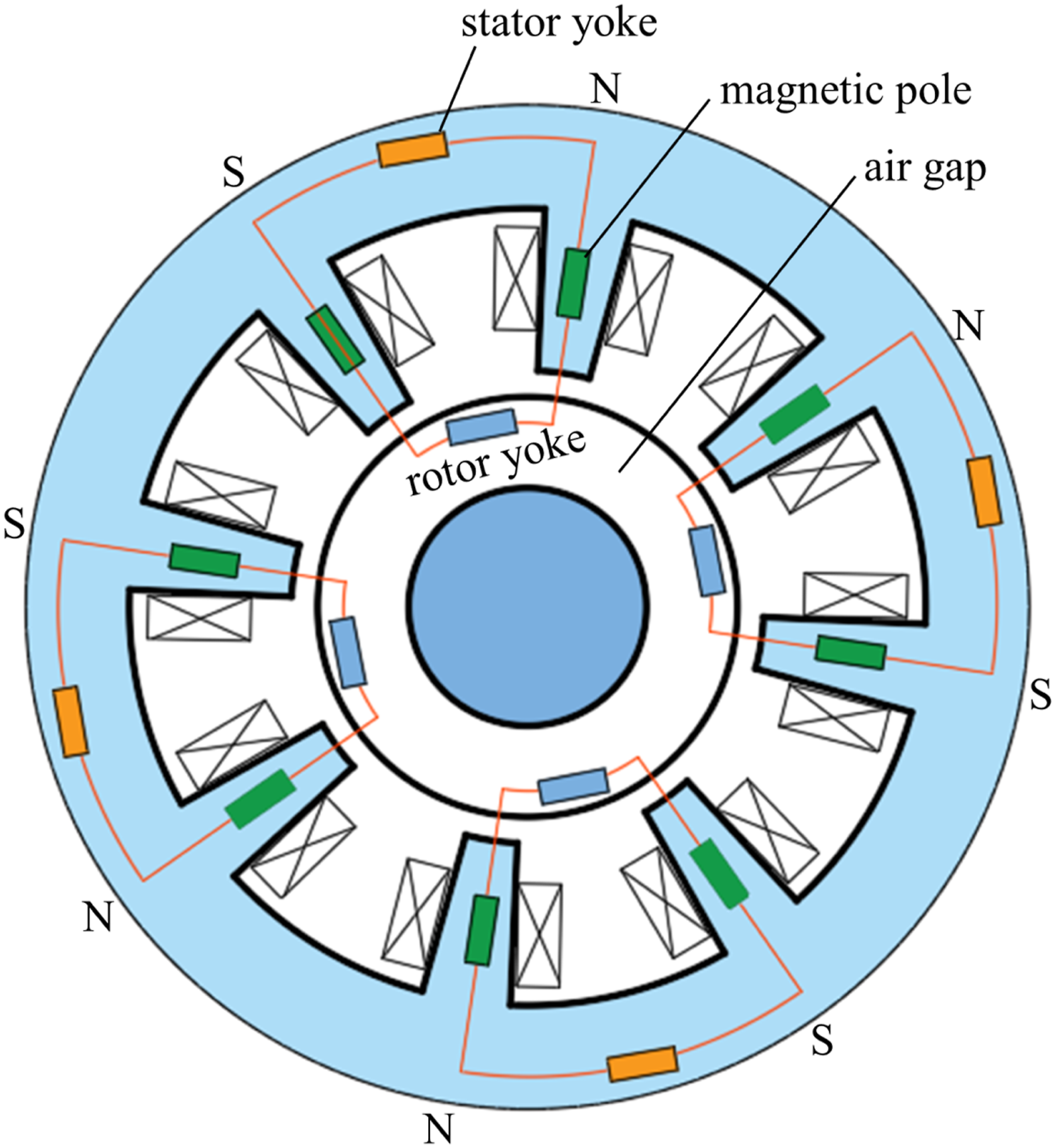
Based on the static suspension position of the rotor, during the high-speed rotation of the spindle, due to uneven mass distribution and external unbalanced excitation, the rotor’s spatial position shifts, as shown in Figure 9. Schematic diagram of rotor offset of magnetic bearing.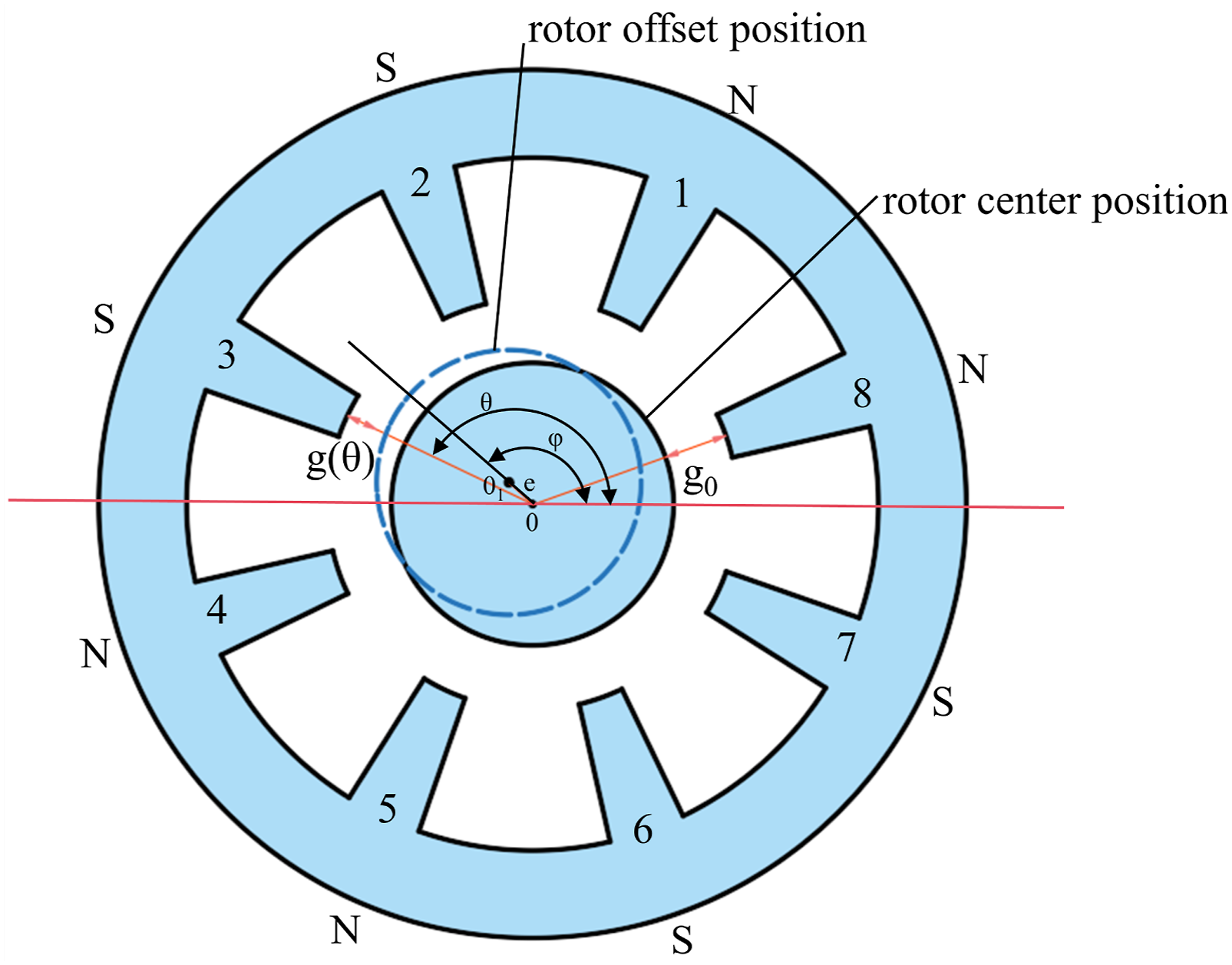
The offset of the rotor from the balance reference position is expressed by the eccentric angle

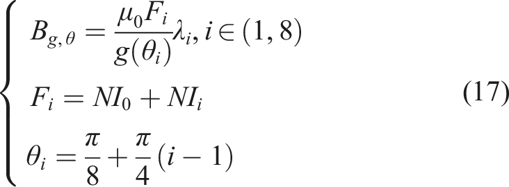
In order to obtain the total electromagnetic carrying capacity
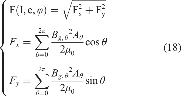
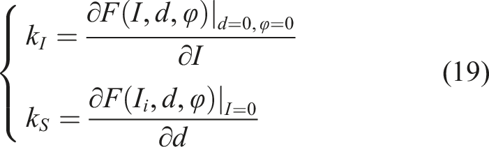
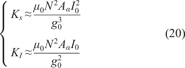
For different currents and rotor positions, the current stiffness
2.4. Milling force model
The magnetic levitation milling electric spindle will be affected by the milling force load during the cutting process. The milling force formula in the literature (Tang, 2014) is quoted here to decompose the milling force on the micro-element cutting edge into tangential milling force
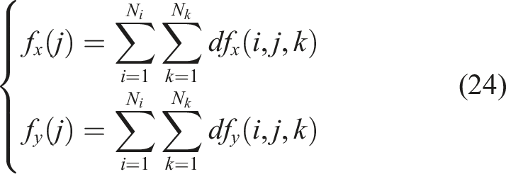
The total milling force component is obtained by summing the components of the milling force in the x and y directions of all micro-elements participating in the cutting:
3. Dynamic characteristic analysis
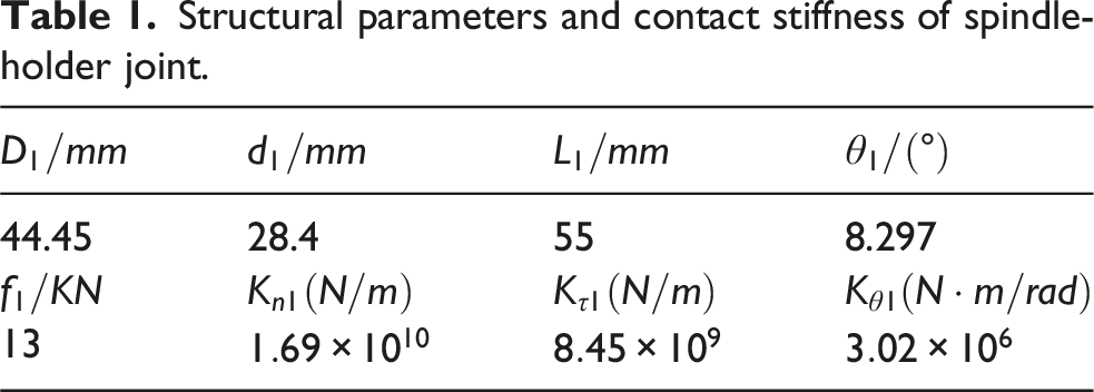
Structural parameters and contact stiffness of spindle-holder joint.
Structural parameters and contact stiffness of the holder-tool joint.
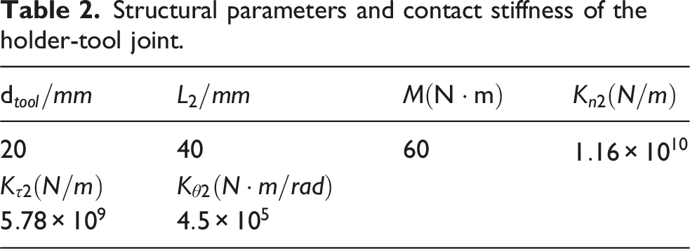
The data in Tables 1 and 2 are based on the structural parameters of the BT40 holder, which reference the international standard ISO 7388-2:2007(E). In the table:
Based on formulas (7) and (13), three sets of initial tool pulling forces are designated as the initial tool pulling forces. Simulation analysis reveals that with an increase in spindle speed, the contact stiffness and angular stiffness at the spindle-tool holder joint exhibit a notable decreasing trend, as illustrated in Figure 10. Stiffness variation diagram of the spindle-holder joint.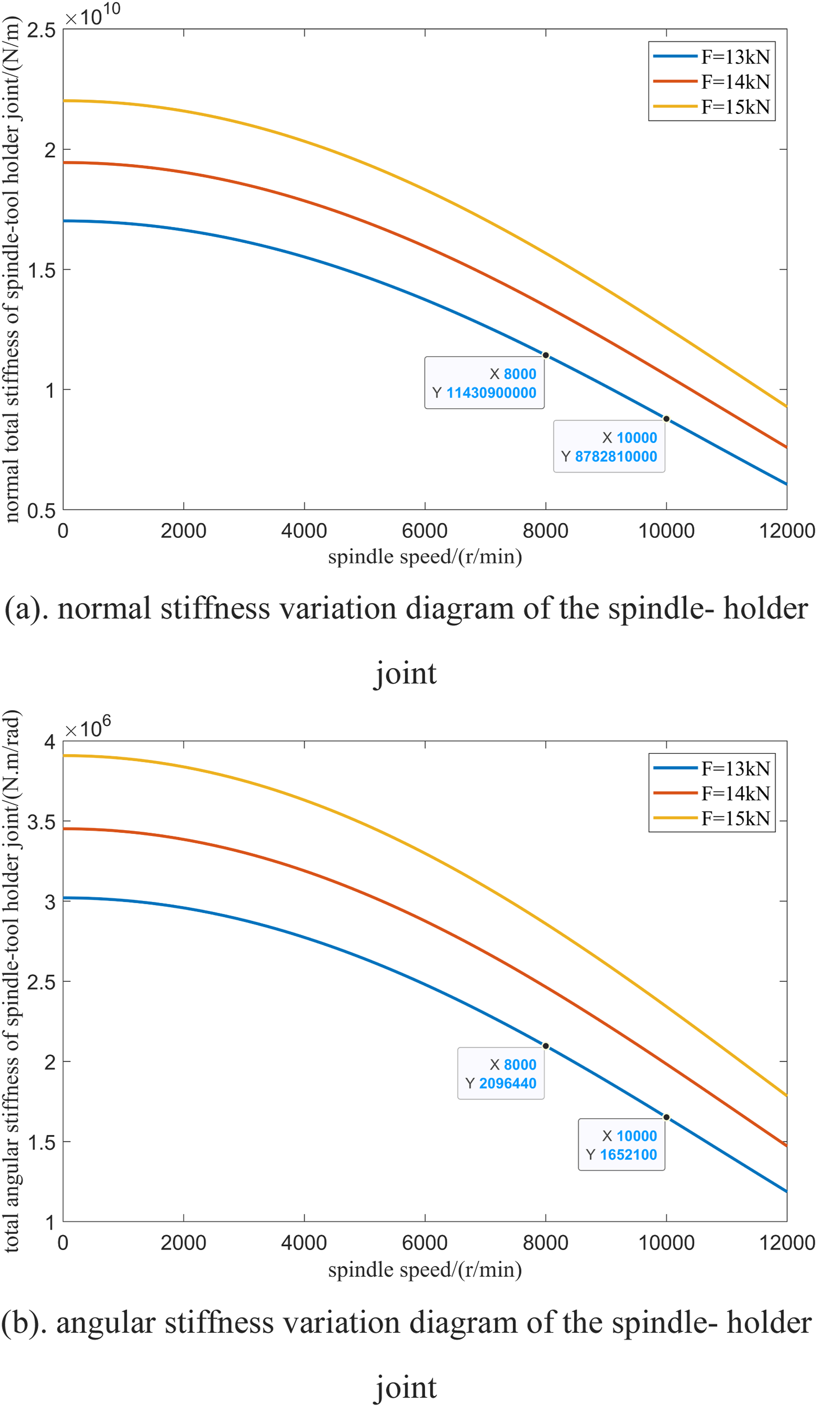
3.1. Modal analysis
Utilizing the dynamic model of the magnetic levitation milling electric spindle, which incorporates the spindle-holder-tool junction established previously, the first three natural modes of the system and their associated mode shapes were determined using MATLAB software, as illustrated in Figures 11–13. First-order modal shape diagram. Modal shape diagram (8000 r/min). Modal shape diagram (10,000 r/min).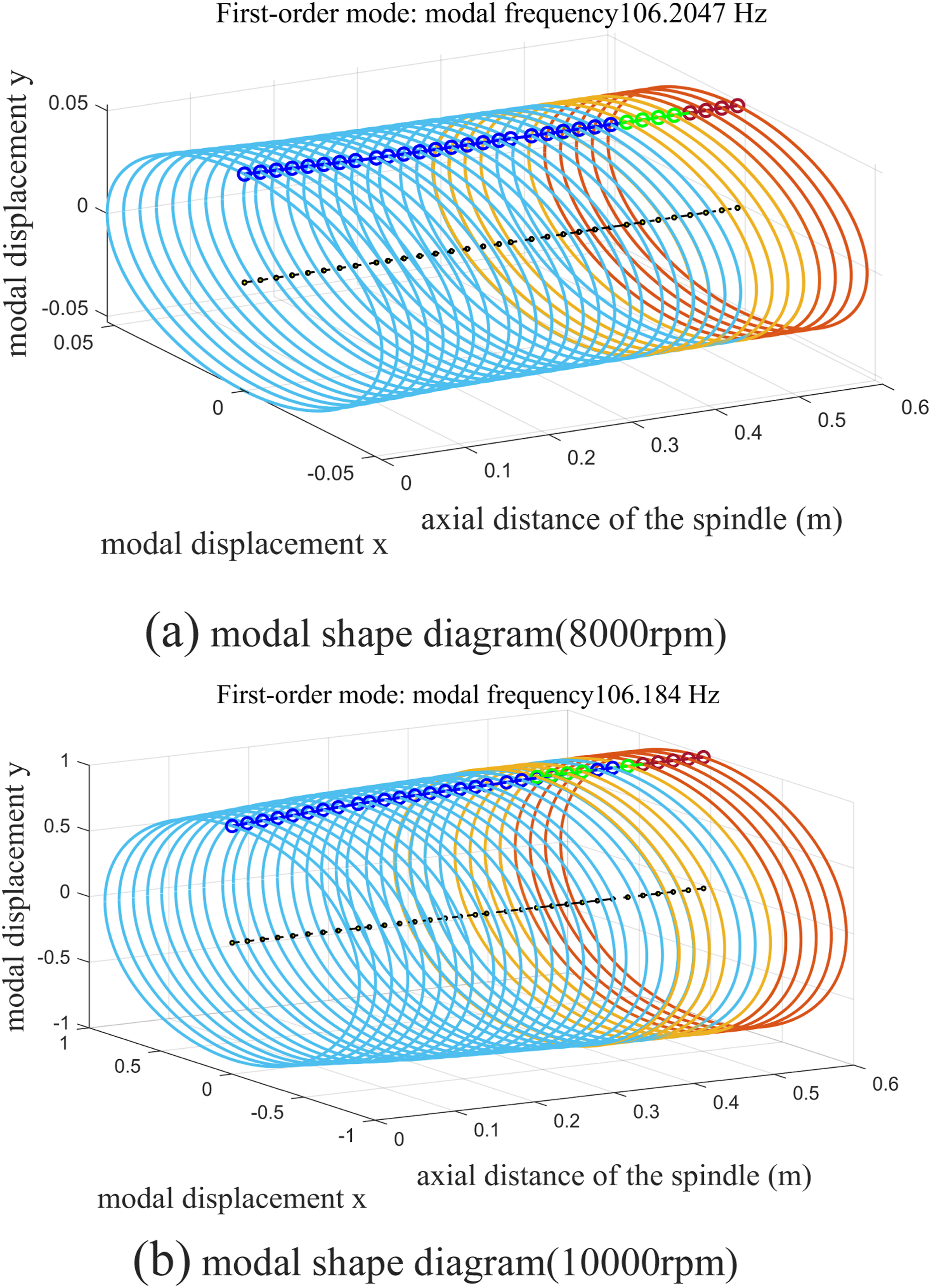
For the first-order mode, the system exhibits dominant rigid-body behavior, with a relatively uniform mode shape distribution along the structure. In this case, the deformation energy is minimal and not concentrated in the spindle-holder-tool joint region. As a result, the influence of joint stiffness variation on this mode is negligible. This is confirmed by the simulation results, where the first-order natural frequency shows only a slight change from
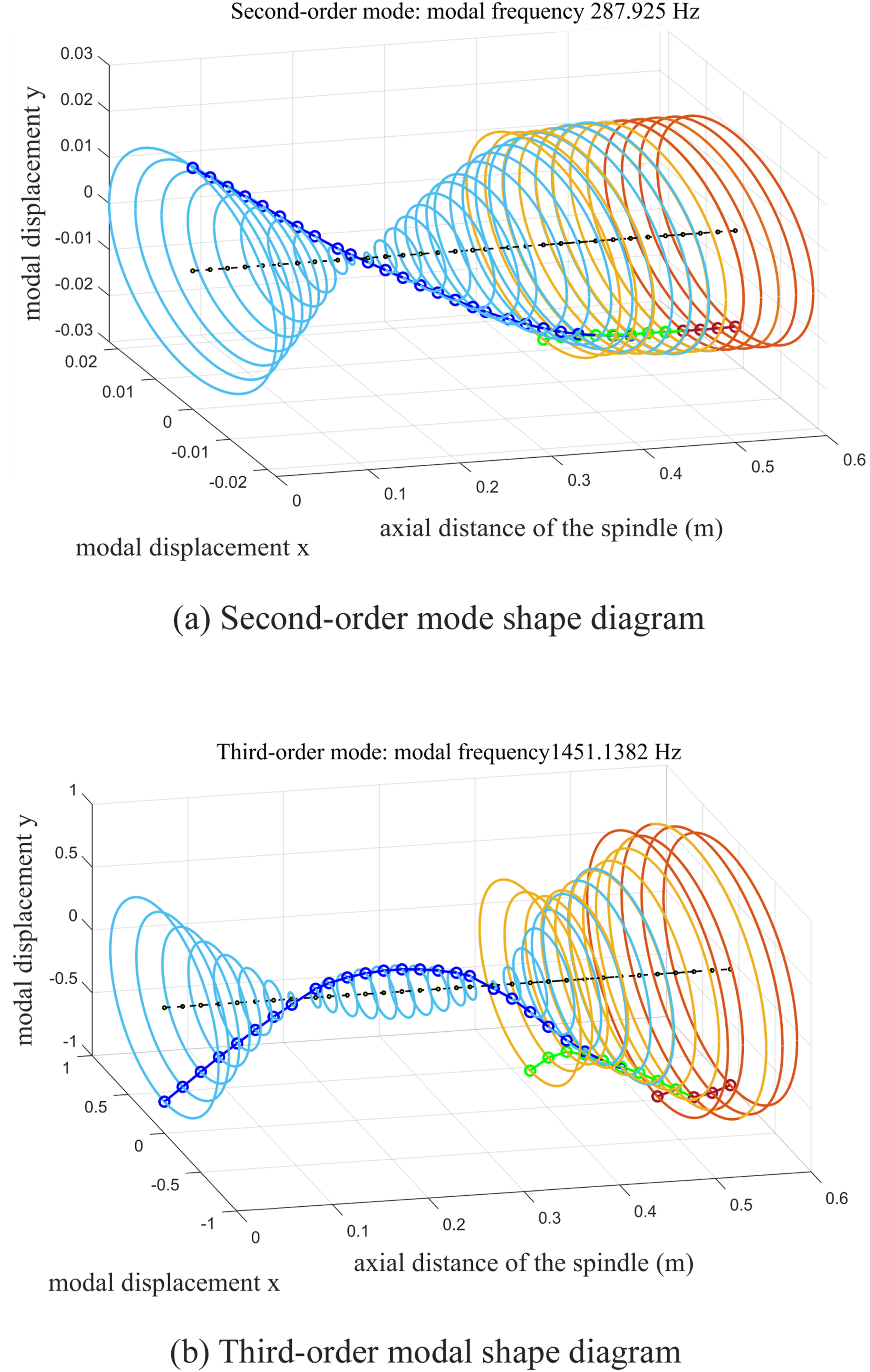
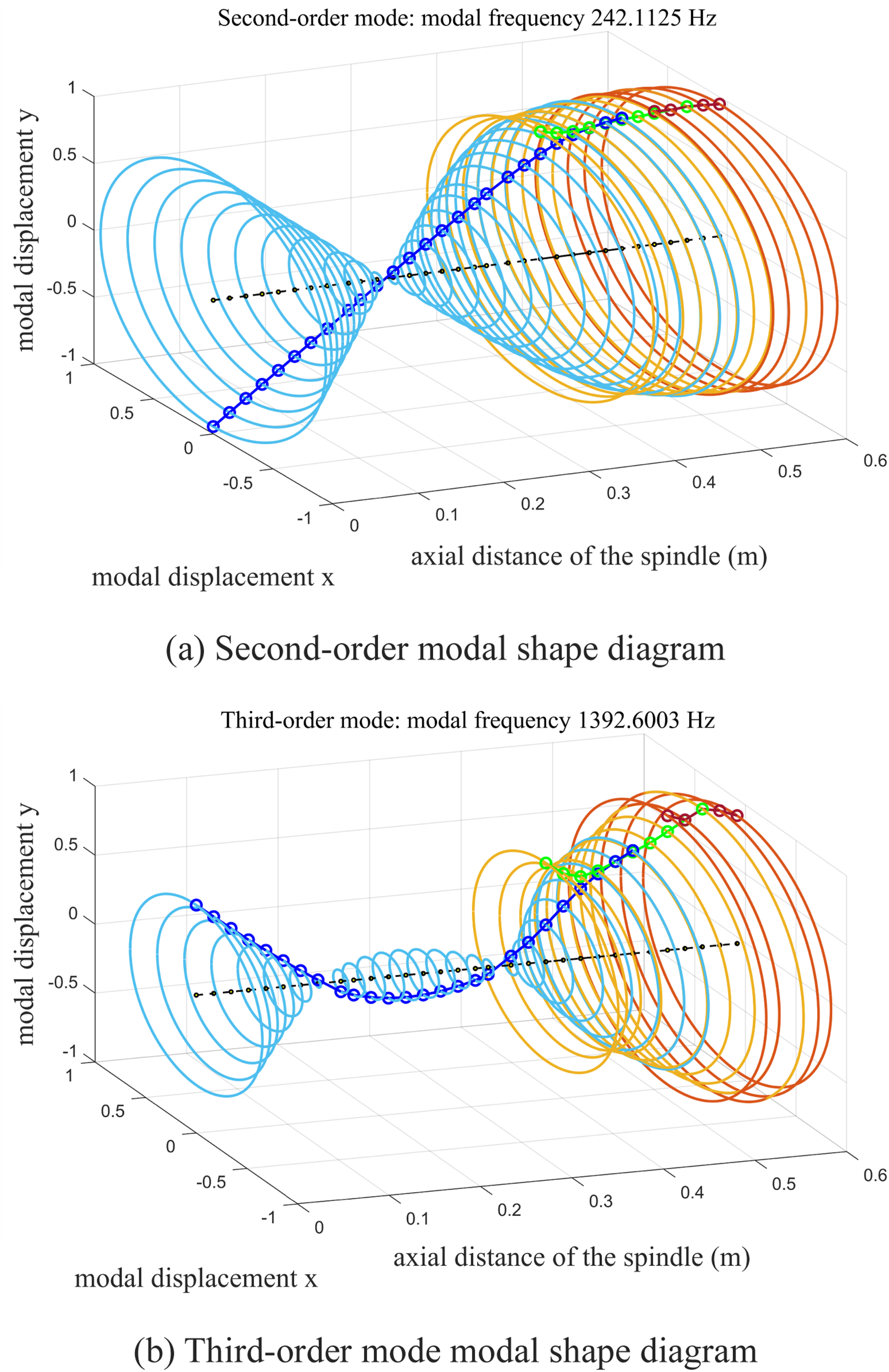
In contrast, the second-order mode is characterized by significant bending deformation, indicating the flexible dynamic behavior of the rotor system. Due to the abrupt change in cross-sectional geometry and moment of inertia between the spindle and the tool holder-tool assembly, a considerable portion of the modal strain energy is concentrated in the joint region. Consequently, the joint becomes a critical compliance location that strongly influences the modal characteristics. Under the effect of centrifugal expansion, the degradation of joint stiffness leads to a pronounced reduction in the second-order natural frequency, decreasing from
For the third-order mode, the deformation pattern becomes more complex, with multiple nodes appearing near the tool tip and the joint interface. In this higher-frequency range, the effects of shear deformation and rotary inertia, as described by Timoshenko beam theory, become more significant. However, the modal strain energy is distributed over a wider region of the structure, reducing the dominance of the joint region. As a result, the influence of local stiffness degradation is less pronounced, and the third-order natural frequency decreases from
These modal variations are closely related to the degradation of joint stiffness induced by centrifugal effects. Specifically, as the rotational speed increases from
3.2. Dynamic response analysis
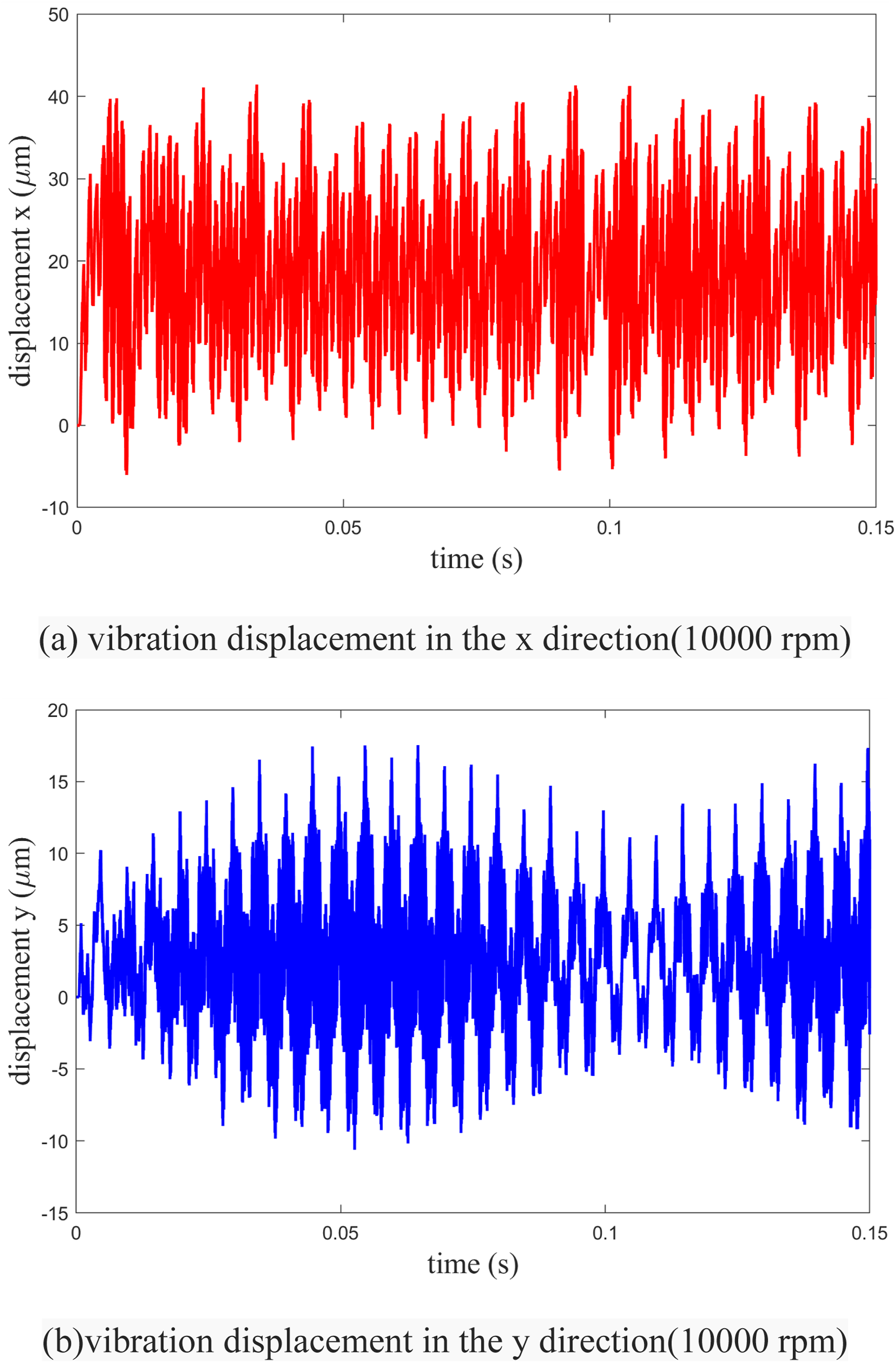
To elucidate the impact of variations in contact stiffness at the spindle-holder-tool junction on the dynamic behavior of the magnetic levitation milling electric spindle, the milling force was employed as the external excitation to determine the time-domain vibration response of the tool tip node across different rotational speed conditions. The vibration responses at the tool tip point are presented in Figures 14 and 15. Vibration response diagram of the tool tip (8000 r/min). Vibration response diagram of the tool tip (10,000 r/min).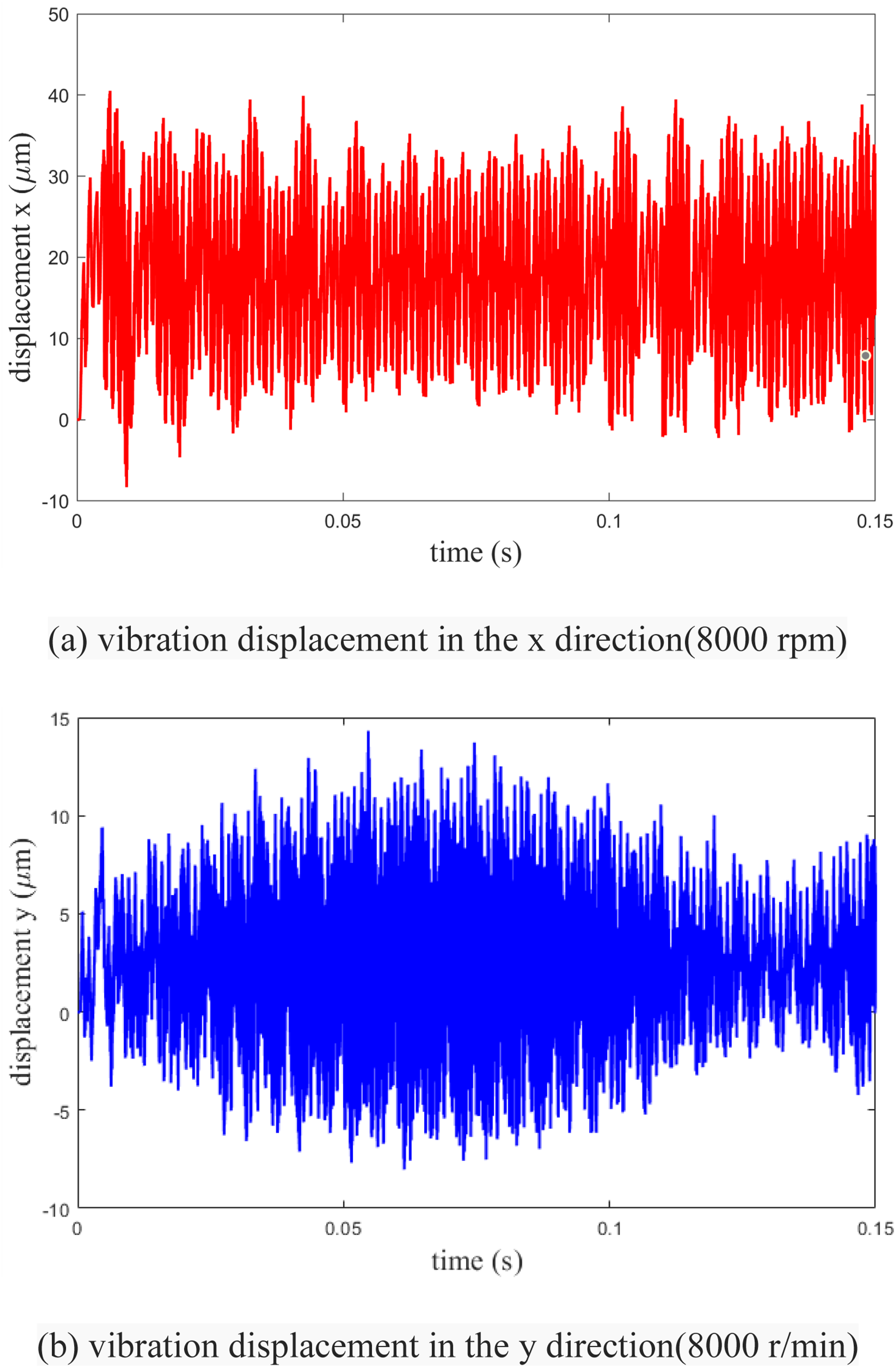
When the spindle speed is
When the spindle speed is increased to
4. Conclusion
In this paper, a dynamic model of a magnetic levitation milling spindle system considering the variable stiffness characteristics of the spindle-holder-tool joint was established. The effects of centrifugal expansion and rotational speed on joint stiffness and system dynamic response were systematically investigated. The results show that, as the rotational speed increases from
Furthermore, time-domain analysis indicates that the reduction in joint stiffness leads to a noticeable increase in tool tip vibration amplitude at higher rotational speeds. This demonstrates that joint stiffness plays a critical role in determining the dynamic stability of the spindle system.
The findings of this study provide important theoretical support for the design and optimization of high-speed magnetic levitation milling spindles. In particular, controlling joint stiffness and mitigating its degradation under centrifugal effects are essential for improving vibration performance and ensuring machining stability.
Footnotes
Funding
The authors disclosed receipt of the following financial support for the research, authorship, and/or publication of this article: This work was supported by the National Natural Science Foundation of China grant number 51875198, the Education Department of Hunan Province grant number 23A0360, and the Xiangtan Science and Technology Bureau grant number GX-YB20221004.
Declaration of conflicting interests
The authors declare that they have no known competing financial interests or personal relationships that could have appeared to influence the work reported in this paper.
Appendix
Simplifying equation (25), we can obtain:
The geometric equation is:
The physical equation is:
According to Hooke’s Law, it can be obtained that:
The boundary conditions can be obtained from Figure 16.
In the formula: Schematic diagram of the taper hole fit between the spindle and the holder.