
Abstract
To address the challenge of low-frequency vibration isolation, this study proposes a novel bionic quasi-zero-stiffness (QZS) isolator inspired by the load-bearing capacity and stability of turtle limbs. The bionic turtle limb structure (BTLS) employs rigid rods and linear springs to mimic the femur–tibia configuration and replicate the negative stiffness of muscles and tendons. By integrating BTLS with a positive-stiffness parallel mechanism, QZS characteristics are achieved. A nonlinear mechanical model is developed through static analysis and parametric investigation. The theoretical model is validated using ADAMS simulations, demonstrating that the proposed isolator enhances load capacity by 46.02% and broadens the isolation bandwidth by 30% relative to a conventional three-spring QZS isolator. Dynamic analysis based on Newton–Euler equations and the harmonic balance method yields amplitude– and phase–frequency responses. Experiments confirm improved low-frequency isolation, with a 45.86% reduction in initial isolation frequency relative to a linear isolator. This work innovatively applies turtle limb biomechanics to QZS design, demonstrating high load capacity, broadband isolation, and enhanced low-frequency performance.
Keywords
1. Introduction
Vibration presents a critical threat to equipment service life, precision instrument performance, and operational reliability, while also endangering human health (Liu et al., 2015). Conventional linear spring–mass–damper isolators effectively attenuate medium-to-high frequency excitations, particularly above √2 times the system natural frequency (Ji et al., 2021). However, reducing stiffness to widen the isolation bandwidth inevitably causes excessive static deformation (Yang et al., 2021), whereas increasing mass imposes economic and practical constraints (Yan et al., 2021). To overcome the inherent trade-off between load capacity and isolation bandwidth, quasi-zero-stiffness (QZS) isolators, characterized by high static stiffness and low dynamic stiffness, have attracted considerable research interest (Araki et al., 2013). Beyond vibration isolation, QZS characteristics have also demonstrated potential in energy harvesting applications, where the high-static-low-dynamic stiffness property enables efficient energy conversion under low-frequency excitation (Jiang et al., 2025).
The three-spring QZS configuration was first introduced by Carrella et al. (2007). Further extending, Jiang et al. (2020) developed a spatial three-spring QZS structure by substituting the original oblique and vertical springs with electromagnetic and air springs, respectively. Suman et al. (2021) replaced the vertical spring with an air spring and applied the resulting QZS vibration isolation system to an automotive suspension. According to the parallel configuration principle, QZS isolators typically integrate positive and negative stiffness elements (Zhou et al., 2021). Negative stiffness can be achieved through various nonlinear mechanisms, including geometric structures such as multi-link mechanisms (Dai et al., 2025) and inclined springs (Wang et al., 2020), material properties like magnetic structures (Yu et al., 2025b) and TPU (Zheng et al., 2023), or intrinsic nonlinearity of components such as disc springs (Zhou et al., 2019) and kirigami structures (Yu et al., 2025a). Conversely, positive stiffness is generally provided by linear (Chai et al., 2023) or variable-stiffness elements (Yan et al., 2022). In addition to rigid-link mechanisms, compliant mechanisms have emerged as an effective approach for realizing QZS characteristics. For instance, bistable compliant beams can generate negative stiffness, and QZS behavior can be achieved through serial or parallel combinations of compliant beams (Ding et al., 2023). Despite the variety of implementation methods, the QZS region in many configurations remains narrow, motivating extensive efforts to extend the effective isolation range.
Inspired by biological systems that have evolved highly efficient load-bearing and vibration-attenuation strategies over millions of years, researchers have increasingly adopted bionic principles to develop novel mechanical structures tailored to specific operational environments (Bosia et al., 2022). Numerous bionic vibration isolators have been developed based on structures ranging from human limbs to animal musculoskeletal systems (Trinh et al., 2024). However, reptile skeletal structures remain relatively underexplored. For example, X-shaped QZS structures inspired by animal limb configurations have shown significant low-frequency vibration isolation performance (Jing et al., 2022). Similarly, avian knee joints (Sun et al., 2022), feline skeletal deformation during landing (Yan et al., 2020), and insect exoskeletons (Ling et al., 2023) have inspired various rod-spring biomimetic models. Despite these advances, significant opportunities remain for innovation in bionic structures (Wang et al., 2019). Turtles, through evolutionary adaptation, possess a unique limb compression system that provides exceptional load-bearing capacity and stability under low-frequency vibrations. The carapace and internal tissues account for most of the turtle’s body mass, yet the animal maintains stability even under additional external loading. In their natural habitat, turtles primarily perceive and respond to low-frequency vibrations below 20 Hz (Rosenberg, 1986), exhibiting notable resistance to vibrational disturbances during slow locomotion over uneven terrain. This stability is primarily attributed to the interaction between the femur–tibia structure and the muscle-tendon system of the limbs, which effectively absorbs and dissipates mechanical vibrations in low-frequency environments.
In summary, rod-spring bionic models simulating bone-muscle systems have become widely accepted among researchers. However, substantial opportunities remain for bionic structure innovation. Through biological evolution, turtles have developed a unique limb compression system that provides excellent load-bearing capacity and stability under low-frequency vibrations. Drawing on these biomechanical characteristics, this study proposes a bionic turtle limb structure (BTLS) composed of rigid rods and linear springs. The BTLS enables tunable QZS behavior under heavy load conditions through adjustment of its structural parameters. The remainder of this paper is structured as follows. Section 2 presents the abstraction of the bionic turtle limb model into a physical model and analyzes its geometric and static characteristics. Section 3 develops and analyzes the dynamic model of the BTLS isolation system, deriving the amplitude-frequency response and displacement transmissibility while conducting a parametric study on isolation performance. Section 4 validates the proposed low-frequency isolator through ADAMS dynamic simulations and experimental tests. Section 5 concludes the study.
2. Static analysis
2.1. BTLS with linear negative stiffness
Although turtles display relatively slow locomotion in nature, their exceptional stability and load-bearing capacity enable them to maintain balance under self-weight loading. This exceptional low-frequency vibration isolation capability can be attributed precisely to the unique skeletal-musculature architecture of their limbs. Figure 1 illustrates a schematic of the turtle limb. The femur and tibia in the turtle limb correspond functionally to the human femur and the composite structure of the fibula and tibia, serving a comparable role in limb articulation and support. Under load, the rotation at the femur-tibia joint, resembling human knee-flexion motion, attenuates vibrations. Surrounding muscles and tendons provide essential support and elasticity. To mimic the tunable stiffness characteristic inherent to the turtle limb, we model this biological system using rigid links representing the femur and tibia, coupled with linear springs representing the muscles, tendons, and other connective tissues between these bones. This configuration forms part of the negative stiffness component of the proposed turtle-inspired isolator. The Schematic diagram of the BTLS.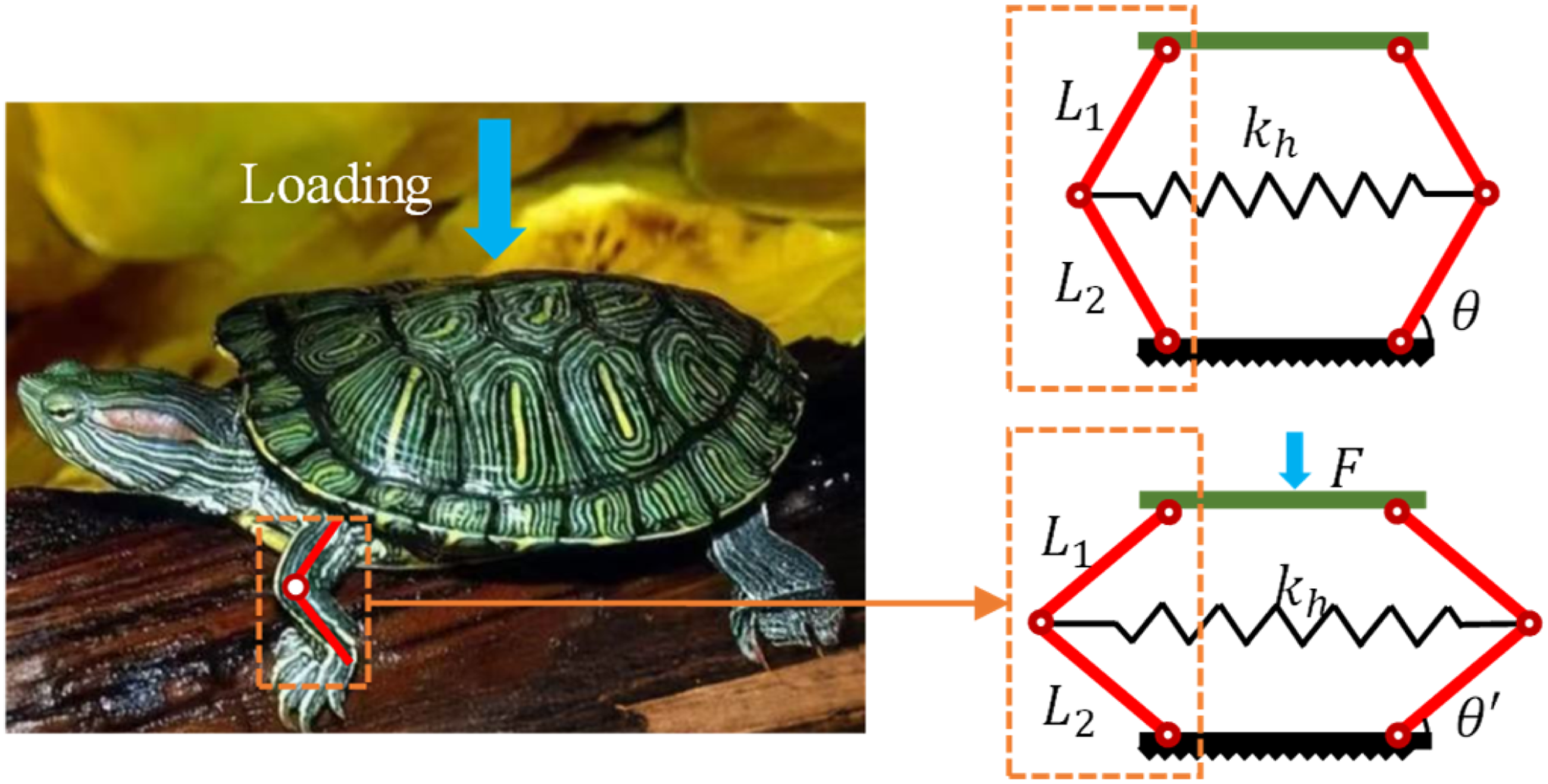
Drawing inspiration from the structural features of turtle limbs, a bio-inspired vibration isolator is designed. This configuration abstracts the turtle’s shell and the internal organs above the limb into a single isolator, facilitating the mounting of equipment to be isolated. The joint between the femur and the tortoise body, the joint between the tibia and the femur, and the joint between the tibia and the ground were connected by revolute joints. The horizontal linear spring connects the tibia-femur joints across the anterior and posterior limbs, serving to inhibit outward movement at the knee joint. In this paper, the length of femur and tibia is designed as
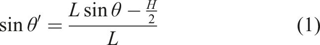
The static equilibrium position diagram for the vibration isolator under static load is shown in Figure 1. Based on the geometric configuration, the upper platform undergoes a vertical downward displacement


Based on the linear spring force
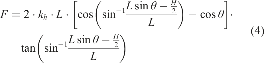
The equivalent stiffness
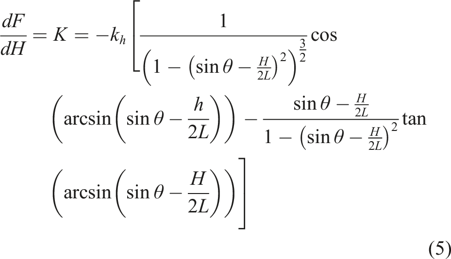
Equation (5) indicates that the static restoring force of the vibration isolator is influenced by the linear spring stiffness Static characteristic diagram under different parameters.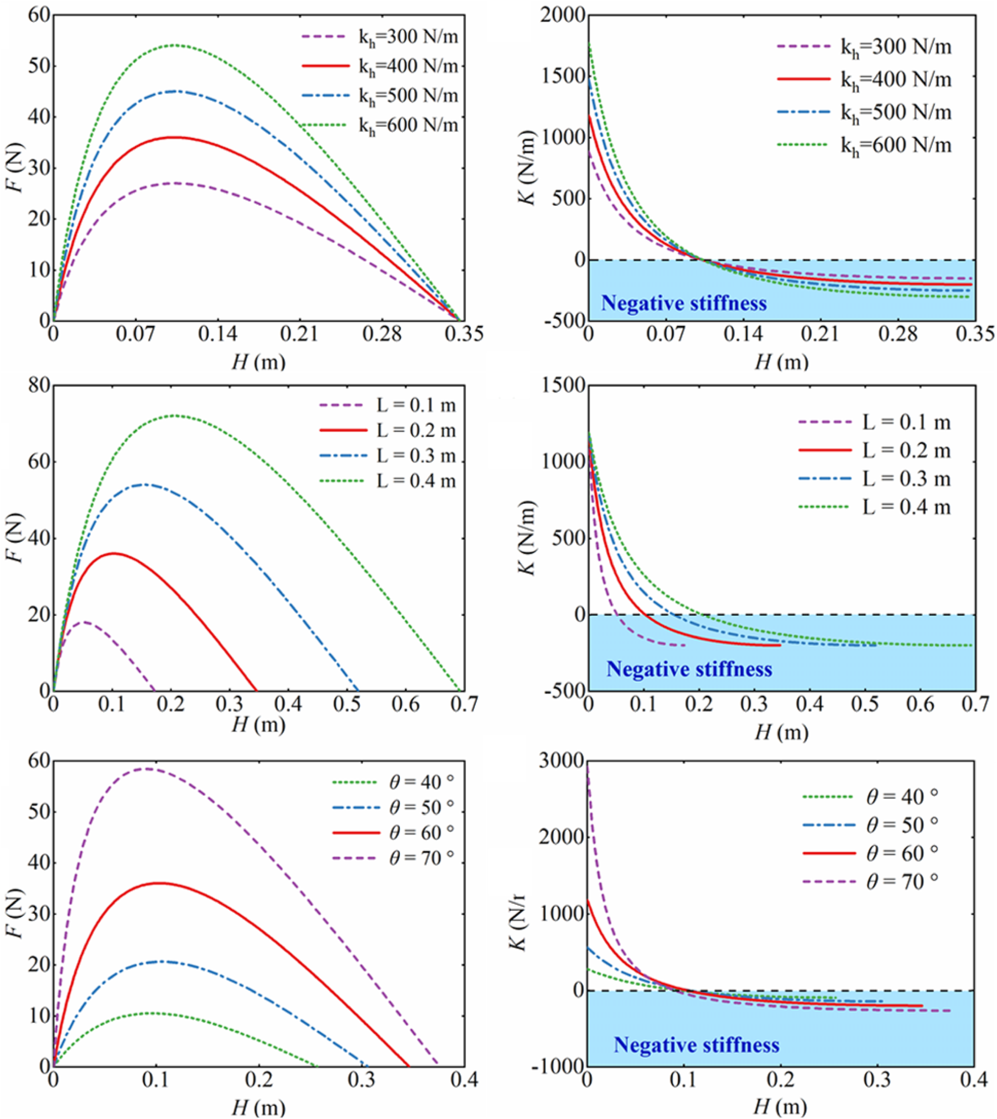
As shown in Figure 2, the slopes of these curves correspond to positive, zero, and negative stiffness regimes during compression, as respectively indicated. Initially, the force
Figure 2 further illustrates the influences of rod length
2.2. Design of BTLS-QZS vibration isolator
Based on section 2.1, the BTLS has good stiffness adjustability and the negative stiffness is nearly linear. To compensate for its inherent drawbacks such as instability and reduced load-bearing capacity, the negative stiffness system is integrated with positive stiffness elements in a parallel configuration. By integrating the positive stiffness of a traditional linear spring and the negative stiffness of the BTLS in a parallel arrangement, a quasi-zero stiffness state is realized. This constitutes a quasi-zero stiffness isolation system that offers improved performance for low-frequency isolation.
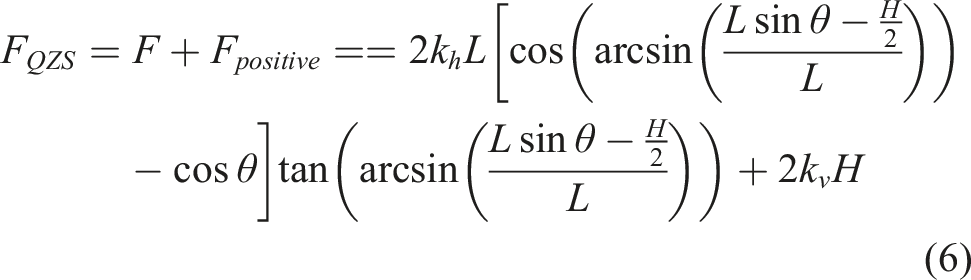
A linear positive-stiffness spring is employed as a compensating element, connected in parallel with the BTLS to achieve QZS. Specifically, a linear vertical spring links the articulation point among the isolator, base, and connecting rod. The QZS system restoring force expression can be further derived a
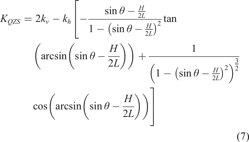
Taking the derivative of equation (6) yields the expression for the equivalent stiffness Static characteristic curve of the BTLS-QZS isolator.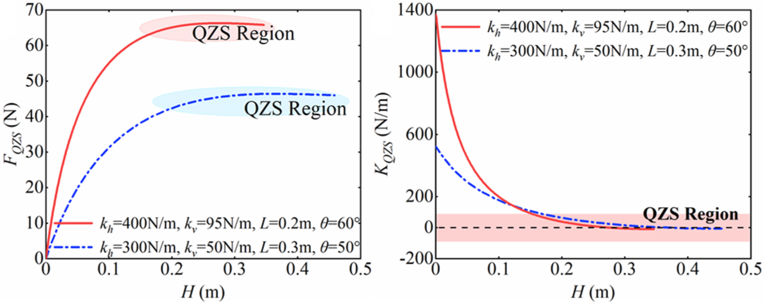
2.3. Verification and high bearing capacity designing
To validate the theoretical analysis and numerical calculations for the BTLS-QZS, a multi-body dynamics simulation was conducted using ADAMS. As shown in Figure 4, the restoring force curves derived theoretically for both QZS configurations exhibit close agreement with the simulation results, which confirms the correctness of the presented analytical methodology and computational procedures. (a) The multi-body dynamics model of the BTLS-QZS isolator; (b) comparison of simulated and theoretical restoring force-displacement curves.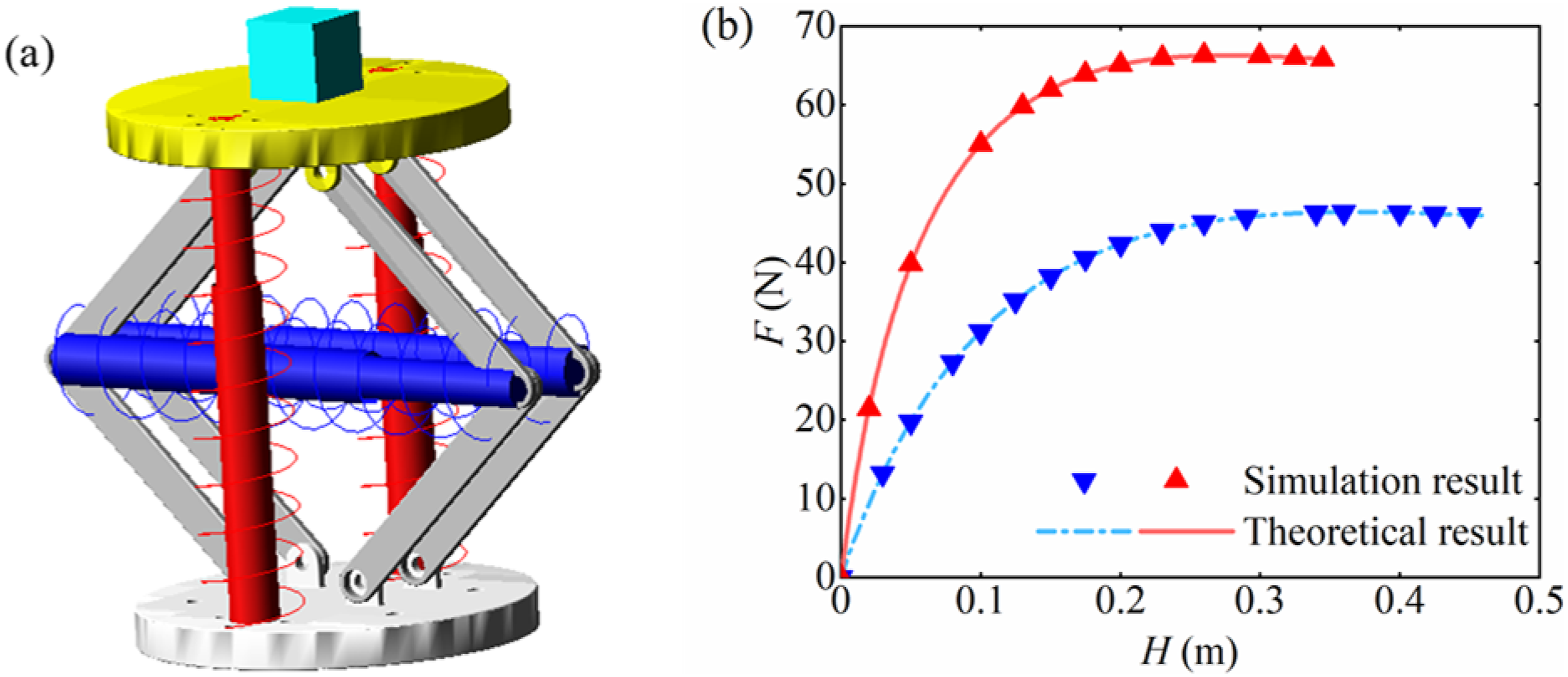
The above study proved that the BTLS-QZS vibration isolator has good quasi-zero stiffness characteristics through theoretical analysis and simulation verification. Once the design parameters of the BTLS are specified, a BTLS-QZS system can be configured by tuning the stiffness of the vertical spring compensation mechanism. The resulting isolator exhibits an extended operational stroke and enhanced load capacity. Furthermore, the parameters of the BTLS remain adjustable to meet vibration isolation requirements across varying load conditions.
To benchmark the high load-bearing capacity, the restoring force and equivalent stiffness of the proposed BTLS-QZS are compared with the classical three-spring QZS isolator, as shown in Figure 5. The total stroke and positive stiffness compensation were adjusted to be the same for fairness. This is because the positive stiffness spring provides the main support force when the isolator is in the QZS zone. The mechanical characteristic curves of the BTLS-QZS and the three-spring QZS are shown in Figure 5 respectively, under the conditions of the total stroke Comparison of static characteristics of (a) the BTLS-QZS and (b) three-springs QZS.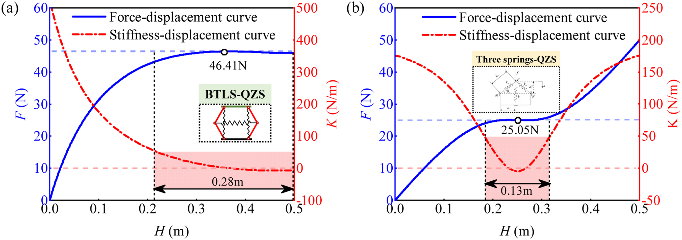
3. Dynamic analysis
3.1. Dynamic modeling
The energy of this vibration isolation system is mainly consumed by the spring, air, and damper provided by their self-damping and the friction between the components. Neglecting nonlinear damping effects in this section, the above damping is equivalent to a controllable viscous damper
This section investigates the dynamic response of the BTLS-QZS under harmonic base displacement excitation, with the system dynamics governed by equation (8)

By defining the relative displacement between the BTLS-QZS and the base as


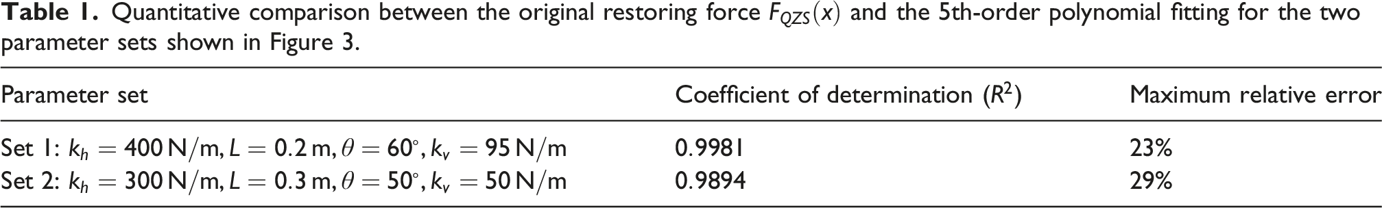
Quantitative comparison between the original restoring force
Subsequently, substituting equation (10) into equation (9) yields the nonlinear kinetic equation.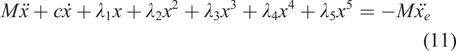


Substitution of the harmonic excitation 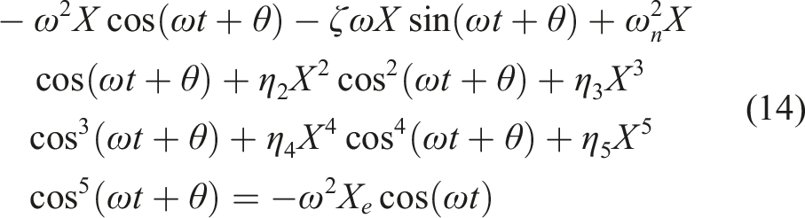
By applying trigonometric identities to expand the expressions, neglecting higher-order harmonics, and equating the coefficients of corresponding harmonic terms, the following relation is obtained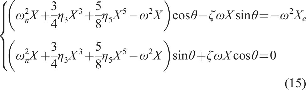
The amplitude-frequency and phase-frequency response equations is obtained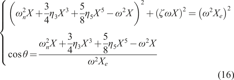
For a prescribed excitation frequency 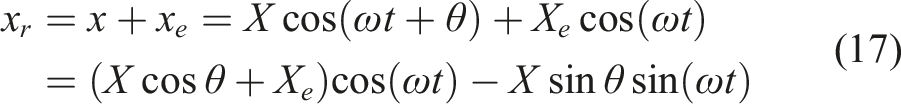
Accordingly, the displacement transmissibility rate can be quantified using the equation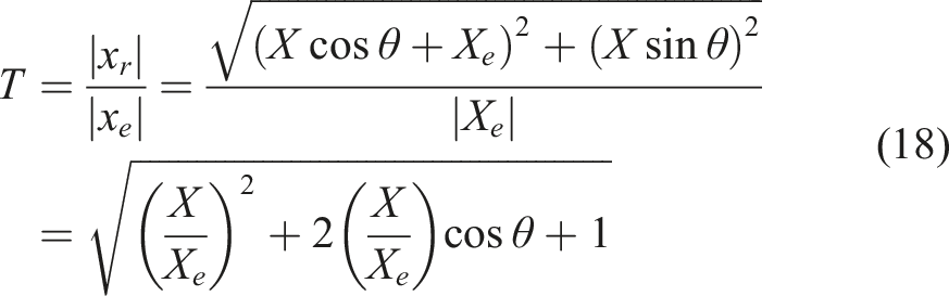
3.2. Vibration isolation performance
This section evaluates the low-frequency vibration isolation performance of the BTLS-QZS. In order to verify the accuracy of the analysis results, the corresponding numerical analysis is first carried out in Figure 6. The numerical results are obtained by using both forward and backward frequency sweeps in the Runge-Kutta scheme. In Figure 6, the black solid line represents the analysis results of the response, and the red hollow circle represents the numerical results. The results show that the numerical calculation results are in good agreement with the analysis results in the whole frequency band. Notably, numerical solutions within the resonance interval fail to be acquired by Runge-Kutta numerical integration. Amplitude-frequency response and discussion results of displacement transmissibility of different parameters.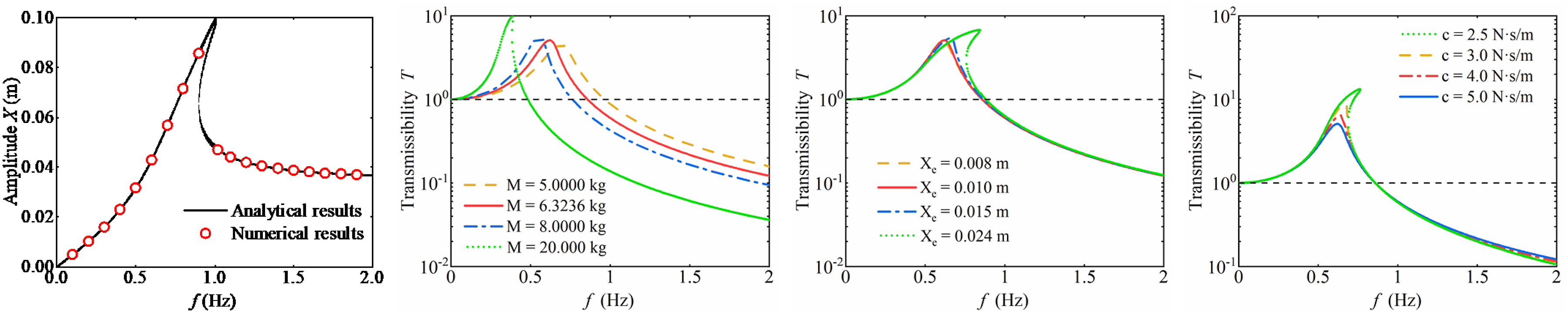
The assessment employs the theoretical framework from Section 3.1, using the initial isolation frequency, resonance peak and peak transmissibility as the primary metrics, and examines the influence of key parameters including load mass
Figure 6 illustrates the displacement transmissibility of the BTLS-QZS under different parameters. The parameter ranges for the parametric study in Figure 6 are selected based on both practical engineering constraints and the operational limits of the proposed isolator. Specifically, the mass range of 0∼20 kg covers from the unloaded condition to approximately 3.2 times the rated load (6.32 kg), allowing observation of the system’s behavior from linear to strongly nonlinear and stiffness-hardening regimes. The excitation amplitude range of 0.008∼0.024 m is chosen to span from small-amplitude vibrations, where the system behaves nearly linearly, to larger amplitudes that induce the nonlinear geometric stiffness, ensuring the system remains within its maximum allowable stroke
Increasing
An increase in
The resonance peak decreases with increasing
Furthermore, the effects of nonlinear term coefficients on the isolation performance are examined. While the fifth-order coefficient is found to have negligible influence and is thus omitted from graphical representation, the impacts of the first-order and third-order coefficients on displacement transmissibility are detailed in Figure 7. As described in Section 3.1, these coefficients are derived from fitting the static force-displacement relation in equation (6). Consequently, given that the influence of these terms is fundamentally linked to the static design, the analysis herein is focused on a qualitative assessment of their effect on the system’s transmissibility. Effect of nonlinear term coefficients 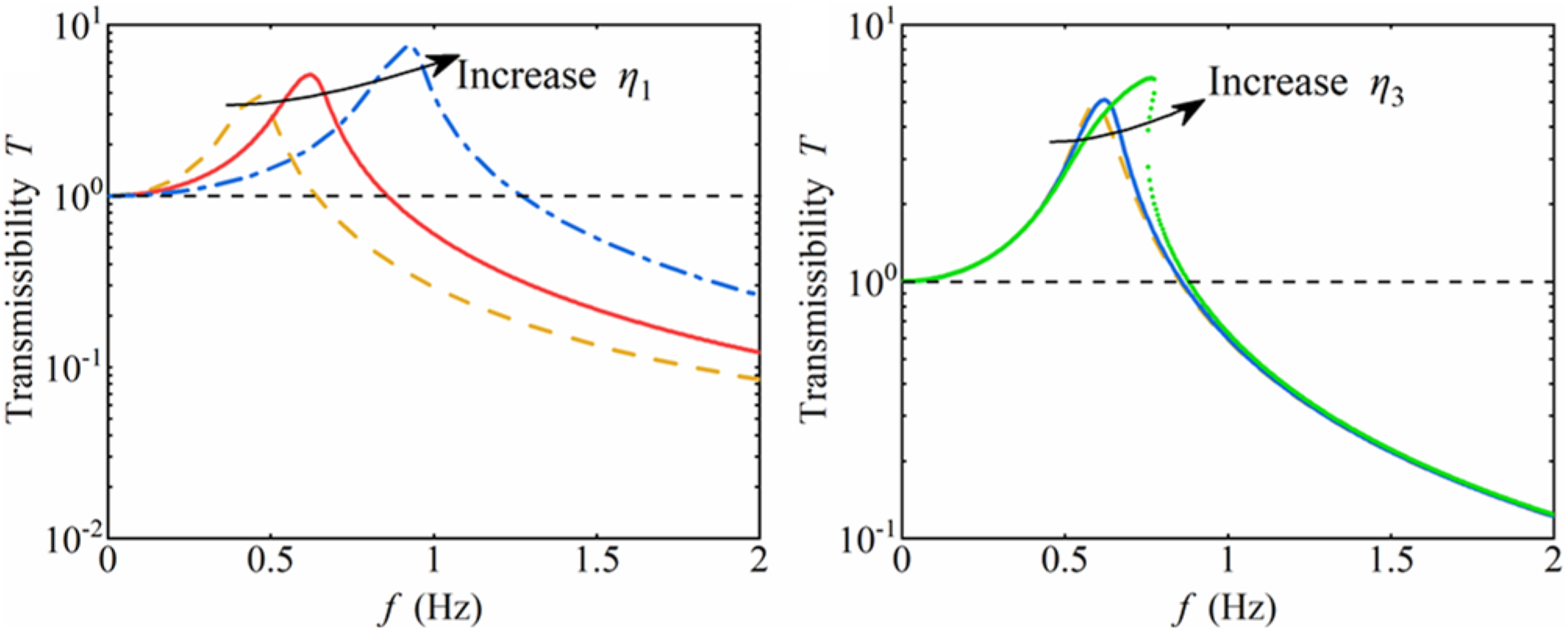
Figure 7 illustrates the influence of the first-order nonlinear coefficient
3.3. Comparison of low frequency vibration isolation performance
To benchmark the superior vibration isolation performance of the proposed BTLS-QZS, a comparative analysis with a conventional linear isolator is conducted under controlled conditions. The comparison ensures a single variable between the two systems: the stiffness of the linear isolator is set equal to the positive stiffness value of the BTLS-QZS. Figure 8 compares the time-domain response of the BTLS-QZS isolator and the linear isolation system at 0.5 Hz, 1 Hz, 2 Hz, and 3 Hz, respectively. Excitation and response of the BTLS-QZS isolator and the linear isolator at different excitation frequencies.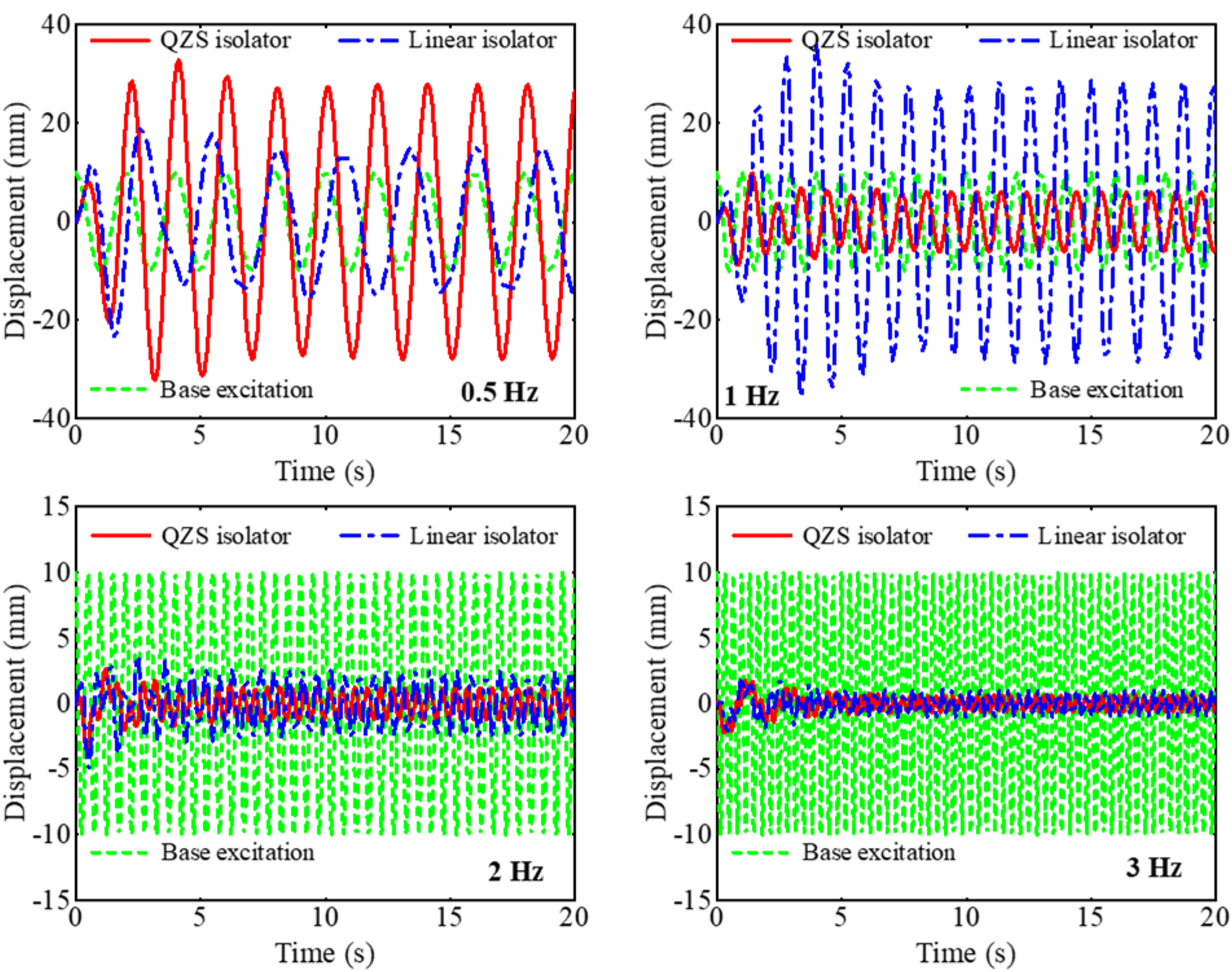
Initially, at an excitation frequency of 0.5 Hz, neither system achieves isolation, as their response amplitudes exceed the input amplitude. At 1 Hz, the BTLS-QZS exhibits a response amplitude lower than the excitation, indicating it has entered the isolation regime, whereas the linear system remains within its resonant zone. At higher frequencies, both systems operate in isolation.
The BTLS-QZS demonstrates an initial isolation frequency in 0.5∼1 Hz, compared to 1∼2 Hz for the linear system, a finding consistent with the numerical simulations in Figure 9. It is further observed that within the isolation band, the displacement amplitude of the BTLS-QZS continues to diminish with increasing frequency, enhancing its isolation effectiveness. In summary, the BTLS-QZS not only features a low resonance peak in the low-frequency range but also maintains superior isolation performance into the mid and high frequency ranges, thereby substantially broadening the effective isolation bandwidth of the system. Displacement transmissibility rate 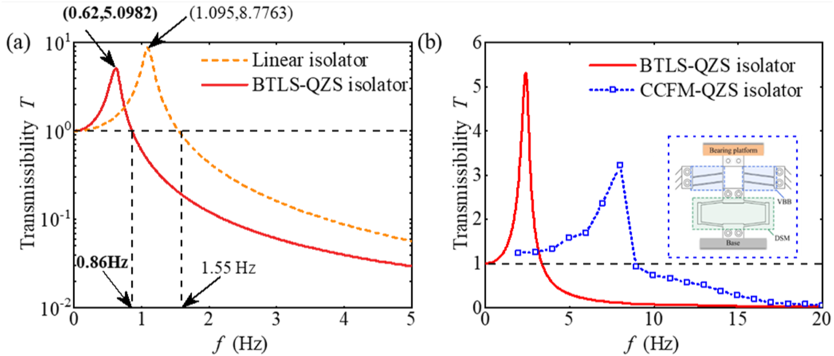
Figure 9 compares the displacement transmissibility of the three isolators. The BTLS-QZS reaches its resonance at 0.62 Hz with a peak transmissibility of 5.10, whereas the linear system resonates at a higher frequency of 1.10 Hz with a peak of 8.78. It represents a reduction of approximately 41.91% in peak transmissibility. Furthermore, the initial isolation frequency of the BTLS-QZS is 0.86 Hz, which is 44.50% lower than that of the linear isolator, indicating a substantially extended effective isolation bandwidth.
To further highlight the low-frequency vibration isolation capability of the proposed BTLS-QZS isolator, a direct comparison was conducted against the CCFM-QZS isolator reported in (Li et al., 2024) under identical loading conditions (mass = 6 kg). The specific parameters for the proposed isolator were set as
4. Verification
4.1. ADAMS simulation analysis
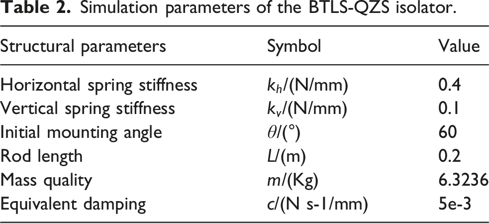
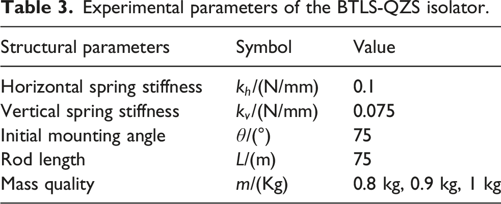
Simulation parameters of the BTLS-QZS isolator.
A swept-sine excitation in the Y-direction was applied to both the BTLS-QZS and the linear isolation system. The sweep ranged from 0 to 10 Hz with an amplitude of 10 mm, a frequency increment of 0.01 Hz, and a simulation duration of 50 s. The excitation displacement and the corresponding response for each system were extracted and are presented in Figure 10. ADAMS simulation time-domain plot for sweep signal excitation.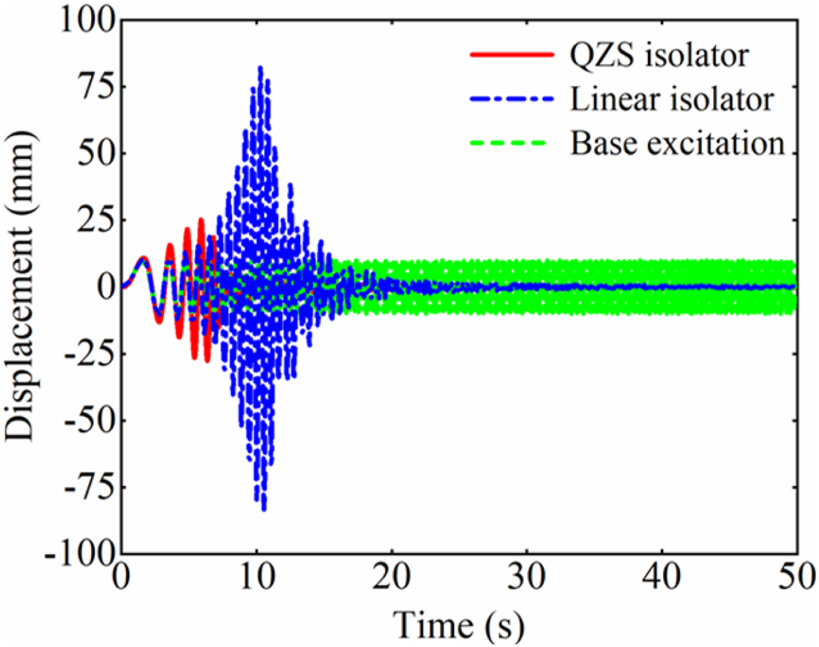
Figure 10 depicts the excitation and displacement response curves for both the BTLS-QZS and the linear system under swept-frequency excitation. Both responses undergo an initial increase followed by a decrease. The BTLS-QZS reaches resonance earlier, exhibiting a significantly lower resonant amplitude and entering the isolation regime ahead of the linear system. Notably, the BTLS-QZS demonstrates a smaller steady-state displacement amplitude than the linear system, confirming its superior vibration isolation performance.
To directly compare the inherent frequency and displacement transmissibility ADAMS simulation results for the displacement transmissibility rate 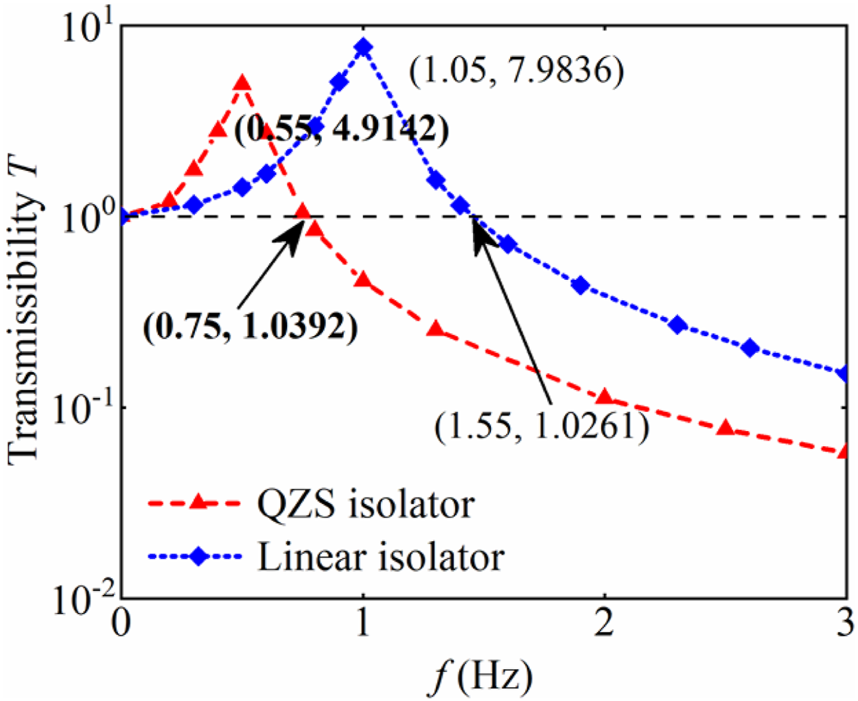
As shown in Figure 11, the BTLS-QZS exhibits an initial isolation frequency of 0.75 Hz and a resonance frequency of 0.55 Hz, with a peak displacement transmissibility of 4.19. In comparison, the linear system has corresponding values of 1.55 Hz, 1.05 Hz, and 7.98, representing reductions of 51.61%, 47.62%, and 47.46%, respectively. These results demonstrate that the designed BTLS-QZS effectively reduces displacement transmissibility and provides superior vibration isolation.
4.2. Low-frequency vibration experiment
In this subsection, static and dynamic low-frequency vibration experiments are conducted to validate the accuracy of the theoretical analysis. To minimize inter-component friction and enhance the precision of the isolator, key components were manufactured using CNC machining.
Experimental parameters of the BTLS-QZS isolator.
As illustrated in Figure 12(a), the base of the BTLS-QZS was mounted securely to the base of an Edelberg HLD spiral tensile testing machine. A static test was performed by gradually actuating the manual loading device. Force and displacement data were acquired and displayed in real-time on a digital stroke indicator and a force gauge, respectively. Figure 12(b) presents the experimental force-displacement curves for three configurations: the linear isolator, the negative stiffness vibration isolator, and the BTLS-QZS. Except for the latter segment of the curve, where the vertical linear spring approached its compression limit, the experimental data show good agreement with the theoretical predictions. (a) Static experimental setup for the BTLS-QZS isolator; (b) experimental results of static verification.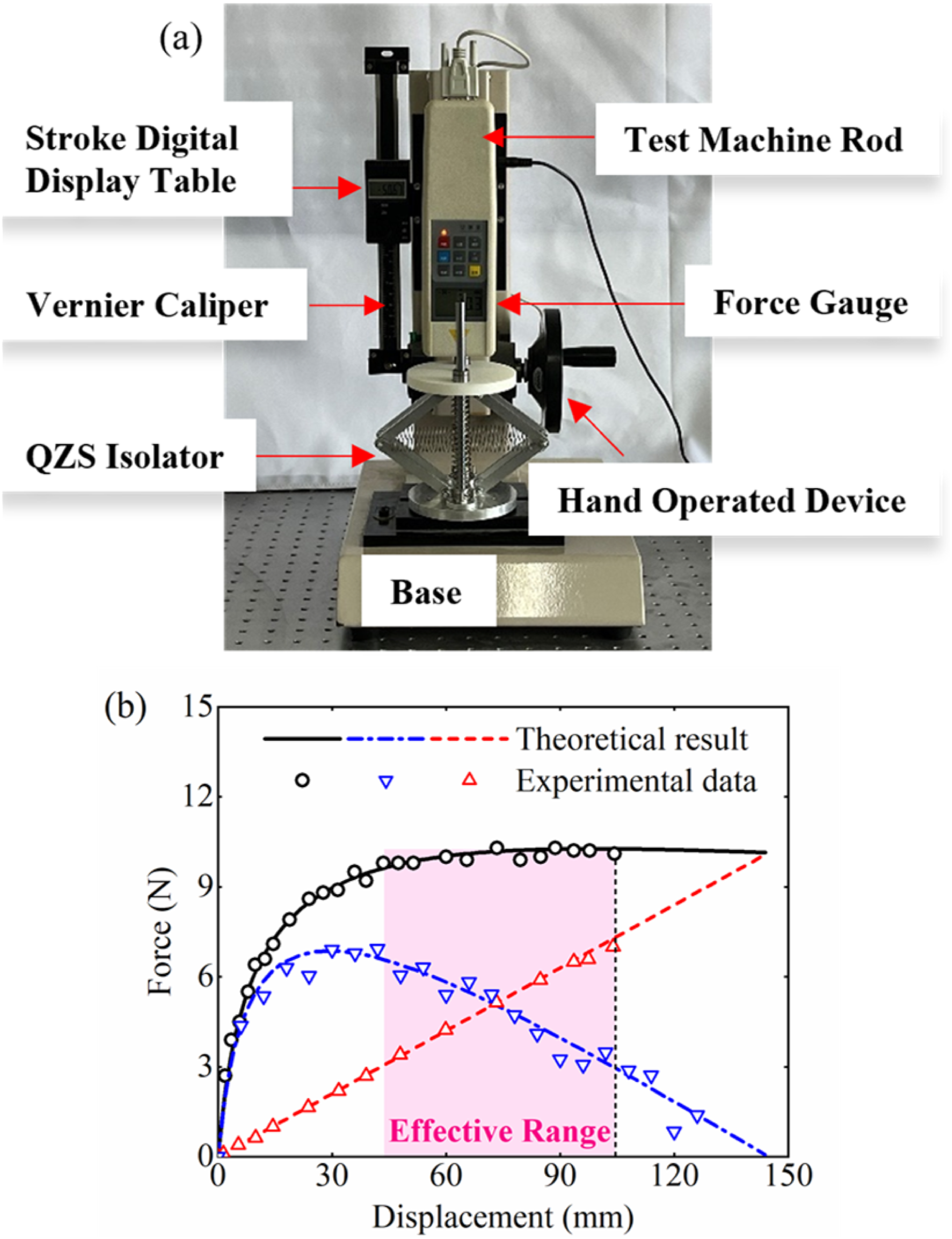
Based on the static test verification, the designed BTLS-QZS vibration isolator was fixed on a low-frequency excitation platform (200N TIRA vib) for the experimental verification of harmonic vibration. As depicted in Figure 13(a), two accelerometers were positioned on the upper platform and the base to acquire the input and response acceleration signals. The signals designed by the Computer are generated by the Controller to ensure the accuracy of the input acceleration signals, and then by the Power Amplifier to drive the Vibration Shaker, and the signals collected by the Accelerometer can be processed by the Computer to the transmission rate of the vibration isolator and the shaker. The experimental transmissibility of the BTLS-QZS within 20 Hz is plotted in Figure 13(b), showing good agreement with theoretical predictions and a monotonic improvement in vibration isolation effect with increasing frequency. (a) Experimental setup for verification of the BTLS-QZS isolator; (b) experimental results of dynamic verification.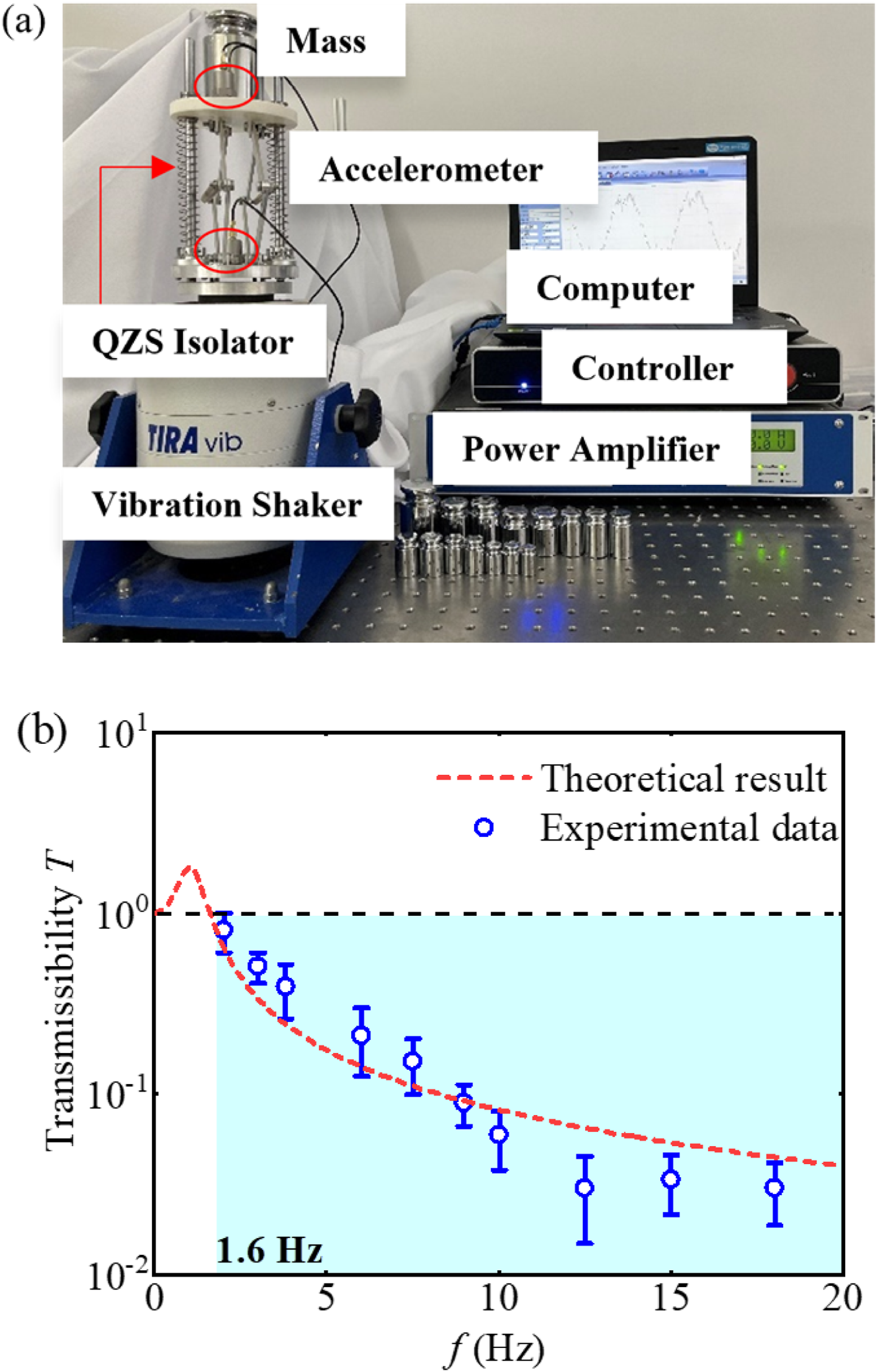
The acceleration time-history data of both the BTLS-QZS and the linear isolator under constant-frequency excitations are presented in Figure 14. The time-domain responses demonstrate that the BTLS-QZS enters the effective isolation regime earlier than its linear counterpart. Furthermore, as illustrated in Figure 14, the BTLS-QZS maintains a more pronounced vibration attenuation advantage over the linear isolator across the increasing excitation frequencies. The response and base excitation in time domain under periodic excitation.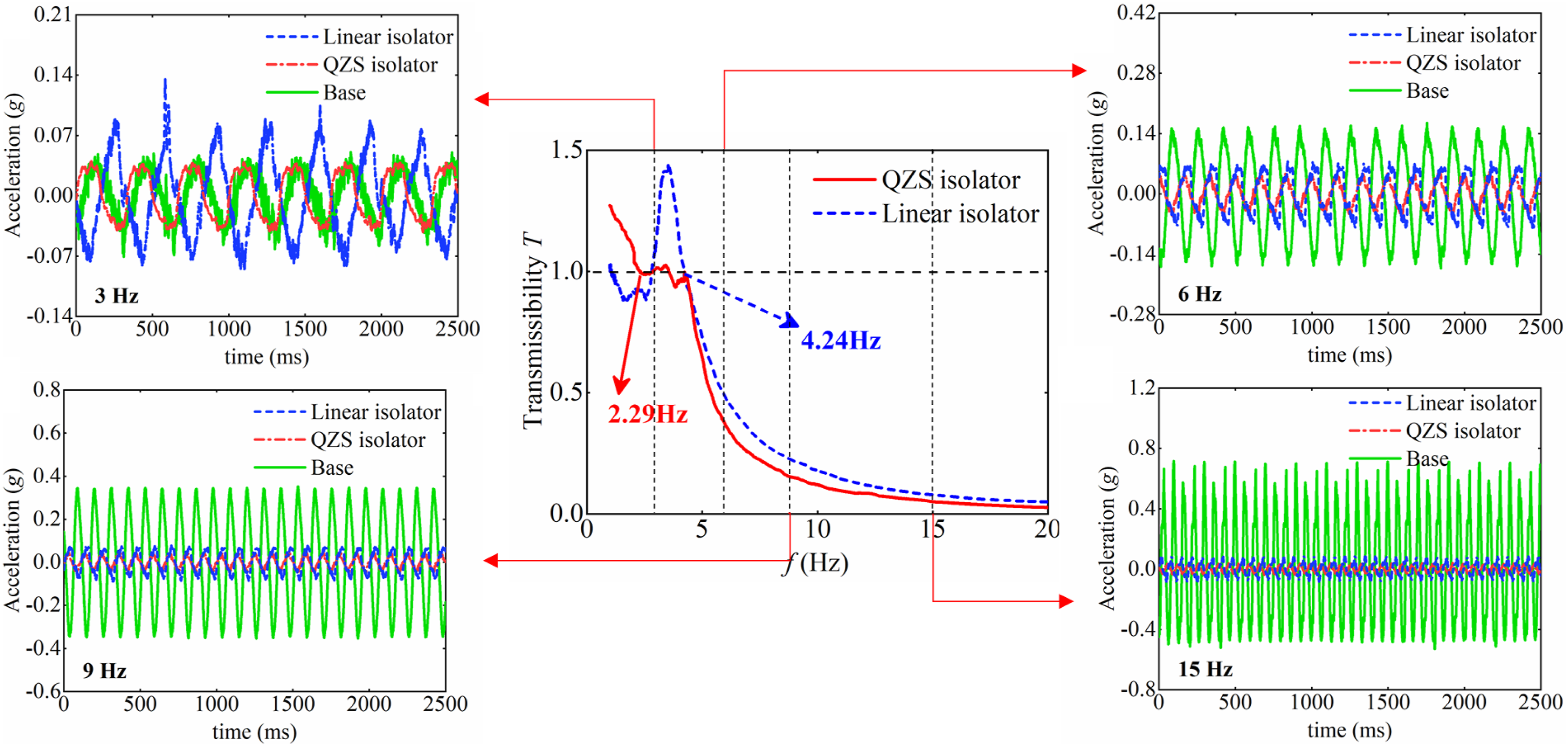
Figure 14 also presents a comparison of the transmissibility for the BTLS-QZS and the linear isolator under different excitation amplitudes. The base was subjected to sweep excitations with varying amplitudes over a frequency range of 1 to 20 Hz. In agreement with the theoretical analysis, increasing the excitation amplitude elevates both the peak transmissibility and its corresponding frequency for both systems. Critically, the experimental data confirm that the BTLS-QZS possesses a lower initial isolation frequency, measured at 2.29 Hz versus 4.23 Hz for the linear isolator, representing a reduction of 45.86%.
Figure 15 shows the displacement transmissibility of the BTLS-QZS and the corresponding linear isolator under different conditions. The first two figures of Figure 15 discuss the influence of different load mass Results of low-frequency vibration tests under different conditions.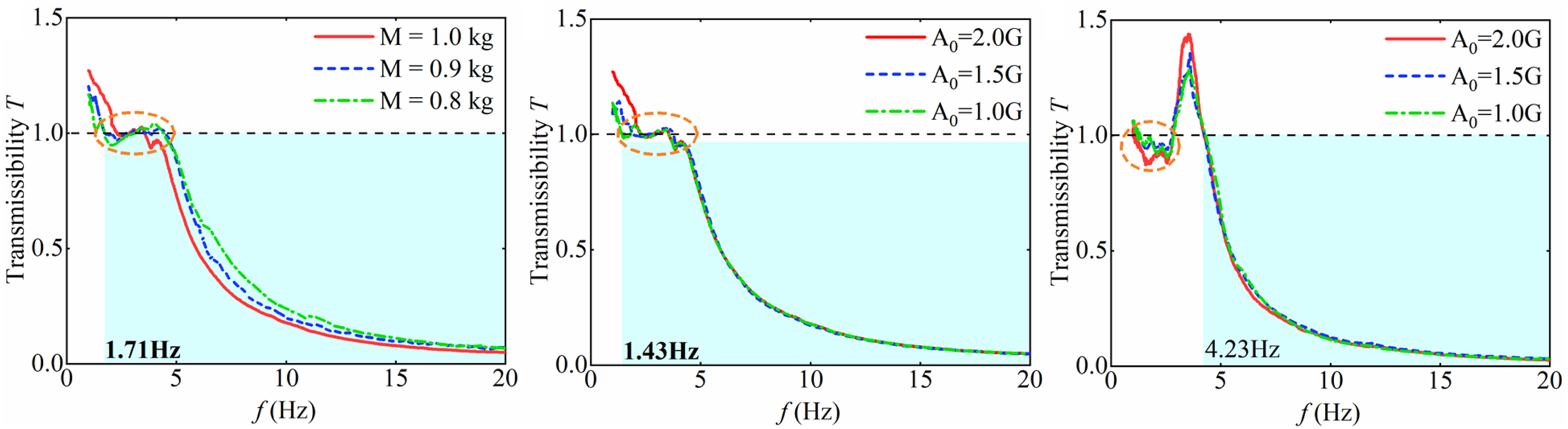
Notably, the transmissibility of the BTLS-QZS in Figure 15 exhibits an interval where the transmissibility remains close to 1 after the resonance peak. This region is highlighted by the orange circle. Observation of the experimental process reveals that frictional self-locking occurs at multiple hinges of the BTLS-QZS vibration isolator and at the guiding rods when passing through the resonance frequency, which affects the further decrease of the transmissibility rate. However, the friction effect decreases relative to the excitation output as the frequency increases further. The self-locking phenomenon disappears and the transmissibility rate decreases as frequency increases. In contrast, the frequency sweep results for the linear isolator reveal that self-locking (indicated by the orange circle) occurs prior to the resonance frequency. This behavior is attributed to the influence of ultra-low-frequency excitation. Its driving force of the vibration shaker is not enough to vibrate the vibration isolator weight and the mass, resulting in the value of the longitudinal coordinates of the transmissibility rate curve fluctuating around the 1 neighborhood.
Figure 15 illustrates that a higher load mass reduces the initial isolation frequency but elevates the resonance peak, while simultaneously enhancing mid to high frequency isolation more significantly. Figure 15 also concludes that increasing the excitation amplitude raises both the resonance peak and the initial isolation frequency, with a comparatively minor effect on mid to high frequency performance. Consequently, to optimize the low-frequency advantages of the BTLS-QZS, its design must carefully balance the expected load conditions and the actual excitation environment.
5. Conclusion
This paper presents a novel BTLS-QZS isolator inspired by the skeletal structure of turtle limbs. The design employs a combined positive-negative stiffness compensation mechanism, and its dynamic behavior is theoretically analyzed using the harmonic balance method. Comparisons with conventional three-spring and linear isolators verify its superior low-frequency vibration isolation performance. The principal findings and contributions of this work are summarized below. (1) Innovative bionic structure design: A bio-inspired QZS structure is conceived by emulating the geometric configuration of turtle limbs through rigid links and linear springs. This design allows the positive stiffness compensation and load-bearing capacity to be tuned via parameter adjustment, enabling effective low-frequency vibration isolation across a range of loads. (2) High load-bearing characteristics: The BTLS-QZS demonstrates superior performance relative to the traditional three-spring QZS isolator, achieving a 46.02% higher load capacity and a 30% wider quasi-zero-stiffness band. Furthermore, unfavorable nonlinear stiffness hardening phenomenon occurs only when the load at the time of vibration is greater than 3.2 times of the rated load. (3) Superior low-frequency effective isolation: The low-frequency vibration isolation performance is characterized through dynamic modeling and harmonic balance analysis. Results demonstrate that the designed BTLS-QZS possesses HSLDS characteristics, effectively reducing both the initial isolation frequency and the resonance peak. Parametric analysis further reveals that increasing the load mass, decreasing the damping coefficient, raising the excitation amplitude, or increasing the third-order nonlinear coefficient are identified as factors that can induce nonlinear jumping phenomena, thereby compromising system stability. (4) Dual validation through ADAMS and experimentation: The dynamic performance and transmissibility of the BTLS-QZS were verified through a combination of ADAMS and low-frequency vibration experiments, conducted under both swept-frequency and fixed-frequency excitations. The results confirm its effective isolation capability.
Footnotes
Funding
The authors disclosed receipt of the following financial support for the research, authorship, and/or publication of this article: This research was supported by National Natural Science Foundation of China (Grant No. 52422504, No. 52175084).
Declaration of conflicting interests
The authors declared no potential conflicts of interest with respect to the research, authorship, and/or publication of this article.