
Abstract
The Switched Reluctance Motor (SRM)-planetary gear electric drive system shows significant application potential, but its dynamic characteristics are severely impacted by strong nonlinear factors and electromechanical coupling effects. This study established an electromechanical coupling dynamic model of the SRM electric drive system, using translational and angular displacements as generalized coordinates, to investigate the system’s internal/external excitations and nonlinear factors. The model comprehensively considers factors such as core magnetic saturation, the spatio-temporal distribution of electromagnetic forces, component flexibility, and installation errors. To verify the model’s accuracy, an experimental test rig was constructed. A comparison of phase currents and vibration accelerations under steady-state conditions confirmed that the simulation and experimental results exhibit good consistency. Through simulation, key internal factors that are difficult to isolate experimentally, such as motor torque ripple, rotor eccentricity, gear errors, and housing flexibility were analyzed, revealing their influence mechanisms. To further ascertain the system’s response characteristics under real-world dynamic operating conditions, the vibration response laws under different external operating conditions of input speed and load torque were explored through experiments. This research, integrating simulation and experimentation, clarifies the influence mechanisms of internal factors and external conditions on the system’s dynamic characteristics, providing a basis for resonance avoidance and optimal design.
Keywords
1. Introduction
The electrification of power transmission systems in engineering machinery and special vehicles is accelerating, driven by carbon neutrality goals. The Switched Reluctance Motor (SRM), owing to its advantages of being rare-earth-free, low-cost, and having high starting torque, shows great potential as an electric drive system when combined with the compact structure and high load-carrying capacity of planetary gear transmissions. However, this system is a complex electromechanical coupled system, characterized by numerous nonlinear factors, such as SRM core magnetic saturation, time-varying mesh stiffness of gears, and manufacturing and installation errors. The large torque ripple and radial force fluctuations of the SRM are transmitted as excitation to the gear system, worsening its meshing performance. Concurrently, the trend towards system integration and lightweight design increases component flexibility, which can easily lead to rotor eccentricity and deterioration of the gear meshing performance, resulting in highly complex coupling mechanisms.
Regarding SRM dynamics research, Srinivas and Arumugam (2004) employed the finite element method (FEM) to investigate the 3D modal analysis of all SRM components, rotor unbalance dynamics, and stress analysis under different loads. Safdarzadeh et al. (2019) proposed building an SRM model based on a position function and used FEM to improve the analytical method. Hu et al. (2022) established a multi-physics model of an SRM, considering structural orthotropy and non-uniformly distributed electromagnetic forces. Wang et al. (2020) established a transverse analytical vibration model based on the interaction between radial magnetic pull and vibration displacement to study the transverse vibration of an eccentric SRM rotor. However, the aforementioned SRM dynamic models do not comprehensively consider factors such as core magnetic saturation, motor torque ripple, and component flexibility. Similarly, studies on planetary gear systems have employed TCA for flexible deformation (Tsai and Ye, 2018), FEM for modal analysis (Ericson and Parker, 2013), and rigid-flexible coupling models to study component flexibility and load-sharing (Fan et al., 2020; Liu et al., 2023).
Currently, electromechanical coupling dynamics research related to SRMs mainly focuses on the coupling dynamics between radial electromagnetic force and the stator housing, with significant research gaps in the electromechanical coupling dynamics of SRM and gear transmission systems. Callegaro et al. (2019) analyzed the harmonic components of radial force density, explaining the mechanism by which harmonic components cause stator resonance. Kimpara et al. (2019) used FEM for vibration analysis of an SRM assembly, studying the influence of radial electromagnetic force and mechanical coupling structure on stator and rotor vibration. Wang et al. (2021) established an analytical model for the radial electromagnetic force of an SRM, studying the coupling effect between radial electromagnetic force and stator-rotor vibration, and on this basis, analyzed the nonlinear coupled vibration of an eccentric rotor (Wang et al., 2020). Chen et al. (2022) established an electromechanical coupling dynamic model of an SRM electric drive system considering component flexibility, studying the influence of the universal joint on the system’s dynamic characteristics under different operating conditions. However, most coupling studies lack detailed consideration of component flexibility such as motor housing, shaft, and gearbox housing. Liu et al. (2017) established an electromechanical coupling dynamic model for the induction motor-gear transmission system of a shearer’s cutting unit, analyzing the electromechanical coupling dynamic characteristics during variable-speed processes. Bai et al. (2018) coupled an induction motor model with a planetary gear system model to study the coupling interaction between the motor and the gear system. Chen et al. (2021) established an electromechanical coupling dynamic model for a wind turbine generator set, considering nonlinear factors such as time-varying gear mesh stiffness and generator electromagnetic characteristics, and analyzed the system’s dynamic characteristics under different external excitations. Yi et al. (2018) established an electromechanical coupling dynamic model for a multi-stage gear transmission electric drive system, studying the influence of electromagnetic effects on the system’s natural characteristics.
In summary, existing dynamic models for SRM electric drive systems lack comprehensive consideration of iron core magnetic saturation, spatial-temporal distribution of electromagnetic forces, component flexibility, and diverse manufacturing and installation errors. Besides, insufficient research has been conducted on system dynamic characteristics under variable-speed and variable-load conditions. The contributions of this paper are as follows: (1) An electromechanical coupling dynamic model of the SRM electric drive system is established, taking core magnetic saturation, torque ripple and component flexibility into full account. (2) Combined simulation and experimental methods are adopted to verify model accuracy, and the influences of key internal factors such as motor torque ripple, manufacturing and installation errors, and component flexibility on system dynamic performance are analyzed. (3) The dynamic characteristics and operating laws of the system under variable-speed and variable-load conditions are revealed, which provides a theoretical basis for system resonance suppression and optimal structural design.
2. System dynamics modeling
As shown in Figure 1, the SRM is connected to the sun gear via a rigid coupling. Torque is transmitted through the planet gears to the planet carrier, while the ring gear is fixed to the housing. The sun and planet gears, which have greater rigidity, are treated as rigid bodies, and their lumped-parameter dynamic models are established. Simultaneously, to better reflect the impact of component flexible deformation on system performance, finite element (FE) condensation models are established for the motor housing, stator-rotor, planet carrier, internal ring gear, and gearbox housing. By coupling the lumped-parameter models with the FE condensation models, an electromechanical coupling dynamic model of the SRM electric drive system considering component flexibility is obtained. Switched reluctance motor—planetary gear electric drive system schematic.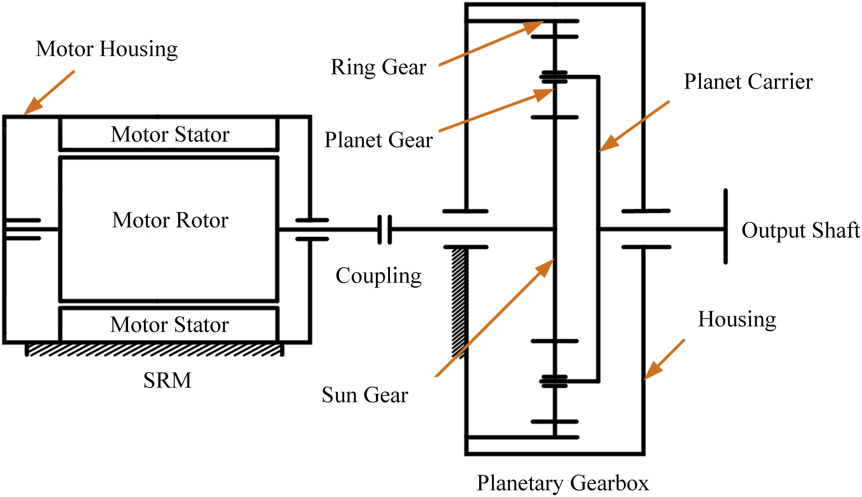
2.1. Switched reluctance motor (SRM) dynamics model
A three-phase 12/8-pole SRM is used. A dynamic model of the SRM is established by combining analytical methods with the finite element method.
2.1.1. Torque model
The mathematical model for SRM operation is shown in equation (1), which includes the circuit equation, the electromechanical relationship equation, and the mechanical motion equation, from top to bottom
However, during SRM operation, the iron core is highly magnetically saturated, making it difficult to analytically calculate the phase flux linkage
SRM operation is cyclical with the rotor pole pitch. An FE analysis is performed within one rotor pole pitch (45°). FE calculations are carried out at various discrete values of rotor angle and current to export the phase flux linkage corresponding to different angles and currents. These are then interpolated to obtain a fine-grained numerical matrix of phase flux linkage. According to equation (2) and the phase flux linkage interpolation matrix, the phase inductance-angle curves for different phase currents can be obtained

Based on the phase inductance-angle curves, the differential of phase inductance with respect to angle at a constant phase current can be calculated. Substituting this into Equation (1), a numerical matrix of phase electromagnetic torque can be computed. Using this matrix, the phase electromagnetic torque at any angle and current can be obtained through 2D interpolation. The total electromagnetic torque is found by superposition, which then yields the tangential electromagnetic force
2.1.2. Motor radial force model
Based on the Maxwell stress tensor theory, the radial electromagnetic force produced by a single stator pole on the rotor can be expressed as
According to the equivalent magnetic circuit method, the magnetic circuit equation for the overlapping region of the stator and rotor poles is
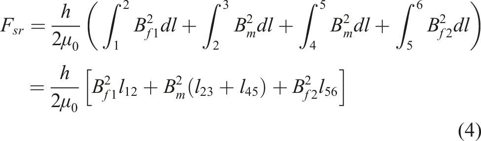
Taking Bf1 as an example, the magnetic circuit equation for the non-overlapping region of the stator and rotor poles is
2.2. Planetary gear system dynamics model
2.2.1. Lumped-parameter model
The dynamic model of the planetary gear system is shown in Figure 2. This model has two main features: (1) It uses translational and angular displacements as generalized coordinates; (2) It considers the influence of the non-inertial reference frame. Dynamic model of the planetary gear system.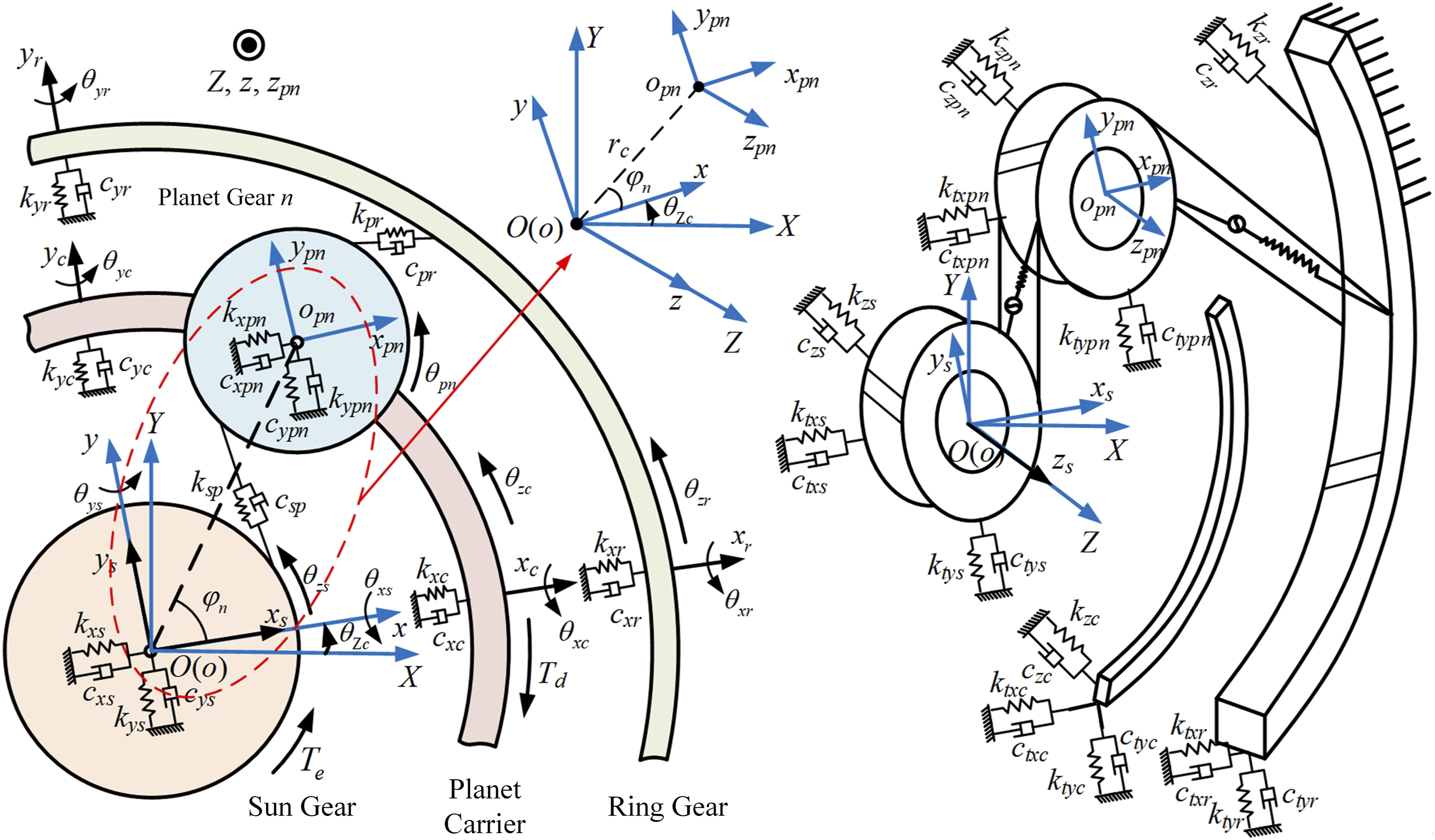
There are three types of coordinate systems in the figure: (1) The stationary coordinate system OXYZ; (2) The planet carrier moving coordinate system oxyz, which rotates at a constant speed with the planet carrier and shares the same origin as the stationary coordinate system OXYZ; (3) The n-th planet gear moving coordinate system o pn x pn y pn z pn (n = 1, 2, …, N, where N is the number of planet gears), whose origin is at the theoretical center o pn of the n-th planet gear, with its axes parallel to the axes of the planet carrier moving coordinate system oxyz.
The subscripts s, c, r, and p n denote the sun gear, planet carrier, ring gear, and n-th planet gear, respectively. x i , y i , z i (i = s, c, r, p n ) are the translational displacements of each component in the x, y, and z directions within the moving coordinate system oxyz. θ mi (m = x, y, z; i = s, c, r) are the angular displacements of the sun gear, planet carrier, and ring gear in the x, y, and z directions within the moving coordinate system oxyz. θ Zc is the angular displacement of the planet carrier in the Z direction of the stationary coordinate system OXYZ. θ pn is the angular displacement of the planet gear in the z pn direction of its own moving coordinate system. k mi and c mi (m = x, y; i = s, c, r, p n ) are the support stiffness and support damping of each component in the x, y, and z directions. k tmi and c tmi (m = x, y; i = s, c, r, p n ) are the torsional support stiffness and damping of each component in the x and y directions. k sp and c sp are the meshing stiffness and damping of the external (sun-planet) mesh. k pr and c pr are the meshing stiffness and damping of the internal (planet-ring) mesh. φ n is the angle of the n-th planet gear relative to the x-axis. r c is the radius of the planet carrier. T e is the torque output from the SRM to the planetary gear system. T d is the load torque acting on the planet carrier.
Using the slicing method to solve for the gear pair meshing forces and torques, and considering the influence of the non-inertial frame, the dynamic equations for the sun gear are
Where m s is the mass of the sun gear; J xs , J ys , J zs are the moments of inertia of the sun gear about its own x, y, and z axes; M dEsn is the meshing damping torque of the n-th external mesh pair; the meanings of the other parameters are the same as shown in Figure 2.
The dynamic equations for the n-th planet gear are
Where m pn , J xpn , J ypn , J zpn are the mass and moments of inertia about its own x, y, and z axes for the n-th planet gear; δ xpnc , δ ypnc , δ zpnc , δ θxpnc , δ θypnc are the relative translational and angular displacements between the n-th planet gear and the planet carrier pin in each direction; i spn is the transmission ratio of the n-th external mesh pair; M dIpn is the meshing damping torque of the n-th internal mesh pair.
2.2.2. Flexible component condensation model
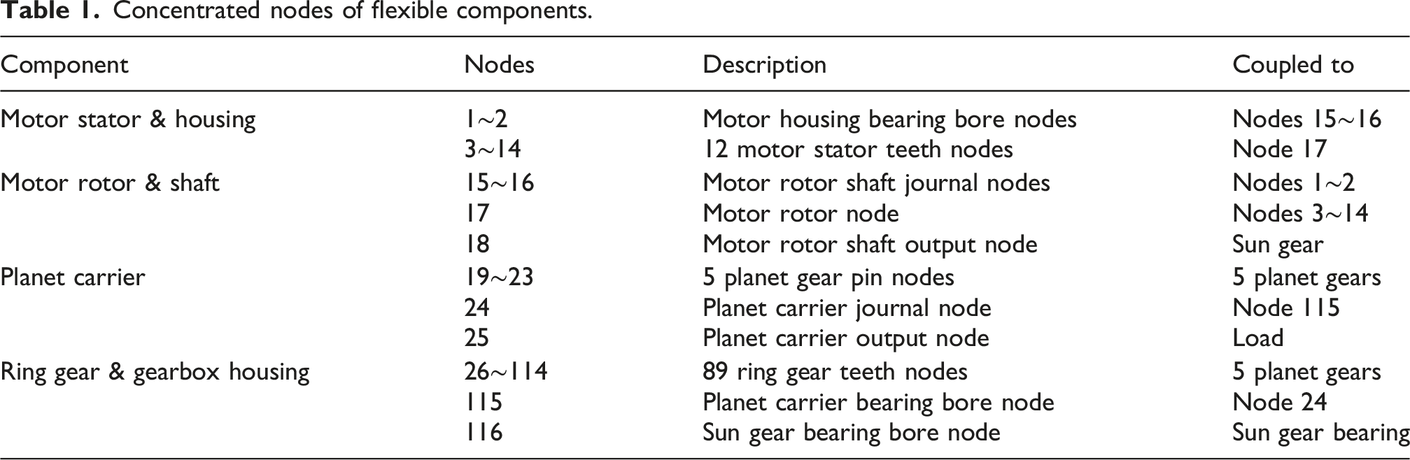
Based on modal condensation theory, FE condensation models are established for the planet carrier, internal ring gear, and gearbox housing. To couple the forces and displacements between different components, concentrated nodes are established on the FE condensation models, as shown in Figure 3. A total of 116 concentrated nodes are established on the flexible component FE condensation models. The specific meanings and coupling nodes for each concentrated node are shown in Table 1. Flexible components of the electric drive system and their concentrated node distribution. Concentrated nodes of flexible components.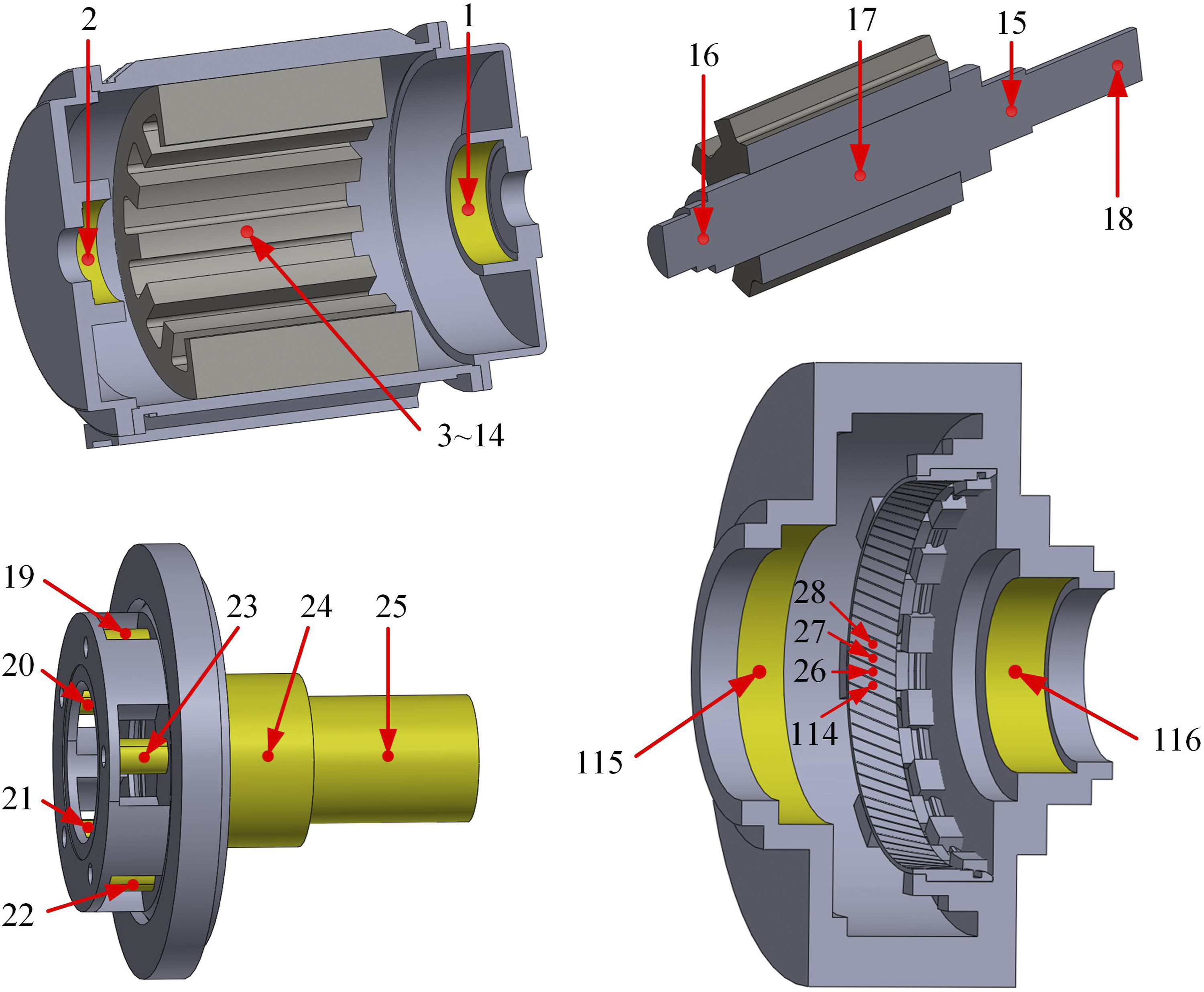
2.2.3. Electromechanical coupling dynamics model
As shown in Figure 4, the electromechanical coupling dynamic model of the switched reluctance motor-planetary gear electric drive system is established by coupling the SRM dynamic model with the rigid-flexible coupling dynamic model of the planetary gear system. Electromechanical coupling dynamic modeling of the electric drive system.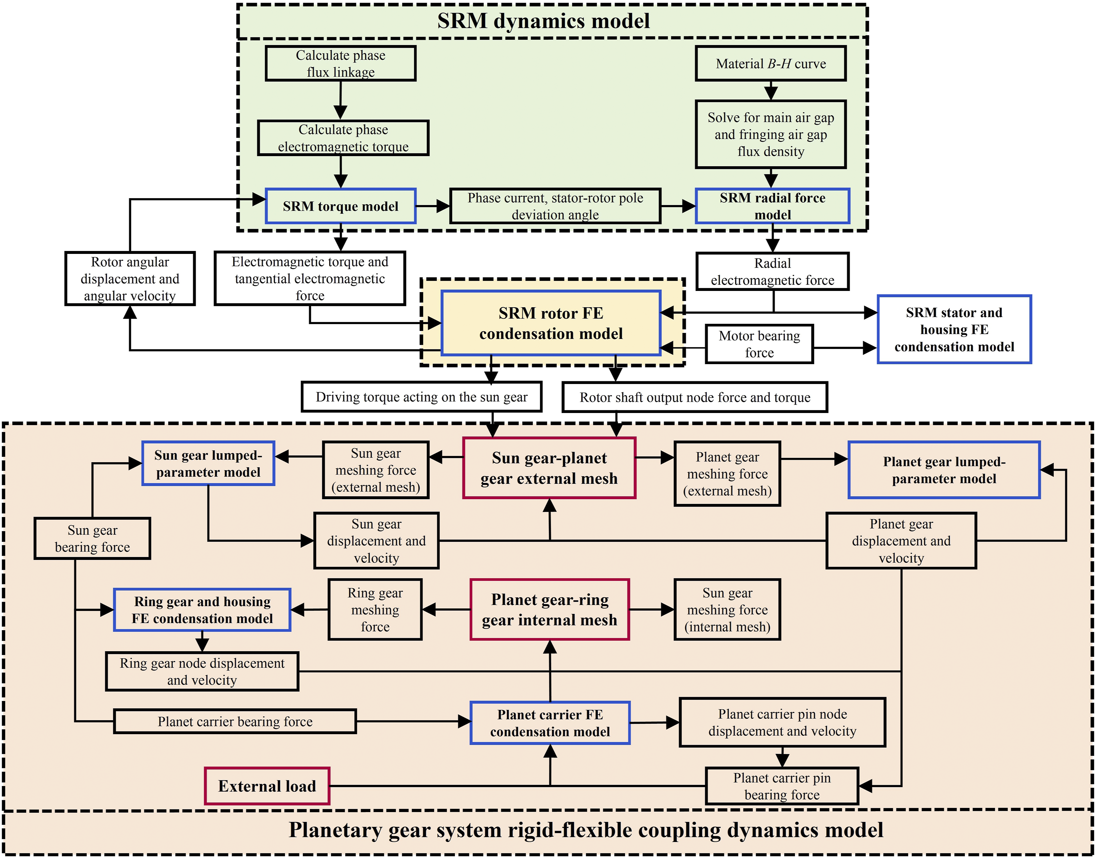
The SRM torque model outputs electromagnetic torque and tangential electromagnetic forces to the condensed finite element model of the rotor. According to phase current and stator-rotor pole deviation angle, the SRM radial force model calculates radial forces between the stator and rotor, and applies them to the condensed finite element models of the rotor, stator and housing.
Under the combined effect of electromagnetic torque, electromagnetic force, bearing force, as well as load force and torque from the sun gear, the rotor condensed finite element model outputs driving torque to the sun gear, and feeds back rotor angular displacement and angular velocity to the SRM torque model.
With the driving torque of the sun gear and external load on the planet carrier, meshing forces of the sun gear, planet gears, and inner gear ring are calculated via the internal and external meshing pair model. By exerting meshing forces on the lumped parameter models of sun & planet gears and the condensed finite element model of inner gear ring, the displacement and velocity responses of each gear node are derived.
Furthermore, bearing forces between adjacent components can be calculated based on the displacement and velocity of coupling nodes. The integrated electromechanical coupling dynamic model of the electric drive system is constructed according to the coupling transmission relationships of force, displacement and velocity between each sub-model.
3. Model validation
3.1. Experimental test rig setup
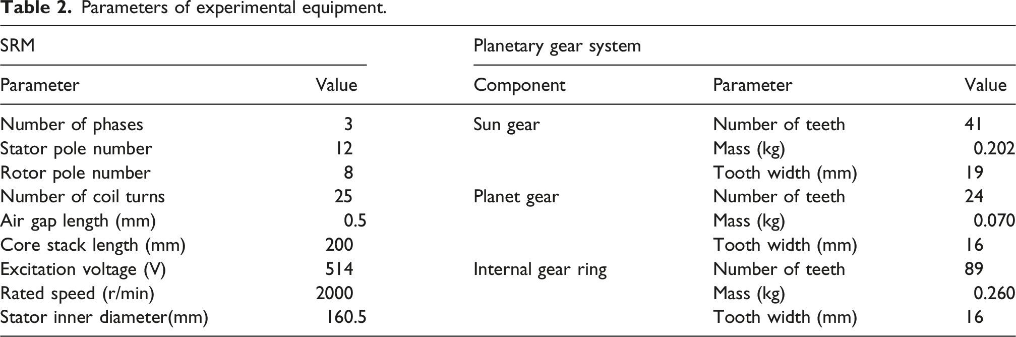
As shown in Figure 5 and Table 2, an SRM-planetary gear electric drive system experimental test rig was constructed. The system consists of a power converter, SRM, planetary gearbox, magnetic powder brake (load), T40 B speed and torque sensor, current sensors, and four IEPE piezoelectric vibration acceleration sensors. The four measurement points are located at the motor bearing (1), sun gear bearing (2), outer surface of the ring gear (3), and planet carrier bearing (4). Rotational speed, torque, vibration acceleration and SRM phase current were measured by corresponding sensors. The measured signals were conditioned by HBM acquisition equipment and saved in the computer. Experimental test rig of the SRM-planetary gear electric drive system. Parameters of experimental equipment.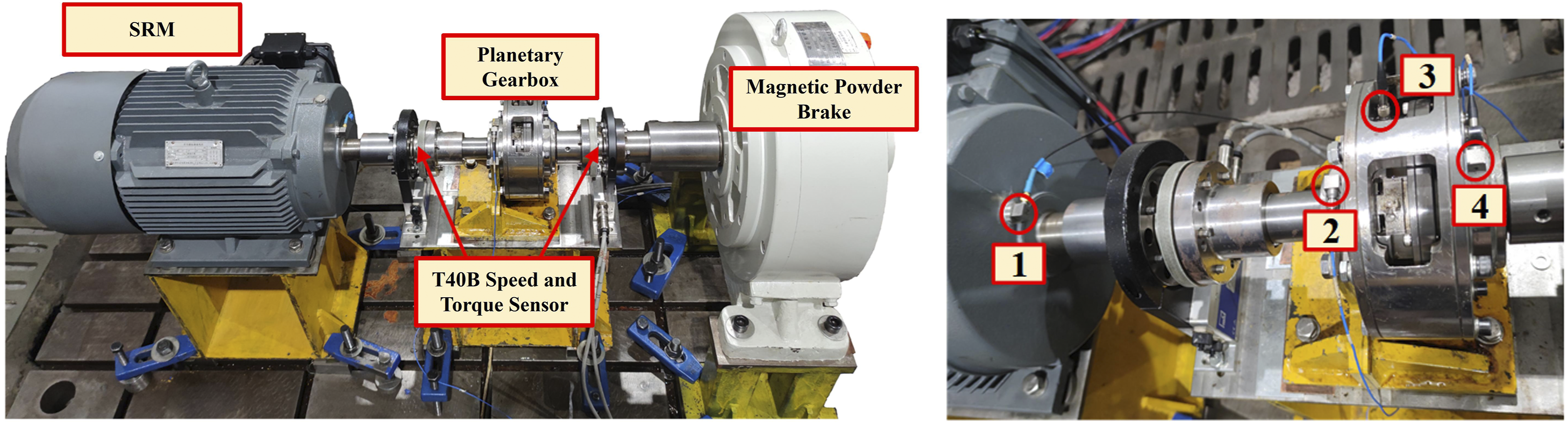
3.2. Model validation
The experimental and simulation results are compared under the operating condition of 2000 r/min input speed and 50 Nm load torque.
From the phase current comparison in Figure 6, it is evident that: the simulation and experimental phase current trends are consistent, with the chopping value being 36A in both. The relative error of the phase current RMS value is 6.32%, showing good agreement. Comparison of experimental and simulation phase currents.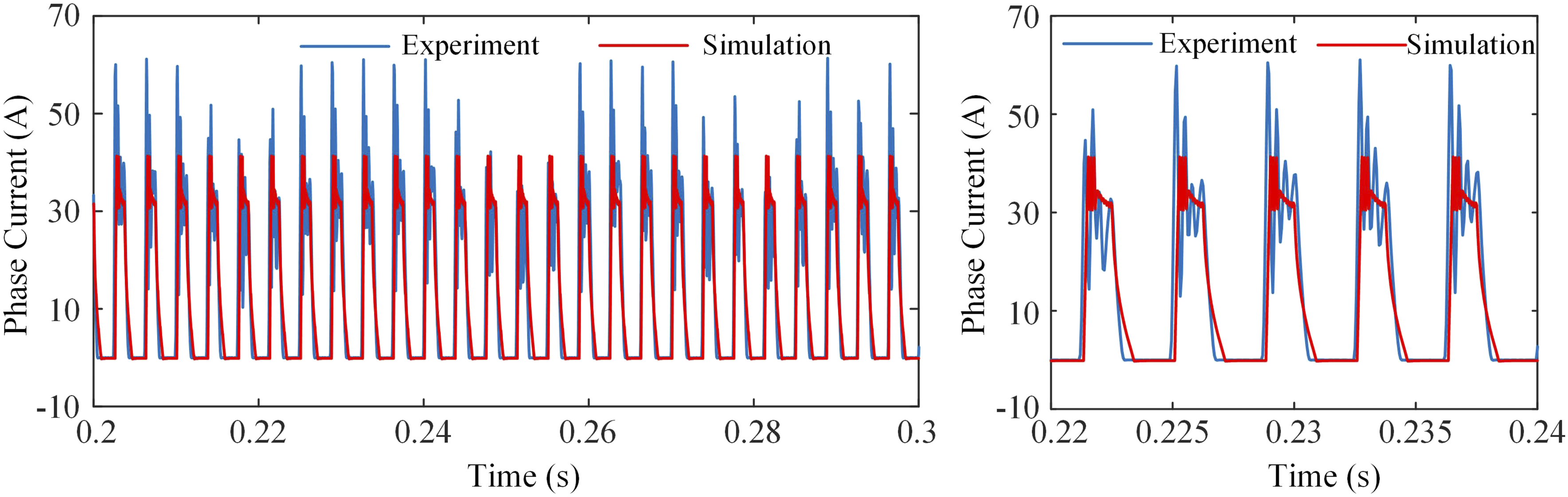
Comparison of experimental and simulation vibration acceleration.
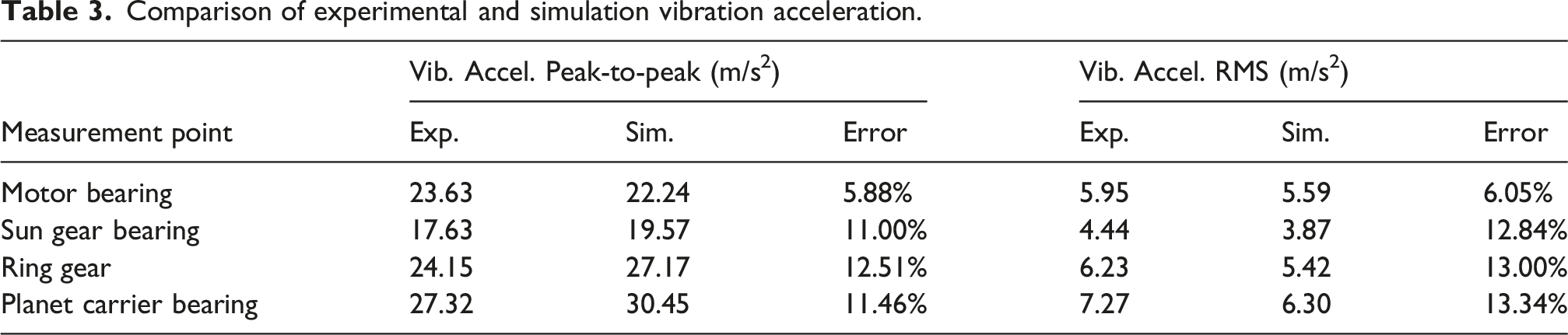
Nevertheless, the dominant frequency components of vibration acceleration at each measuring point are highly consistent, and the amplitude values are close between simulation and experimental results. Therefore, such errors are acceptable. The simulation and experimental results are well matched, which verifies the validity of the established electromechanical coupling dynamic model.
4. System dynamic characteristic analysis
4.1. Simulation analysis: Effect of key parameters on dynamic characteristics
This section utilizes the validated model to analyze key internal factors that are difficult to isolate experimentally.
4.1.1. Effect of motor torque ripple
The SRM speed is set to 2000 r/min, with turn-on and turn-off angles of 1° and 15°, respectively. The mean value of the motor output torque is 150 N·m. All system dynamic characteristics are acquired in the stationary coordinate system OXYZ.
Figure 7 shows the time-domain and frequency-domain plots of the effect of SRM torque ripple on the dynamic meshing torque of the first external mesh pair. It can be seen that SRM torque ripple leads to a deterioration in the gear meshing state, causing an increase in meshing torque fluctuation. The frequency-domain plot shows the appearance of the power supply switching frequency f
D
, with an amplitude approximately 3 times that of the gear meshing frequency f
m
, indicating that the vibration caused by SRM torque ripple is the main factor for the increased amplitude of gear meshing torque vibration. Dynamic meshing torque of the first external mesh pair.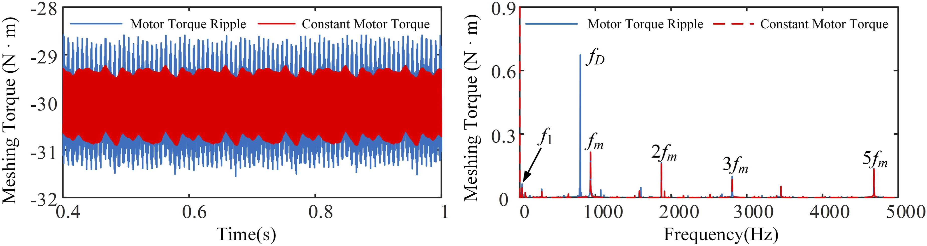
4.1.2. Effect of motor rotor eccentricity
In static eccentricity, the rotor geometric center is offset from the stator geometric center, but the rotor geometric center and the axis of rotation coincide. In dynamic eccentricity, the rotor geometric center and the stator geometric center coincide, but they are offset from the axis of rotation.
Setting the SRM speed to 2000 r/min, static eccentricity e
s
= 0.1 mm, and deflection angle θ
es
= 0 rad, it is observed that after static eccentricity is introduced, the mean value of the X-direction dynamic bearing force at the motor output end changes more significantly than that of the Y-direction, due to the static eccentricity being applied in the X-direction. The dominant frequency components of both X and Y-direction bearing forces are the power supply switching frequency f
D
, phase current frequency f
ph
, its harmonic 2f
ph
, and gear meshing frequency f
m
, with larger amplitudes of f
D
and f
ph
in the X-direction than in the Y-direction. Additionally, the amplitudes of electromagnetic frequencies and gear meshing frequency increase significantly, indicating that static rotor eccentricity has a considerable effect on the motor bearing force, as shown in Figure 8. Dynamic bearing force at the motor output end (static eccentricity).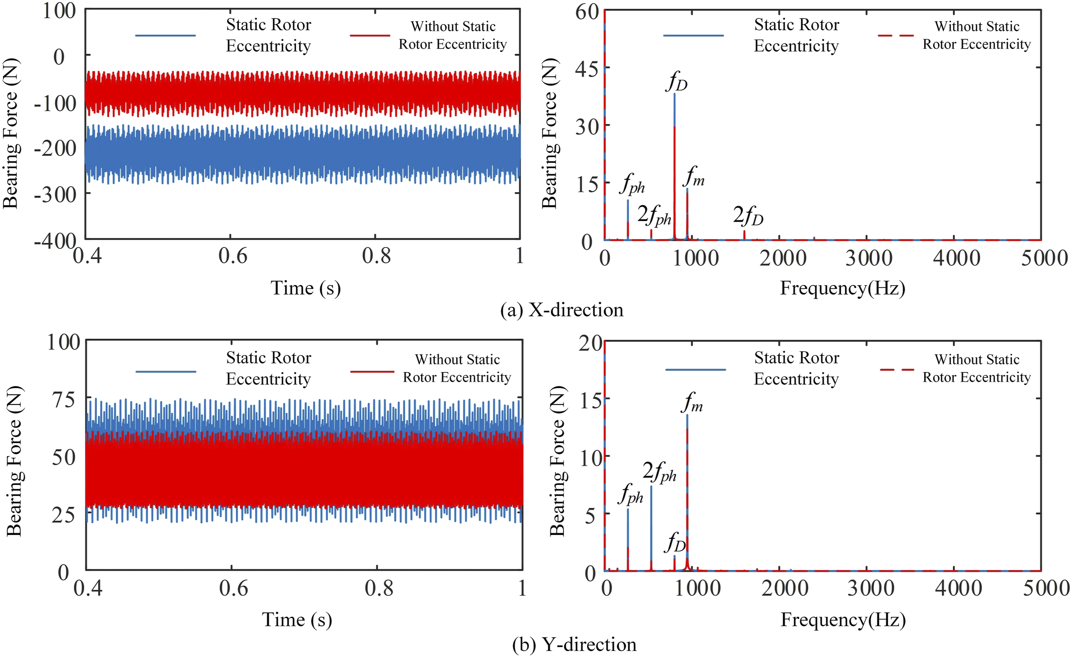
At an SRM speed of 2000 r/min and a dynamic eccentricity rate of 20%, the time-domain plot in Figure 9 shows that the mean values of X- and Y-direction dynamic bearing forces remain unchanged after dynamic rotor eccentricity, while their vibration amplitudes increase distinctly and the bearing forces present obvious low-frequency periodicity. According to frequency spectra, amplitudes of electromagnetic frequencies f
D
and f
ph
rise, and large-amplitude input shaft rotational frequency f1 appears. As f1 equals the motor rotational frequency, it indicates that periodically varying electromagnetic forces are transmitted to the motor output bearing. In conclusion, dynamic rotor eccentricity intensifies motor bearing vibration more significantly than static eccentricity. Dynamic bearing force at the motor output end (dynamic eccentricity).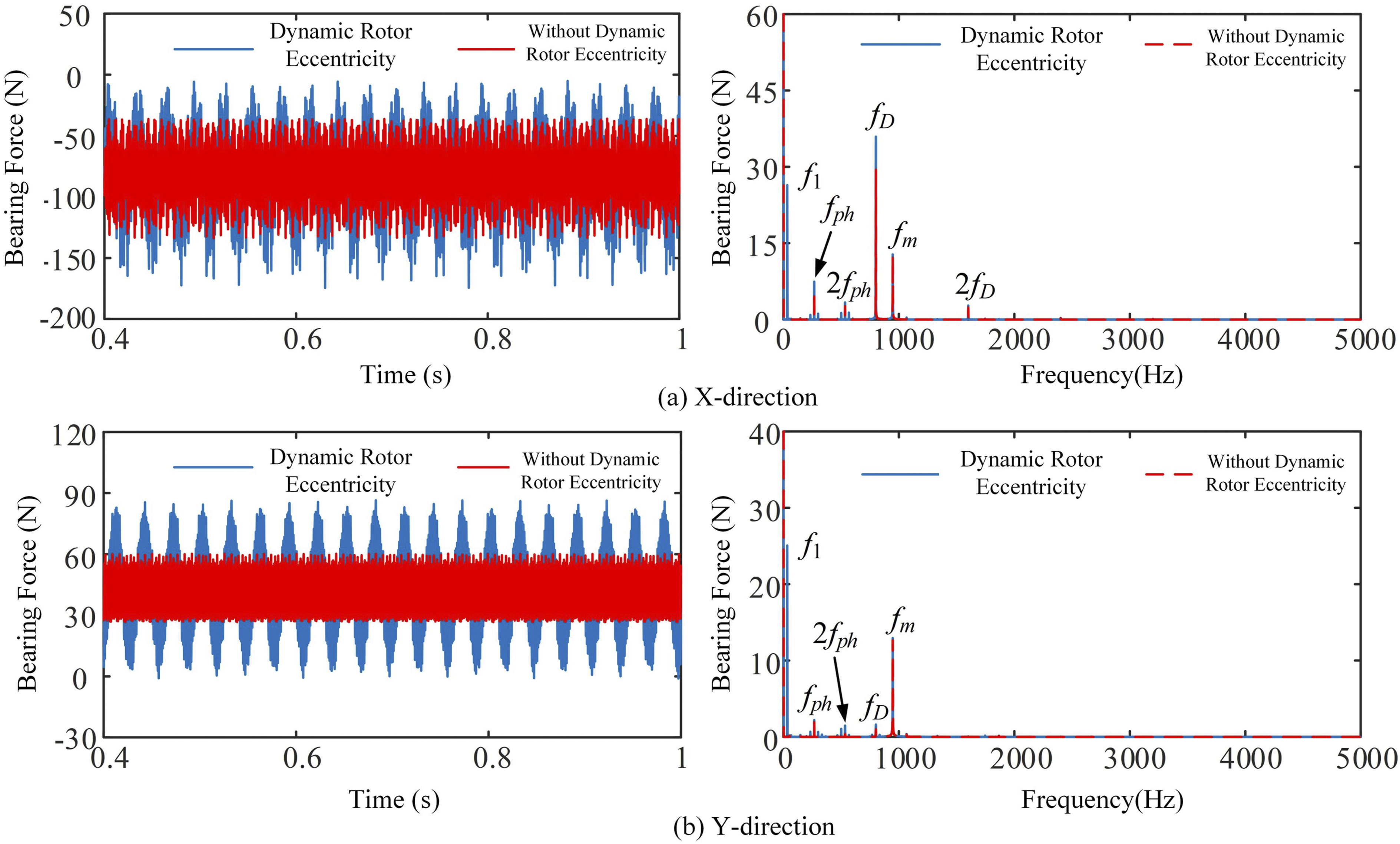
4.1.3. Effect of gear error
The effect of tooth profile error on the dynamic meshing torque of the first external mesh pair at SRM speeds of 2000 r/min, 6000 r/min, and 10,000 r/min was studied, and the results show that as the speed increases, the influence of tooth profile error on the meshing torque becomes more significant. After introducing a 5 μm tooth profile error, the mean value of the meshing torque remains unchanged at all three speeds, but the amplitudes all increase to varying degrees, indicating that tooth profile error causes an increase in the fluctuation of the external mesh dynamic torque. As shown in Figure 10, taking the 10,000 r/min results as an example, after introducing tooth profile error, the amplitudes of the gear meshing frequency f
m
and its harmonics nf
m
increase. In particular, the amplitudes of high-order meshing frequencies (2f
m
, 4f
m
, 5f
m
, etc.) show a more pronounced increase, while the amplitude of the power supply switching frequency f
D
only increases slightly. This is because tooth profile error is a high-frequency error distributed across all points on the tooth flank. Accounting for tooth profile error is equivalent to introducing a high-frequency displacement excitation during gear meshing, thus increasing the meshing torque fluctuation and significantly increasing the amplitudes of high-order meshing frequencies. Dynamic meshing torque of the first external mesh pair (10,000 r/min).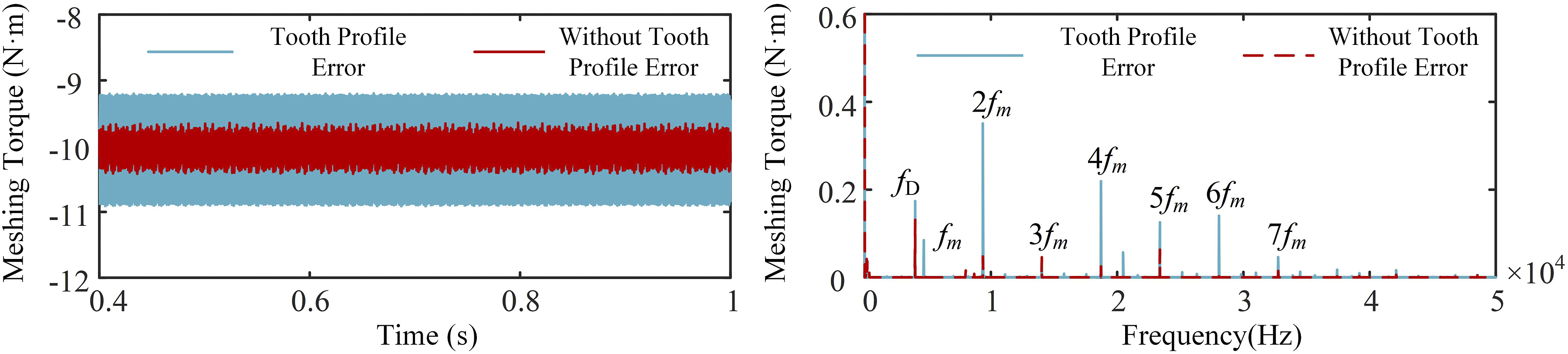
4.1.4. Effect of housing flexibility
As shown in Figure 11, coupling the flexible gearbox housing significantly reduces the meshing torque amplitude. This is because the flexible housing absorbs vibration energy, which reduces the amplitudes of the gear meshing frequency fm and its harmonics nfm (2f
m
, 3f
m
, 5f
m
). Furthermore, the flexible housing suppresses high-order rotational frequency harmonics including 5f1 and 10f1, and reduces complicated irrelevant frequency components. Without the flexible housing, this energy is not absorbed, leading to more complex frequency components. Dynamic meshing torque of the first external mesh pair.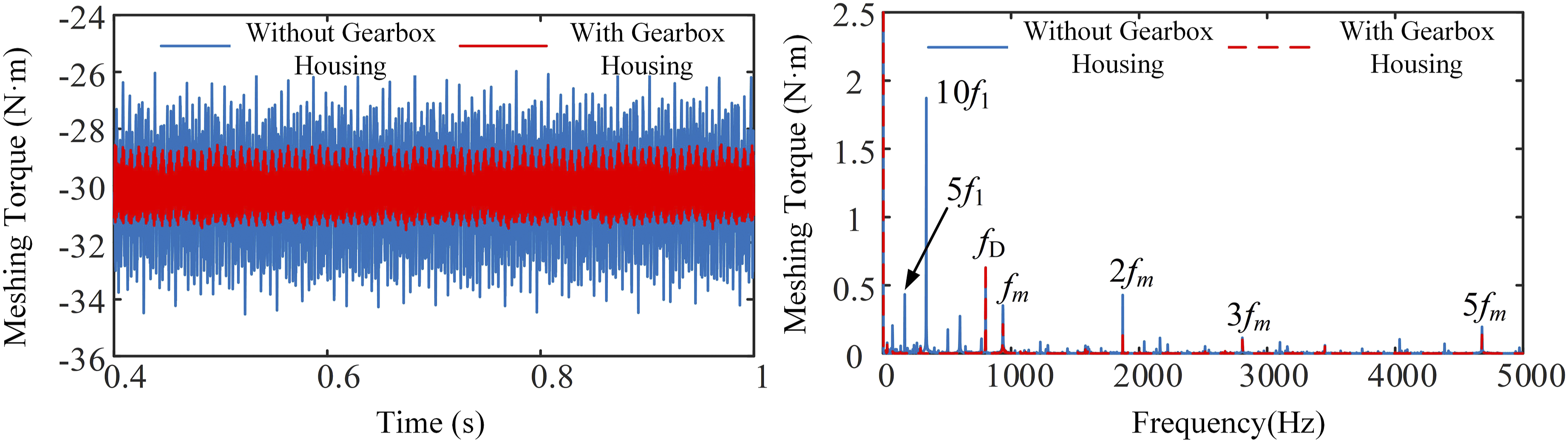
Load-sharing performance is crucial to the quality of planetary transmissions. When all planet gears share the load perfectly uniformly, the load-sharing coefficient is 1; a larger coefficient indicates more uneven load distribution. After coupling the gearbox housing, the load-sharing coefficients for both the external and internal mesh pairs decrease, indicating that the flexible housing can reduce the non-uniformity of the load distribution. After coupling the gearbox housing, the flexible housing not only absorbs vibration energy but also improves the support conditions for the ring gear and planet carrier, alleviating off-center loading. Therefore, the system’s load distribution becomes more uniform after coupling the housing.
4.2. Experimental study: Effect of operating conditions on dynamic characteristics
The simulation analysis focused on internal parameters, whereas this section, using the experimental test rig, focuses on the external operating condition changes commonly encountered in actual system operation. To further explore the dynamic response characteristics of the system under complex operating conditions, experiments with variable speed and variable load were conducted to analyze the patterns of vibration change.
4.2.1. Effect of different input speeds
The excitation current of the magnetic powder brake was adjusted to set the mean load torque at 50 N·m. Simultaneously, the SRM speed was controlled to increase gradually from 0 r/min to the rated speed of 2000 r/min in steps of 100 r/min. Signals were collected after the system reached stable operation at each speed.
As shown in Figure 12, at lower speeds, the peak-to-peak vibration acceleration at the motor bearing measurement point is greater than at the three planetary gearbox measurement points, indicating that the SRM vibration is more severe at this time. As the input speed increases, the peak-to-peak vibration acceleration at the three planetary gearbox measurement points increases rapidly, while the peak-to-peak vibration acceleration at the motor bearing point increases rapidly before 500 r/min and changes very little after 500 r/min. When the load torque of the SRM electric drive system is constant and the speed is high, the change in speed has a greater impact on the vibration of the gear section. Effect of input speed on vibration acceleration.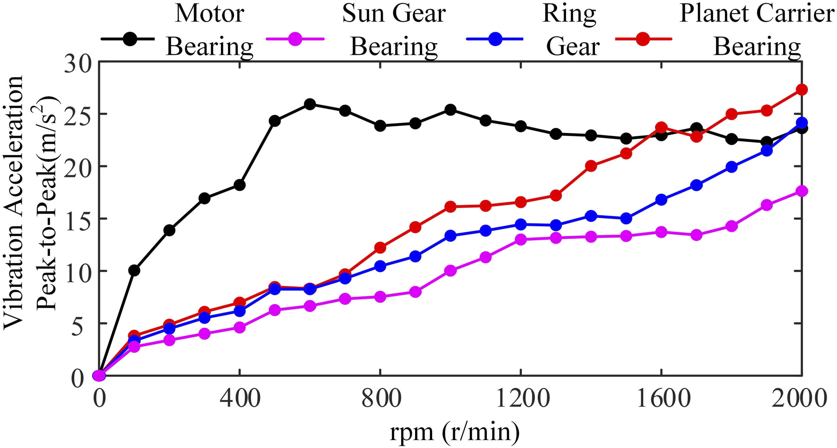
Specifically, Figure 13 shows the vibration acceleration at the sun gear bearing measurement point at different speeds. As the speed increases, the vibration of the sun gear bearing becomes more intense. The main frequency components at the sun gear bearing measurement point are the gear meshing frequency f
m
, the input shaft rotational frequency f1, the power supply switching frequency f
D
, and harmonics of these frequencies. As the harmonic order n increases, the amplitude of nf
m
gradually decreases, indicating that high-order meshing frequencies have a smaller impact on the sun gear bearing vibration. Furthermore, the amplitude of the gear meshing frequency f
m
increases with increasing speed, while the proportion of the power supply switching frequency f
D
and high-order phase current frequencies (49f
ph
) gradually decreases. This phenomenon indicates that as speed increases, the influence of the gear meshing frequency f
m
and its harmonics nf
m
on the sun gear bearing vibration gradually strengthens. The trends for the ring gear and planet carrier bearing are consistent with that of the sun gear bearing. Vibration acceleration at the sun gear bearing measurement point.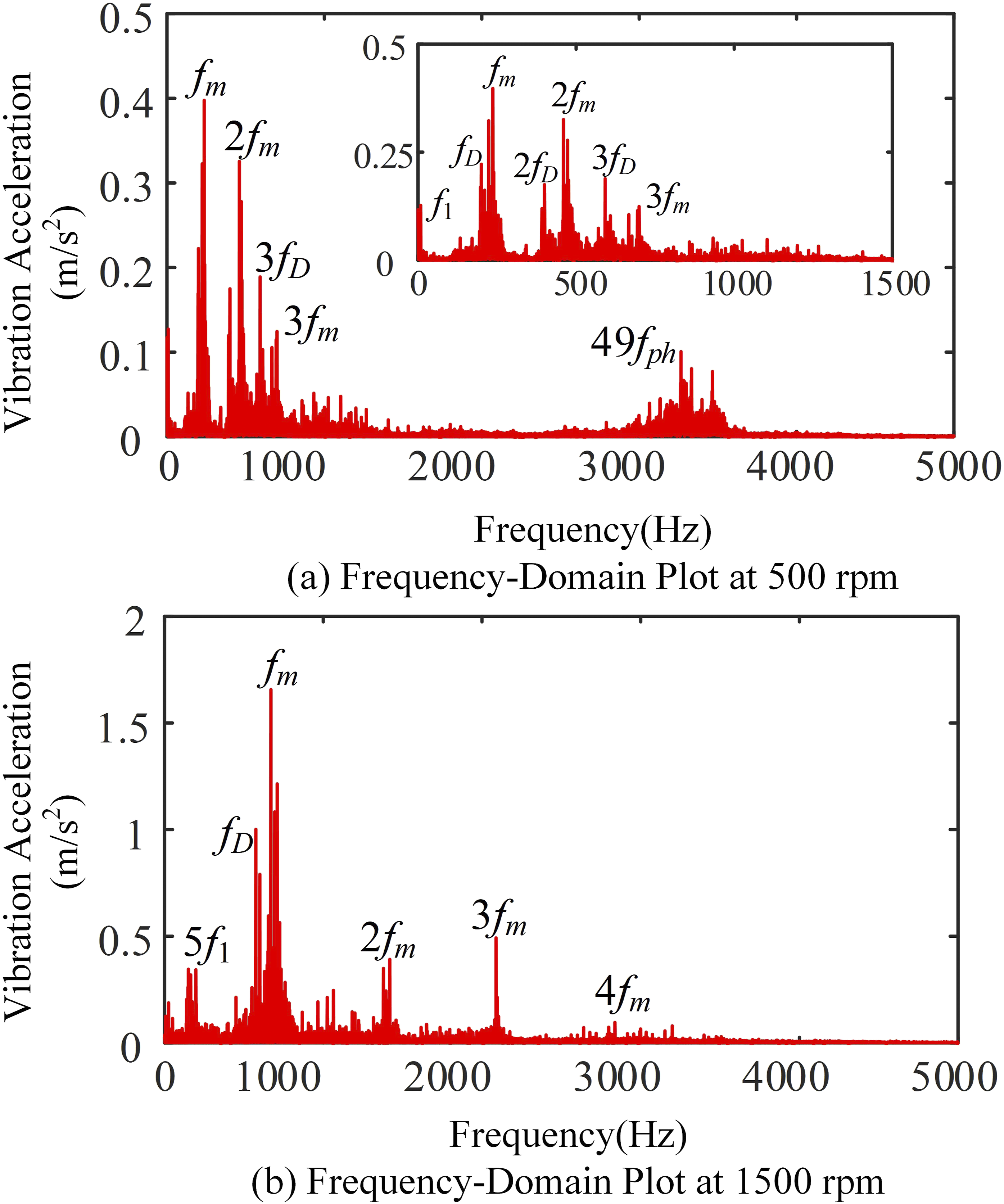
4.2.2. Effect of different load torques
The SRM speed was controlled at 1000 r/min and held constant. Simultaneously, the excitation current of the magnetic powder brake was adjusted to gradually increase the load torque from 10 N·m to 100 N·m. Signals were collected from each measurement point after the system reached stable operation at each state.
As shown in Figure 14, the change in load torque has a significant effect on the vibration acceleration of the SRM electric drive system. As the load torque increases, the peak-to-peak vibration acceleration at all measurement points gradually increases. The rate of increase at the motor bearing measurement point is greater than that at the three planetary gearbox measurement points. This indicates that when the electric drive system’s speed is constant, the change in load torque has a greater impact on the vibration of the motor section. Effect of load on vibration acceleration.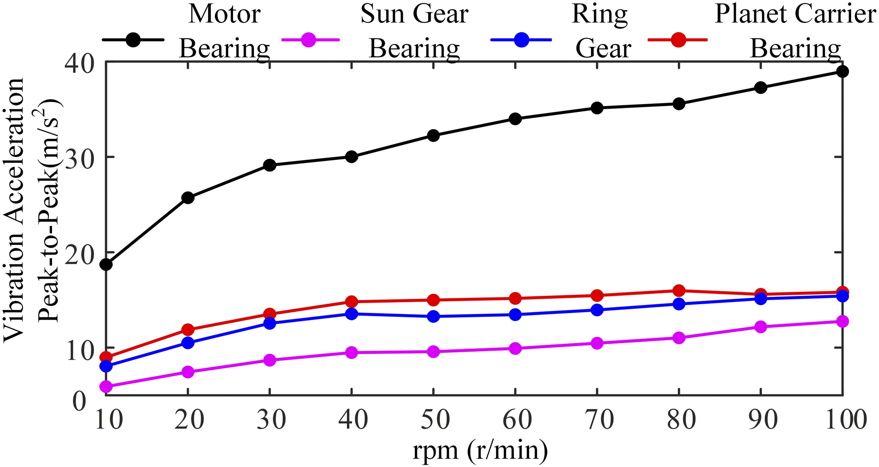
Figure 15 shows the vibration acceleration at the motor gear bearing measurement point under different load torques. The time-domain plots show that after the load torque increases, the vibration acceleration amplitude also increases. The frequency-domain plots show that the main frequency components at the sun gear bearing measurement point are the gear meshing frequency f
m
and its harmonics nf
m
, the power supply switching frequency f
D
, and harmonics of the phase current frequency nf
ph
(22f
ph
, 29f
ph
). Vibration acceleration at the motor gear bearing measurement point.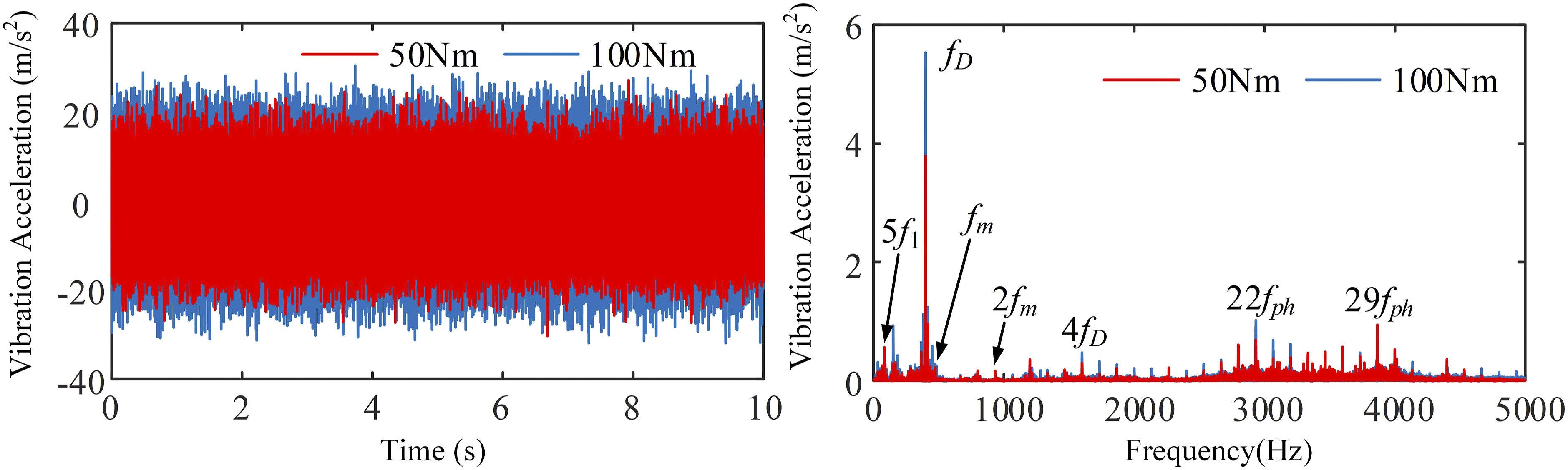
Although gear meshing frequency is the main excitation source of gearbox vibration, it remains nearly constant owing to unchanged SRM speed. The aggravated vibration relies on typical electromechanical coupling transmission characteristics. Increased load torque enlarges SRM phase current and strengthens electromagnetic torque ripple, which induces intense electromagnetic vibration of the motor. As the motor rotor shaft is rigidly connected with the gearbox input shaft, motor electromagnetic vibration is directly transmitted to the sun gear bearing along the transmission chain. Meanwhile, structural damping and gear meshing damping continuously dissipate vibration energy during transmission. Accordingly, vibration changes of the inner gear ring and planetary carrier are relatively mild.
5. Conclusion
This paper established an electromechanical coupling dynamic model for the SRM-planetary gear electric drive system, which accounts for core magnetic saturation, component flexibility, manufacturing errors, and non-inertial frame effects, and its correctness was verified through experiments. The main conclusions are as follows: (1) The established electromechanical coupling dynamic model can accurately reflect the system’s dynamic characteristics. Under steady-state operating conditions, the simulation and experimental phase current RMS value error is 6.32%, and the vibration acceleration RMS value errors at all key measurement points are within 13.4%, verifying the high accuracy of the model in steady-state analysis. (2) Simulation analysis based on the validated model for key internal factors shows that: SRM torque ripple significantly increases the fluctuation of gear meshing torque. Among manufacturing and installation errors, motor rotor dynamic eccentricity and gear pitch error have the most significant impact on the system’s vibration characteristics and should be prioritized for control. A flexible gearbox housing can effectively absorb vibration and improve load-sharing performance. (3) Experiments revealed the system’s vibration response characteristics under real-world dynamic operating conditions: When the load is constant, a change in speed primarily affects the vibration of the gear system. When the speed is constant, a change in load primarily affects the electromagnetic vibration of the motor system.
Footnotes
Funding
The authors disclosed receipt of the following financial support for the research, authorship, and/or publication of this article: This work was supported by the Open Fund Project of Joint International Research Laboratory of Intelligent Manufacturing & Control of Key Parts for Energy-efficient & New Energy Vehicles, Ministry of Education (Chongqing University of Technology) (No. 2024JIRLIMC01) and Chongqing High Level Research and Innovation Platform for University (No. 2022PTTS002), and the Science and Technology Research Program of Chongqing Municipal Education Commission (Grant No.: KJZD-M202503102).
Declaration of conflicting interests
The authors declared no potential conflicts of interest with respect to the research, authorship, and/or publication of this article.