
Abstract
This study focuses on designing electric powertrain and navigation systems for an autonomous electric vehicle under various trajectory conditions. The powertrain is configured as an RWD–4 × 2 system, powered by a 400 (V) lithium battery pack, delivering approximately 65 (kW) to a PMSM. The first novelty of this study lies in the design of the navigation system based on a Fuzzy Logic Controller (FLC) for specific trajectory scenarios, utilizing seven levels of lateral error ey and heading angle error eϕ to determine the steering angle Δ. The second novelty is the design of a 600 (V) DC-DC boost converter control system using a cascaded Adaptive Sliding-Mode Control (ASMC) approach for both current and voltage regulation. The results show that the vehicle can accelerate from 0 to 40 (km/h) in under 3 (s), while the ASMC-based control of the DC-DC boost converter ensures that the output voltage reaches 600 (V) within 0.17 (s), achieving nearly 50% faster response compared to a passive system and maintaining stability throughout the acceleration process. The navigation system maintains the lateral tracking error below 1.2 (m) using FLC with triangle membership functions and 3.3 (m) using FLC with trapezoid functions.
1. Introduction
The development of dynamic models to analyze vehicle behavior and navigation control methods for autonomous vehicles has attracted significant research interest (Dai et al., 2025; Reza, 2008). The research group led by Rachid Alika developed an improved super-twisting sliding-mode control system by integrating a fuzzy logic system to regulate the longitudinal motion of autonomous vehicles; this system was compared with a Neural Network-Based Non-singular Terminal Sliding-Mode controller, and the results demonstrated high performance and robustness under various operating conditions (Rachid et al., 2024). The study by Yasser Bin Salamah designed a robust Sliding-Mode Control system for trajectory tracking of tractor–trailer vehicles during reverse motion; the results showed that the proposed system effectively addressed the inherent control difficulties in reversing under different operating scenarios (Yasser, 2023). The research group of Nural Mammadov applied a Model Predictive Control (MPC) approach to trajectory tracking of autonomous vehicles based on a single-track dynamic model with constant longitudinal velocity; the results, compared with a PI controller, indicated clear performance improvements (Nural and Ibrahim, 2025). The research group led by Xiang Yin proposed the design and experimental validation of an automatic navigation system for agricultural tractors by controlling spatial positioning using RTX service from Trimble; the results showed effective straight-line tracking with a maximum deviation below 7 cm and RMS error below 5 cm (Xiang et al., 2020). The research group of Alireza Hosseinnajad proposed a Fixed-Time Convergent controller by integrating the advantages of the Stanley Controller and Pure Pursuit Controller for lateral vehicle control; the results, compared with conventional methods such as LQR and PID, demonstrated significant effectiveness (Alireza et al., 2025a). The research group of Mustafa Hamid Al-Jumaili proposed a motion control system for autonomous vehicles using a combination of Model Predictive Control and Stanley Controller; the system was evaluated on both straight and curved roads and compared with other control methods (Mustafa and Yasa, 2024). Finally, the research group of Manbok Park proposed a Static Output Feedback (SOF) control approach to estimate difficult-to-measure state variables in vehicle dynamic models, such as lateral velocity and tire slip angle; this system, developed based on LQR and MPC frameworks, demonstrated the ability to overcome the limitations of full-state feedback control methods (Manbok and Seongjin, 2025).
Electric vehicle powertrain system models have long been studied, applied, and generalized into the most common configurations (Mehrdad et al., 2018). The research group of Md Rakibul Karim Akanda provided an overview of the most common EV architectures that have significantly transformed the electric vehicle industry (Md and Tyrese, 2025). The research group of Pothuraju Indu Sree reviewed several typical control algorithms applied to electric motors and powertrain systems, such as DOC and IFOC, where the control process requires timely estimation of vehicle states (Pothuraju and Reddy, 2026). The research group of Simon Fekadeamlak Gebremariam conducted a comparative study on the performance of PMSM motors against other types such as BLDCM, IM, and SRM; the results showed that PMSM exhibits higher torque density efficiency compared to BLDCM, SRM, and IM by 29%, 88%, and 200%, respectively (Simon and Tebeje, 2023). The research group of Stefan Lageweg compared the dynamic characteristics of electric powertrains using PMSM motors and internal combustion engine (ICE) powertrains on the Mercedes-Benz EQA 250+ and Audi A3 8V 35 TFSI, thereby drawing conclusions on the flexibility of each system under varying load conditions in practice (Stefan and Pawel, 2026). The research group of Shaobo Wen developed a full-vehicle dynamic simulation model incorporating the effects of brake pedal, accelerator pedal, and gear shift signals under QC/T759 operating conditions, which serves as an input model for the vehicle’s electrical control system using PCAN-Explore5 software (Shaobo et al., 2026). The research group of G. Ramesh proposed a neural network (NN)-driven efficiency optimization strategy for PMSM motors in electric vehicles instead of the conventional FOC method; the results showed reduced power losses and improved dynamic performance compared to traditional systems (Ramesh et al., 2026). The research group of Deepak Ronanki proposed a novel Direct Torque Control (DTC) method for induction motors (IM) as an alternative to traditional Field-Oriented Control, with validation considering inverter systems, motor dynamics, and vehicle dynamics (Deepak et al., 2013). The research group of Hiep proposed methods to control voltage response under varying load conditions for DC-DC boost converters using PI and SMC approaches, with results indicating that the SMC-based system achieves superior performance (Hiep and Kuo, 2025).
Currently, Vietnam is experiencing rapid growth in the domestic electric vehicle manufacturing industry, with a high demand for research on powertrain systems, electric motors, and batteries for EVs. However, studies on electric powertrain systems and motor control for autonomous electric vehicles remain very limited. Most of the aforementioned studies primarily focus on simulation and evaluation of motor dynamic models in isolation, without integrating them into the overall vehicle dynamic model. In addition, autonomous electric vehicles are still a relatively new topic in Vietnam’s automotive industry; therefore, integrated studies combining electric powertrain models, vehicle dynamic models, and autonomous control systems have not been widely explored. For these reasons, this study is conducted with the aim of proposing design methodologies for control systems of electric powertrain dynamics and vehicle trajectory control systems. The main novelties and contributions of this study are as follows: (1) A navigation system design method based on Fuzzy Logic Control (FLC) using two types of membership functions, namely, Triangle and Trapezoid. The rule base governing the interaction between the levels of lateral error ey and heading angle error eϕ is newly developed. (2) A cascaded control system design method for the DC-DC boost converter, ensuring stable voltage regulation from 400 (V) to 600 (V) while preventing excessive oscillations in the inductor current I
L
.
2. Navigation system design
2.1. Vehicle dynamic model
A 3DOF dynamic model in a single-track configuration describing the vehicle motion in the OXY plane is presented in Figure 1 (Dai et al., 2025). The model represents lateral motion Gy, longitudinal motion Gx, and yaw motion of the vehicle, while pitch and roll dynamics are neglected. The model evaluates the vehicle position in the global coordinate frame G (X
i
,Y
i
) relative to the desired trajectory H (X
ri
,Y
ri
) based on the lateral error ey and heading angle error eϕ. The traction forces generated by the powertrain system are denoted as F
xf
and F
xr
. Vehicle’s trajectory analysis (Dai et al., 2025).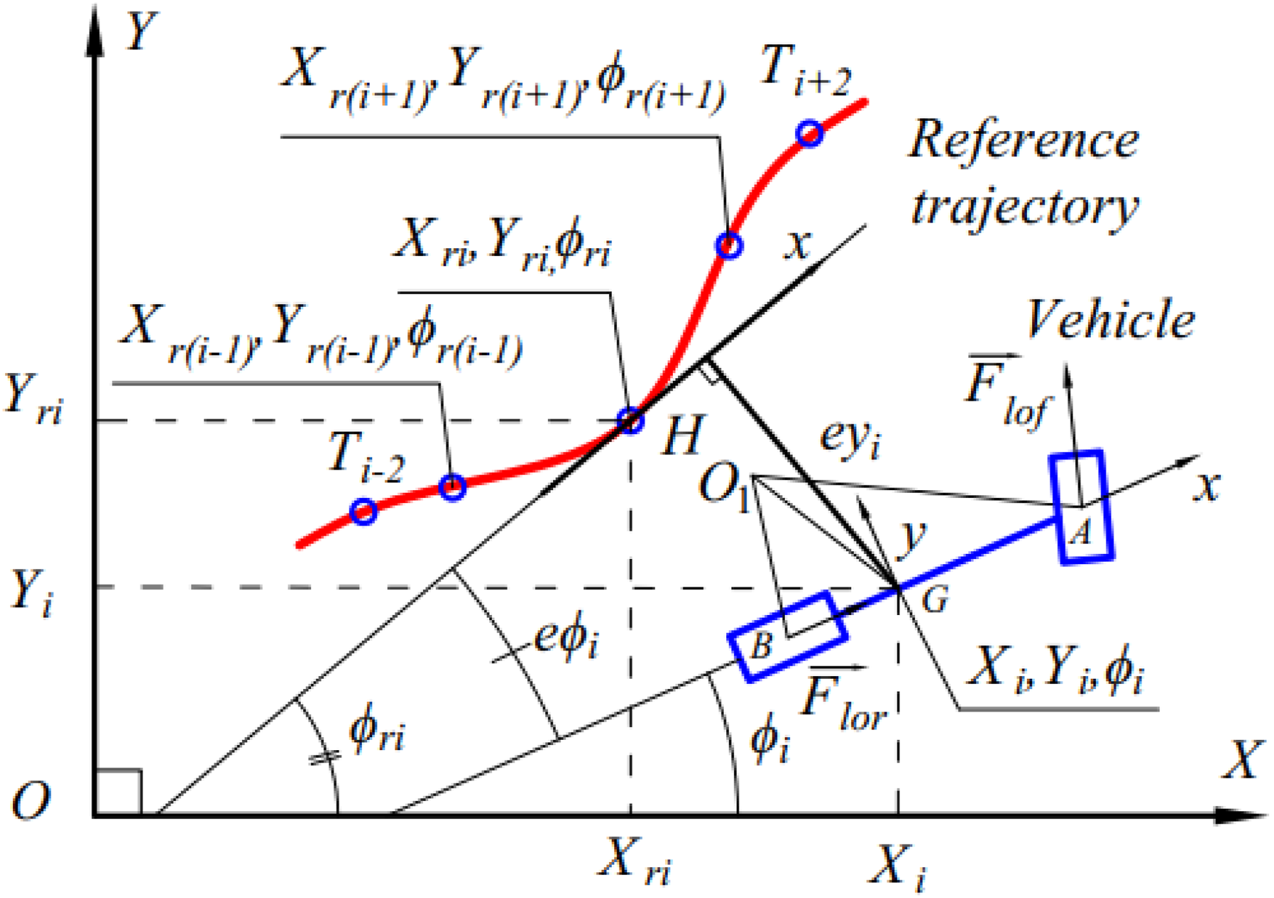
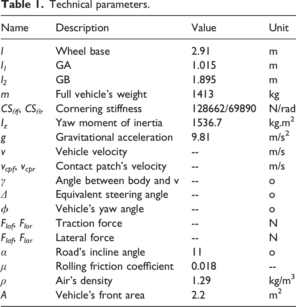
Technical parameters.
Vehicle’s acceleration: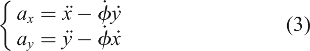
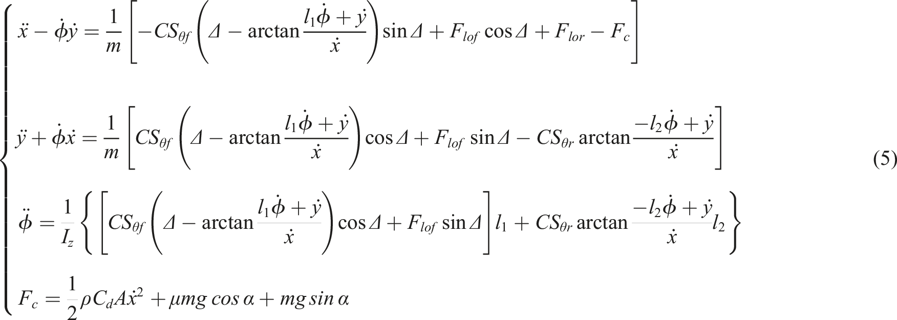
The dynamic equations describing the motion of the vehicle in (4) are obtained by projecting F
lo
and F
la
onto Gx and Gy directions.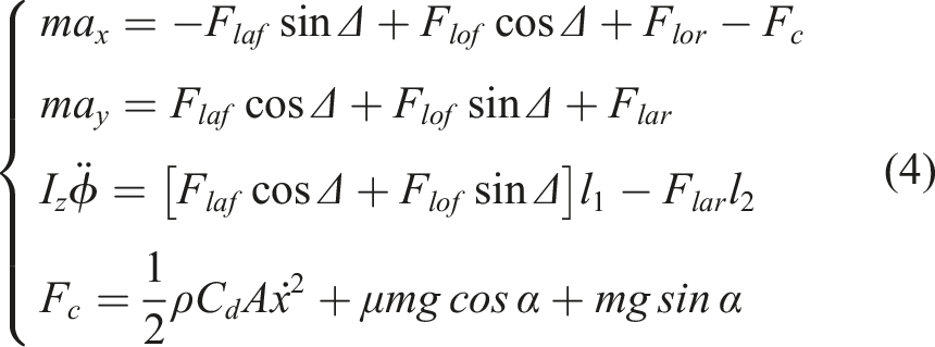
The vehicle coordinates in the XOY plane: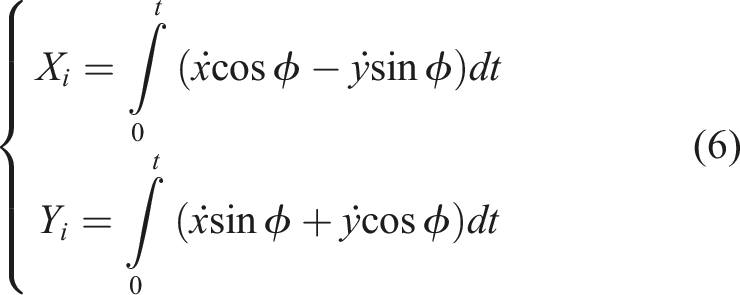
As the vehicle converges to the desired trajectory, the heading angle error eϕ is very small; therefore,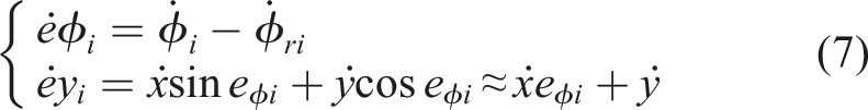
2.2. Navigation system
2.2.1. Fuzzy logic controller – FLC
Most existing studies design navigation systems under the assumption of constant vehicle speed, where longitudinal dynamics are neglected or investigated without fully integrating the powertrain system, including the PMSM, DC-DC boost converter, and their dynamic responses within the overall vehicle system. In this study, a comprehensive integrated model including the PMSM powertrain and DC-DC boost converter is developed. Consequently, the system response differs significantly from existing studies and requires a newly designed set of FLC interaction rules to ensure effective coordination with the PMSM and DC-DC boost converter dynamics.
Rules for controller’s decision.
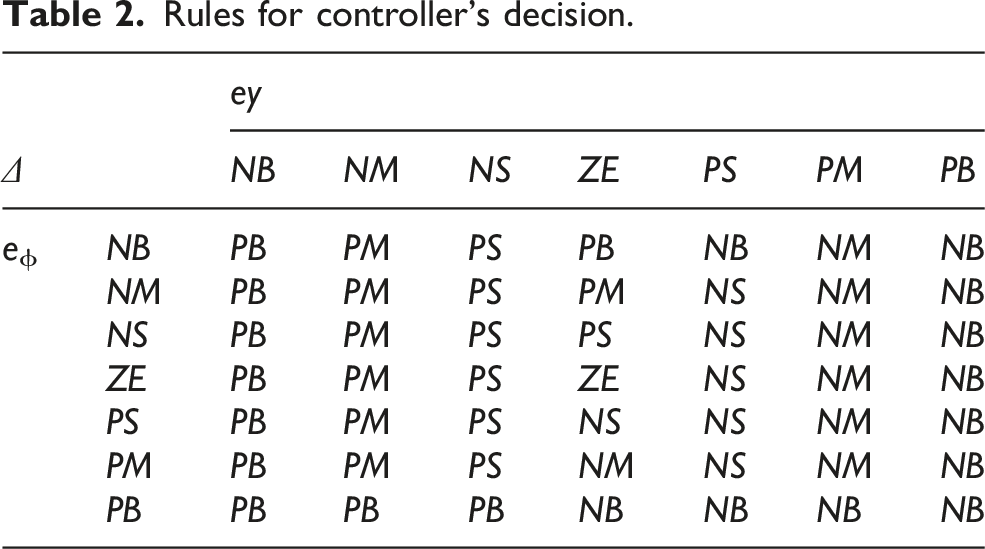
In a practical driving trajectory, the vehicle operating conditions are diverse and complex, including required speed, path curvature, travel distance, disturbances from throttle and braking inputs, as well as the inherent dynamic response of the vehicle. Therefore, to effectively control the vehicle along a predefined trajectory under such conditions, a FLC system is applied for steering angle control. The key advantage of this approach is its ability to define input variables at different levels, thereby determining the system’s final response, which enables flexible adaptation to various scenarios. The study implements the FLC based on the scheme shown in Figure 2(a). FLC and membership function. (a) FLC’s diagram. (b) Relationship of Δ, ey, eφ.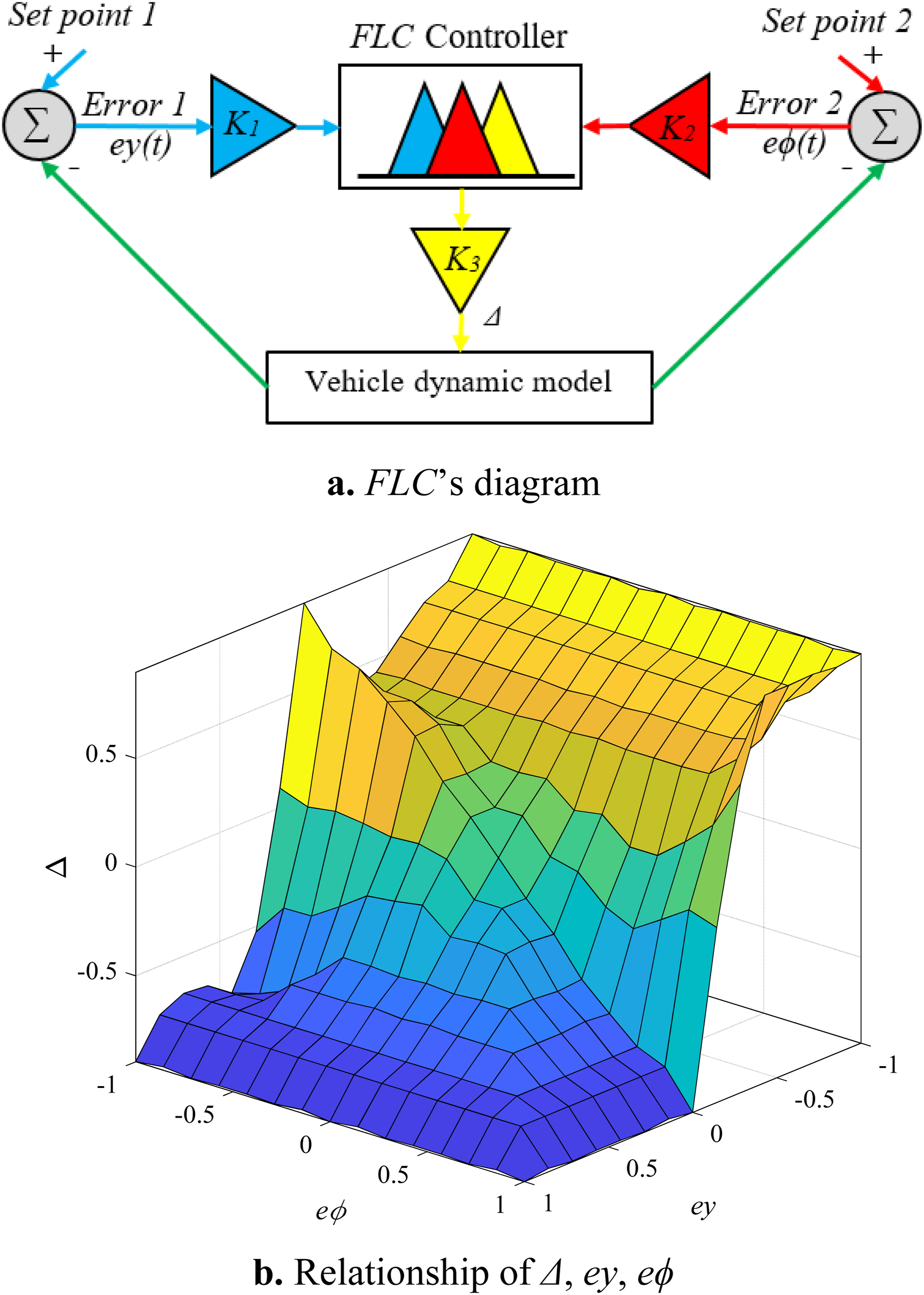
The study employs triangular and trapezoidal membership functions to compare their effectiveness, as shown in Figure 3. All input variables ey, eϕ, and the output Δ are divided into seven levels, including NB (Negative Big), NM (Negative Medium), NS (Negative Small), ZE (Zero), PS (Positive Small), PM (Positive Medium), and PB (Positive Big). The core of the FLC design process lies in defining the relationship between ey, eϕ and Δ through the construction of membership functions, as presented in Table 2 and Figure 2(b). The rules in Table 2 were mainly derived from expert knowledge and refined through a trial-and-error process. Membership function. (a) Triangular membership function – Trimf. (b) Trapezoidal membership function (Trapmf).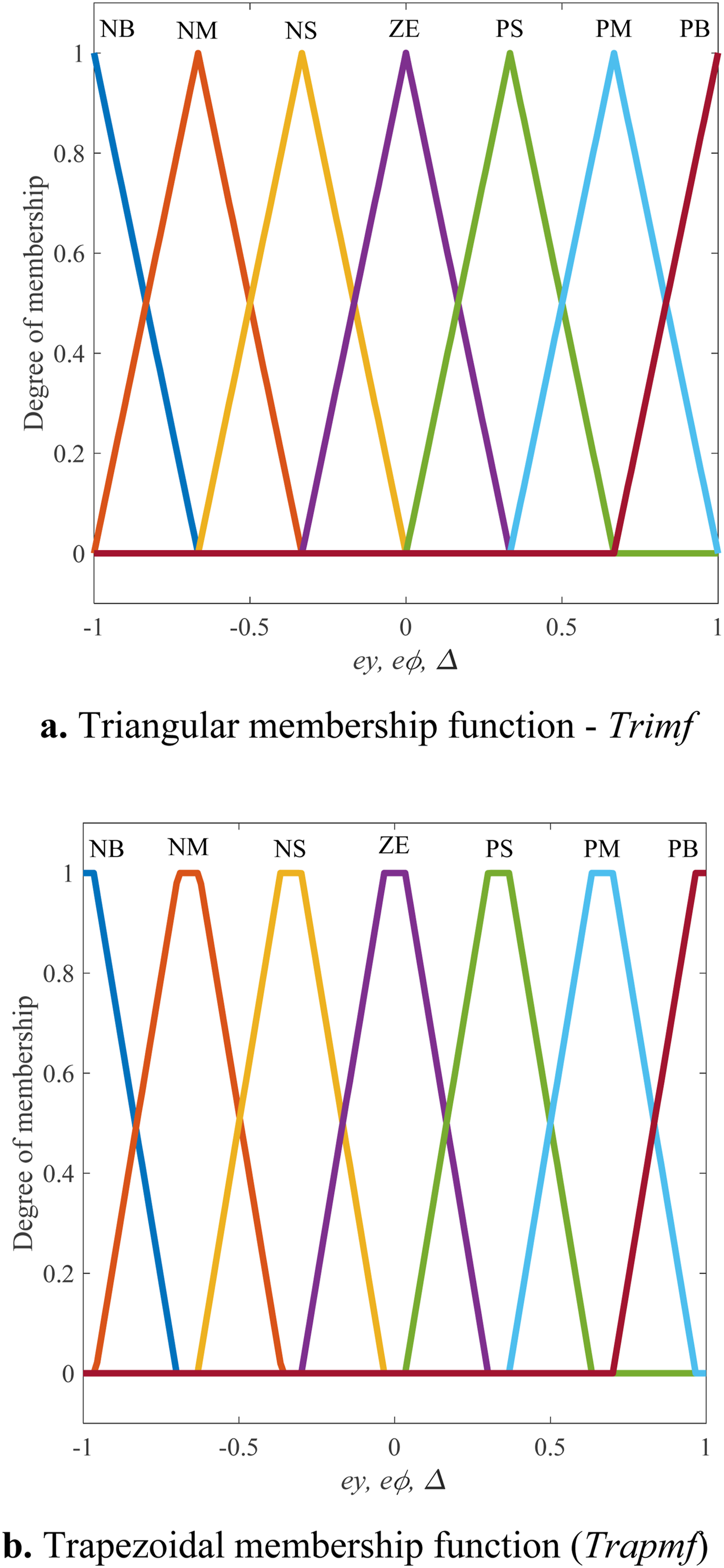
2.2.2. Sliding-mode controller – SMC
The SMC is applied similarly to control Δ. Based on the relationship between ey and eϕ in (7), the sliding surface s according to (8) is defined, (c > 0).
Set:
Therefore,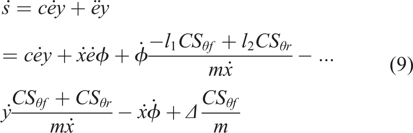
According to reaching law with constant rate: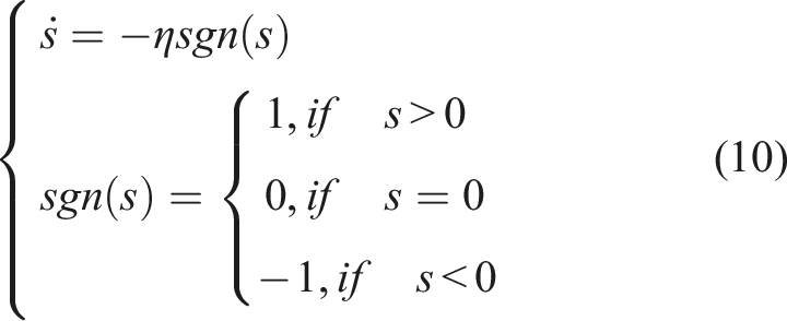
Δ is determined as (11) to satisfy (10). When (10) is satisfied, the sliding surface s in (6) converges to zero, thereby allowing ey and eϕ to approach zero and enabling the vehicle to follow the desired trajectory.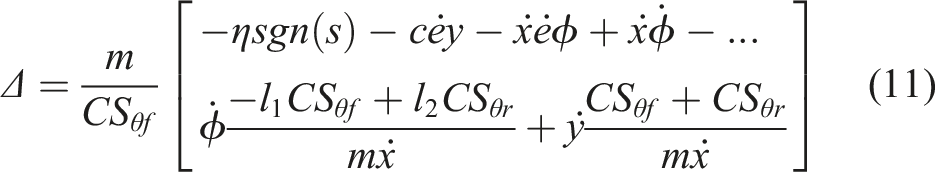
Design the Lyapunov function as (12):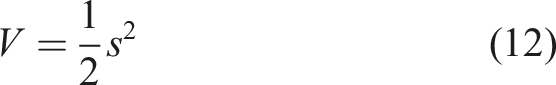
Then,
From
3. EV’s powertrain
The powertrain system is designed based on the schematic shown in Figure 4. This system receives power from a lithium battery to generate torque transmitted to the rear axle, ensuring a target speed of 40 (km/h). The 400 (V) battery is boosted to 600 (V) using a DC-DC boost converter to supply the PMSM. The DC-DC boost converter is responsible for maintaining a stable 600 (V) input voltage to the PMSM under various operating conditions, where the load on the motor continuously varies. The PMSM is continuously controlled by a speed controller through a Field-Oriented Control (FOC) scheme. The speed controller determines the reference voltage applied to the motor based on the actual vehicle speed and the driver’s demand from the accelerator pedal. This voltage is then converted into pulse signals by the Space Vector Modulation (SVM) technique to drive the Voltage Source Inverter (VSI). RWD 4 × 2 EV’s powertrain diagram and simulation. (a) Powertrain’s diagram. (b) Matlab Simulink model for PMSM and DC-DC boost converter.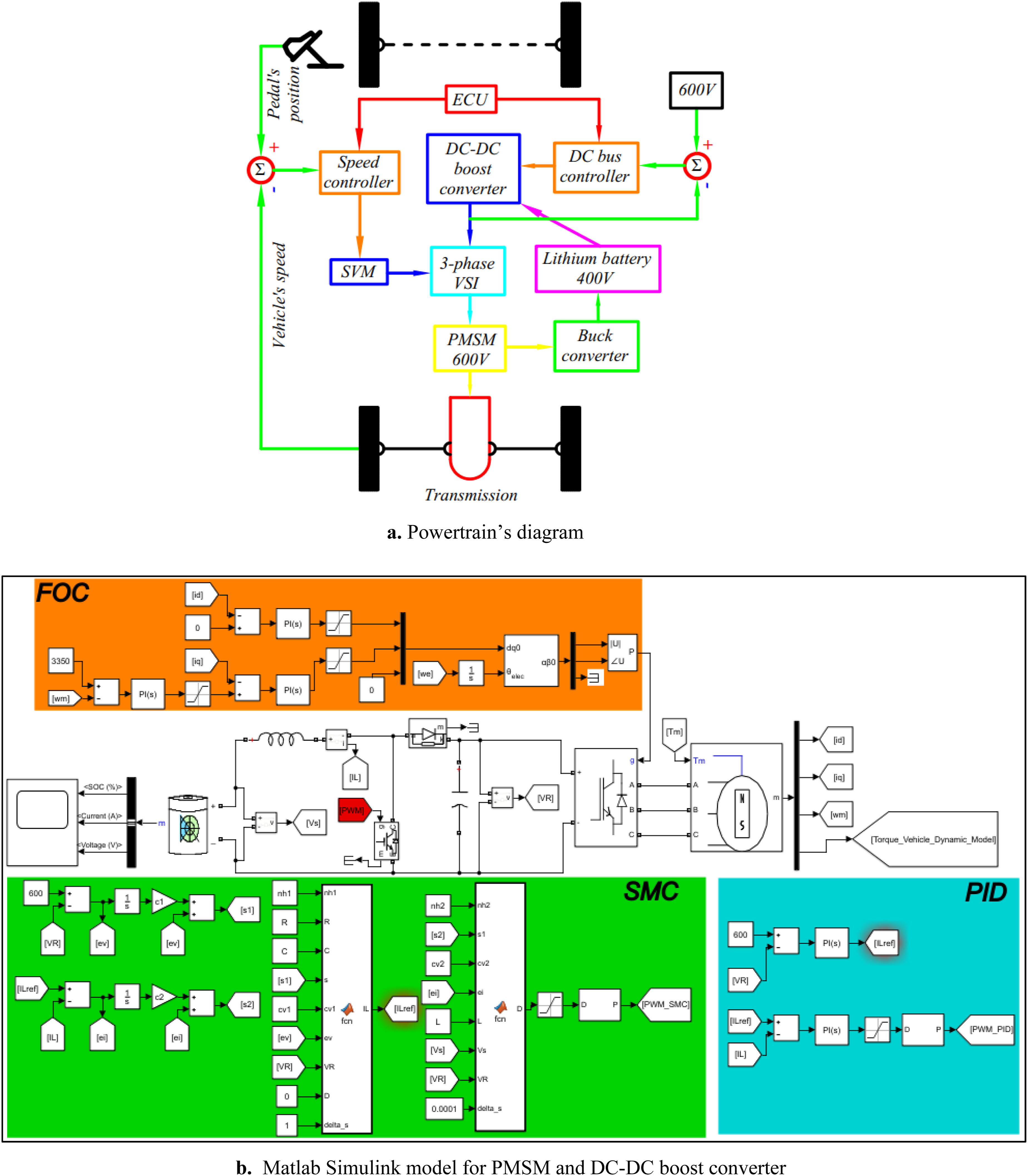
3.1. Permanent magnet synchronous motor – PMSM
The PMSM is widely used as a power source for electric vehicles due to its ability to generate instantaneous maximum torque, reduced wear owing to the absence of brushes, and high power density with a significantly smaller size compared to internal combustion engines (Mehrdad et al., 2018). With three-phase voltage signals from a conventional inverter, direct control of the PMSM is challenging; therefore, engineers have developed a method to transform signals from the abc frame to the dq frame for more effective control, Figure 5(a). This process follows the Park–Clarke transformations (Setty and Chatterjee, 2017). In the dq frame, the current I
d
is used to control the magnetic flux, while I
q
is used to control the electromagnetic torque; since I
d
and I
q
are decoupled, control becomes easier compared to the original frame (Setty and Chatterjee, 2017). However, control in the dq frame remains complex and requires an integrated control structure combining cascaded control, mathematical transformations, and vector control via FOC to simultaneously regulate I
d
, I
q
, and motor speed, as illustrated in Figure 5(b) (Marcel et al., 2022). PMSM and FOC. (a) PMSM. (b) FOC.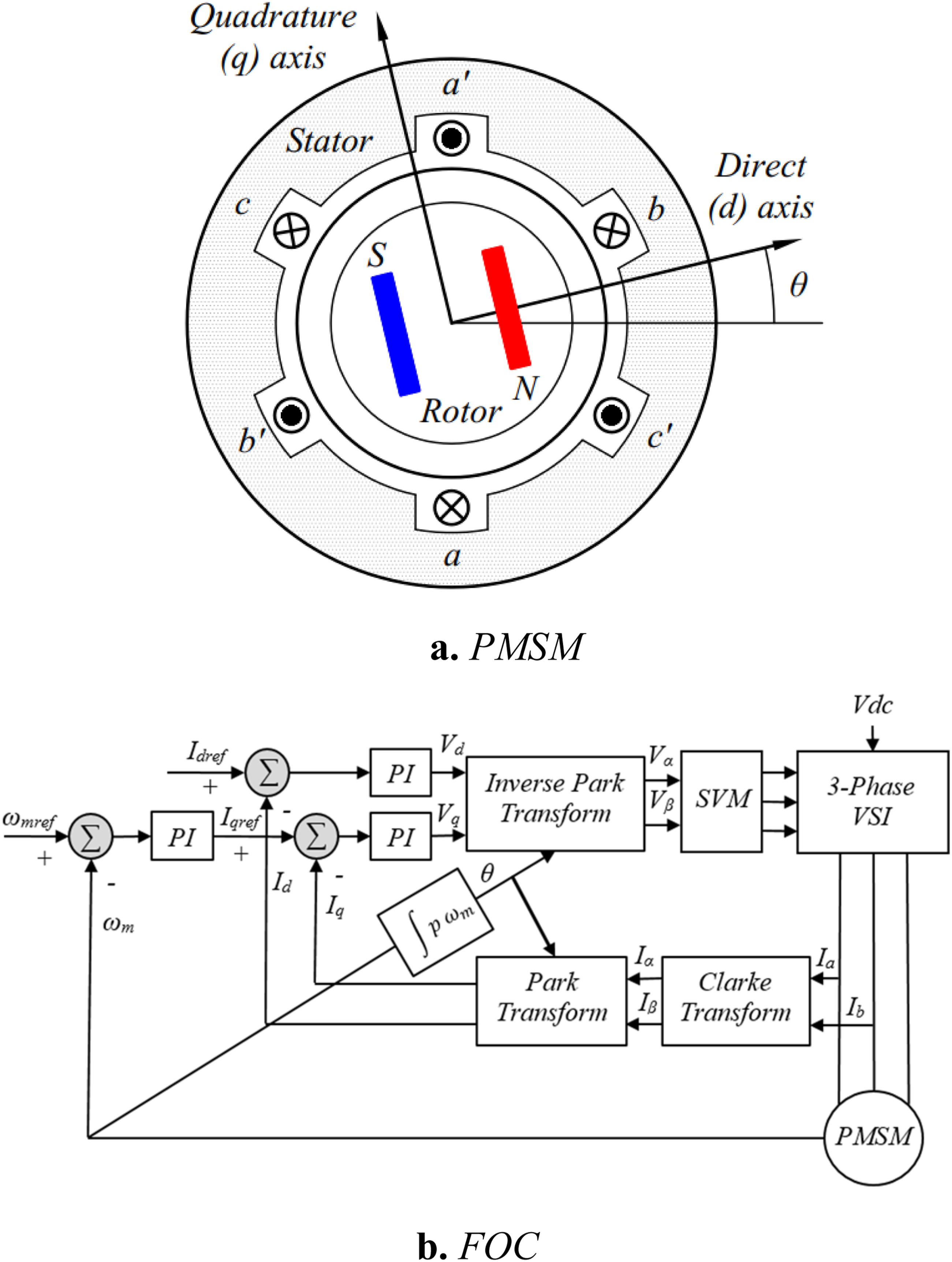
PMSM mathematical model:
Voltage: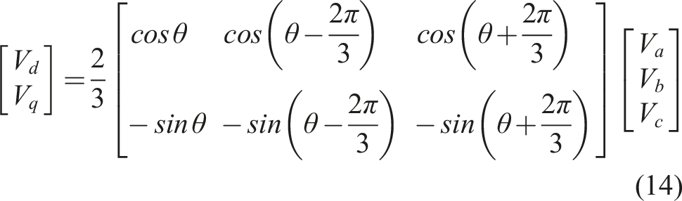
Current: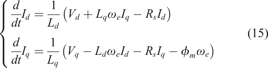
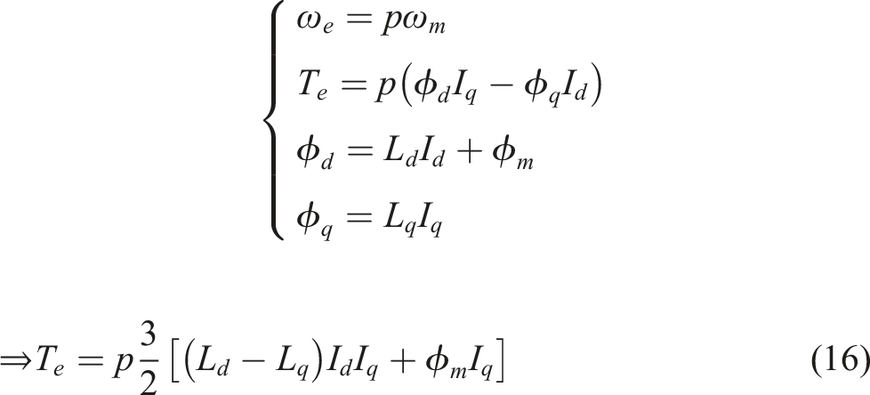
Torque T
e
:
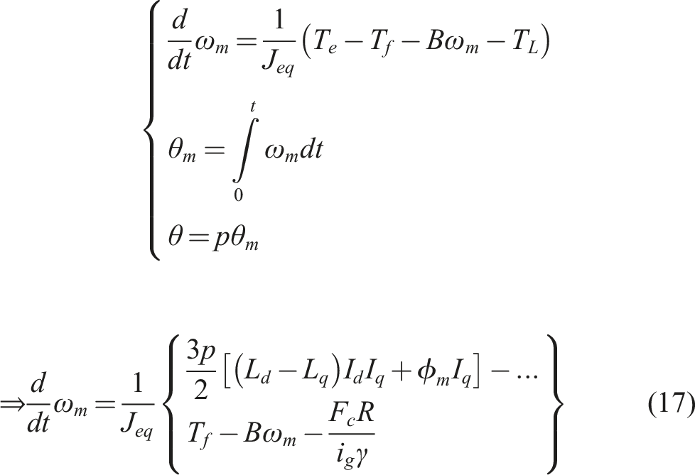
Angular velocity ω
m
:
Load inertia referred to motor shaft J eq :
PMSM’s kinetic energy: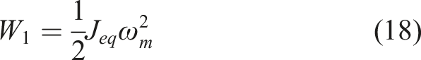
Powertrain’s kinetic energy: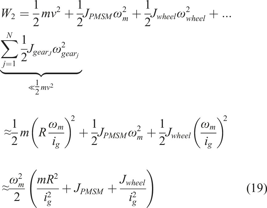
Let W1 = W2, we have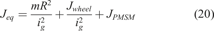
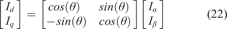
The PI speed controller uses the error between the reference speed ω mref and the measured motor speed ω m to regulate the reference current I qref . The PI current controllers, based on the errors between the reference currents I qref , I dref , and the measured currents I q , I d , generate the required voltage signals V q and V d . These voltage signals are then transformed back through the inverse Park transformation into V α , V β , and fed into the SVM block. The SVM block uses V α , V β to generate switching pulses for the IGBT devices of the three-phase VSI. I q and I d are obtained by measuring I a , I b , I c and transforming them using Clarke and Park transformations as given in (21) and (22).
Clarke transform I
a
, I
b
, I
c
→ I
α
, I
β
: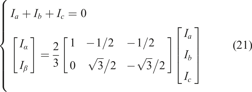
Park transform I
α
, I
β
→ I
d
, I
q
:
Inverse Park transform V
d
, V
q
→ V
α
, V
β
:
PI controller:
The study employs three PI controllers (Dai et al., 2025) to regulate the signals ω m , I d , and I q within the FOC system.
Errors:
Controllers: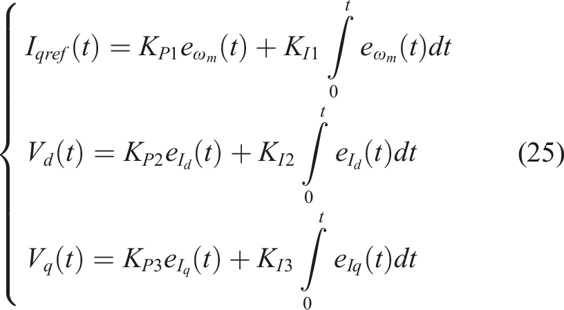
3.2. DC-DC boost converter
The DC-DC boost converter is widely used in EVs to increase the battery voltage versus to a higher level V
R
, ensuring stable and safe motor operation (Ahmad et al., 2023). The boost converter circuit, Figure 6, consists of key components including a voltage source versus (a 400 (V) lithium battery), a high-frequency switching device (IGBT) controlled by a PWM signal with duty cycle D and switching frequency f
s
= 20 (kHz), and an inductor with inductance L (H), as defined in (30), which stores energy in a magnetic field and releases it to boost the voltage through the switching action of the IGBT. The diode D prevents reverse current flow from the output back to the source, while the capacitor with capacitance C (F), as given in (31), is used to filter and smooth the output voltage. The resistor R represents the load of the system (PMSM). DC-DC boost converter and cascade control system.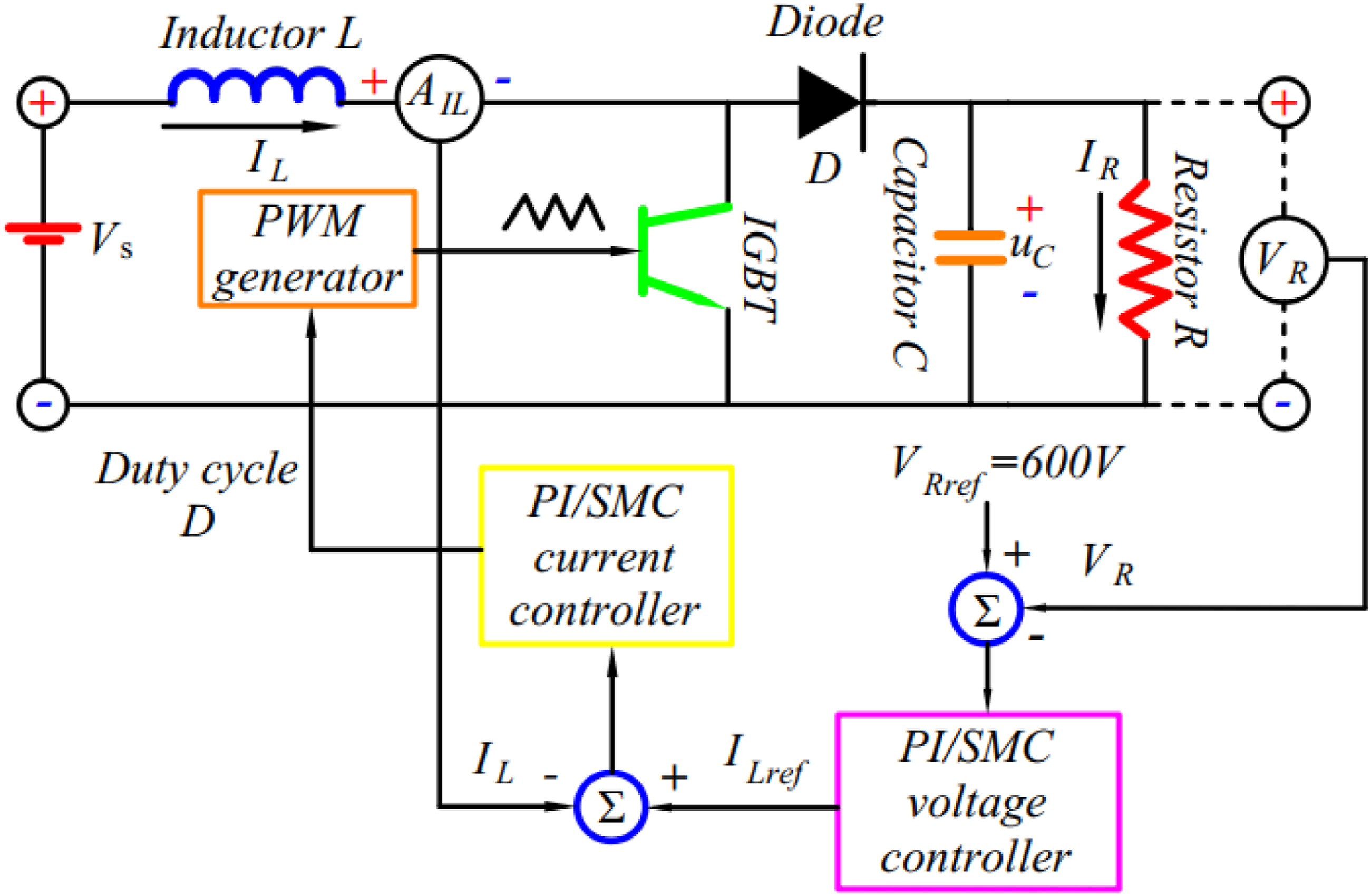
Applying KVL to the entire circuit: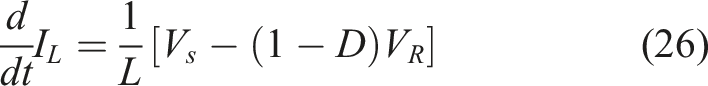
Applying KCL at the capacitor node: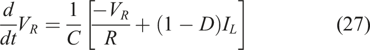
Overall model: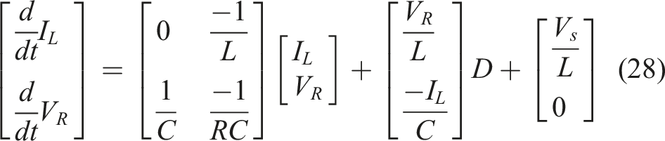
Duty cycle without controller: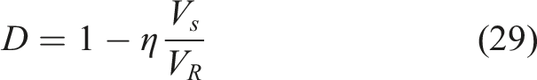
Inductance L: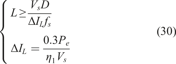
Capacitance C: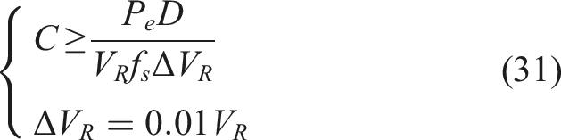
The voltage controller evaluates the voltage error e VR in (32) to determine the required inductor current reference I Lref . The current controller, based on the current error e IL in (32) and the I Lref generated by the voltage controller, determines the required D.
PI controller design:
Errors:
Controllers: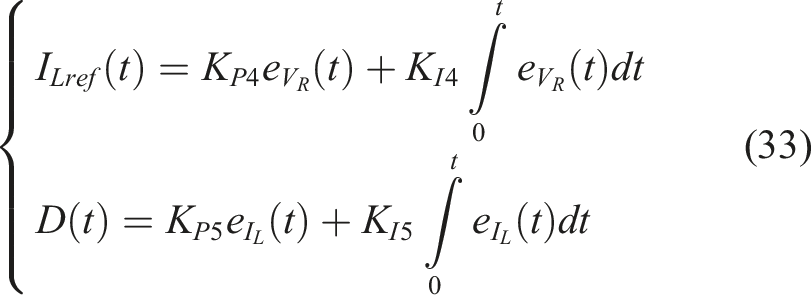
Adaptive robust sliding-mode controller – ASMC design:
Set: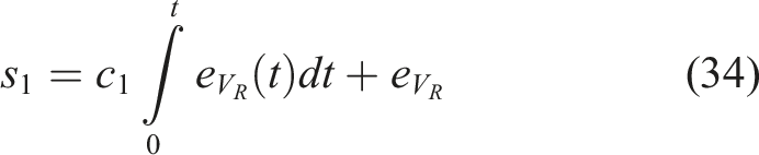
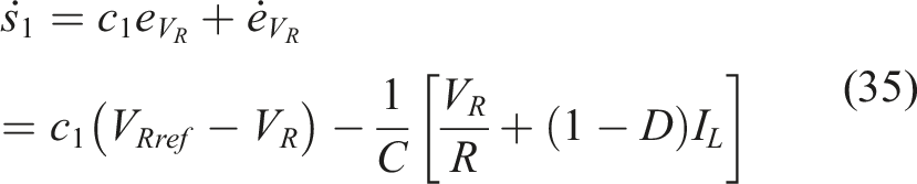
According to exponential reaching law: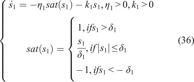
Therefore,
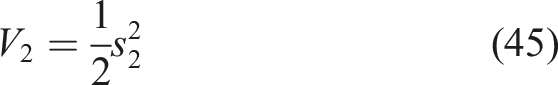
Design the Lyapunov function: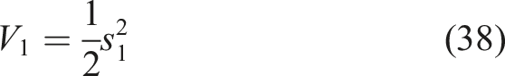
Then,
From
Then,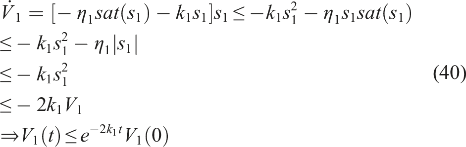
Set: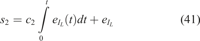
Therefore,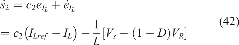
According to exponential reaching law: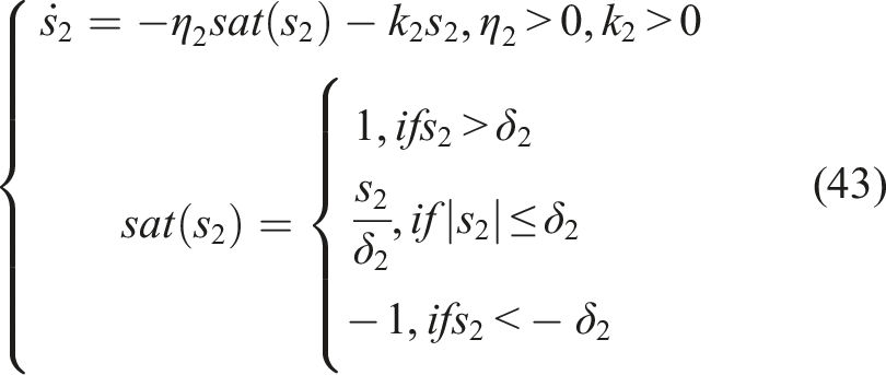
Therefore,
Then,
From
Then,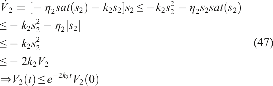
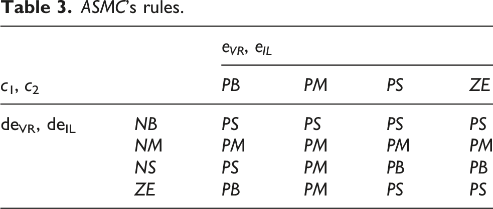
Higher values of c1 and c2 result in faster system responses but also cause stronger oscillations and voltage overshoot V R during the initial stage. However, if c1 and c2 are too small, the stability of V R over the entire operating period cannot be guaranteed. To balance these issues, the study upgrades the SMC controllers in (37) and (44) into an Adaptive Sliding-Mode Controller (ASMC) by applying fuzzy logic to continuously adjust c1 and c2, thereby reducing overshoot and improving system robustness over the entire time domain.
ASMC’s rules.
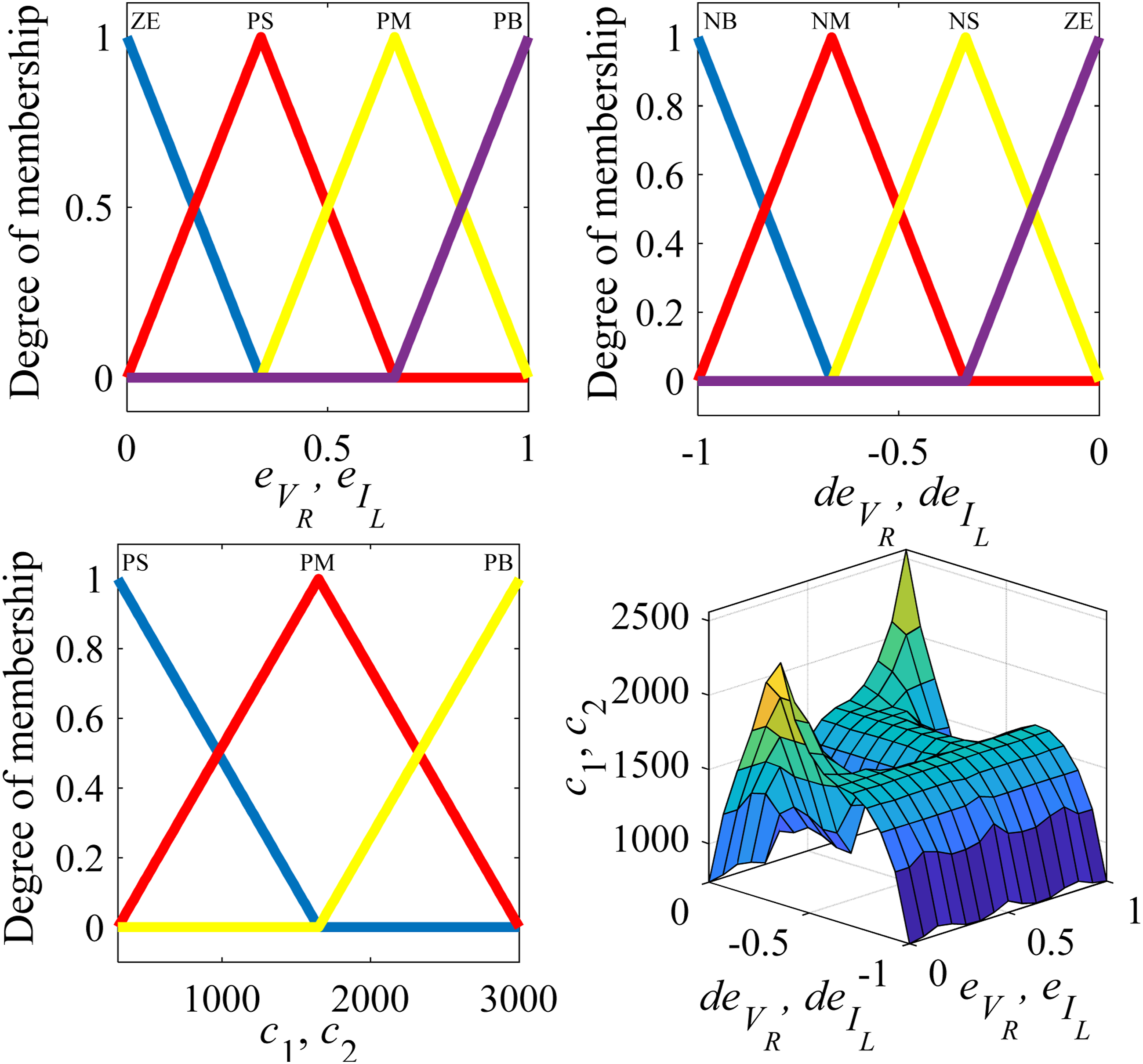
ASMC’s fuzzy logic.
4. Genetic algorithm – GA
GA has long been used in various fields to identify optimal solutions that satisfy predefined objectives and constraints (Dai et al., 2025). In this study, GA is employed to determine the optimal parameters of the controllers in the navigation system, FOC, and DC-DC boost converter. The GA follows an optimization procedure, Figure 8 Table 4, consisting of six steps that mimic the process of natural selection within a population, including operations such as crossover and mutation to progressively evolve toward the best individuals according to the defined objective (Hiep et al., 2023). GA’s operational process (Hiep et al., 2023). Algorithm’s parameters.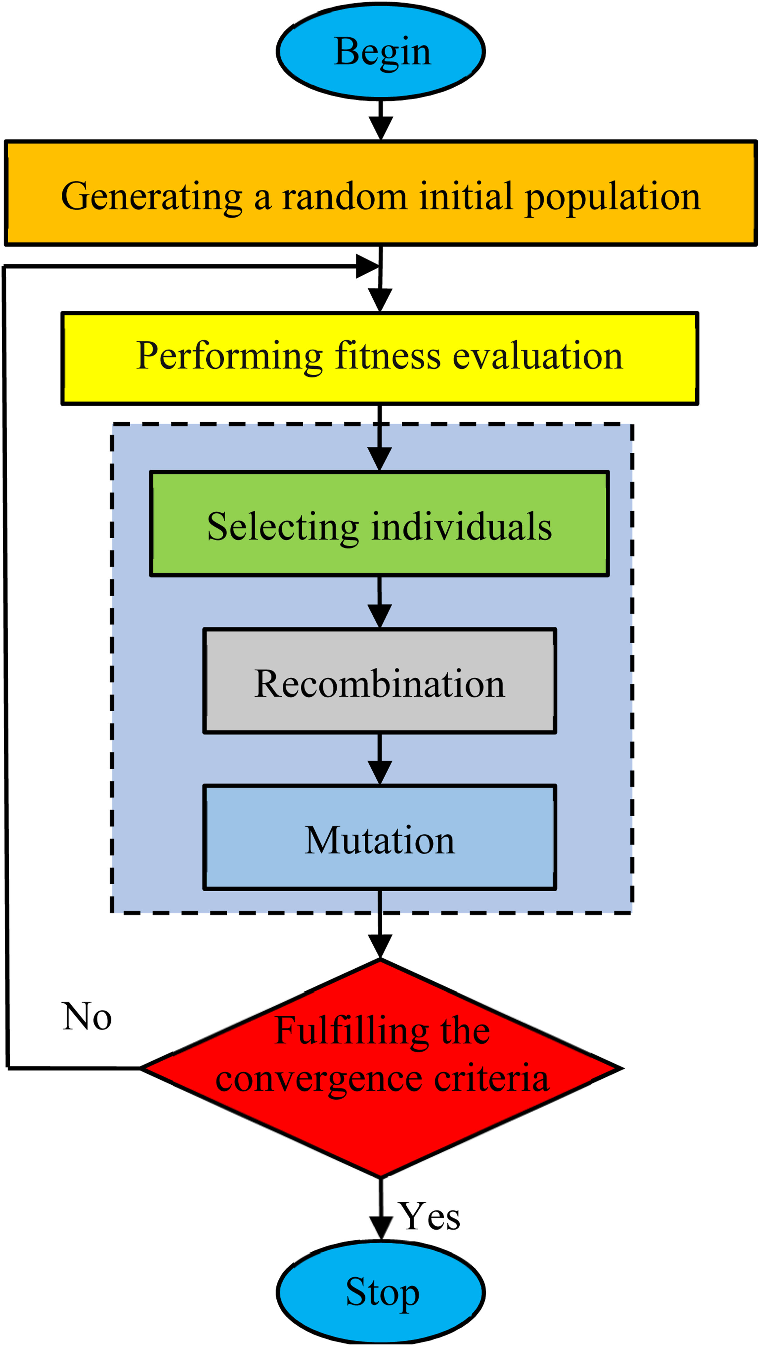
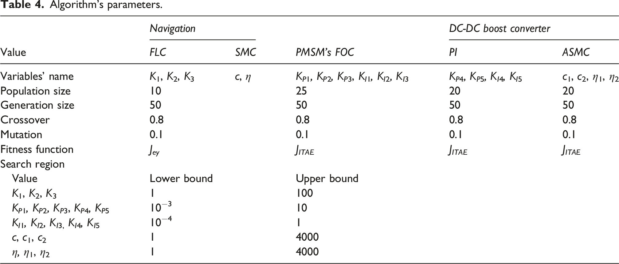
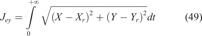
The study employs the ITAE criterion to formulate the objective function J
ITAE
in (48) for the FOC, DC-DC boost converter, and J
ey
in (49) for the navigation system during the optimization process.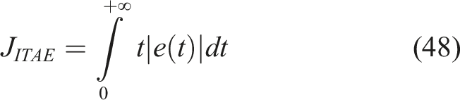
5. Results and discussions
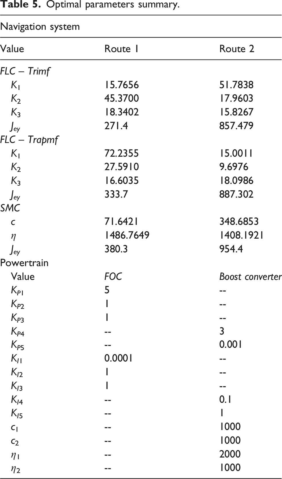
Optimal parameters summary.
The results show that the FLC-trimf, FLC-trapmf, and SMC lateral motion control systems all operate effectively in maintaining vehicle trajectories, Figures 9(a) and (b). For the trajectories in Figure 9, the FLC-trimf achieves 7%–12% and 17%–23% lower distance tracking errors compared with the FLC-trapmf and SMC, respectively, for the trajectories in Figures 9(a) and (b). Both FLC approaches also outperform the SMC, which is known as a robust control method, demonstrating the high effectiveness of the rule base designed in Table 2. EV’s trajectories. (a) Route 01. (b) Route 02.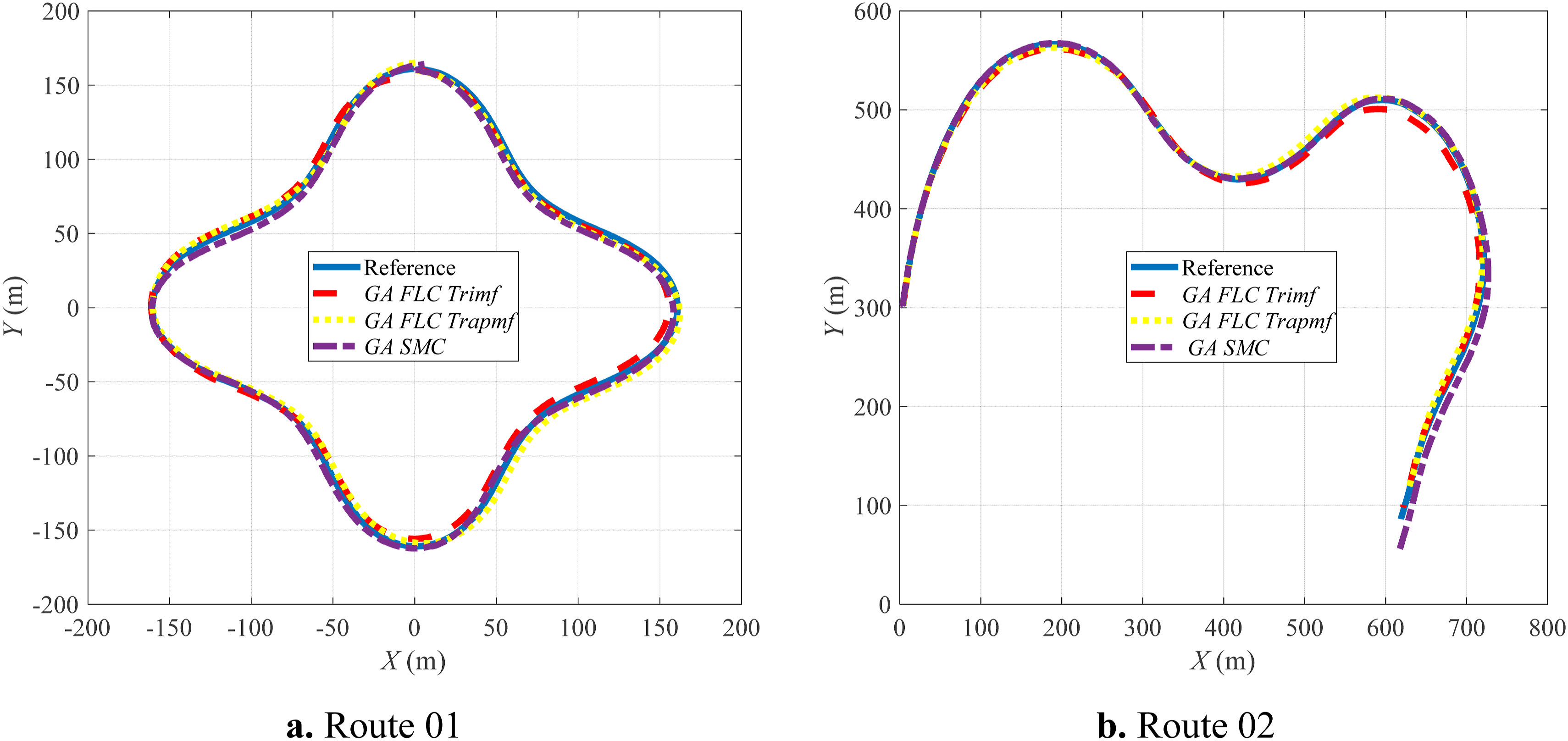
Throughout the required driving trajectories, the output voltage V
R
after the boost converter supplying the PMSM is maintained around 600 (V) with different levels of effectiveness, as shown in Figure 10(a). During the initial transient stage, the PI-controlled boost converter achieves the best voltage stabilization performance with the lowest overshoot (600(V)), compared with the passive system (800(V)), SMC (680(V)), and ASMC (630(V)). The ASMC with fuzzy logic significantly reduces voltage overshoot compared with the conventional SMC and passive system by more than 7% and 21%, respectively. System’s responses. (a) DC-DC boost converter. (b) PMSM and battery.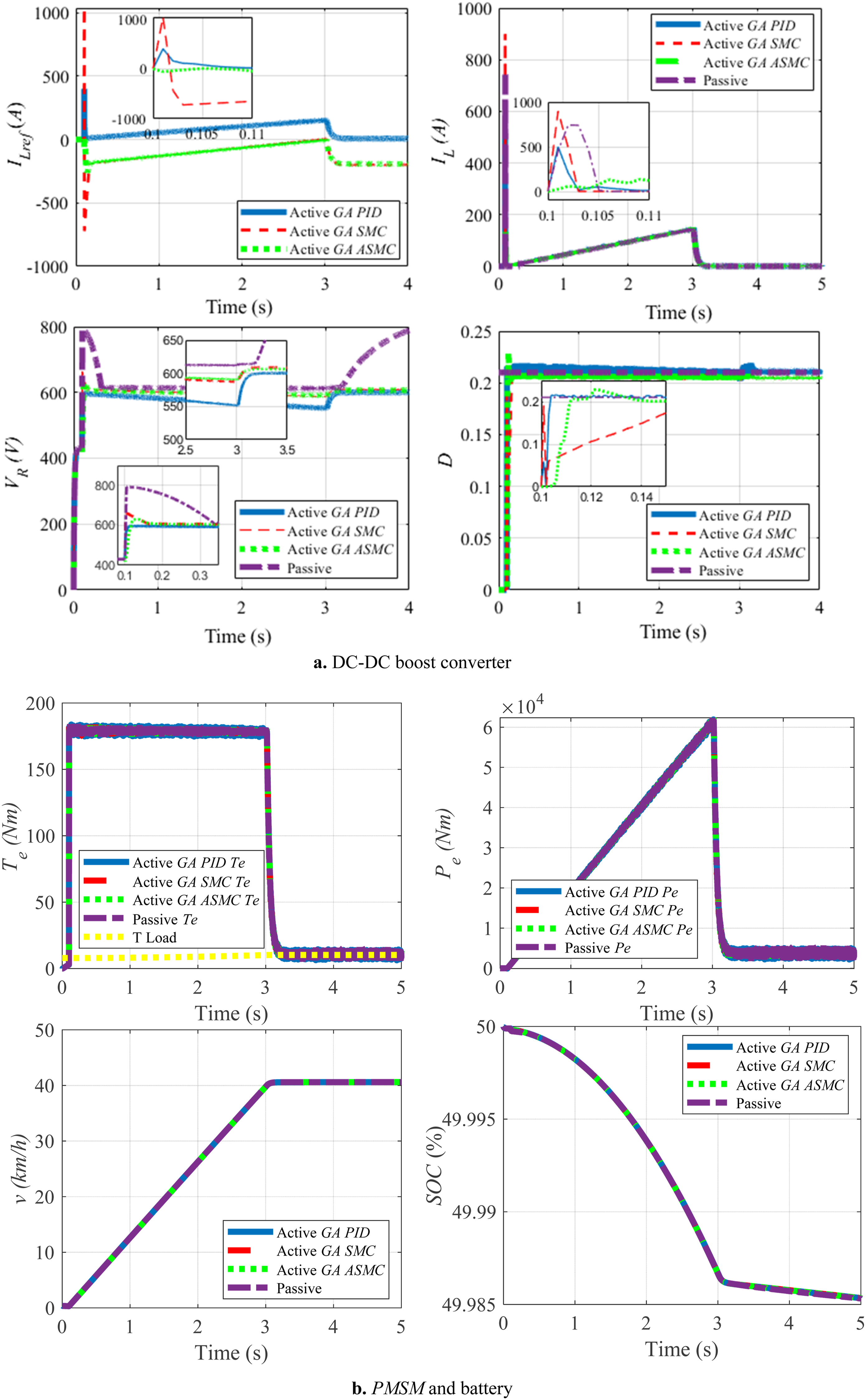
The PI controller stabilizes V R at 600 (V) almost instantaneously, while both ASMC and SMC achieve stabilization within 0.17 (s). However, only the ASMC and SMC systems are able to maintain V R steadily at 600 (V) until the vehicle reaches 40 (km/h), whereas the PI-controlled system shows a noticeable voltage drop below 580 (V). This indicates that the ASMC and SMC systems provide better robustness than the conventional PI controller. The passive system requires 0.35 (s) to reach 600 (V), which is more than 50% slower than ASMC and SMC, and exhibits severe voltage oscillations near the target speed before becoming unstable afterward.
The ASMC also demonstrates superior performance in limiting the current overshoot I L during the initial stage, maintaining I L < 200 (A). In contrast, the PI, passive, and conventional SMC systems produce peak current levels of approximately 500 (A), 750 (A), and 1000 (A), respectively. Therefore, under this operating condition, the ASMC provides the highest practical feasibility by ensuring a safer current level for the electrical components of the system.
Figures 10(a) and 10(b) clearly illustrate the relationship between the PMSM speed response, torque response, and current intensity. Before the vehicle reaches the target speed of 40 (km/h), the FOC-controlled PMSM generates and continuously maintains maximum torque, resulting in a continuously increasing power demand. Meanwhile, the motor voltage is regulated at 600 (V) to ensure operational safety; therefore, the system current I L continuously increases to supply sufficient power to the PMSM. During the rapid acceleration process from 0 to 40 (km/h) within 3 (s), the battery SOC decreases from 50% to 49.985%.
This study is limited by not considering parameter uncertainties, which may be addressed in future work similarly to the approaches in Alireza et al. (2024, 2025b).
6. Conclusions
The study focuses on developing a comprehensive simulation model for the control systems of the powertrain and navigation of an autonomous electric vehicle. In particular, the powertrain system includes components such as the boost converter and PMSM, which are controlled through an integrated structure of multiple control subsystems. The contributions of this study include the following: * A navigation system design method based on FLC using two types of membership functions, namely, Triangular and Trapezoidal. The rule base governing the interaction between the levels of lateral error ey and heading angle error eϕ is newly developed. * A cascaded control design method for the DC-DC boost converter, ensuring a stable voltage 600 (V) while limiting excessive oscillations in the inductor current I
L
, thereby preventing significant thermal issues during vehicle acceleration.
This study mainly focuses on simulation-based evaluation of the proposed controllers under ideal assumptions. In future work, the study may be further extended by comparing additional advanced control methods, conducting experimental validations, and tuning controller parameters under various real-world operating conditions and input parameters.
Footnotes
Acknowledgments
We acknowledge Ho Chi Minh City University of Technology (HCMUT), VNU-HCM for supporting this study.
Ethical considerations
The authors used ChatGPT for language editing, including translation and grammar checking. The authors take full responsibility for the content of this manuscript.
Funding
The authors received no financial support for the research, authorship, and/or publication of this article.
Declaration of conflicting interests
The authors declared no potential conflicts of interest with respect to the research, authorship, and/or publication of this article.