
Abstract
Common defects in railway track structures, such as cracks and debonding, alter wave propagation paths induced by wheel-rail excitation within the track components. These alterations lead to non-uniform stress distribution, ultimately resulting in defect expansion and a reduced service life of the structure. To address these engineering challenges, core issues were identified, focusing on the propagation and corresponding field distribution of vertically incident SH waves in media containing pores. A wave field model around a circular pore was established based on elastic wave theory. The conformal mapping method was then introduced to associate the wave propagation in an elliptical pore region with the circular pore model. Scattering energy and dynamic stress concentration were employed as local field variables to analyze wave propagation. Results indicate that an increase of the incident wave number aggravates wave scattering, causing the scattering energy distribution around the pore to oscillate. As the pore opening decreases, energy scattering near the wave incident axis becomes more pronounced, intensifying dynamic stress concentration at the pore tips. Furthermore, the influence of inclusions on wave propagation in the pores was explored. It indicates that the transmission effect of inclusions can mitigate energy scattering around the pore. Weaker inclusions and increasing wave numbers were more likely to cause the dynamic stress concentration distribution to exhibit an oscillatory pattern. The characteristics of wave field distribution and the influence of various factors provide a theoretical basis for life prediction and damage detection in railway track structures.
Keywords
1. Introduction
Railway track structures inevitably develop a variety of damage and defects during service, with component cracking such as cracks in rails and concrete foundations (Chen et al., 2024; Krolicka et al., 2021; Zerbst et al., 2009) and local debonding between structural layers (Du et al., 2021; Zhang et al., 2024a) being among the most common issues. During operation, the dynamic responses induced by wheel-rail interaction propagate energy in the form of waves throughout the track structure. The presence of cracks inevitably disrupts these wave propagation patterns, creating localized non-uniform energy and stress fields in damage-affected areas, which may further lead to the progressive extension of existing cracks in the structure.
Current research on the interaction between rail structure cracks and wheel-rail dynamics primarily focuses on refined modeling, dynamic performance evaluation, and damage progression prediction (Dirks et al., 2015; Feng et al., 2021; Luo et al., 2019; Nejad et al., 2017; Sandstrom and Ekberg, 2009; Zhang et al., 2023). These studies explain how driving parameters and structural configurations influence damage propagation through comparative data analysis. However, to explore the dynamic mechanism of crack propagation, it is essential to investigate the dynamic stress distribution under vibration conditions and predict crack growth direction and scale based on structural materials properties. Detailed studies on wave propagation in cracked track components and the associated microstructural stress distributions provide a reliable approach to identify the root causes of these engineering challenges.
The core problem of dynamic damage evolution in railway track structures can thus be summarized as investigating the non-uniform stress distribution caused by wave propagation in the pore-containing media. Wave propagation is a fundamental physical phenomenon in vibration environments. Considering the diversity of propagation media and variations in local morphology, many related researches have approached this topic from diverse perspectives. For example, in terms of material properties, Du et al. (2004) and Yang and Li (2014) studied wave scattering at interfaces of linearly magneto-electro-elastic media, while Kumar et al. (2020) and Zhang et al. (2024b) carried out similar research on composites. Ghafarollahi and Shodja (2018) established an analytical wave field model of the functionally graded space interface using the multipole expansion method to analyze the influence of medium nonuniformity on wave scattering. Yang et al. (2024) discussed wave propagation in the discontinuous media of underground rock formations, and Jiang et al. (2025) described mixed-frequency responses of SH waves and Rayleigh Lamb waves in nonlinear material configurations. These studies, covering a variety of engineering materials, provide valuable references for the study of track structure materials in this paper. However, given the obvious differences between rail and concrete foundation properties, dimensionless parameterization is adopted in computations to ensure the broader applicability of research findings. The focus remains on wave field modeling and the analysis of field variable distribution.
The construction of wave scattering models depends on the solution requirements for specific research objectives. For example, Sanchez-Sesma and Iturraran-Viveros (2001) derived an analytical solution for wave scattering and diffraction in cracked media. To address similar problem, Galan and Abascal (2003), Iturraran-Viveros et al. (2005) and Suzuki et al. (2006, 2013) adopted hybrid boundary element-finite element techniques, indirect boundary element methods, and finite difference methods, respectively, while Valencia et al. (2017) introduced superposition-based diffraction techniques. These methods guarantee computational accuracy and efficiency. Additionally, wave field modeling method based on elastic dynamics (Chattopadhyay and Singh, 2014; Jiang et al., 2021; Tao et al., 2020; Zhang and Qi, 2022) provides an accurate explanation of field variable distributions and the effects of key factors including material properties, damage forms, and incident wave types. This approach is fundamental for analyzing wave propagation in cracked track structures and elucidating the influence of various factors. Drawing on existing research (Chen et al., 2006; Chen and Liu, 2003; Hei et al., 2016), this study investigates engineering challenges through a parametric analysis of concealed cracks in track components and external excitations. It aims to provide a more detailed understanding of how structural damage influences wave propagation. A unified approach to diverse material types within the track structure enhances the broader applicability of the findings.
Focusing on railway track components with hidden defects such as cracks and debonding, the structural defects are simulated as elliptical pores by the conformal mapping method in complex variable function, and an analytical model of wave propagation in localized pore-containing media is established by integrating the fundamental equations of wave theory in elastic media. The distribution patterns of scattered energy and dynamic stress concentration induced by wave incidence are observed, revealing the non-uniform wave propagation characteristics caused by medium defects. This study presents a unified description of the dynamic characteristics of defective media from a wave-based perspective. This approach is applicable to vibration systems such as track structures. By clearly characterizing anomalies in energy transmission induced by defects, this work provides a theoretical foundation for subsequent studies on wave propagation mechanisms in track damage and for the development of detection methods.
2. Problem description
To establish the dynamic analytical equation and describe the wave propagation mechanism, a reasonable wave field model is developed by simplifying track components with internal cracks or debonding defects. Given the requirement for the model to be highly representative and to mitigate the influence of non-uniform factors surrounding the defects on wave propagation, the structural defect is modeled as a pore of fixed size, and a representative cross-section of a local medium containing a single micro-pore is selected for modeling and analysis. When the distance from the target pore to the structural boundary exceeds 3 to 5 times the wavelength of the incident wave, it can be concluded that the processes of wave propagation and scattering remain unaffected by boundary effects. In the selection of waveform, the SH wave representing the out-of-plane problem can avoid the influence of coupling with other wave types, facilitating the observation and evaluation of computational results. Therefore, the SH wave becomes the target waveform in this study. Since that guide waves in rails and bulk waves in track slabs predominantly propagate along the pore opening direction, this study focuses on the plane stress problem of vertically incident SH waves in an infinite medium containing a pore. The model formation process is illustrated in Figure 1. Evolution of the wave propagation model around defects.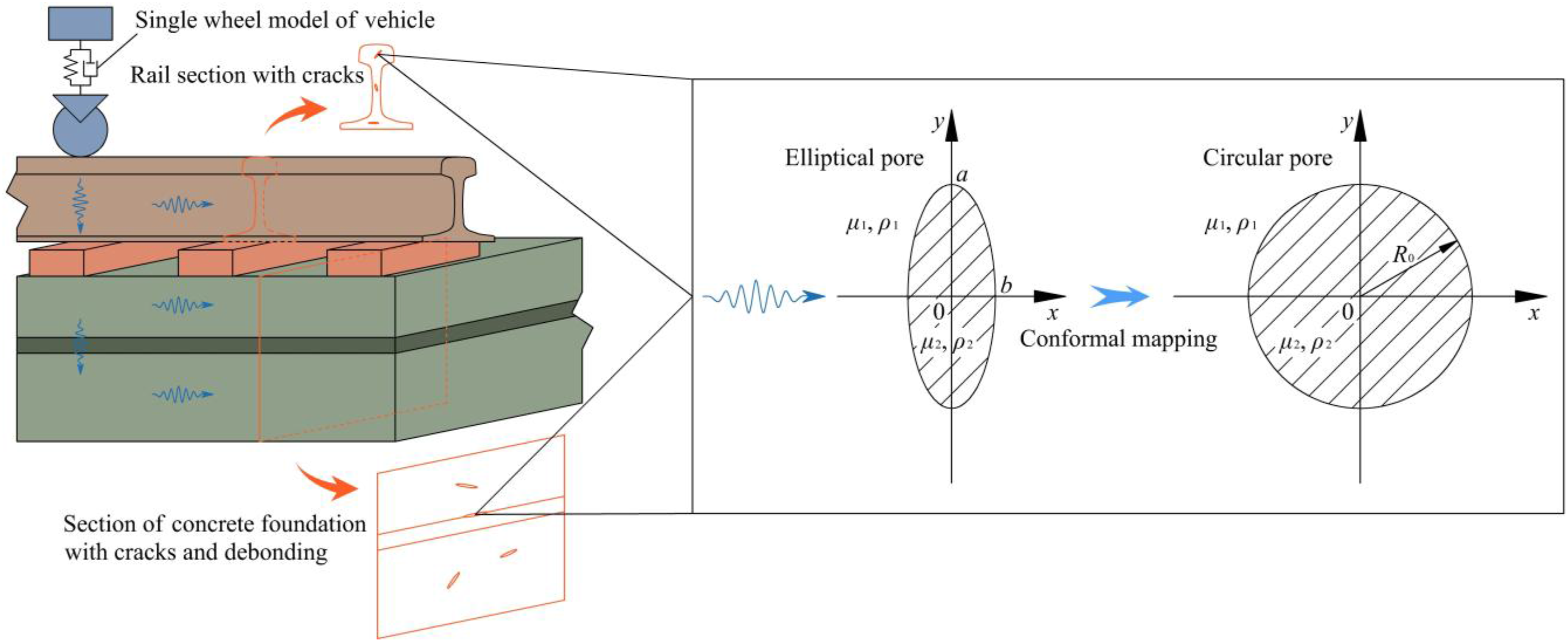
3. SH wave scattering around the pore
To explain the propagation characteristics of SH wave around cracks or debonds in structural components, such defects are initially modeled as circular pores to develop an analytical method for wave scattering at the pores. By adjusting the radius of the circular pore in a direction perpendicular to wave propagation, the pore geometry is transformed into an elliptical shape to more accurately approximate actual structural component defects. The elliptical boundary is transformed using conformal mapping to correspond to the circular pore, and the influence of the elliptical pore on wave propagation is evaluated based on the wave scattering algorithm around circular pores.
3.1. SH wave scattering by the circular pore
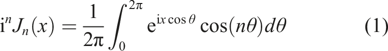
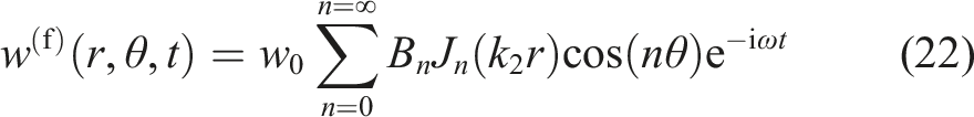
Consider the pore plane as the wave propagation plane, with the pore center coinciding with the origin of the Cartesian coordinate system, as shown in Figure 1, where the incident wave propagates along the x direction. The particle displacement caused by the SH wave is perpendicular to this propagation plane and varies based on the coordinate (x, y). Under resonant conditions, the displacement can be expressed as u = 0, v = 0, w(x, y, t) = w(x, y)e-iωt. If the particle displacement is converted to the cylindrical coordinate system, it can be expressed as w(r, θ, t) = w0ei(krcosθ-ωt), where w0 is the wave amplitude, k = ω/cs is the number of the incident wave, ω is the angular frequency, cs=(μ/ρ)1/2 is the SH wave velocity, μ is the lame constant of the medium, ρ is the medium density, and t is the wave propagation time. The integral of the Bessel function is expressed as
It can be seen from the above formula that
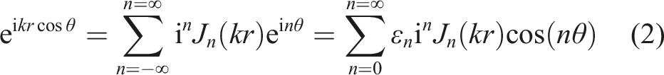
Therefore, the displacement function of the incident wave in the cylindrical coordinate system can be expressed as

The governing equation of the elastic dynamics of the wave propagation medium is defined as
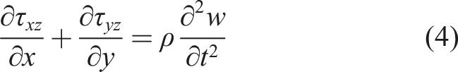
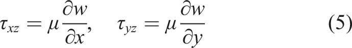
Substituting equation (5) into equation (4) and eliminating the time factor, the Helmholtz equation of steady-state incidence of SH wave is obtained as

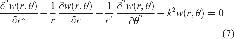
Converting the coordinate system of equation (6), the cylindrical coordinate expression of Helmholtz equation for steady-state incidence of SH wave is obtained as
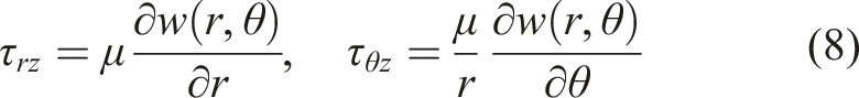
The radial stress τ
rz
and the circumferential stress τ
θz
of the wave propagation plane corresponding to the above formula are
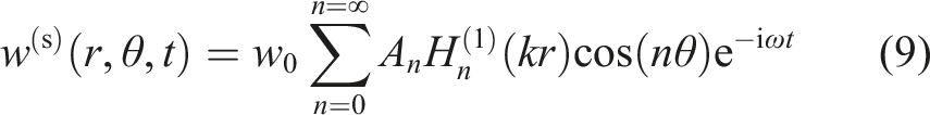
By employing the wave function expansion method to express the incident wave displacement as w(r, θ) = R(r)Θ(r) and substituting it into equation (7), the resultant ordinary differential equation is solved. Retaining only the Bessel function H
n
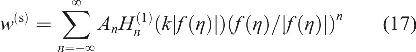
(1) (kr), which describes the divergent wave, the displacement function of the scattered wave is obtained by combining the resonance time factor e-iωt as
Substituting equations (3) and (9) into equation (8), the stress distributions of the incident wave and scattered wave are obtained as
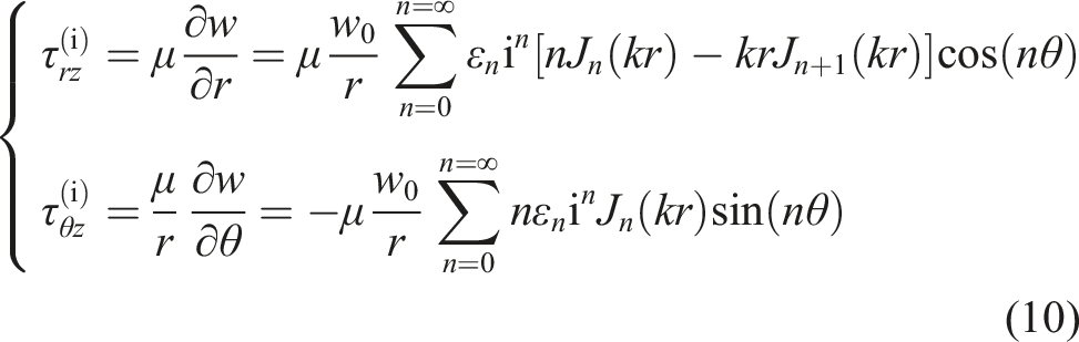
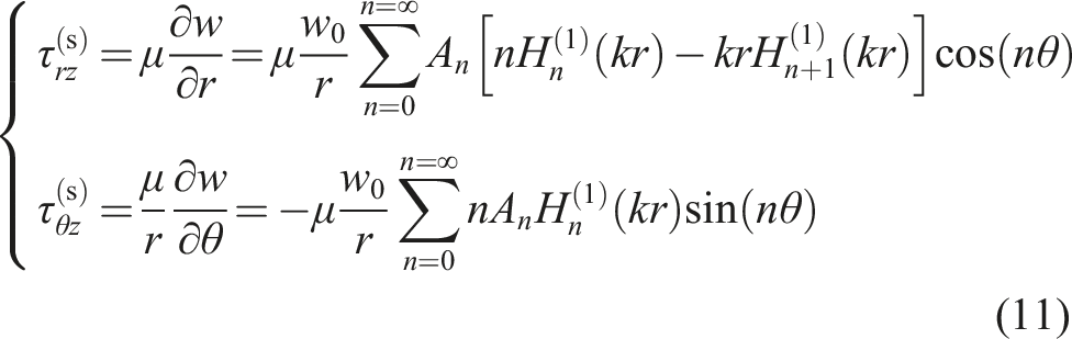

Substituting equations (10) and (11) into equation (12), the coefficient A n and the wave propagation response can be obtained.
3.2. SH wave scattering by the elliptical pore
The elliptical pore is projected onto the circular pore plane through conformal mapping as shown in Figure 1. By introducing the complex plane (z, z*), where the complex variables are defined as z = x+iy, z* = x-iy, if the mapping plane is (η, η*), then the mapping relationship is expressed as

The wave incidence equation (6) in the mapping plane can be expressed as
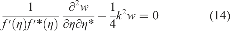
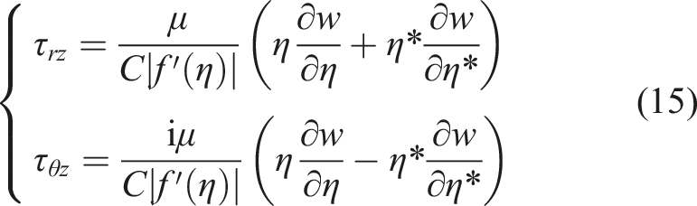
The corresponding stresses are

Equation (14) is also solved by the wave function expansion method, and the Bessel function H
n
(1) (x) is retained to obtain the displacement function of the scattered wave in the complex plane as
By substituting equations (16) and (17) into equation (15), the stress equations for both SH wave incidence and scattering conditions are solved, with the complete solutions omitted for brevity. The obtained τ rz (i) and τ rz (s) are then substituted into the boundary condition equation (12), and the equivalent relationship between the elliptical pore boundary and the circular pore boundary is established by mapping η = Ceiθ, thereby achieving the solution of the wave propagation field.
3.3. Response indexes
3.3.1. Scattering energy
Scattering energy is utilized to represent the intensity and distribution characteristics of scattered waves generated by wave propagation around structural defects. The energy flow rate of area A with unit normal vector

Considering the propagation properties of SH wave, the real parts Re[τ
rz
(s)] = [τ
rz
(s)+τ
rz
(s)*]/2 and Re[w(s)] = [w(s)+w(s)*]/2 of τ
rz
(s) and w(s) are substituted into equation (18), where τ
rz
(s)* and w(s)* are conjugate complex numbers of τ
rz
(s) and w(s), respectively. The steady-state periodic wave exhibits the characteristics that
The time-averaged energy flux per unit area can be obtained as
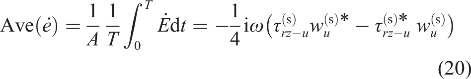
Substituting the expressions of displacement and stress caused by scattered wave around the pore into equation (20), the spatial distribution of scattering energy around the defect is determined.
3.3.2. Dynamic stress concentration
The scattering effect of wave propagation at structural defects leads to varying degrees of dynamic stress concentration around these defects. The total circumferential stress field is obtained as τ
θz
= τ
θz
(i)+τ
θz
(s), as derived from Equations (10) and (11), and the maximum incident stress of SH wave is τ0 = μkw0, thus the dynamic stress concentration factor (DSCF) K can be obtained as

3.4. Model verification
To validate the reliability of the proposed model, the elliptical pore model is degraded to a circular pore model by setting the major and minor semi-axes of the ellipse equal, that is, a = b, and the scattering response around the pore caused by SH wave is calculated and compared with results in the literature (Mow and Pao, 1971). Dimensionless variables are used as input parameters to highlight the response characteristics around the defect due to wave propagation. Specifically, the SH-wave length is set relative to the radius a of the circular pore, with ka = 1.0 as the basic scheme, while additional schemes of ka = 0.1 and 2.0 are also calculated and compared at the same time. The variation of DSCF around the pore is shown in Figure 2. Comparison of results at different incident wavelengths. Solid lines represent the results of this paper, and discrete points denote the results of the literature (Mow and Pao, 1971).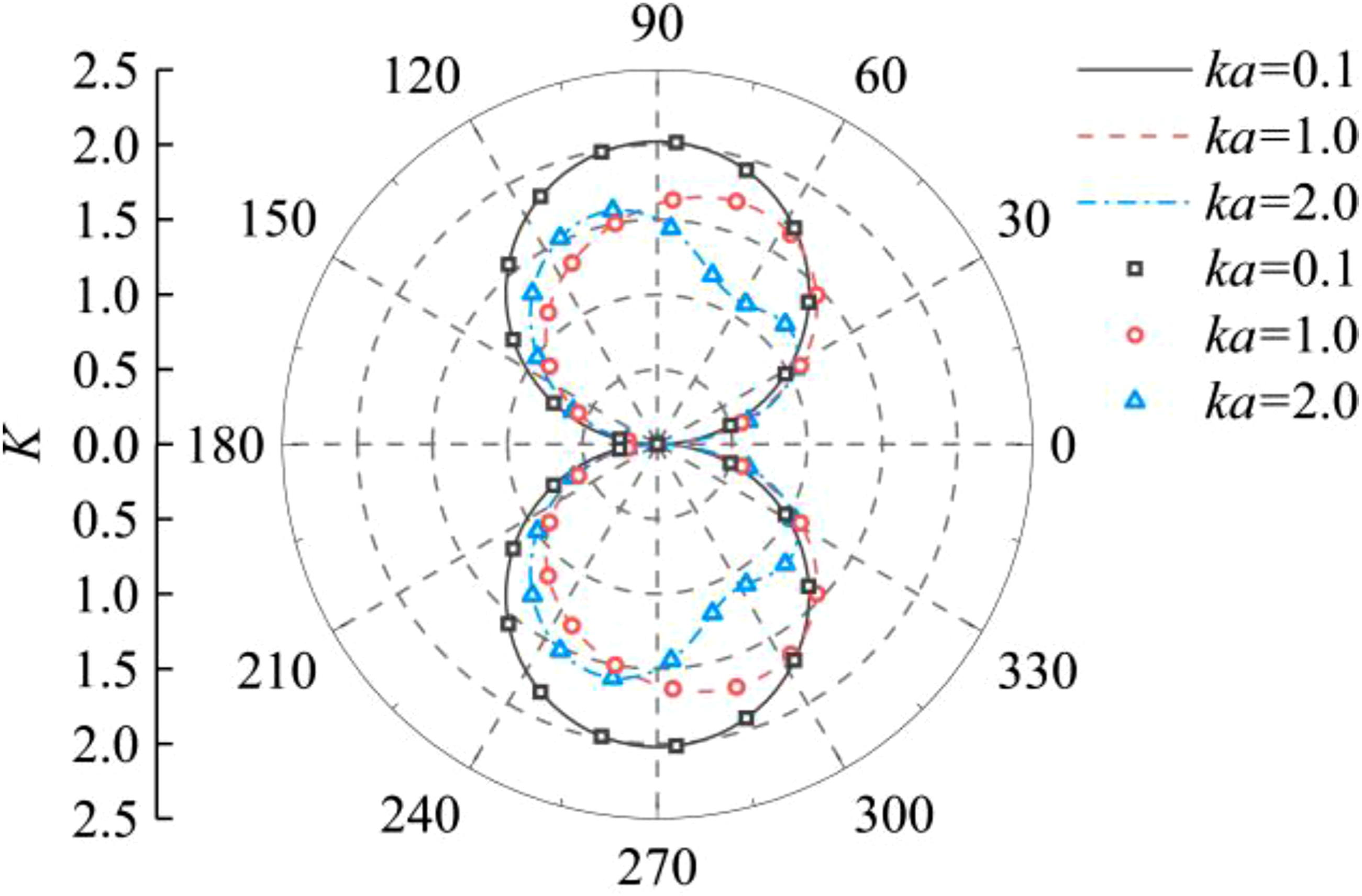
As seen in Figure 2, when SH wave is incident horizontally, the DSCF presents a symmetric distribution relative to the incident wave direction. When ka = 0.1, the wave number is small, and the DSCF remains nearly unchanged both at the front and back of the pore. With increasing wave number, the maximum stress location appears to shift, and oscillations around the pore gradually intensify due to the increased wave number per unit length. When ka = 2.0, DSCF exhibits distinct convex (front of the pore) and concave (back of the pore) profiles. The computational results are in good agreement with those in the literature (Mow and Pao, 1971), which validates the proposed model.
3.5. Wave scattering response
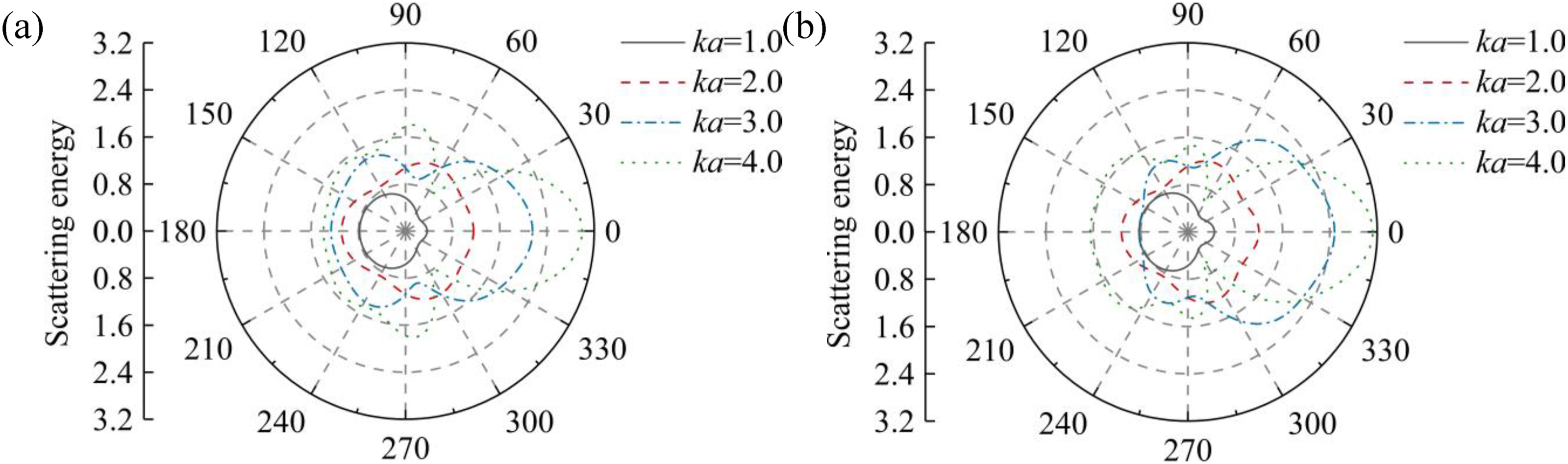
The propagation of elastic waves constitutes a process of energy transfer. When incident waves encounter defects like pores in an elastic medium, the incident energy undergoes diffusive propagation in multiple directions due to obstruction. The energy diffusion states vary according to the geometric characteristics of the pores. To study the effect of pore opening size on wave propagation, five elliptical pore geometries with minor-to-major axis ratio b/a = 1.0, 0.8, 0.6, 0.4, 0.2 are simulated. A smaller ratio signifies a reduced degree of crack opening, primarily indicative of fresh pores or those present in high-integrity materials, such as rails. In contrast, pores with larger openings likely represent defects that have developed due to gradual detachment in concrete subjected to cyclic dynamic action. The wave numbers of the incident wave are considered as relative values: ka = 1.0, 2.0, 3.0, and 4.0. Larger wave numbers correspond to high-frequency excitations from wheel-rail interactions, predominantly occurring within the rail, while low-frequency vibrations from smaller wave numbers are present in both the rail and the underlying foundation. In addition, preliminary calculations indicate that when ka = 0.1, the energy scattering intensity from small wave number is significantly less than in other schemes, and is thus not listed here. Since the energy diffusion around elliptical pores with different geometries reveals a consist pattern, only the middle and minimum axial ratios of the ellipse are considered here, that is, b/a = 0.6 and 0.2, and the distribution of the dimensionless wave scattering energy is calculated and compared with that of the circular pore, as shown in Figures 3 and 4. Wave scattering energy distribution around the circular pore: b/a = 1.0. Wave scattering energy distribution around the elliptical pores: (a) b/a = 0.6; (b) b/a = 0.2.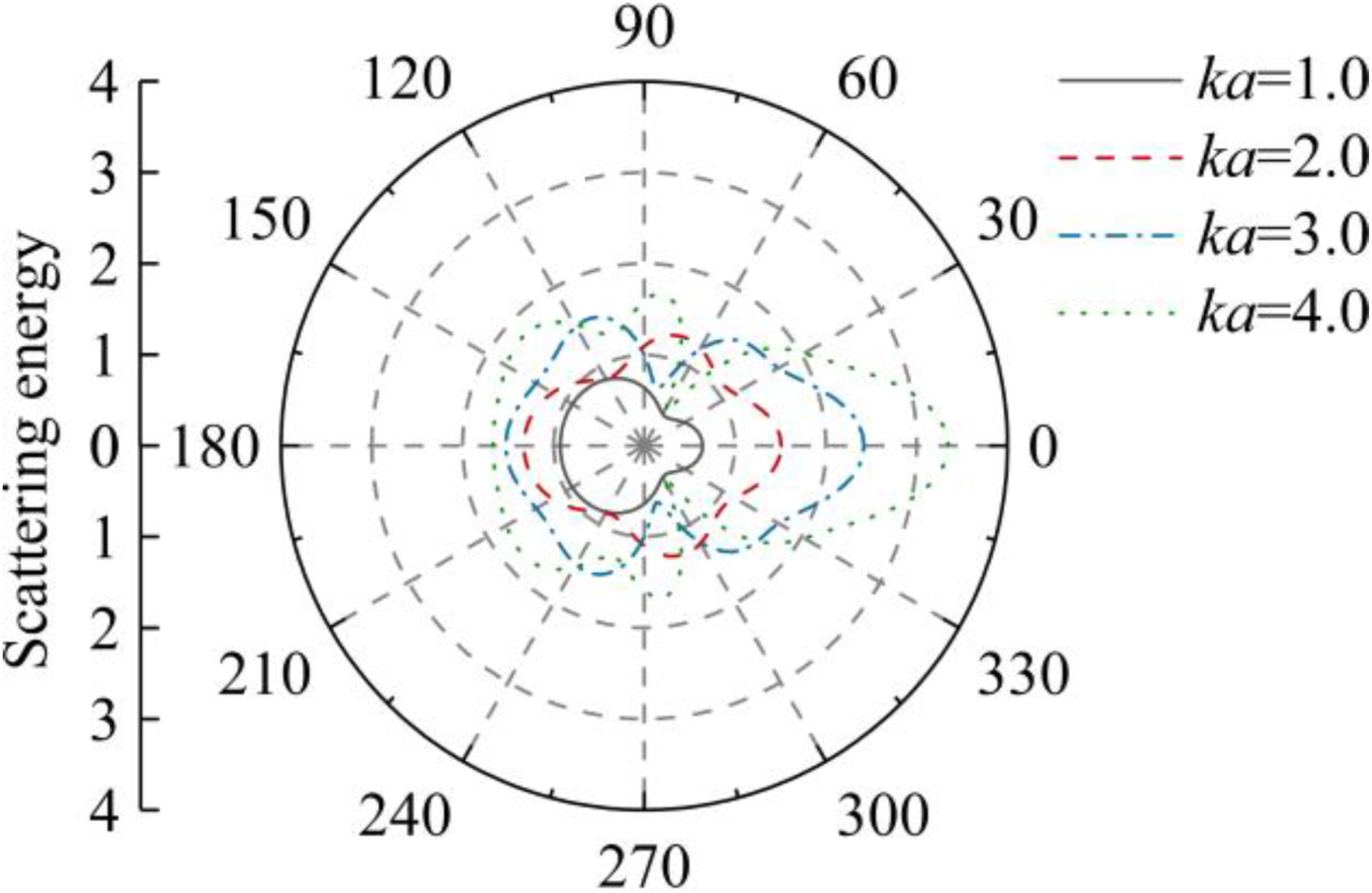
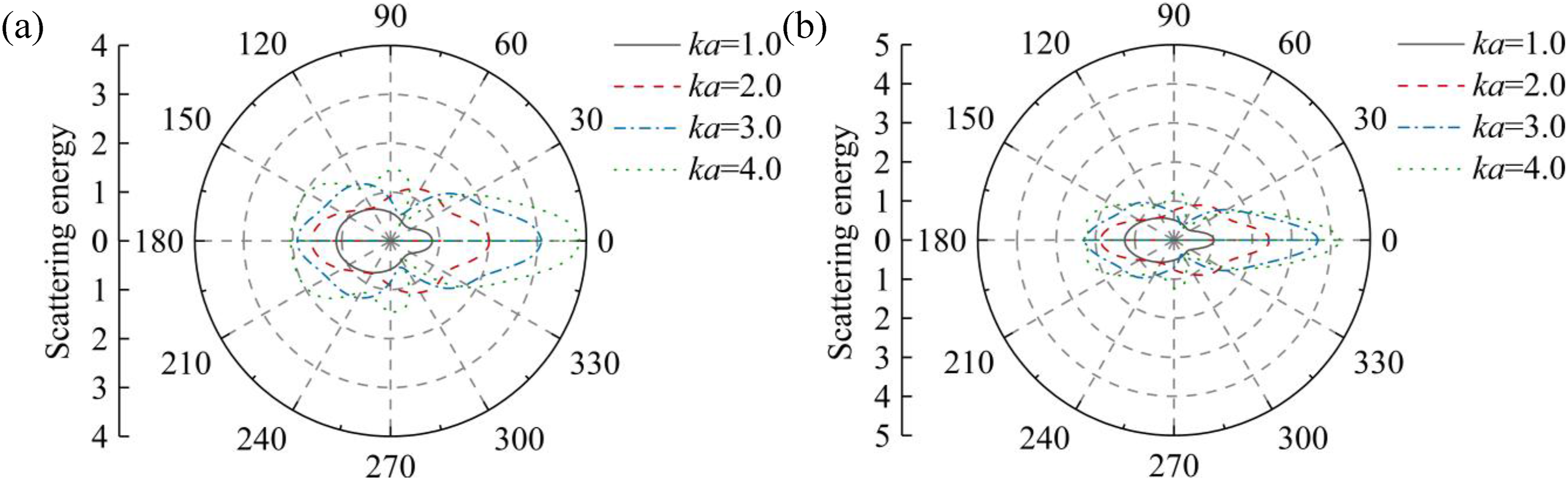
As shown in Figures 3 and 4, the wave scattering energy around the pore increases with the growth of the wave number. The maximum energy gradually concentrates in the 0° direction (behind the pore), while the magnitude in the 180° direction (at the front of the pore) also rises significantly. This phenomenon occurs because an increase in wave number per unit length corresponds to a decrease in wavelength, thereby weakening the ability of wave to traverse the pore along the propagation direction, indicating stronger obstruction effects of the pore and more intense oscillation of energy distribution. The scattering energy distribution in all directions around the defect depends on the pore geometry. The smaller the axial ratio of the elliptical pore, the more concentrated the scattered energy is on the central axis of wave propagation, as shown in Figure 4. Consequently, the energy amplitude along this axis becomes notably higher compared to that of the circular pore.
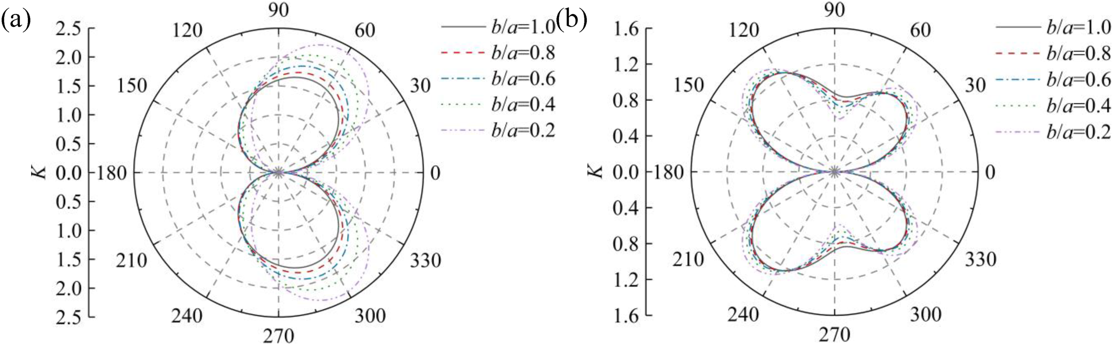
The scattering of wave propagation energy induces an uneven stress distribution around the pore. The variation of DSCF distribution with wave number under different axial ratios of the pore follows a trend consistent with that in Figure 2, which will not be elaborated here. However, when analyzed with Figure 4, it can be found that the dynamic stress is mainly concentrated at the area adjacent to both ends of the major axis of the elliptical pore where the wave transmits more readily. As further observed in Figure 2, with the increase of wave number, the maximum of DSCF shifts from 90° to approximately 60° and 120° (with symmetric results on the lower side). Therefore, the variation laws of DSCF around the pore at angles of 60° and 120° with varying b/a are chosen for comparative analysis against those at 90°, as shown in Figures 5 and 6. DSCF around the pore: θ = 90°. DSCF around the pore: (a) θ = 60°; (b) θ = 120°.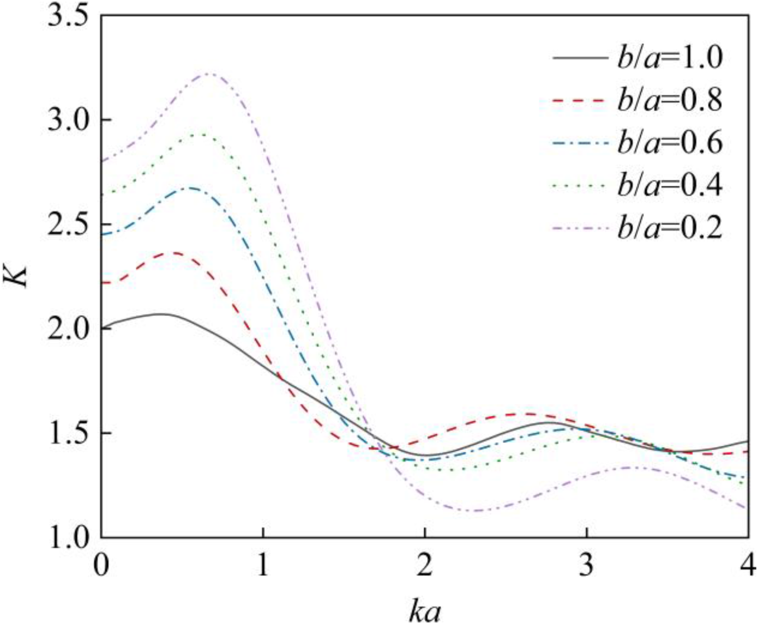
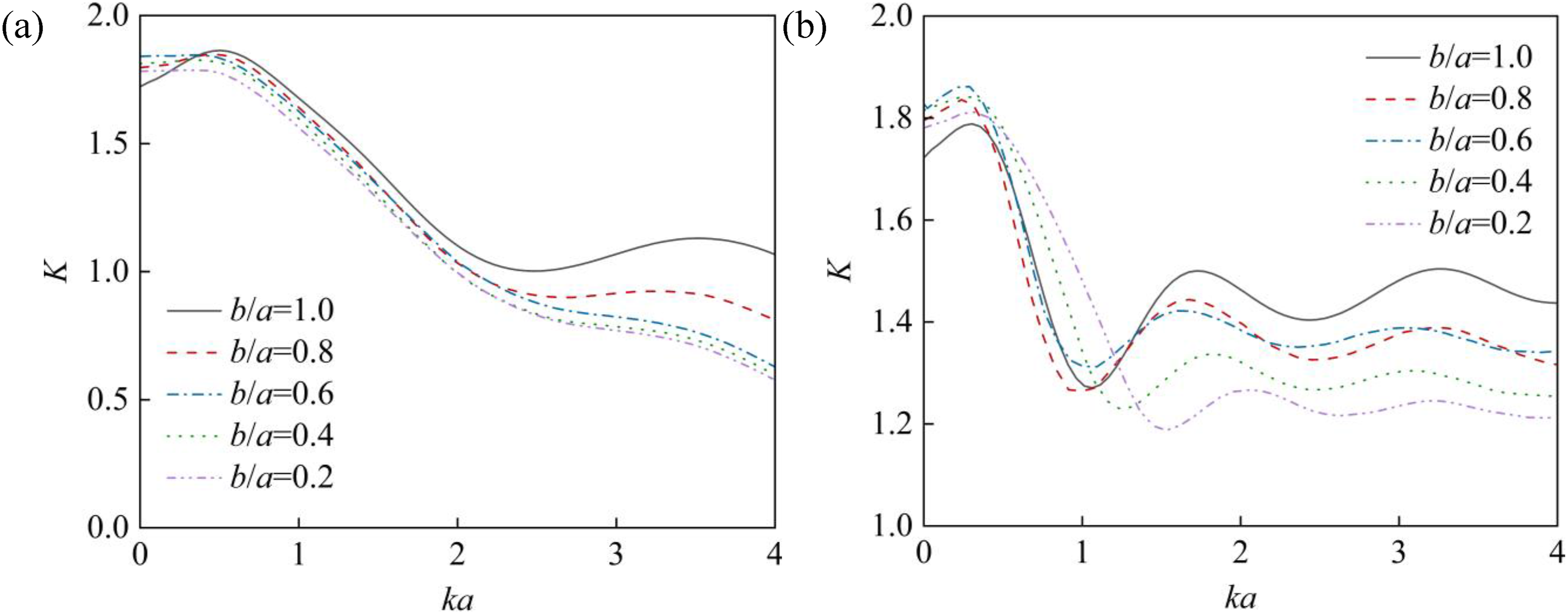
In Figures 5 and 6, DSCF in all directions shows a reciprocating downward trend with increasing wave number. The DSCF at 90° and 60° reaches its peak around ka = 0.5, followed by a rapid decline before ka = 2.0, whereas the DSCF reduction at 120° occurs within a narrower wave number range (ka = 0.2-1.0). This indicates that lower wave numbers lead to more pronounced dynamic stress concentration near the defect, delineating a sensitive wave number region for dynamic stress variations. As the two ends of the elliptical pore become sharper with a decrease of b/a, they are theoretically more susceptible to stress concentration. This is confirmed by the rapid increase of DSCF with the decrease of b/a at 90° within the sensitive wave-number region in Figure 5. However, at 60° and 120° in Figure 6, away from the ellipse tip, DSCF does not show great difference with variations in b/a, even within the sensitive wave-number region where dynamic stress changes. Beyond the sensitive wave-number region, DSCF weakens with decreasing b/a, indicating that the dynamic stress concentration around the defect is alleviated at smaller wavelengths.
4. Influence of inclusions in a pore
When the defect is filled with inclusions, the wave propagation mode near the pore will be adjusted. On the basis of the aforementioned wave scattering around the pore, a near-field wave propagation model of the pore containing inclusions is established to comparatively analyze the influence of inclusions with different properties on wave scattering.
4.1. Wave propagation model
When the SH wave propagates towards a circular pore containing inclusions, besides the interfacial scattered waves at the pore boundary, a portion of the wave is transmitted into the pore through the inclusions. The scattered and transmitted waves are described using the displacement and stress functions of the wave in the medium as outlined in Section 2. The incident wave is expressed by Equations (3) and (10), with the structural component serving as the propagation medium. The lame constant and material density are denoted as μ1 and ρ1, respectively, with the corresponding wave number being k1. Scattered waves also exist in the structural medium and can be described by Equations (9) and (11). Transmitted waves pass through the pore interface and into the inclusion. If the wave number corresponding to the lame constant μ2 and material density ρ2 of the inclusion is k2, the standing wave displacement function formed in the inclusion is expressed as
Substituting Equation (22) into (8), the transmitted wave stress functions τ
rz
(f) and τ
θz
(f) are derived. Due to the inclusion, the radial stress and displacement around the pore are coordinated and continuous, and the boundary condition is
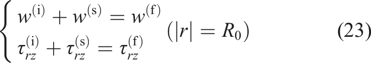
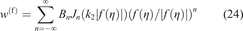
For the near-field wave propagation of an elliptical pore containing inclusions, the conformal mapping relationship shown in equation (13) is employed to project the elliptical pore onto the circular pore plane. The displacement functions of incident and scattered waves are expressed as Equations (16) and (17), respectively, with the original structural component serving as the propagation medium. The displacement function of the wave transmitted through the inclusion is expressed as
The wave stress distribution is obtained by substituting Equation (24) into (15). The boundary conditions of this model remain as defined in equation (23).
4.2. Scattering energy distribution
An analysis of the scattering characteristics of the wave energy at the pore without inclusions reveals that the ellipse axial ratio only affects the amplitude, not the distribution of scattering energy. Therefore, the circular pore (b/a = 1.0) containing inclusions is taken for analysis to compare the influence of different types of inclusions on the wave energy scattering around the pore, as shown in Figures 7 and 8. Given the substantial differences in material properties between steel and concrete within track structures, along with diverse inclusion sources, both materials may contain impurities of varying hardness. By adjusting the ratio μ1/μ2, inclusions with varying hardness relative to the original medium can be uniformly characterized. Among these, inclusions softer than the track material exhibit a broader range of sources, resulting in a wider range of corresponding μ1/μ2 values. Wave scattering energy distribution around circular pore with hard inclusion: μ1/μ2 = 0.2. Wave scattering energy distribution around circular pore with soft inclusions: (a) μ1/μ2 = 5.0; (b) μ1/μ2 = 15.0.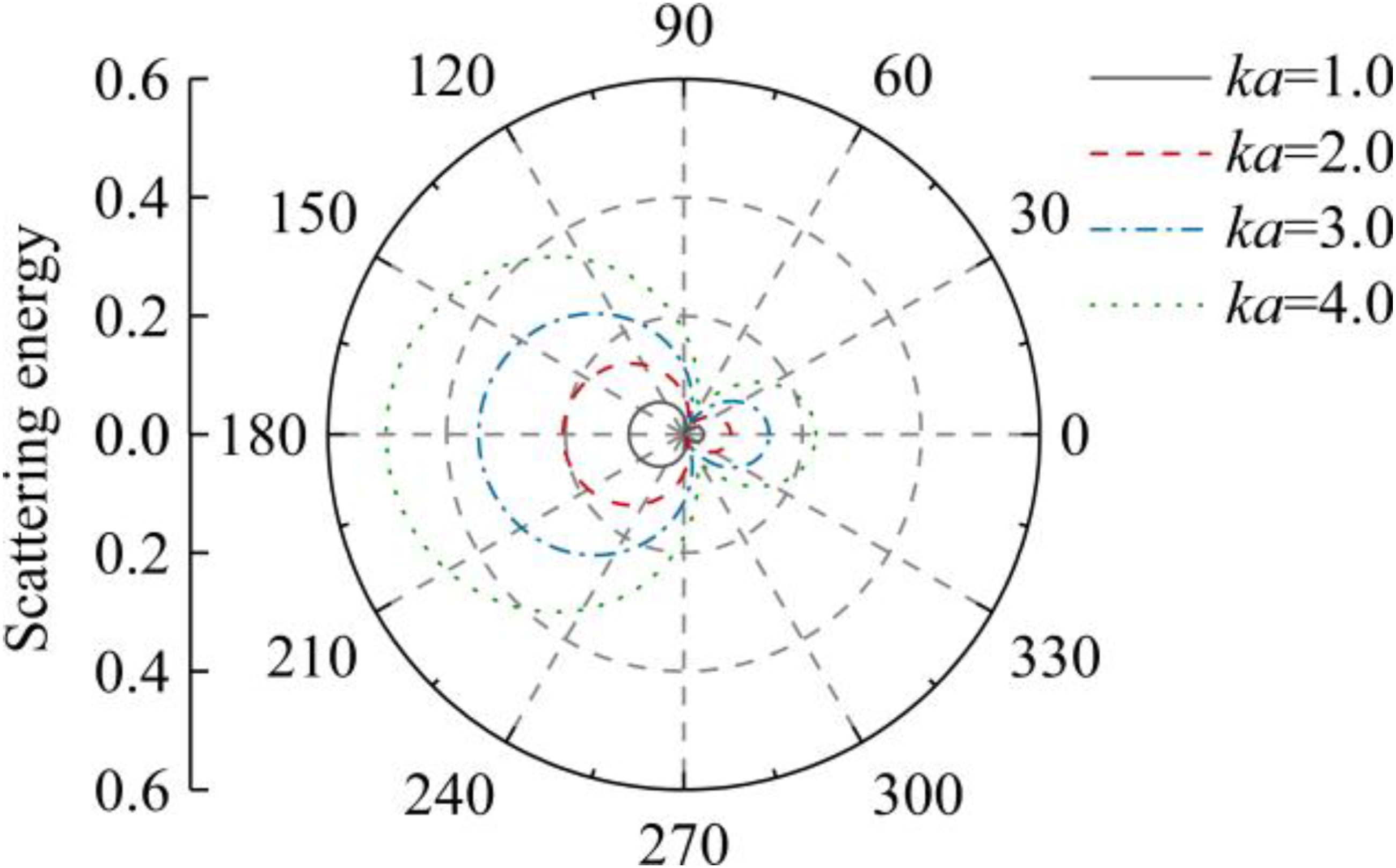
The wave scattering energy distribution around the pore containing inclusions with the varying of wave numbers is similar to that of the pore without inclusions, as shown in Figure 3. Specifically, larger wave numbers result in more intense energy scattering, with the most significant scattering occurring at 0° and 180° along the wave propagation axis. The hard inclusion depicted in Figure 7 facilitates wave penetration through the pore. Although the scattering at the front of the pore is significantly stronger than behind it, the energy amplitude is much lower than that in Figure 8, which contain soft inclusions. When the pore contains soft or softer inclusions, the scattering energy around it oscillates with increasing wave number. The maximum shifts gradually from 180° to 0°, and the distribution pattern becomes more similar to that of the pore without inclusions. In summary, although inclusions do not change the relationship between wave number and wave scattering intensity, hard inclusions affect the scattering energy distribution mode, amplitude and peak position.
4.3. Dynamic stress concentration
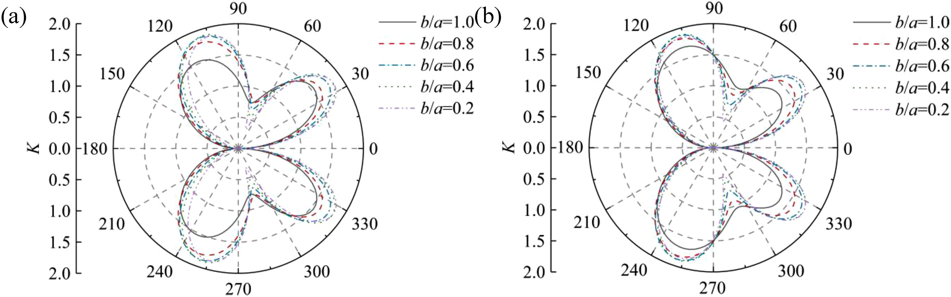
Building upon the three different types of inclusions analyzed above, and considering variations in the axial ratio b/a of the elliptical pore, the DSCF distribution around the pore at ka = 1.0 is further analyzed, as shown in Figures 9 and 10. DSCF around the pore with hard inclusion at ka = 1.0: μ1/μ2 = 0.2. DSCF around the pore with soft inclusions at ka = 1.0: (a) μ1/μ2 = 5.0; (b) μ1/μ2 = 15.0.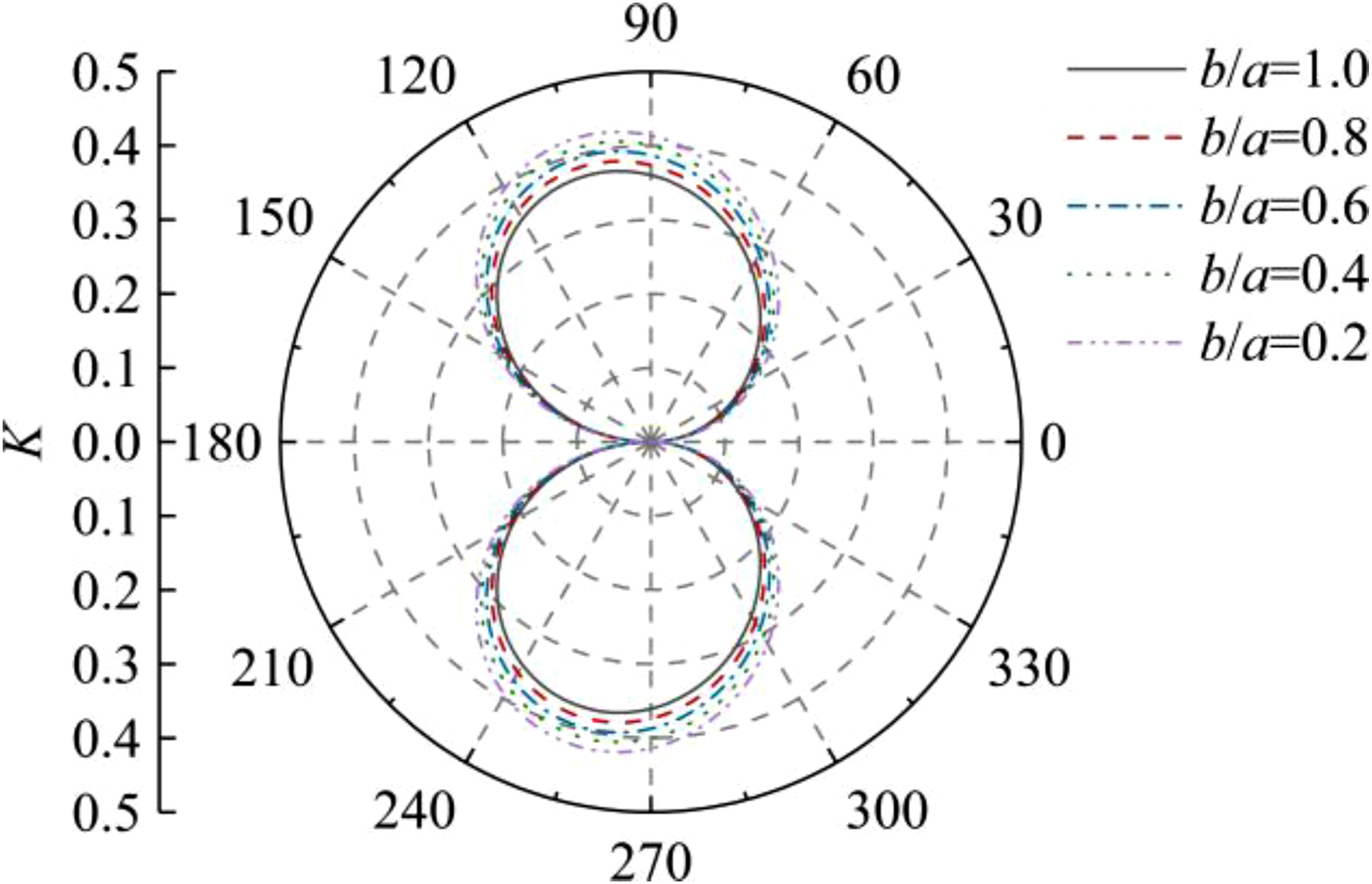
In the wave propagation, different degrees of scattering occur at the front and back of the pore, with some scattered waves superimposing at both tips of the ellipse’s major axis, forming the DSCF symmetrically distributed along the wave incidence axis around the pore. The presence of inclusions causes the maximum DSCF to deviate from the ellipse’s major axis. Softer inclusions intensify wave scattering, and the DSCF distribution demonstrates oscillation characteristics, leading to stress peaks at the front and back of the pore. A reduction in the axial ratio sharpens the ellipse geometry, resulting in intensified stress concentration at major axis termini, and the DSCF increase with the decrease of b/a for each inclusion. However, the DSCF with an oscillating distribution decreases significantly at the concave points as b/a decreases, due to the normal direction of the wave reflection surface of the flat elliptical pore being closer to the wave incidence axis, causing the scattered waves to gradually gather at the front and back of the pore.
For comparison, the DSCF distribution around the elliptical pore at ka = 2.0 is shown in Figures 11 and 12. DSCF around the pore with hard inclusion at ka = 2.0: μ1/μ2 = 0.2. DSCF around the pore with soft inclusions at ka = 2.0: (a) μ1/μ2 = 5.0; (b) μ1/μ2 = 15.0.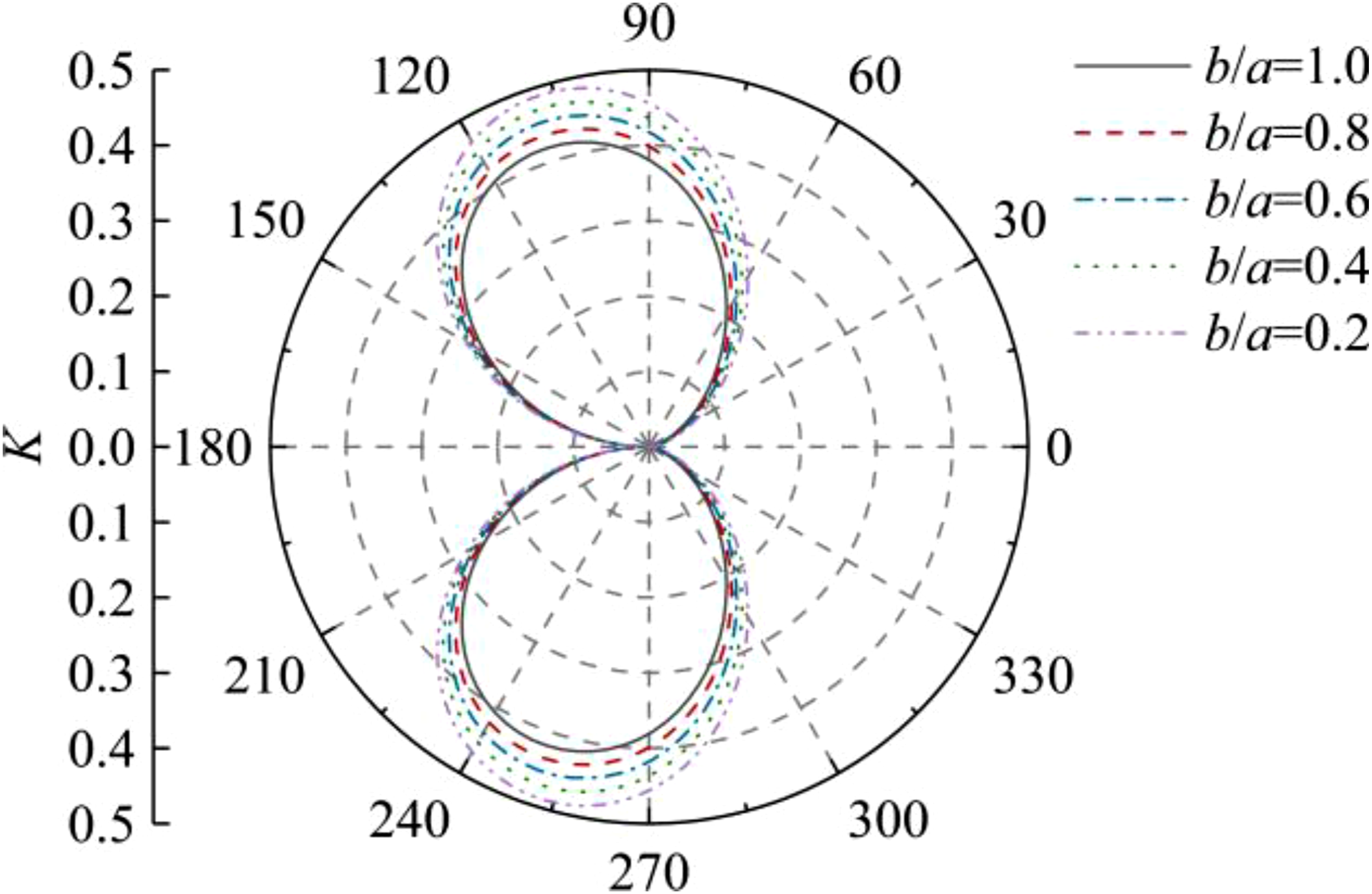
The comparison reveals that the distribution of DSCF around the elliptical pore in Figures 11 and 12 is similar to that in Figures 9 and 10. However, the increased wave number causes the DSCF to exhibit oscillatory behavior around the pore containing soft inclusions. Moreover, at ka = 2.0, wave scattering tends to concentrate at the back of the pore as the inclusion softens, causing the overall DSCF distribution to rotate and shift towards the back of the pore.
In conclusion, both inclusion hardness and incident wave number affect the distribution pattern and amplitude localization of wave scattering, thereby altering the curve style and peak direction of DSCF around the pore. Furthermore, the peak of DSCF shows a unidirectional correlation with the axial ratio of the ellipse.
5. Discussion
This study focuses on the scattering field distribution mode generated by SH-wave vertical incidence in the medium containing an elliptical pore. It should be noted that the waves reflected from the boundary of track components may superimpose with the wave field around the defect, potentially interfering with the original assessment of wave scattering characteristics in the target area. Therefore, this study specifically focuses on wave propagation in the medium containing internal microcracks. In other words, when the pore, relative to the wavelength scale, is distant from the component boundary, the dynamic response can be analyzed by observing the initial distribution mode of the wave field triggered by wave incidence. This approach enables the evaluation of the dynamic stability of the internal defect region within the track structure using wave field signals obtained in wave calculation or detection.
For rails, wheel-rail excitation generates a broadband frequency, meaning that the dynamic stress concentration around the defect depends on the incident wave composition, necessitating an expanded observation range of wave numbers. After transmission through fasteners to track foundation components, middle and high-frequency waves are largely filtered out, and low frequency waves dominate the dynamic stress concentration around defects.
Inclusions modulate the distribution of dynamic stress concentration around the pore. Inclusions with properties similar to the structural material enhance wave transmission, greatly reducing the amplitude of dynamic stress concentration. However, excessively soft inclusions drastically change the position and magnitude of dynamic stress concentration peaks around defects. Therefore, the form and range of wave scattering should be analyzed based on the material properties of inclusions in the pores of track components.
This paper provides a theoretical foundation for future engineering applications, concentrating on research topics characterized by strong specificity. Given the research process is oriented toward engineering structures, the established model is applicable to continuum homogeneous media exhibiting significant wave propagation capabilities. This facilitates the effective differentiation of scattering effects induced by local pores within the medium. Subsequent studies will address phenomena such as near-boundary pores and the simultaneous presence of multiple cavities, which may occur in actual structures. On the basis of the core problem and theoretical algorithms discussed, future research on wave propagation in the defective areas of track components should fully consider the wave characteristics in rails and foundation components caused by wheel-rail interaction, to reflect the further expansion of structural damage under train operation. Furthermore, when utilized as a theoretical reference for damage detection, the frequency of the incident wave should be adjusted according to the anticipated defect size. A comparative analysis of excitation wave scattering across different frequency bands should be conducted, and the wave with the most significant effect should be identified as the basis for damage evaluation.
6. Conclusions
Pores in track components change the distribution pattern of far-field wave propagation to these defects. The core issue of this engineering phenomenon was raised in this study. The defective structure was simulated as a medium with the elliptical pore, and the typical SH wave was selected as the incident waveform to explore the influence of pore geometry, inclusions, and incident wave properties on wave propagation scattering. The application of simulation and detection signals in track structure damage evaluation based on wave method was proposed. The conclusions are drawn as follows. • The wave scattering energy around a pore in the medium, caused by the vertical incidence of SH waves, intensifies with increasing wave number, leading to the oscillatory distribution characteristics. The maximum scattering energy at the front and back of the pore is concentrated along the wave incidence axis. The presence of inclusions could mitigate the energy scattering, which was particularly pronounced for hard inclusions. • The scattered energy around the flat pore is more concentrated towards the wave incidence axis, and the dynamic stress concentration becomes particularly pronounced at the major axis termini of the pore. As the wave number multiplies relative to the pore size and the wavelength decreases rapidly, the dynamic stress concentration is significantly reduced. • The physical properties of inclusions affect the distribution pattern of dynamic stress concentration induced by wave propagation. Soft inclusions promote the oscillatory DSCF on the pore surface, generating a multi-peak curve. With the increase of incident wave number, this oscillation characteristic becomes progressively easier to be excited, directly correlating with the oscillation of scattered energy.
Footnotes
Funding
The authors disclosed receipt of the following financial support for the research, authorship, and/or publication of this article: This work was supported by the Natural Science Foundation of Fujian Province (Grant No. 2025J01473 and 2025J01994).
Declaration of conflicting interests
The authors declared no potential conflicts of interest with respect to the research, authorship, and/or publication of this article.